LG Electronics USA N225WUZ Part15 Subpart B-LCD Monitor User Manual BEJN225WUZ
LG Electronics USA Part15 Subpart B-LCD Monitor BEJN225WUZ
Contents
- 1. BEJN225WUZ_User Manual
- 2. BEJN225WUZ_User Manual 2
BEJN225WUZ_User Manual

www.lg.com
OWNER'S MANUAL
NETWORK MONITOR
N195WU
N225WU
Please read the safety information carefully before using the product.
Network Monitor Model
ENGLISH

2
ENG
ENGLISH
Table of Contents
TABLE OF CONTENTS
3 ASSEMBLING AND
PREPARING
3 Unpacking
4 Parts and buttons
7 Lifting and moving the Monitor set
7 Setting Up the Monitor set
7 - Attaching the Stand Base
8 - Detaching the stand base
8 - Adjusting the stand body
9 - Adjusting the angle
9 - Mounting on a table
10 - Using the Kensington locking device
11 - Detaching the stand body
11 - Installing the wall mount plate
12 - Mounting on a wall
13 USING THE MONITOR SET
13 Using Primary Station
13 - D-SUB IN connection - PC
14 Using Standard Stations
14 - USB cable connection - PC
14 - USB cable connection to Daisy Chain
15 - Peripheral device connection
15 - Self Image Adjustment
16 CUSTOMIZING SETTINGS
16 Accessing The Main Menus
17 MENU Settings
17 - Picture
18 - Color
19 - Display
20 - Volume
21 - Others
22 SMART+ Settings
(Only N195WU model)
22 - Auto Bright
23 - Original Ratio
24 AUTO Settings : D-SUB Input
25 TROUBLESHOOTING
27 PRODUCT SPECIFICATION
29 Preset Mode
29 Power Indicator
29
29
30 PROPER POSTURE
30 Proper posture for using the monitor
3
ENG
ENGLISH
ASSEMBLING AND PREPARING
ASSEMBLING AND PREPARING
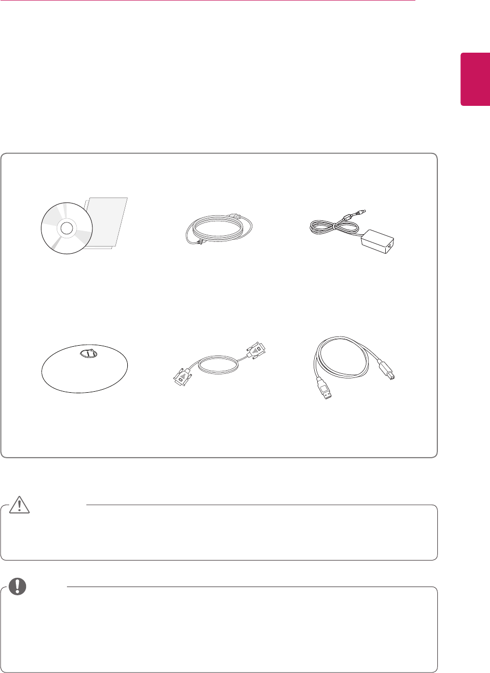
Unpacking
Please check whether all the components are included in the box before using the product. If there are
missing components, contact the retail store where you purchased the product. Note that the product and
components may look different from those shown here.
yOnly use an approved LG power adapter.
yDamage caused by other power adapters is not covered by warranty.
yNote that the components may look different from those shown here.
yWithout prior notice, all information and specifications in this manual are subject to change to improve
the performance of the product.
yTo purchase optional accessories, visit an electronics store or online shopping site or contact the retail
store where you purchased the product.
Power Cord
User Manual/
Software Installation CD/
Card
Stand Base
AC/DC adaptor
CAUTION
NOTE
15-pin D-SUB Signal Cable A-B Type USB Cable
6
ENG
ENGLISH
ASSEMBLING AND PREPARING
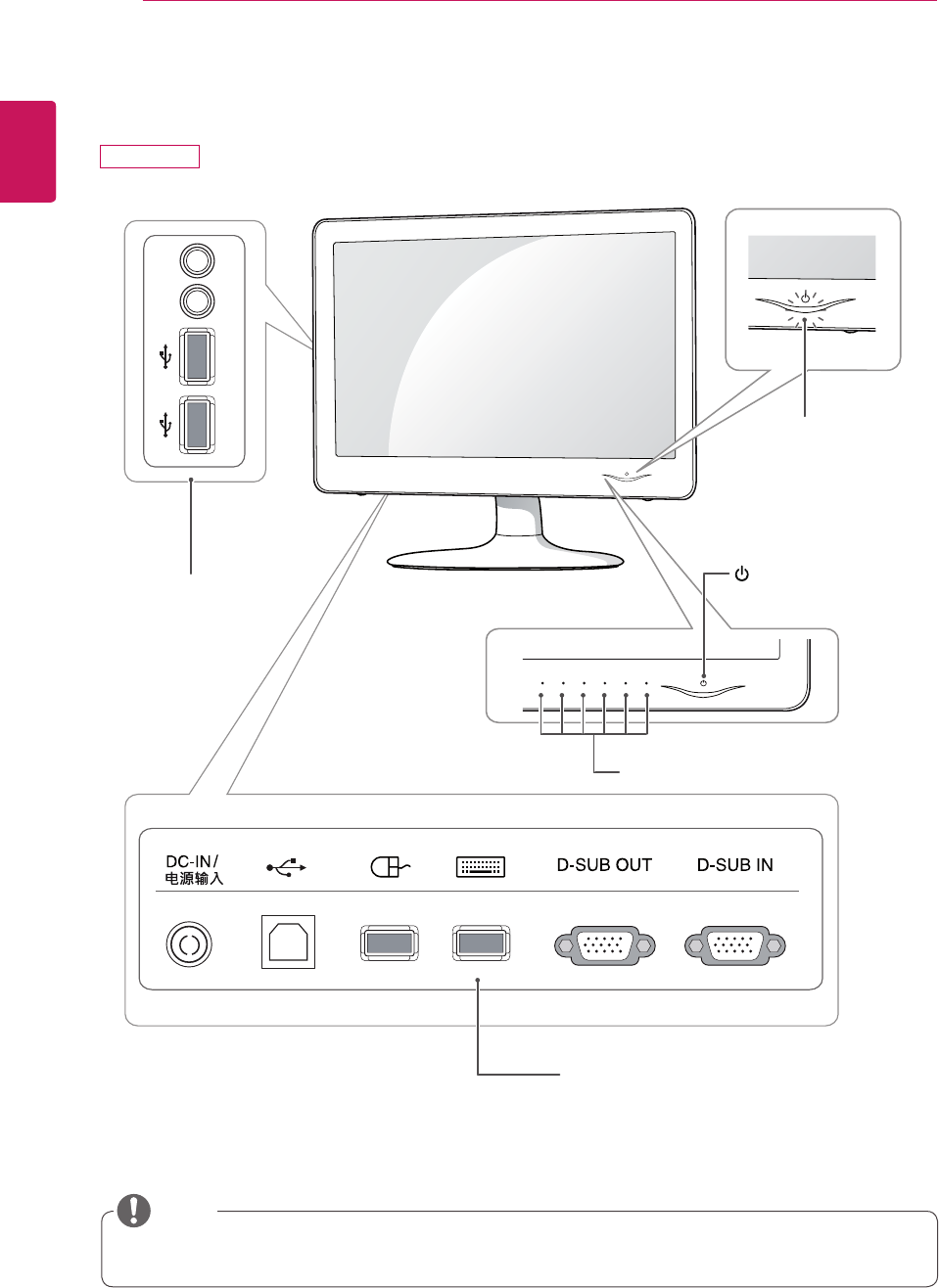
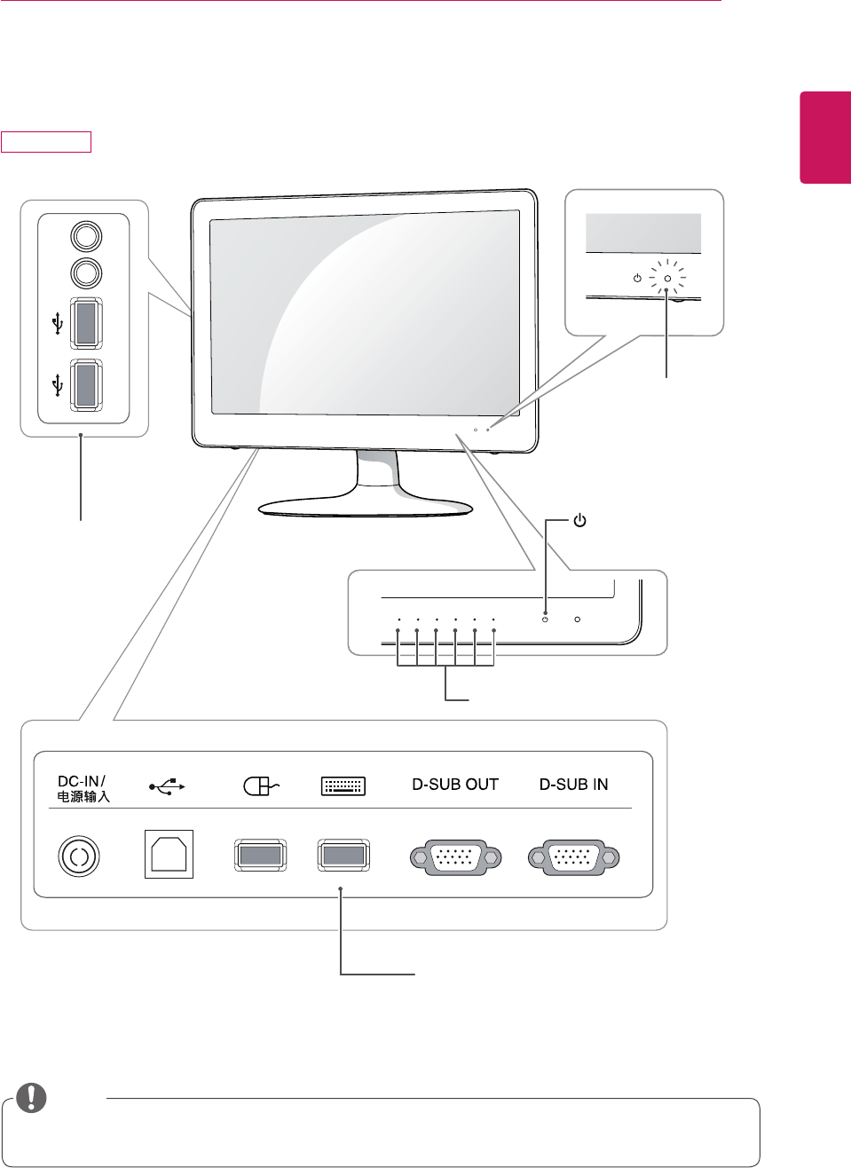
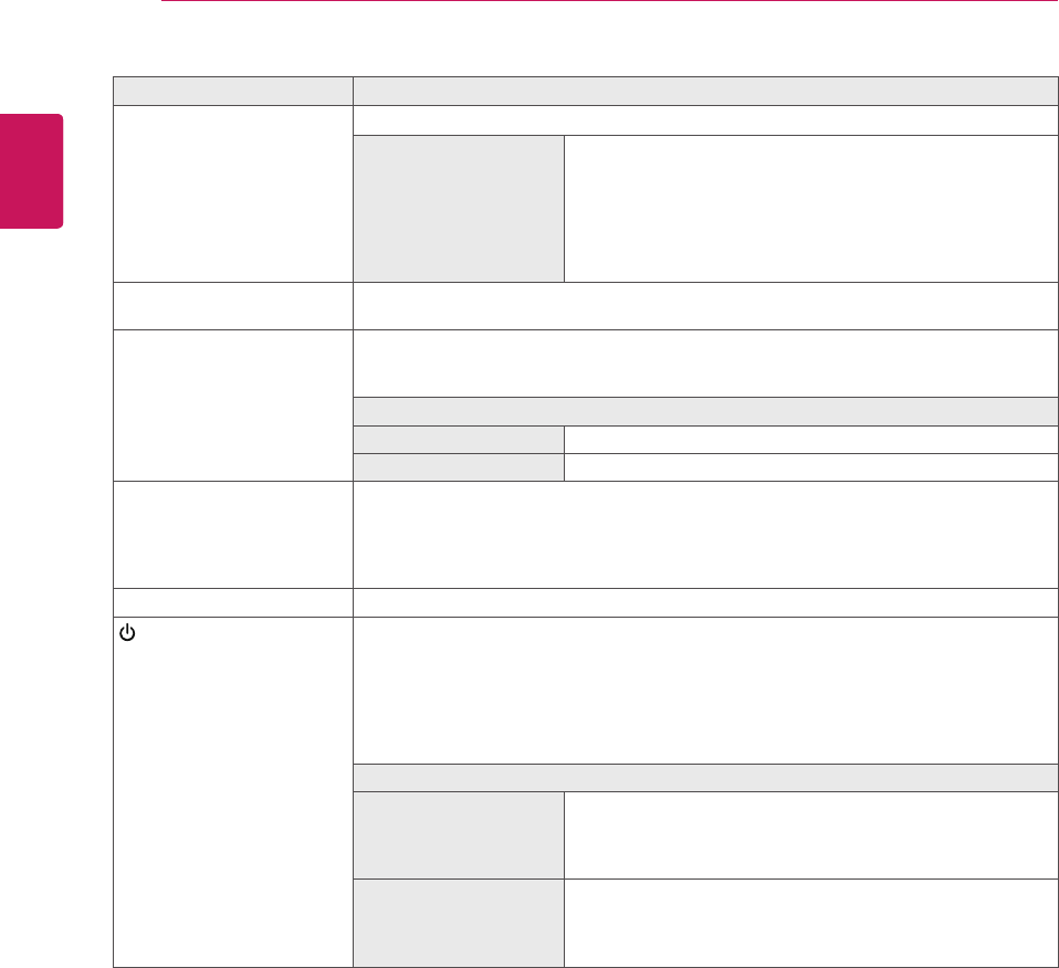
Button Description
MENU Activates the main menu.
OSD Lock/Unlock
Functions
Locks/unlocks the OSD screen.
yTo lock the OSD screen, press and hold the MENU button
for several seconds. The "OSD LOCKED" message will be
displayed and the screen will be locked.
yTo unlock the OSD screen, press and hold the MENU
button again for several seconds. The "OSD UNLOCKED"
message will be displayed and the screen will be unlocked.
SMART+ Use this button to enter AUTO BRIGHT(Only N195WU model), ORIGINAL RATIO
menus.
AUTO To adjust the monitor settings, press the AUTO button on the MONITOR SETUP OSD
menu (only supported for analog signal(D-SUB)).
For optimal screen display, use the following resolution.
Optimal Resolution
N195WU 1366 x 768
N225WU 1920 x 1080
INPUT Allows selection of the input signal.
yIf you connect the monitor to a computer using a D-SUB cable, select either the USB
or D-SUB input signal.
yIf only one computer is connected to the monitor, the input signal is detected automati-
cally. The initial input signal is USB.
EXIT Exits the OSD menu.
(Power Button) D-SUB input
yUse this button to switch the monitor on or off.
USB input
yOn : Press the power button to turn on the power.
yMonitor Off : If you press the power button, the monitor will automatically turn off after
5 seconds.
yUSB Off : Press the power button twice to turn off the USB power.
Power Indicator
N195WU When the monitor is in operating mode, the power indicator
will turn purple (on mode).
When the monitor is in power saving mode, the power indica-
tor will blink purple.
N225WU When the monitor is in operating mode, the power indicator
will turn blue (on mode).
When the monitor is in power saving mode, the power indica-
tor will blink blue.
7
ENG
ENGLISH
ASSEMBLING AND PREPARING
Setting Up the Monitor set
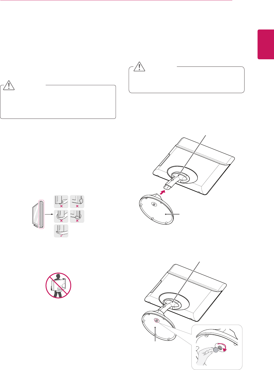
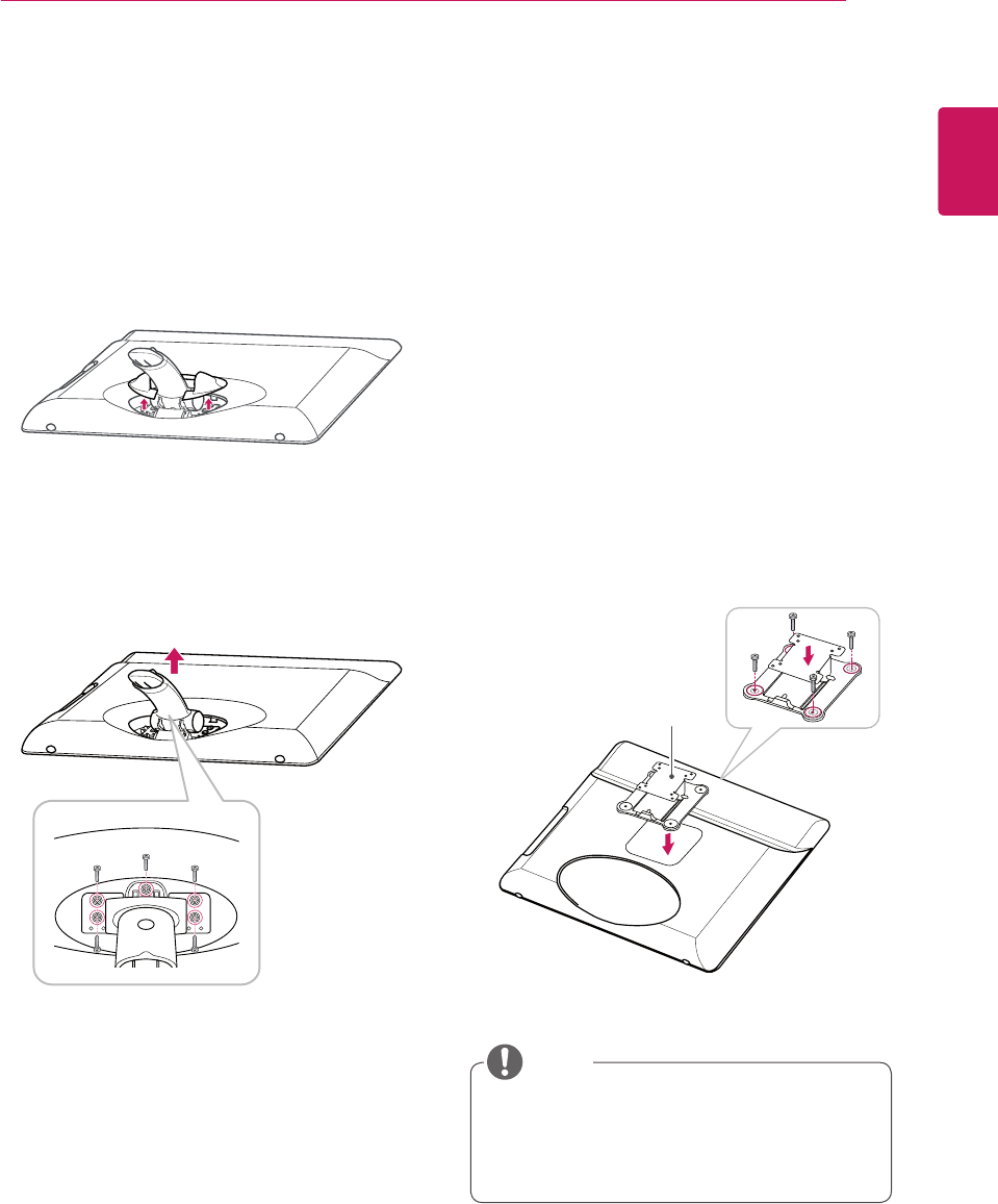
Attaching the Stand Base
1 Place the monitor's screen face down.
yTo protect the screen from scratches, cover
the surface with a soft cloth.
3 Using a coin, turn the screw clockwise to se-
cure the stand base.
2 Check the position (at the front and rear) of
the stand body, then mount the stand base on
the stand body as shown in the figure.
Stand Body
Stand Base
Stand Base
CAUTION
Stand Body
Lifting and moving the
Monitor set
When moving or lifting the Monitor set, read the
following to prevent the Monitor set from being
scratched or damaged and for safe transportation
regardless of its type and size.
yAvoid touching the screen at all times, as this
may result in damage to the screen or some
of the pixels used to create images.
CAUTION
yIt is recommended to move the Monitor set in
the box or packing material that the Monitor
set originally came in.
yBefore moving or lifting the Monitor set,
disconnect the power cord and all cables.
yHold the top and bottom of the Monitor
set frame firmly. Make sure not to hold the
transparent part, speaker, or speaker grill
area.
yWhen holding the Monitor set, the screen
should face away from you to prevent the
screen from scratches.
yWhen transporting the Monitor set, do not
expose the Monitor set to jolts or excessive
vibration.
yWhen transporting the Monitor set, keep the
Monitor set upright, never turn the Monitor
set on its side, or tilt towards the left or right.
8
ENG
ENGLISH
ASSEMBLING AND PREPARING
yThe components appearing in the illustra-
tions may look different from the actual prod-
uct.
yDo not carry the monitor upside-down as this
may cause it to fall off its stand, resulting in
damage or injury.
yTo avoid damaging the screen when lifting
or moving the monitor, only hold the stand or
the plastic cover. This avoids putting unnec-
essary pressure on the screen.
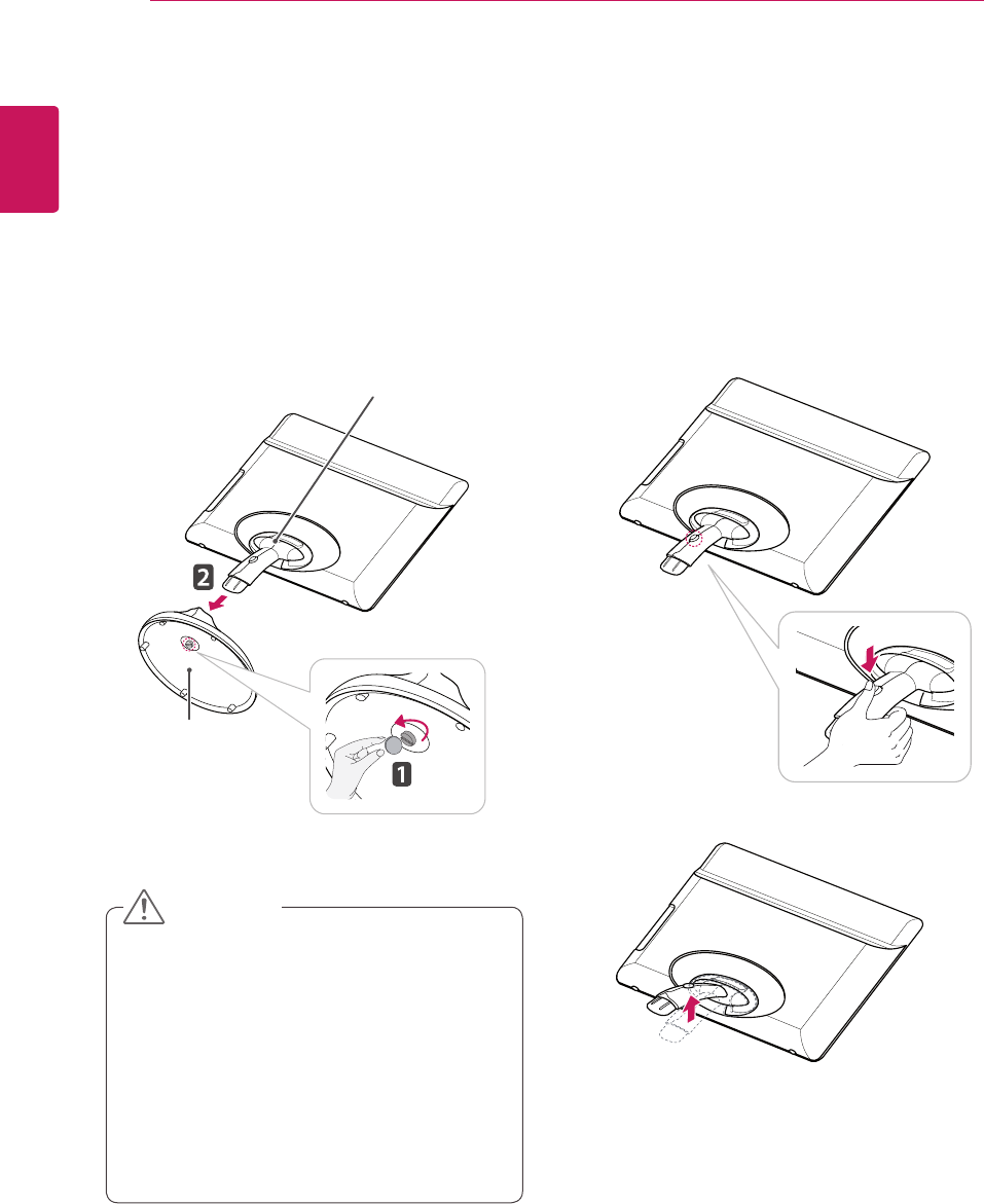
Detaching the stand base
1 Place the monitor's screen face down.
To protect the screen from scratches, cover the
surface with a soft cloth.
Adjusting the stand body
1 Place the monitor's screen face down.
To protect the screen from scratches, cover the
surface with a soft cloth.
2 Using a coin, turn the screw in the stand base
counterclockwise. Detach the stand base from
the stand body.
2 Press the button as shown and pull the stand
body up.
CAUTION
Stand Body
Stand Base
9
ENG
ENGLISH
ASSEMBLING AND PREPARING
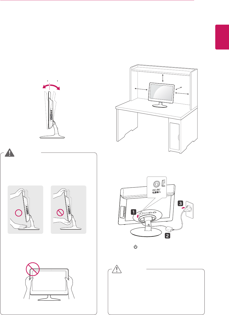
Mounting on a table
1 Lift the monitor and place it on the table in an
upright position.
Install at least 10 cm away from the wall to
ensure sufficient ventilation.
2 Connect the adaptor to the monitor, then plug
the power cord into the wall outlet.
3 Press the (Power) button on the front of the
monitor to turn on the monitor.
10 cm
10 cm
10 cm
10 cm
yUnplug the power cord prior to moving or
installing the monitor. There is risk of electric
shock.
yWhen you connect the DC jack to the moni-
tor, ensure it is inserted tightly to prevent it
from coming loose.
CAUTION
Adjusting the angle
1 Place the monitor mounted on the stand base
in an upright position.
2 Adjust the angle of the screen. The angle of the
screen can be adjusted up to 15° forwards and
5° backwards for a comfortable viewing experi-
ence.
yTo avoid injury to the fingers when adjusting
the screen, do not hold the lower part of the
monitor's frame as illustrated below.
yBe careful not to touch or press the screen
area when adjusting the angle of the monitor.
15- 5
Front Side Rear Side
15- 5
WARNING
10
ENG
ENGLISH
ASSEMBLING AND PREPARING
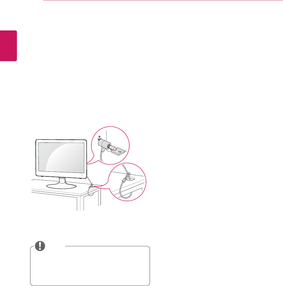
Using the Kensington locking
device
The connector for the Kensington lock is located
on the rear of the monitor.
For more information on installation and usage,
refer to the Kensington lock user manual or visit
the website at http://www.kensington.com.
Connect the monitor to the table with the Kensing-
ton lock cable.
yUsing the Kensington lock is optional. The
accessories can be purchased at your local
electronics store.
NOTE
11
ENG
ENGLISH
ASSEMBLING AND PREPARING
Installing the wall mount plate
This monitor has a VESA compatible mount on the
back. Most mounts will require an LG mounting
plate.
Detaching the stand body
1 Place the monitor's screen face down. To
protect the screen from scratches, cover the
surface with a soft cloth.
2 Using a screwdriver, Remove the Cover and
detach from the monitor.
3 Using a screwdriver, remove the five screws
and detach the stand from the monitor.
1 Place the monitor's screen face down. To
protect the screen from scratches, cover the
surface with a soft cloth.
2 Place the wall mount plate on the monitor and
align it with the screw holes on the monitor.
3 Using a screwdriver, tighten the four screws to
fix the plate onto the monitor.
yThe wall mount plate is sold separately.
yFor more information on the installation, refer
to the wall mount plate's installation guide.
Wall Mount Plate
NOTE
12
ENG
ENGLISH
ASSEMBLING AND PREPARING
10 cm
10 cm
10 cm 10 cm
yUnplug the power cord before moving or in-
stalling the monitor to avoid electric shocks.
yThe wall mount kit includes the installation
guide and necessary parts.
yThe wall mounting bracket is optional. The
accessories can be purchased at your local
retail store.
yThe length of the screw may differ for each
wall mounting bracket. Ensure the correct
length of the screw is used.
yFor more information, please refer to the user
manual for the wall mounting bracket.
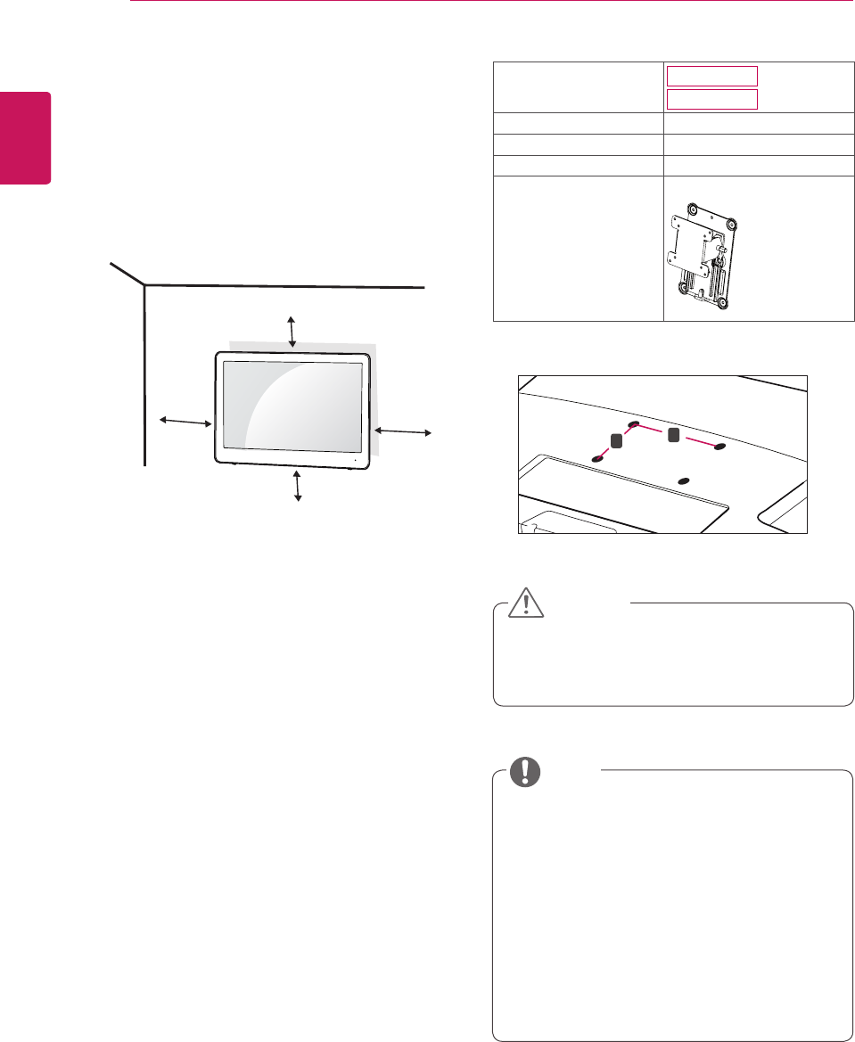
Model N195WU
N225WU
VESA (A x B) 75 x 75
Stand Screw M4
Required Screw 4
Wall Mount Plate
(Optional)
RW120
Mounting on a wall
Install the monitor at least 10 cm away from the
wall and leave about 10 cm of space at each side
of the monitor to ensure sufficient ventilation. De-
tailed installation instructions can be obtained from
your local retail store. Please refer to the manual
to install and set up a tilting wall mounting bracket.
CAUTION
NOTE
If you intend to mount the Monitor set to a wall,
attach Wall mounting interface (optional parts) to
the back of the set.
When you install the Monitor set using the wall
mounting interface (optional parts), attach it
carefully so it will not drop.
1 Please, Use the screw and wall mount interface
in accordance with VESA Standards.
2 If you use screw longer than standard, the
monitor might be damaged internally.
3 If you use improper screw, the product might be
damaged and drop from mounted position. In
this case, LG Electronics is not responsible for it.
4 VESA compatible.
5 Please use VESA standard as below.
y784.8 mm (30.9 inch) and under
* Wall Mount Pad Thickness : 2.6 mm
* Screw : Φ 4.0 mm x Pitch 0.7 mm x
Length 10 mm
y787.4 mm (31.0 inch) and above
* Please use VESA standard wall mount pad
and screws.
A
B
yVESA (A x B)
13
ENG
ENGLISH
USING THE MONITOR SET
USING THE MONITOR SET
Using Primary Station
yThis monitor supports the *Plug and Play
feature.
*Plug and Play: A feature that allows you to
add a device to your computer, without having
to reconfigure anything or install any manual
drivers.
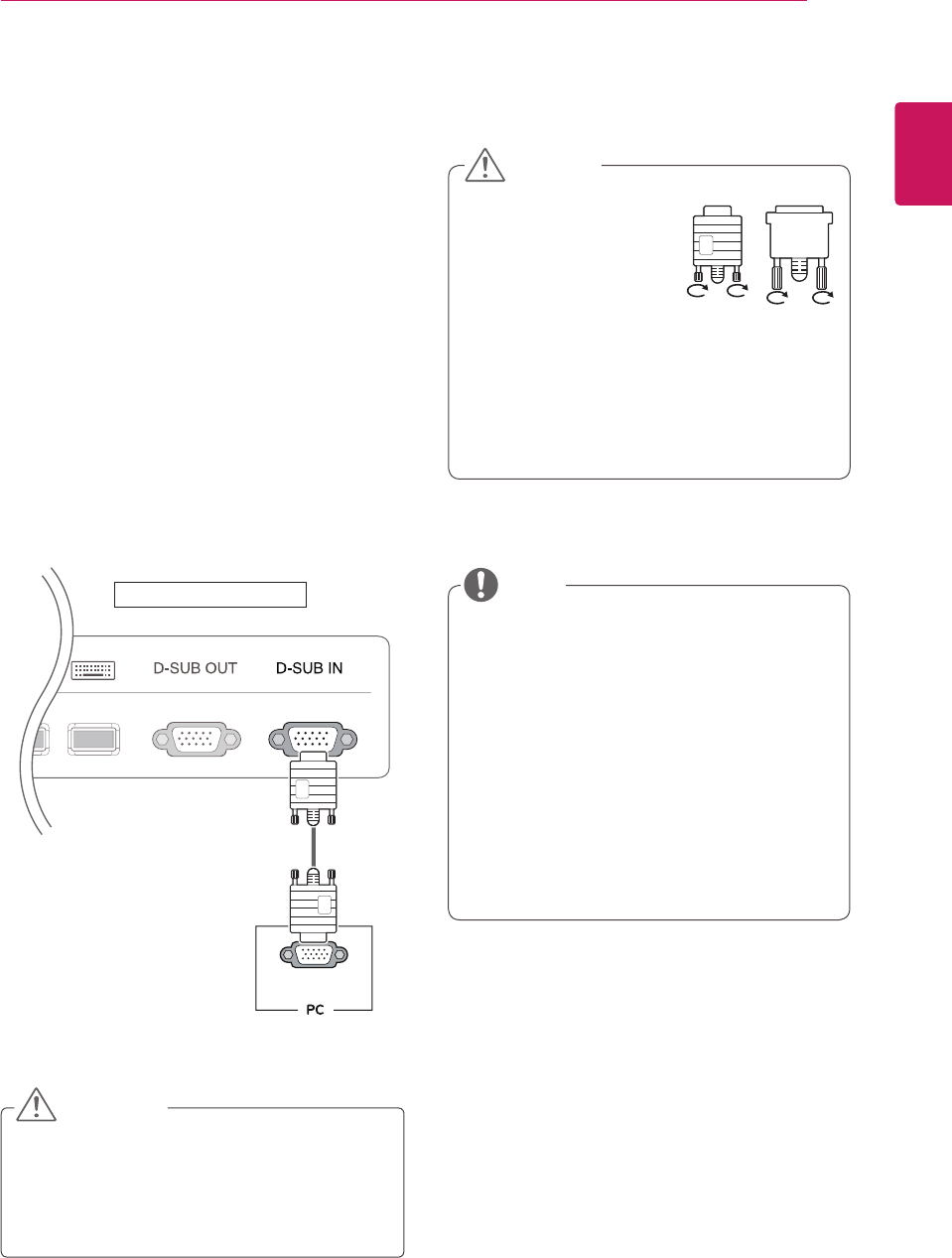
D-SUB IN connection - PC
D-SUB IN transfers analog video signals from the
PC to the monitor.
Connect the monitor to the PC using the provided
15-pin D-SUB signal cable as illustrated below.
RGB OUT
HURB
PC
Back of the product.
yTo connect the monitor to a computer, use
the appropriate signal cable (D-SUB).
yA converter can be used to convert the DVI-I
input signal to D-SUB input signal.
yWhen connecting the power cord to the out-
let, use a grounded (3-hole) multi-socket or a
grounded wall outlet.
yThe monitor may flicker when turned on in an
area of low temperature. This is normal.
ySometimes red, green or blue spots may ap-
pear on the screen. This is normal.
yConnect the input signal
cable and tighten in the
direction of the arrow. To
prevent disconnection
secure the cable tightly.
yDo not press on the screen for a prolonged
time. This may cause image distortion.
yDo not display a still image on the screen
for a prolonged time. This may cause image
retention. If possible, use the screen saver.
CAUTION
CAUTION
NOTE
yThe D-SUB OUT port is used to output the
image signals inputted from the USB port.
The D-SUB OUT port is not supported if the
D-SUB IN port is being used.
14
ENG
ENGLISH
USING THE MONITOR SET
NOTE
NOTE
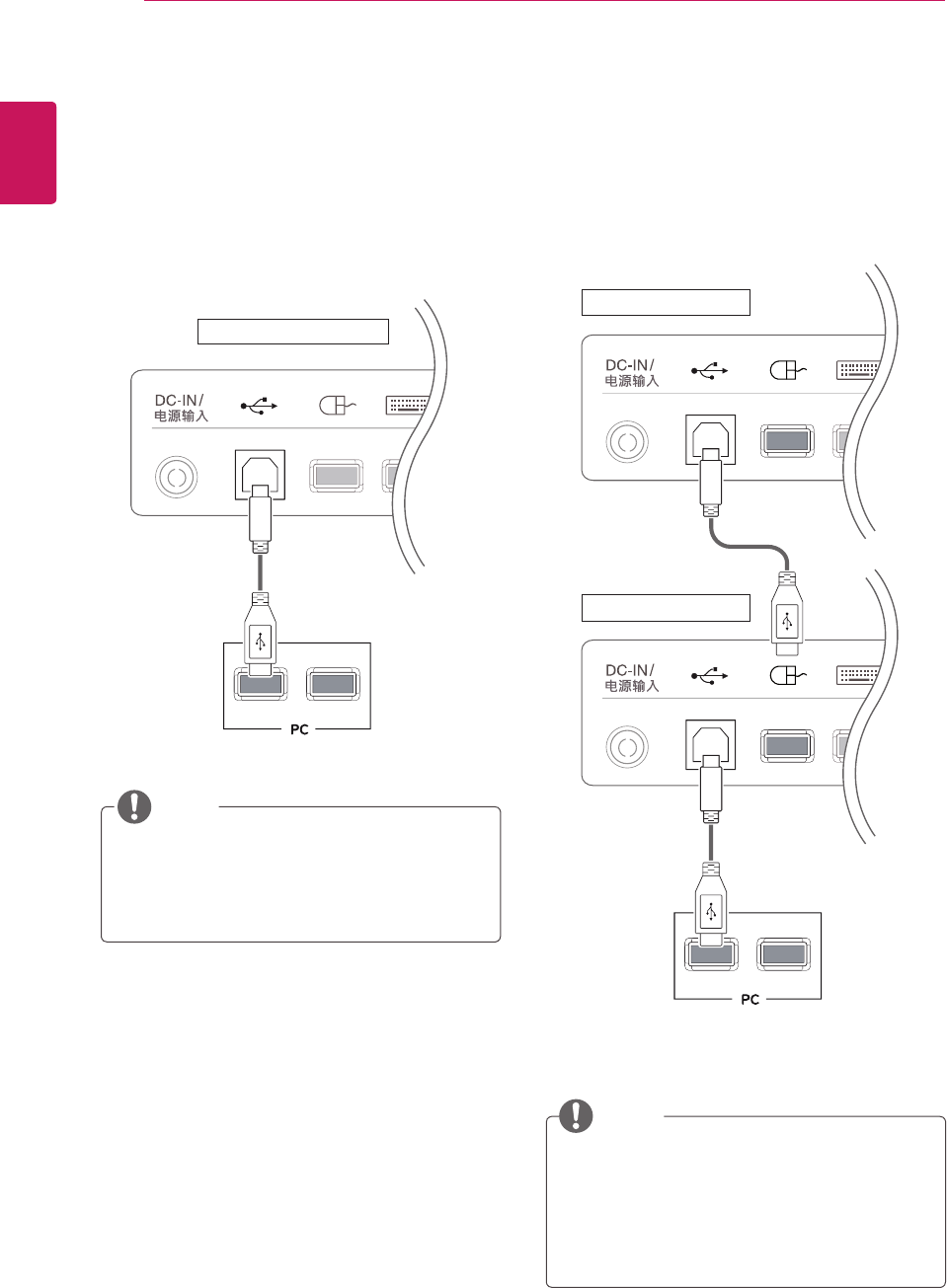
Using Standard Stations
USB cable connection - PC
D-SUB IN transfers analog video signals from the
PC to the monitor.
Connect the monitor to the PC using the provided
15-pin D-SUB signal cable as illustrated below.
Back of the product.
USB cable connection to Daisy
Chain
D-SUB IN transfers analog video signals from the
PC to the monitor.
Connect the monitor to the PC using the provided
15-pin D-SUB signal cable as illustrated below.
Back of the product.
Back of the product.
yIf the USB cable provided is not long enough,
you may need to purchase an additional
extension cable. (maximum length 5 m)
yUp to 2 monitors can be connected by daisy-
chaining, as shown above.
yWhen using a daisy chain, connect the
mouse to the USB port on the left at the back
of the monitor.
15
ENG
ENGLISH
USING THE MONITOR SET
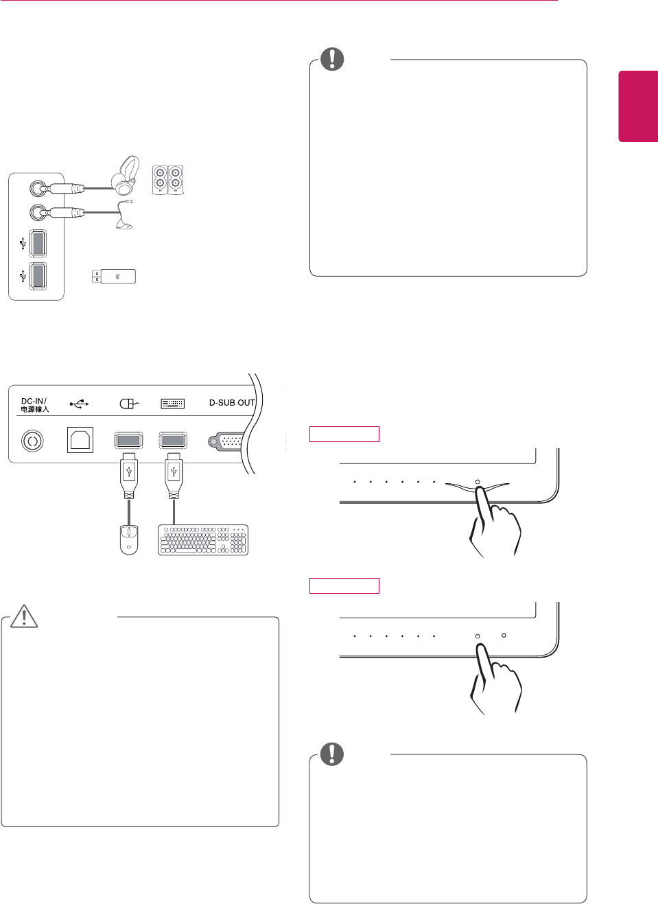
Peripheral device connection
Connect peripheral devices to the monitor using
USB, headphone, speaker, and microphone ports.
Right
Bottom
yIf a PS2 keyboard and mouse are connected
to the PC audio device in a multi-computing
environment (normal mode), the sound
output will be supported through the analog
port. If a USB keyboard and mouse are con-
nected, the sound output will be supported
through the USB headphones. If using a PC
without a PS2 keyboard/mouse input port,
please use a USB audio (headphones) for
sound output.
yPeripheral devices are sold separately.
yThe USB ports on the bottom of the moni-
tor can be used to connect the keyboard,
mouse, and other USB devices. But, USB
ports on the right of the monitor can't be used
to connect the keyboard.
yHeadphones, speakers or microphone may
not work normally, depending on the server
PC settings.
yVirtual solutions may affect the functions or
speed of the specific USB storage device.
NOTE
yWhat is "Self Image Adjustment"? This func-
tion runs when the monitor is connected for
the first time and performs automatic image
adjustment for each signal (only available for
analog [D-SUB input] signals) to provide an
optimal screen display.
Self Image Adjustment
Press the power button on the front to turn on
the monitor. When powered on, the "Self Image
Adjustment" function will run automatically (only
available for analog [D-SUB input] signals).
NOTE
CAUTION
N195WU
N225WU
16
ENG
ENGLISH
CUSTOMIZING SETTINGS
MENU SMART+ VOLUME INPUT EXIT
MONITOR SETUP
AUTO
Front Side Buttons
CUSTOMIZING SETTINGS
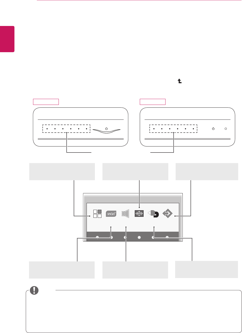
Accessing The Main Menus
1 Press any button on the front of the monitor to display the MONITOR SETUP OSD menu.
2 Press to select the desired menu item.
3 To change the settings of the selected item press the buttons on the front of the monitor.
To return to the upper menu or set other menu items, use the up arrow ( ) button.
4 Select EXIT to leave the OSD menu.
MENU (See p.17)
Sets the screen options.
EXIT (See p.6)
Exits the OSD menu.
AUTO (See p.24)
Optimizes the resolution.
/ Disconnects from the server.
Different menu items are enabled depending on the type of input signal.
yD-SUB Input: MENU, SMART+, AUTO, INPUT, EXIT
yUSB Input: MENU, SMART+, VOLUME, INPUT, EXIT
yThe language of the monitor's OSD menu and that of the OSD menu illustrated in the CD-ROM
manual may be different.
SMART+ (See p.22)
Sets the Auto Bright (Only N195WU
model) ,Original Ratio.
VOLUME (See p.20)
Sets the volume.
INPUT (See p.6)
Sets the external input.
NOTE
N195WU N225WU
17
ENG
ENGLISH
CUSTOMIZING SETTINGS
MENU Settings
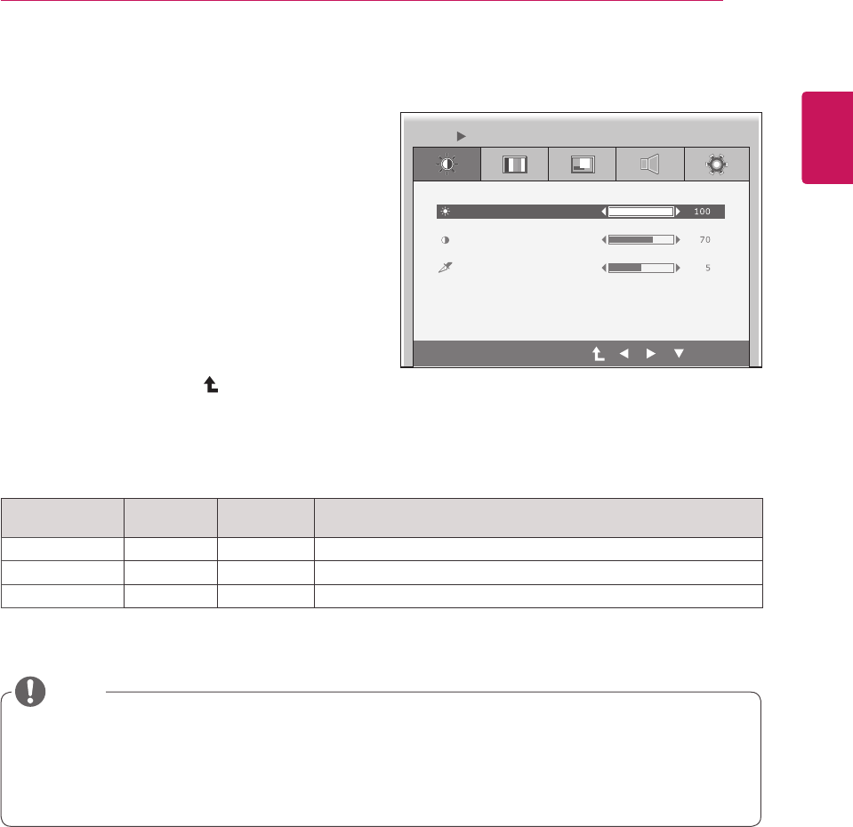
Picture
1 Press any button on the front of the monitor to
display the MONITOR SETUP OSD menu.
2 Press the MENU button to display the options
in the OSD menu.
3 Set the options by pressing the buttons on the
front of the monitor.
4 Select EXIT to leave the OSD menu.
To return to the upper menu or set other menu
items, use the up arrow ( ) button.
Each option is explained below.
Menu Analog
(D-SUB) USB Description
BRIGHTNESS o o Sets the brightness of the screen.
CONTRAST o o Sets the contrast of the screen.
SHARPNESS o o Sets the sharpness of the screen.
y If the screen is not displayed properly after adjusting the settings, use the "FACTORY RESET" op-
tion to revert back to the factory default settings. If necessary, enable the "WHITE BALANCE" option
again. This option is enabled only for analog (D-SUB) signals.
yAnalog: D-SUB (analog signal) input. USB: Internal signal through the USB.
BRIGHTNESS
CONTRAST
MENU PICTURE
SHARPNESS
EXIT
NOTE
18
ENG
ENGLISH
CUSTOMIZING SETTINGS
Menu Analog
(D-SUB) USB Description
COLOR TEMP o o Allows PRESET or USER to be selected.
PRESET
o o
WARM Sets the screen color to a reddish tone.
MEDIUM Sets the screen color between the reddish and bluish
tone.
COOL Sets the screen color to a bluish tone.
USER o o You can customize the picture color using Red, Green, and Blue
colors.
GAMMA
o o
Sets the clarity of the screen.
The gamma value can be set to 0, 1 or 2, from darker to brighter
screen colors respectively.
yAnalog: D-SUB (analog signal) input. USB: Internal signal through the USB.
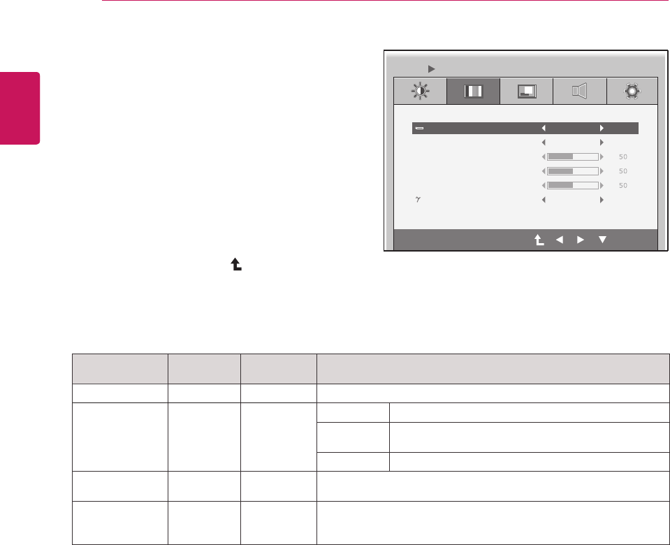
Color
1 Press any button on the front of the monitor to
display the MONITOR SETUP OSD menu.
2 Press the MENU button to display the options
in the OSD menu.
3 Set the options by pressing the buttons on the
front of the monitor.
4 Select EXIT to leave the OSD menu.
To return to the upper menu or set other menu
items, use the up arrow ( ) button.
COLOR TEMP PRESET
PRESET
GAMMA GAMMA 1
RED
GREEN
BLUE
WARM
MENU COLOR
EXIT
Each option is explained below.
19
ENG
ENGLISH
CUSTOMIZING SETTINGS
Menu Analog
(D-SUB) USB Description
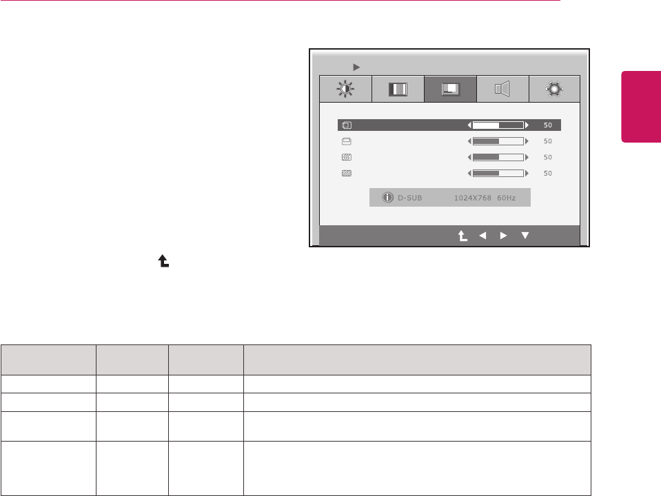
HORIZONTAL oxMoves the display area left or right.
VERTICAL oxMoves the display area up or down.
CLOCK oxIf vertical lines are shown on the screen, adjust the frequency to mini-
mize the lines and adjust the screen's horizontal width.
PHASE
ox
Adjusts the focus of the screen's image.
Use when frequencies are shown on the screen or when the text ap-
pears overlapped. For optimal results, use this option after adjusting
the "CLOCK" option.
yAnalog: D-SUB (analog signal) input. USB: Internal signal through the USB.
Display
1 Press any button on the front of the monitor to
display the MONITOR SETUP OSD menu.
2 Press the MENU button to display the options
in the OSD menu.
3 Set the options by pressing the buttons on the
front of the monitor.
4 Select EXIT to leave the OSD menu.
To return to the upper menu or set other menu
items, use the up arrow ( ) button.
HORIZONTAL
EXIT
VERTICAL
CLOCK
PHASE
MENU DISPLAY
Each option is explained below.
20
ENG
ENGLISH
CUSTOMIZING SETTINGS
EXIT
MENU VOLUME
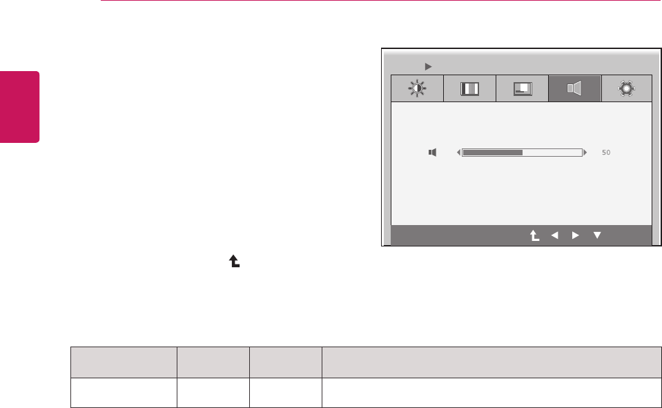
Menu Analog
(D-SUB) USB Description
VOLUME xoTo adjust the volume of headphone/Speaker.
(Only for USB input)
Volume
1 Press any button on the front of the monitor to
display the MONITOR SETUP OSD menu.
2 Press the MENU button to display the options
in the OSD menu.
3 Set the options by pressing the buttons on the
front of the monitor.
4 Select EXIT to leave the OSD menu.
To return to the upper menu or set other menu
items, use the up arrow ( ) button.
Each option is explained below.
yAnalog: D-SUB (analog signal) input. USB: Internal signal through the USB.
21
ENG
ENGLISH
CUSTOMIZING SETTINGS
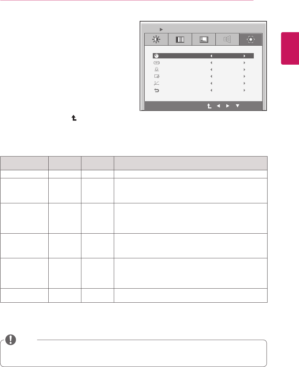
Menu Analog
(D-SUB) USB Description
LANGUAGE o o Sets the menu screen to the desired language.
POWER OFF OSD
xo
Enables or disables the power off message when turning power off.
If it is set to "Off", the power off message is not displayed while
maintaining client connection.
If it is set to "On", the power off message is displayed. (See p.6)
POWER
INDICATOR
o o
Use this function to set the power indicator on the front side of the
monitor to ON or OFF.
If you set OFF, it will be turned off.
If you set ON at any time, the power indicator will automatically be
turned on.
BUTTON
INDICATOR o o
Use this function to set the control key indicator on the front side of
the monitor to ON or OFF.
If you set OFF, it will be turned off.
If you set ON, it will be turned on.
WHITE BALANCE
ox
If the video card output is different from the specified level, the color
may appear to have altered due to the video signal distortion. The
white balance adjusts the output signal level to correspond to that of
the standard signal, thus providing optimal display. Run this option
when the screen displays an image with both white and black.
FACTORY RESET o o Resets the screen to the factory default settings. Note that the lan-
guage option will not be reset.
yAnalog: D-SUB (analog signal) input. USB: Internal signal through the USB.
Others
1 Press any button on the front of the monitor to
display the MONITOR SETUP OSD menu.
2 Press the MENU button to display the options
in the OSD menu.
3 Set the options by pressing the buttons on the
front of the monitor.
4 Select EXIT to leave the OSD menu.
To return to the upper menu or set other menu
items, use the up arrow ( ) button.
LANGUAGE
EXIT
English
POWER OFF OSD ON
ON
ON
NO
NO
POWER INDICATOR
BUTTON INDICATOR
WHITE BALANCE
FACTORY RESET
MENU OTHERS
Each option is explained below.
yWhen connecting monitors in a daisy chain, select "Off" for the "Power Off OSD" option.
NOTE
22
ENG
ENGLISH
CUSTOMIZING SETTINGS
Menu Analog
(D-SUB) USB Description
ON
o o
If select on,it automatically controls the brightness of display to best
suit the surrounding working environment,providing the optimal
viewing condition and maximized user convenience.
OFF o o If select off,auto brightness is off.
SMART+ Settings
Auto Bright
(Only N195WU model)
1 Press any button on the front of the monitor to
display the MONITOR SETUP OSD menu.
2 Press the SMART+ button to display the op-
tions in the OSD menu.
3 Set the options by pressing the buttons on the
front of the monitor.
4 Select EXIT to leave the OSD menu.
To return to the upper menu or set other menu
items, use the up arrow ( ) button.
Each option is explained below.
yAnalog: D-SUB (analog signal) input. USB: Internal signal through the USB.
EXIT
SMART+ AUTO BRIGHT
ON OFF
23
ENG
ENGLISH
CUSTOMIZING SETTINGS
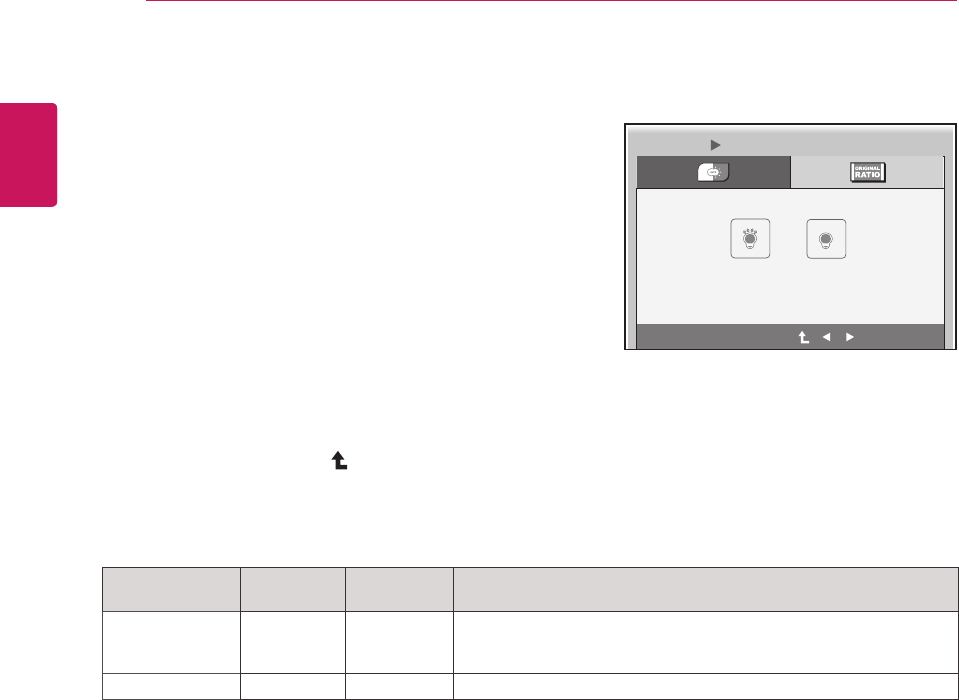
Menu Analog
(D-SUB) USB Description
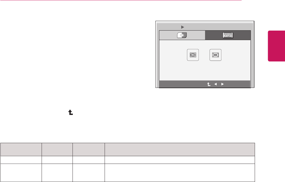
WIDE o o Switch to full screen mode according to input image signal.
ORIGINAL
o o
Change the input image signal ratio to original.
This function works only if input resolution is lower than Monitor set
ratio (16:9).
Original Ratio
1 Press any button on the front of the monitor to
display the MONITOR SETUP OSD menu.
2 Press the SMART+ button to display the op-
tions in the OSD menu.
3 Set the options by pressing the buttons on the
front of the monitor.
4 Select EXIT to leave the OSD menu.
To return to the upper menu or set other menu
items, use the up arrow ( ) button.
Each option is explained below.
yAnalog: D-SUB (analog signal) input. USB: Internal signal through the USB.
EXIT
SMART+ ORIGINAL RATIO
WIDE ORIGINAL
24
ENG
ENGLISH
CUSTOMIZING SETTINGS
1 Press any button on the front of the monitor to dis-
play the MONITOR SETUP OSD menu.
2 Press the AUTO button to automatically adjust the
screen.
3 Select EXIT to leave the OSD menu.
To return to the upper menu or set other menu items,
use the up arrow ( ) button.
Pressing the AUTO button allows the monitor to automatically optimize the screen to the current display
mode.
If you are not satisfied with the optimized screen, you can manually adjust the position of the display area,
frequency, phase and sharpness in the OSD menu.
(Only available for D-SUB [analog] signals. Note that the sharpness setting is only available for digital sig-
nals.)
PROCESSING AUTO IMAGE ADJUSTMENT
FOR OPTIMAL DISPLAY
CHANGE RESOLUTION TO 1366 x 768
PROCESSING AUTO IMAGE ADJUSTMENT
FOR OPTIMAL DISPLAY
CHANGE RESOLUTION TO 1920 x 1080
yWhat is "Auto Image Adjustment"? The Auto Image Adjustment option allows you to improve the pic-
ture quality if the screen is dimmed, if the text appears blurred or spread, if the screen flickers or if the
display area is not centered after adjusting the resolution. (Only available for D-SUB [analog] signals.)
NOTE
AUTO Settings : D-SUB Input
N195WU
N225WU
25
ENG
ENGLISH
Troubleshooting
TROUBLESHOOTING
Nothing is displayed on the screen
Is the monitor's power cord
plugged in?
yCheck if the power cord is correctly plugged in to the outlet.
Is the power indicator on?
yCheck the power indicator.
Is the power indicator displaying
as purple?
yAdjust the brightness and the contrast.
Is the power indicator blinking?
yIf the monitor is in power saving mode, move the mouse or press any
key on the keyboard to switch the display on.
yCheck if the computer is turned on.
Is the "OUT OF RANGE" mes-
sage displayed?
yThis occurs when signals transferred from the PC (video card) are out
of the horizontal or vertical frequency range of the monitor. Please see
the "Product Specification" section of this manual to set the appropri-
ate frequency.
Is the "CHECK SIGNAL CA-
BLE" message is displayed?
yThis is displayed when the signal cable between the PC and the moni-
tor is missing or disconnected. Check the cable and reconnect.
The "OSD LOCKED" message is displayed.
Is the "OSD LOCKED" mes-
sage displayed when the MENU
button is pressed?
yThe OSD lock feature is enabled to prevent undesired modification
of the OSD settings. Press and hold the MENU button for a couple of
seconds to unlock the OSD. (The "OSD UNLOCKED" message will be
displayed.)
The screen retains an image.
Does image sticking occur even
when the monitor is turned off?
yDisplaying a still image for a prolonged time may cause damage to the
screen, resulting in the retention of the image.
yUse a screen saver to protect the screen when using the monitor for a
prolonged period of time.
yVertical Frequency: In order to display an image, the screen must be refreshed dozens of times per
second like a fluorescent lamp. The number of times the screen is refreshed per second is called
vertical frequency or refresh rate and is represented by Hz.
yHorizontal Frequency: The time it takes to display one horizontal line is called the horizontal cycle.
The number of horizontal lines displayed in one second can be calculated by dividing one by the hori-
zontal cycle. This is called horizontal frequency and is represented by kHz.
NOTE
26
ENG
ENGLISH
Troubleshooting
The image is displayed abnormally.
Does the display area appear
uncentered?
Pressing the AUTO button will automatically optimize the screen to the
current display mode.
If you are not satisfied with the optimized screen, you can manually
adjust the POSITION option in the OSD menu.
Does the screen exhibit vertical
lines?
Pressing the AUTO button will automatically optimize the screen to the
current display mode.
If you are not satisfied with the optimized screen, you can manually
adjust the FREQUENCY option in the OSD menu.
Does the screen display hori-
zontal frequencies, or does the
text appear blurred?
Pressing the AUTO button will automatically optimize the screen to the
current display mode.
If you are not satisfied with the optimized screen, you can manually
adjust the PHASE option in the OSD menu.
yCheck if the video card's resolution or frequency is within the range allowed by the monitor and set to
the recommended (optimal) resolution in Control Panel > Display > Settings.
yFailing to set the video card to the recommended (optimal) resolution may result in blurred text, a
dimmed screen, a truncated display area or misalignment of the display.
yThe configuration procedure may differ depending on your computer and/or operating system. Also,
some video cards may not support certain resolutions. If this is the case, contact the computer or
video card manufacturer for assistance.
yThe AUTO option is only available for D-SUB (analog) signals.
yThe recommended monitor resolution (optimized resolution) of the WMS 2011 operating system is
usually 1364 x 768, but the actual monitor resolution is 1366 x 768. This is not a monitor malfunction;
it occurs due to the characteristics of the operating system. (Only N195WU model)
The display color is abnormal.
Does the display color appear
discolored (16 color)?
ySet the color to 24 bit (true color) or higher. In Windows, go to Control
Panel > Display > Settings > Color Quality.
Does the display color appear
unstable or in monochrome?
yCheck if the signal cable is connected properly. Re-connect the cable
or re-insert the PC's video card.
Are there spots on the screen?
yWhen using the monitor, pixilated spots (red, green, blue, white or
black) may appear on the screen. This is normal for the LCD screen.
It is not an error nor is it related to the monitor's performance.
NOTE
27
ENG
ENGLISH
Product Specication
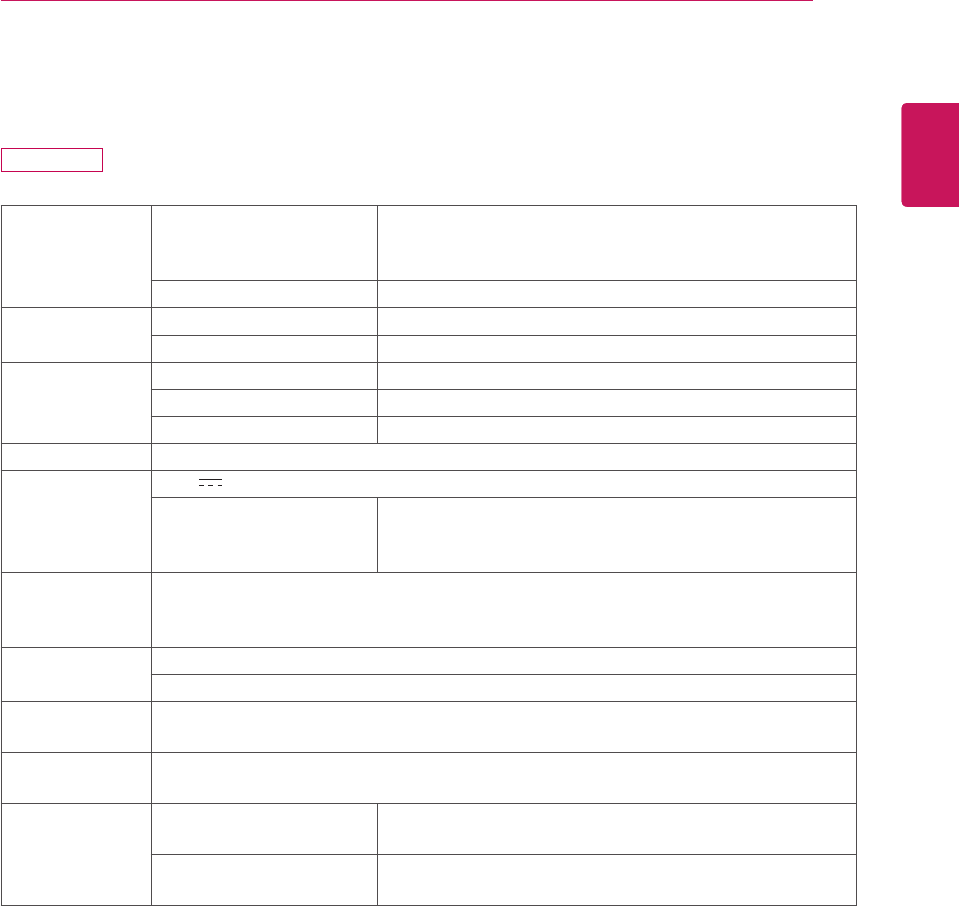
PRODUCT SPECIFICATION
LCD Screen Type 470.1 mm (18.51 inch) TFT (Thin Film Transistor)
LCD (Liquid Crystal Display) Screen
Diagonal length of the screen: 470.1 mm
Pixel Pitch 0.30 mm x 0.30 mm
Resolution Maximum Resolution 1366 x 768 @ 60 Hz
Recommended Resolution 1366 x 768 @ 60 Hz
Video Signal Horizontal Frequency 30 kHz to 66 kHz
Vertical Frequency 57 Hz to 63 Hz
Synchronization Separate Sync / USB
Input Connector 15-pin D-SUB (Analog), USB
Power 19 V 1.7 A
Power Consumption On Mode: 22 W (Typical)
Power Saving Mode ≤ 1 W / 7 W
Off Mode ≤ 1 W
AC/DC Adapter Manufacturer : LITE-ON, Model PA-1650-68
Input: AC 100-240 V
Output: DC 19 V
Dimension Monitor Size (Width x Height x Depth)
457.9 mm x 369.5 mm x 197.9 mm
Weight (Without
Packaging)
2.6 kg
Stand Angle
Adjustment
Forwards/Backwards: -5° to 15°
Environment
Condition
Operating Condition Temperature: 10°C to 35°C;
Humidity: 10% to 80%
Storing Condition Temperature: -20°C to 60°C;
Humidity: 5% to 90%
The specifications are subject to change without notice.
N195WU
28
ENG
ENGLISH
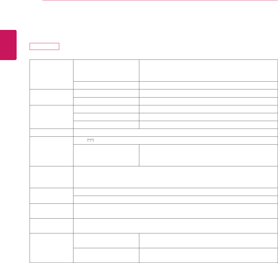
Specications
LCD Screen Type 546.8 mm (21.53 inch) TFT (Thin Film Transistor)
LCD (Liquid Crystal Display) Screen
Diagonal length of the screen: 546.8 mm
Pixel Pitch 0.248 mm x 0.248 mm
Resolution Maximum Resolution 1920 x 1080 @ 60 Hz
Recommended Resolution 1920 x 1080 @ 60 Hz
Video Signal Horizontal Frequency 30 kHz to 68 kHz
Vertical Frequency 57 Hz to 63 Hz
Synchronization Separate Sync / USB
Input Connector 15-pin D-SUB (Analog), USB
Power 19 V 3.2 A
Power Consumption On Mode: 28 W (Typical)
Power Saving Mode ≤ 1 W / 7 W
Off Mode ≤ 1 W
AC/DC Adapter Manufacturer : LITE-ON, Model PA-1650-68
Input: AC 100-240 V
Output: DC 19 V
Dimension Monitor Size (Width x Height x Depth)
524.6 mm x 406.9 mm x 198 mm
Weight (Without
Packaging)
3.1 kg
Stand Angle
Adjustment
Forwards/Backwards: -5° to 15°
Environment
Condition
Operating Condition Temperature: 10°C to 35°C;
Humidity: 10% to 80%
Storing Condition Temperature: -20°C to 60°C;
Humidity: 5% to 90%
The specifications are subject to change without notice.
N225WU
29
ENG
ENGLISH
Product Specication
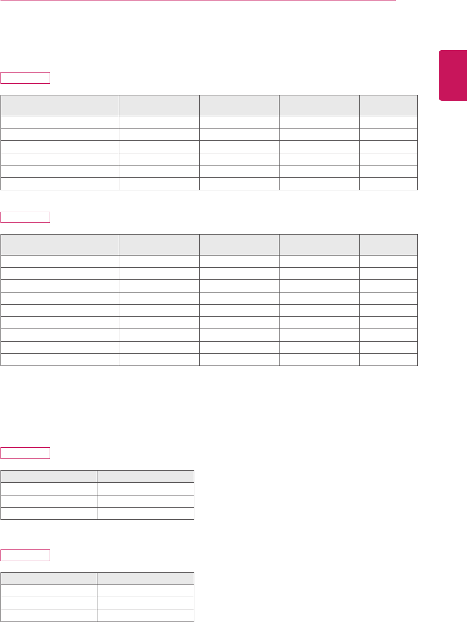
Preset Mode
Preset Mode Horizontal
Frequency (kHz)
Vertical
Frequency (Hz) Polarity (H/V) Remark
720 x 400 31.468 70 -/+
640 x 480 31.469 60 -/-
800 x 600 37.879 60 +/+
1024 x 768 48.363 60 -/-
1360 x 768 47.712 60 +/+
1366 x 768 47.712 60 +/+
Preset Mode Horizontal
Frequency (kHz)
Vertical
Frequency (Hz) Polarity (H/V) Remark
720 x 400 31.468 70 -/+
640 x 480 31.469 60 -/-
800 x 600 37.879 60 +/+
1024 x 768 48.363 60 -/-
1360 x 768 47.712 60 +/+
1366 x 768 47.712 60 +/+
1680 x 1050 64.674 60 -/-
1680 x 1050 65.290 60 -/+
1920 x 1080 67.500 60 +/+
Power Indicator
Mode LED Color
On Mode Purple
Power Saving Flashing Purple
Off Mode Off
Mode LED Color
On Mode Blue
Power Saving Flashing Blue
Off Mode Off
N195WU
N195WU
N225WU
N225WU
30
ENG
ENGLISH
Proper Posture
PROPER POSTURE
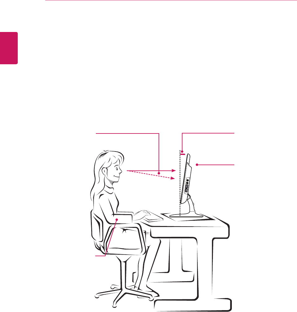
Proper posture for using the monitor
Adjust the angle so that the screen is slightly lower than your eyes.
yUsing the monitor for a prolonged period of time can cause eye fatigue. Take a 10-minute break every
hour.
yThe stand is designed to best support the monitor when the optimal conditions are selected.
Adjust the angle of the monitor from -5° to 15° to obtain the best view of the screen.
You should be
looking
slightly down at
the screen.
Place your hands gen-
tly on the keyboard,
keeping your arms bent
at the elbows
and extended horizon-
tally in front of you.
Adjust the angle
from -5° to 15°
so that there is no re-
flection
or glare from the
screen.

Make sure to read the Safety Precautions
before using the product.
Keep the Owner's Manual(CD) in an
accessible place for future reference.
The model and serial number of the SET
is located on the back and one side of the
SET. Record it below should you ever need
service.
MODEL
SERIAL
As an ENERGY STAR Partner LGE U. S. A.,Inc. has
determined that this product meets the ENERGY STAR
guidelines for energy efficiency.
ENERGY STAR is a set of power-saving
guidelines issued by the U.S. Environmental
Protection Agency(EPA).