LG Electronics USA PCRCUDT2 WLAN module User Manual EMISSION TEST REPORT
LG Electronics USA WLAN module EMISSION TEST REPORT
UserManual.wiki
>
LG Electronics USA
>
PCRCUDT2 User Manual
User Manual
Navigation menu
Upload a User Manual
Namespaces
Wiki Guide
HTML
PDF
Info
Views
User Manual
Discussion / Help
Navigation
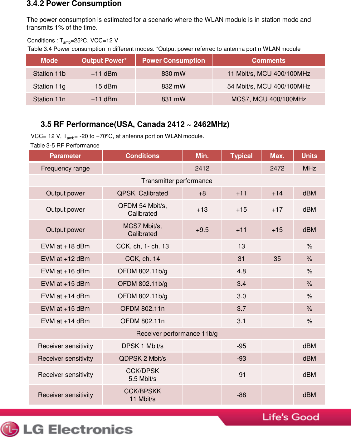
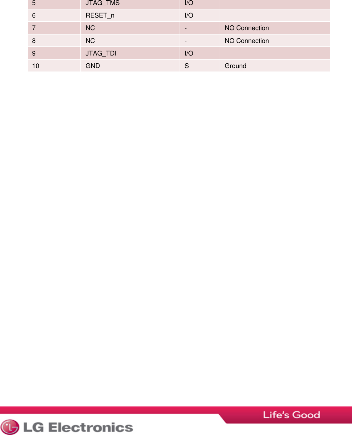
![RatingMin.Max.UnitSupply voltage015VInput RF level10dBmStorage temperature-50+125°CRatingMin.Typ.Max.UnitSupply Voltage VCC5.0-12.0VOperating temperature WLAN module-20+25+70ㅇCModeConditionsParameterVoltageMin.Typ.Max.UnitAll modesPeakVCC12 V100mATX [802.11b], 11 Mbps25°CVCC12 V100mATX [802.11g], 54 Mbps25°CVCC12 V83mATX [802.11n], MCS725°CVCC12 V73mARX [802.11b], 11 Mbps25°CVCC12 V47mARX [802.11g], 54 Mbps25°CVCC12 V47mARX [802.11n], MCS725°CVCC12 V47mA3. ELECTRICAL DATA3.1 Absolute maximum ratingsTable 3-1 Absolute maximum ratings. Exceeding any of the maximum ratings, even briefly lead to deterioraton inPerformance or even destruction. Values indicates condition applied one at the time3.2 Electro Static Discharge (ESD)WLAN module withstands ESD voltages up to 2000 V HBM (Human Body Model)According to JESD22-A114 and up to 300 V MM (Machine Model) according to JESD22-A115.3.3 Recommended operationg conditionsTable 3-2 Recommended operating conditionsTable 3-3 Current consumption in different modes MCU running at 400MHz and system clock at 100MHz.3.4 Power Consumption3.4.1 Current Consumption](https://usermanual.wiki/LG-Electronics-USA/PCRCUDT2/User-Guide-1911954-Page-7.png)