LG Electronics USA PCRCUDT4 WLAN Module User Manual H User s Manual
LG Electronics USA WLAN Module H User s Manual
UserManual.wiki
>
LG Electronics USA
>
PCRCUDT4 User Manual
User Manual
Navigation menu
Upload a User Manual
Namespaces
Wiki Guide
HTML
PDF
Info
Views
User Manual
Discussion / Help
Navigation
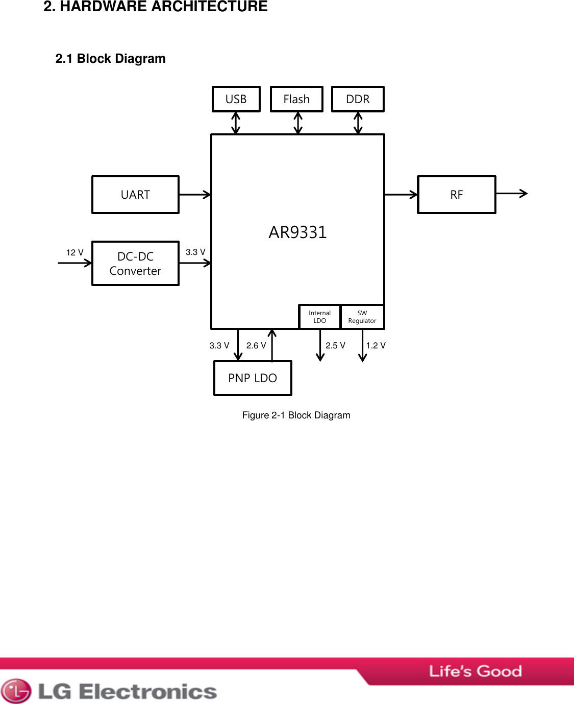
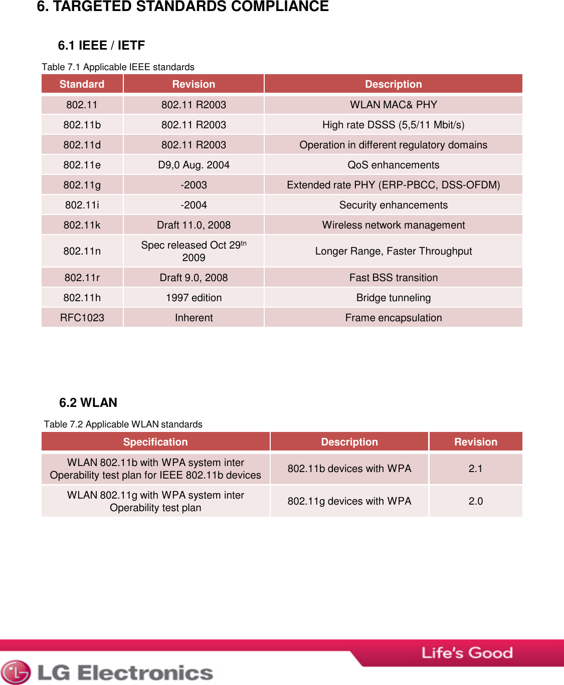
![Rating Min. Max. Unit Supply voltage 0 15 V Input RF level 10 dBm Storage temperature -50 +125 °C Rating Min. Typ. Max. Unit Supply Voltage VCC 5.0 - 12.0 V Operating temperature WLAN module -20 +25 +70 ㅇC Mode Conditions Parameter Voltage Min. Typ. Max. Unit All modes Peak VCC 12 V 100 mA TX [802.11b], 11 Mbps 25°C VCC 12 V 100 mA TX [802.11g], 54 Mbps 25°C VCC 12 V 83 mA TX [802.11n], MCS7 25°C VCC 12 V 73 mA RX [802.11b], 11 Mbps 25°C VCC 12 V 47 mA RX [802.11g], 54 Mbps 25°C VCC 12 V 47 mA RX [802.11n], MCS7 25°C VCC 12 V 47 mA 3. ELECTRICAL DATA 3.1 Absolute maximum ratings Table 3-1 Absolute maximum ratings. Exceeding any of the maximum ratings, even briefly lead to deterioraton in Performance or even destruction. Values indicates condition applied one at the time 3.2 Electro Static Discharge (ESD) WLAN module withstands ESD voltages up to 2000 V HBM (Human Body Model) According to JESD22-A114 and up to 300 V MM (Machine Model) according to JESD22-A115. 3.3 Recommended operationg conditions Table 3-2 Recommended operating conditions Table 3-3 Current consumption in different modes MCU running at 400MHz and system clock at 100MHz. 3.4 Power Consumption 3.4.1 Current Consumption](https://usermanual.wiki/LG-Electronics-USA/PCRCUDT4/User-Guide-2355695-Page-6.png)