LG Electronics USA RU42PX20 42-inch Plasma Monitor User Manual User s Manual H
LG Electronics USA 42-inch Plasma Monitor User s Manual H
Users Manual
1 Plasma TV
Warning
WARNING:
TO REDUCE THE RISK OF ELECTRIC SHOCK DO NOT REMOVE COVER (OR BACK). NO USER
SERVICEABLE PARTS INSIDE. REFER TO QUALIFIED SERVICE PERSONNEL.
The lightning flash with arrowhead symbol, within an equilateral triangle, is intended to alert the user to
the presence of uninsulated “dangerous voltage” within the product’s enclosure that may be of suffi-
cient magnitude to constitute a risk of electric shock to persons.
The exclamation point within an equilateral triangle is intended to alert the user to the presence of
important operating and maintenance (servicing) instructions in the literature accompanying the appli-
ance.
WARNING:
TO PREVENT FIRE OR SHOCK HAZARDS, DO NOT EXPOSE THIS PRODUCT TO RAIN OR MOISTURE.
NOTE TO CABLE/TV INSTALLER:
This reminder is provided to call the CATV system installer’s attention to Article 820-40 of the National Electric
Code (U.S.A.). The code provides guidelines for proper grounding and, in particular, specifies that the cable
ground shall be connected to the grounding system of the building, as close to the point of the cable entry as prac-
tical.
REGULATORY INFORMATION
This equipment has been tested and found to comply with the limits for a Class B digital device, pursuant to Part
15 of the FCC Rules. These limits are designed to provide reasonable protection against harmful interference in
a residential installation. This equipment generates, uses and can radiate radio frequency energy and, if not
installed and used in accordance with the instructions, may cause harmful interference to radio communications.
However, there is no guarantee that interference will not occur in a particular installation. If this equipment does
cause harmful interference to radio or television reception, which can be determined by turning the equipment off
and on, the user is encouraged to try to correct the interference by one or more of the following measures:
- Reorient or relocate the receiving antenna.
- Increase the separation between the equipment and receiver.
- Connect the equipment into an outlet on a circuit different from that to which the receiver is connected.
- Consult the dealer or an experienced radio/TV technician for help.
Any changes or modifications not expressly approved by the party responsible for compliance could void the
user’s authority to operate the equipment.
CAUTION:
Do not attempt to modify this product in any way without written authorization.
Unauthorized modification could void the user’s authority to operate this product.
CAUTION
RISK OF ELECTRIC SHOCK
DO NOT OPEN
W
Warning
arning
2 Plasma TV
Warning
Safety Instructions
Safety Instructions
1. Do not place the product in direct sunlight or near
heat sources such as heat registers, stove and so
on.
This may cause a fire.
2. Do not use the product in damp place such as a
bathroom or any place where it is likely to get
wet.
This may cause a fire or could give an electric shock.
3. Bend antenna cable between inside and outside
building to prevent rain from flowing in.
This may cause water damaged inside the product and could
give an electric shock.
4. Earth wire should be connected.
- If the earth wire is not connected, there is possible a danger
of electric shock caused by the current leakage.
- If grounding methods are not possible, a separate circuit
breaker should be employed and installed by a qualified
electrician.
- Do not connect ground to telephone wires, lightning rods or
gas pipe.
5. Do not placing anything containing liquid on top
of the product.
This may cause a fire or could give an electric shock.
6. Do not insert any object into the exhaust vent.
This may cause a fire or could give an electric shock.
7. Do not place heavy objects on the product.
This may cause serious injury to a child or adult.
8. Do not use water the product while cleaning.
This may cause damaged the product or could give an elec-
tric shock.
9. In case of smoke or strange smell from the prod-
uct, switch it off ,unplug it from the wall outlet
and contact your dealer or service center.
This may cause a fire or could give an electric shock.
10. Do not attempt to service the product yourself.
Contact your dealer or service center.
This may cause damaged the product or could give an elec-
tric shock.
11.During a lightning thunder, unplug the product
from the wall outlet and don’t touch an antenna
cable.
This may cause damaged the product or could give an elec-
tric shock.
W
WARNING
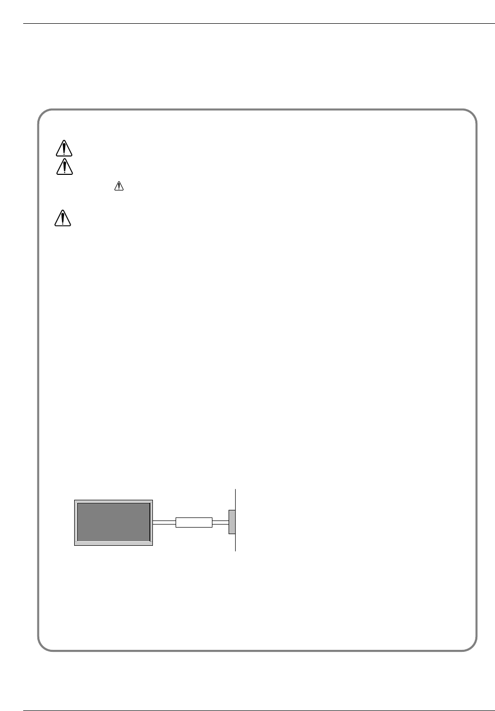
*Safety instructions have two kinds of information, and each meaning of it is as below.
Take care of danger that may happen under specific condition.
The violation of this instruction may cause serious injuries and even death.
The violation of this instruction may cause light injuries or damage of the
product.
WARNING
NOTES
Power
supplier
Short-circuit
breaker
Owner’s Manual 3
Safety Instructions
1. Never touch the power plug with a wet hand.
This may cause an electric shock.
2. Disconnect from the mains and remove all con-
nections before moving.
3. Do not place the product in a built-in installation
such as a bookcase or rack.
Ventilation required.
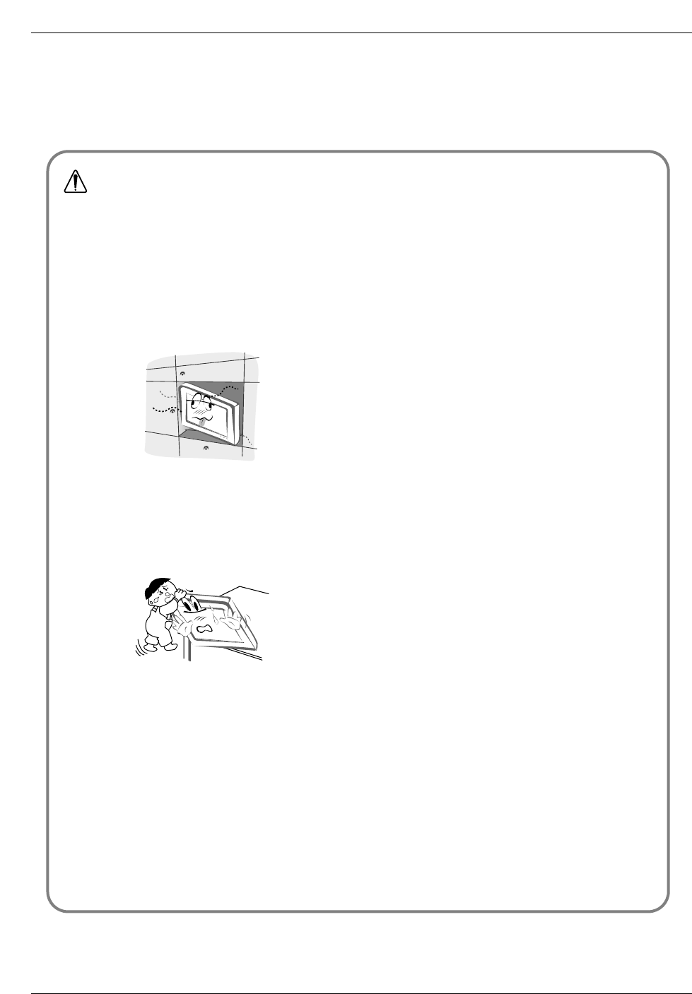
4. When installing the product on a table, be careful
not to place the edge of its stand.
This may cause the product to fall, causing serious injury to a
child or adult, and serious damage to the product.
5. Do not place an outside antenna in the vicinity of
overhead power lines or other electric light or
power circuits.
This may cause an electric shock.
6. There should be enough distance between an out-
side antenna and power lines to keep the former
from touching the latter even when the antenna
falls.
This may cause an electric shock.
7. Do not pull the cord but the plug when unplug-
ging.
This may cause a fire.
8. Ensure the power cord doesn’t trail across any
hot objects like a heater.
This may cause a fire or an electric shock.
9. Do not plug when the power cord or the plug is
damaged or the connecting part of the power out-
let is loose.
This may cause a fire or an electric shock.
10. Dispose of used batteries carefully to protect a
child from eating them.
In case that it eats them, take it to see a doctor immediately.
11. When moving the product assembled with speak-
ers do not carry holding the speakers.
This may cause the product to fall, causing serious injury to a
child or adult, and serious damage to the product.
12. Unplug this product from the wall outlet before
cleaning. Do not use liquid cleaners or aerosol
cleaners.
This may cause damaged the product or could give an elec-
tric shock.
13. Contact the service center once a year to clean
the internal part of the product.
Accumulated dust can cause mechanical failure.
14. The distance between eyes and the screen should
be about 5 ~ 7 times as long as diagonal length of
the screen.
If not, eyes will strain.
15. Unplug the product from the wall outlet when it is
left unattended and unused for long periods of
time.
Accumulated dust may cause a fire or an electric shock from
deterioration or electric leakage.
16. Only use the specified batteries.
This make cause damaged the product or could give an elec-
tric shock.
NOTE

4 Plasma TV
Safety Instructions
Contents
Contents
After reading this manual, keep it handy for future reference.
Safety Instructions . . . . . . . . . . . . . . . . . . . . . . . . . . . . .2~3
Introduction
Controls . . . . . . . . . . . . . . . . . . . . . . . . . . . . . . .6
Connection Options . . . . . . . . . . . . . . . . . . . . . .7
Remote Control Key Functions . . . . . . . . . . . . . .8
Installation
Installation Instruction . . . . . . . . . . . . . . . . . . . . . . .9
External Equipment Connections . . . . . . . . . .10~14
Antenna Connection . . . . . . . . . . . . . . . . . . . . .10
VCR Setup / Cable TV Setup . . . . . . . . . . . . . .11
External A/V Source Setup . . . . . . . . . . . . . . . .12
DVD Setup . . . . . . . . . . . . . . . . . . . . . . . . . . . .12
DTV Setup / Monitor Out Setup . . . . . . . . . . . . .13
PC Setup . . . . . . . . . . . . . . . . . . . . . . . . . . . . .14
Operation
Turning the TV On . . . . . . . . . . . . . . . . . . . . . . . .15
On-screen Menus Language Selection . . . . . . . . .15
Channel Menu Options
Auto Program: Channel Search . . . . . . . . . . . . .16
Manual Program: Adding/Deleting Channels . . .16
Fine Tuning Adjustment . . . . . . . . . . . . . . . . . .16
Signal Reception Booster . . . . . . . . . . . . . . . . .17
Favorite Channel Memory . . . . . . . . . . . . . . . . .17
Picture Menu Options
APC (Auto Picture Control) . . . . . . . . . . . . . . . .18
XD . . . . . . . . . . . . . . . . . . . . . . . . . . . . . . . . . .18
Color Temperature Control . . . . . . . . . . . . . . . .18
Fleshtone . . . . . . . . . . . . . . . . . . . . . . . . . . . . .19
sRGB . . . . . . . . . . . . . . . . . . . . . . . . . . . . . . . .19
Manual Picture Control(User option) . . . . . . . . .19
Sound Menu Options
DASP (Digital Auto Sound Processing) . . . . . . .20
BBE . . . . . . . . . . . . . . . . . . . . . . . . . . . . . . . . .20
AVL (Auto Volume Leveler) . . . . . . . . . . . . . . . .20
Manual Sound Control (User option) . . . . . . . . .21
Stereo/SAP Broadcasts Setup . . . . . . . . . . . . .21
Timer Menu Options
Clock Setup . . . . . . . . . . . . . . . . . . . . . . . . . . .22
On/Off Timer Setup . . . . . . . . . . . . . . . . . . . . .22
Auto Off / Sleep Timer . . . . . . . . . . . . . . . . . . .23
Special Menu Features
Key Lock . . . . . . . . . . . . . . . . . . . . . . . . . . . . .23
ISM (Image Sticking Minimization) Method . . . .23
Low Power . . . . . . . . . . . . . . . . . . . . . . . . . . . .24
XD Demo . . . . . . . . . . . . . . . . . . . . . . . . . . . . .24
Closed Captions . . . . . . . . . . . . . . . . . . . . . . . .25
Captions . . . . . . . . . . . . . . . . . . . . . . . . . . . . . .25
Caption/Text . . . . . . . . . . . . . . . . . . . . . . . . . . .25
Screen Menu Features
Auto Adjustment . . . . . . . . . . . . . . . . . . . . . . .26
Setting Picture Format . . . . . . . . . . . . . . . . . . .26
Screen Position . . . . . . . . . . . . . . . . . . . . . . . .26
Manual Configure . . . . . . . . . . . . . . . . . . . . . .27
Screen VGA Mode . . . . . . . . . . . . . . . . . . . . . .27
Screen Adjustments . . . . . . . . . . . . . . . . . . . . .27
Cinema Mode Setup . . . . . . . . . . . . . . . . . . . . .27
Luminance Noise Reduction . . . . . . . . . . . . . . .28
Initializing (Reset to original factory value) . . . . .28
Split Zoom . . . . . . . . . . . . . . . . . . . . . . . . . . . .28
PIP (Picture-In-Picture)/Double Window Feature
Watching PIP/Double Window . . . . . . . . . . . . ..29
Swapping the PIP/Double Window . . . . . . . . . .29
TV Program selection for PIP . . . . . . . . . . . . . .29
Selecting an Input Signal Source for PIP/Double Window .
29
Moving the PIP sub picture . . . . . . . . . . . . . . . .29
PIP Size . . . . . . . . . . . . . . . . . . . . . . . . . . . . . .29
PIP Transparency (PIP Mode only) . . . . . . . . . .29
External Control Device Setup . . . . . . . . . . . . . . . .30~35
IR Codes . . . . . . . . . . . . . . . . . . . . . . . . . . . . . . . .36~37
Troubleshooting Checklist . . . . . . . . . . . . . . . . . . . . . .38
Product Specifications . . . . . . . . . . . . . . . . . . . . . . . . .39

Owner’s Manual 5
Introduction
Introduction
Introduction
What is a Plasma Display Panel (PDP)?
A plasma display panel is the latest display technology and the best way to achieve flat panel displays with excellent image quality
and large screen sizes that are easily viewable. The PDP can be thought of as a descendant of the neon lamp and it can be also
be viewed as a series of fluorescent lamps.
How does it work?
PDP is an array of cells, known as pixels, which are comprised of 3 sub pixels, corresponding to the colors red, green, and blue.
Gas in a plasma state is used to react with phosphors in each sub-pixel to produce colored light (red, green, or blue). These phos-
phors are the same types used in Cathode Ray Tube (CRT) devices such as televisions and common computer monitors.
You get the rich, dynamic colors that you expect. Each sub-pixel is individually controlled by advanced electronics to produce over
16 million different colors. All of this means that you get perfect images that are easily viewable in a display that is less than 5
inches thick.
160° - Wide angle range of vision
Your flat panel plasma screen offers an exceptionally broad viewing angle -- over 160 degrees. This means that the display is
clear and visible to viewers anywhere in the room who can see the screen.
Wide Screen
The screen of the Plasma Display is so wide that your viewing experience is as if you are in a theater.
Multimedia
Connect your plasma display to a PC and you can use it for conferencing, games, and Internet browsing. The Picture-in-Picture
feature allows you to view your PC and video images simultaneously.
Versatile
The light weight and thin size makes it easy to install your plasma display in a variety of locations where conventional TVs will not
fit.
The PDP Manufacturing Process: a few minute colored dots may be present on the PDP screen
The PDP (Plasma Display Panel), which is the display device of this product is composed of 0.9 to 2.2 million cells. A few cell
defects will normally occur in the PDP manufacturing process. Several tiny, minute colored dots visible on the screen should be
acceptable. This also occurs in other PDP manufacturers' products. The tiny dots appearing does not mean that this PDP is defec-
tive. Thus a few cell defects are not sufficient cause for the PDP to be exchanged or returned. Our production technology mini-
mizes these cell defects during the manufacture and operation of this product.
Cooling Fan Noise
In the same way that a fan is used in a PC computer to keep the CPU (Central Processing Unit) cool, the PDP is equipped with
cooling fans to cool the Monitor and improve its reliability. Therefore, a certain level of noise could occur while the fans are operat-
ing and cooling the PDP.
The fan noise doesn't have any negative effect on the PDP's efficiency or reliability. The noise from these fans is normal during the
operation of this product. We hope you understand that a certain level of noise from the cooling fans is acceptable and is not suffi-
cient cause for the PDP to be exchanged or returned.
6 Plasma TV
Introduction
Controls
Controls
ON/OFF
TV/VIDEO
MENU
VOL CH
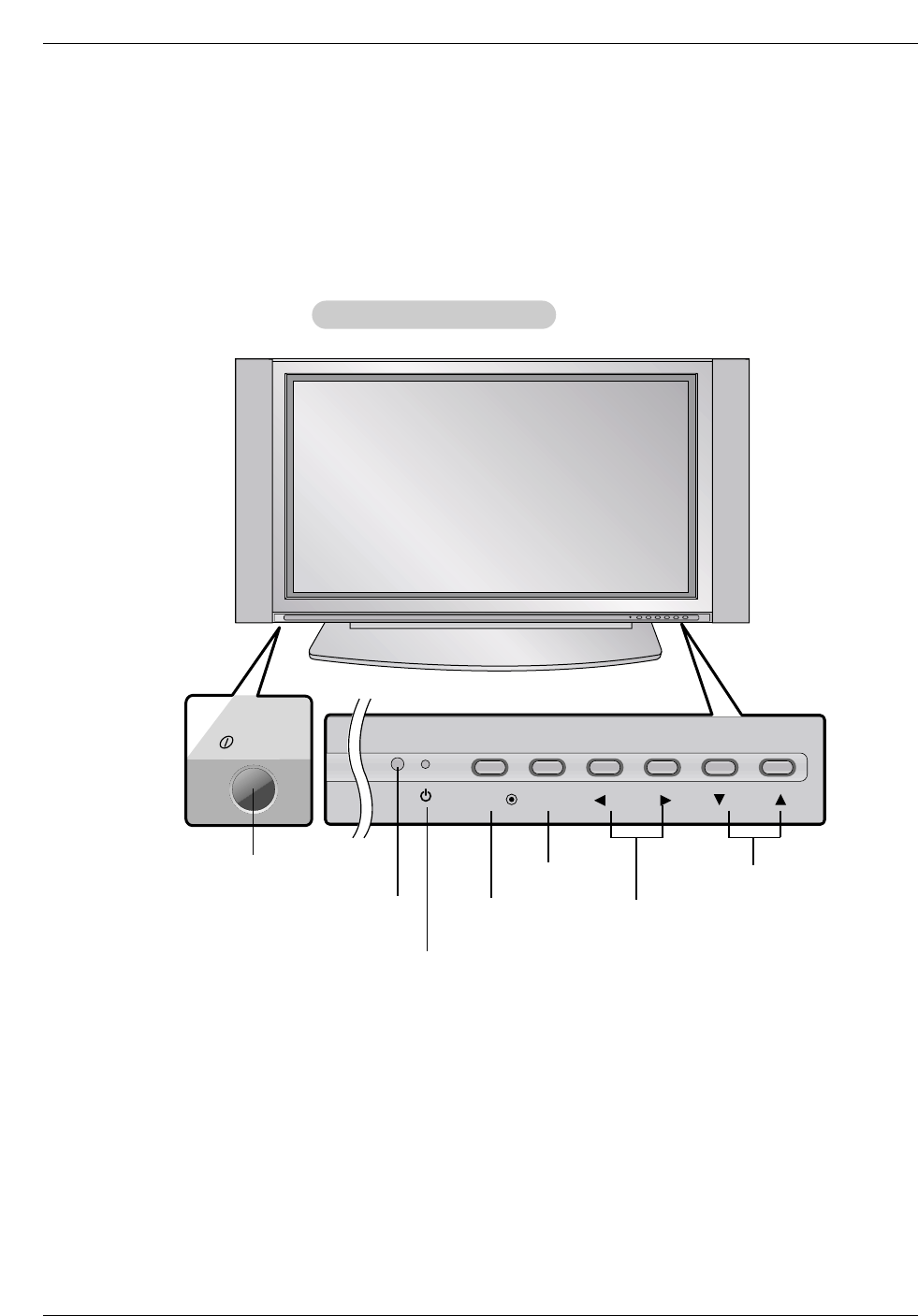
ON/OFF Button
- This is a simplified representation of front panel.
Here shown may be somewhat different from your TV.
- This manual explains the features available on the RP-42PX10 TVs.
Front Panel Controls
Front Panel Controls
Remote Control Sensor VOLUME (F,G) Buttons
Power Standby Indicator
Illuminates red in standby mode,
Illuminates green when the TV is
turned on.
CHANNEL (E, D) Buttons
MENU Button
TV/VIDEO Button
Owner’s Manual 7
Introduction
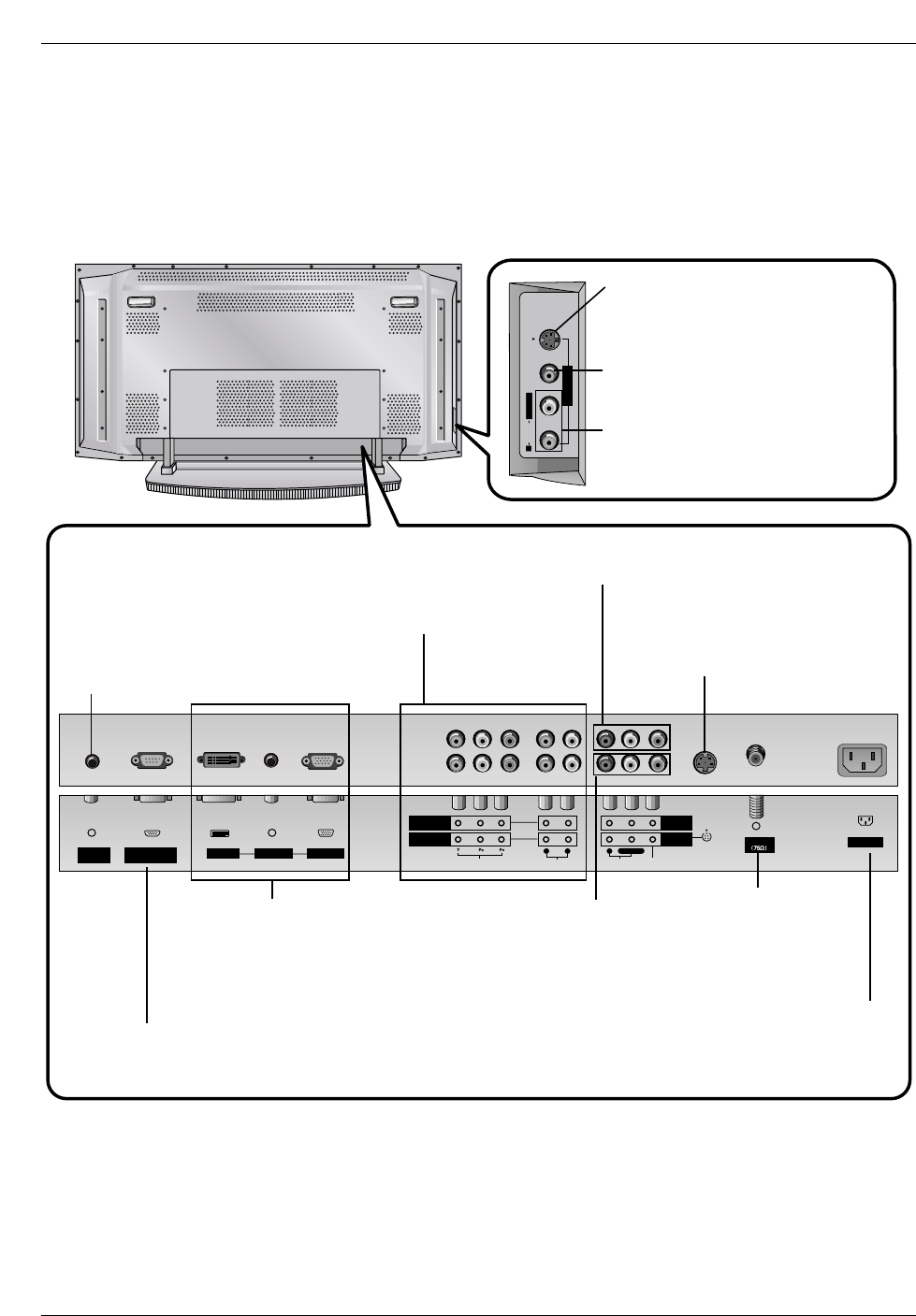
Connection Options
Connection Options
RGB INPUT
Antenna
AUDIO INPUT
DVI INPUT
S-VIDEO
REMOTE
CONTROL
AC INPUT
AUDIOVIDEO
COMPONENT
INPUT 2
COMPONENT
INPUT 1
MONITOR
OUTPUT
A/V
INPUT 1
RL
AUDIO VIDEO
R
RS-232C INPUT
(CONTROL/SERVICE)
L/MONO
RS-VIDEO VIDEO
L / MONO
AUDIO
A/V INPUT2
Antenna Input
Connect cable or antenna
signals to the TV, either
directly or through your
cable box.
RGB Input/Audio Input/DVI Input
Connect the monitor output connector from a
PC to the appropriate input port. If you want to
use RGB/DVI audio, we strongly recommend
that you use the cable that has a core, or the
EMI filter core along with separate cable.
Audio/Video Input 1
Connect audio/video
output from an external
device to these jacks.
DVD/DTV Input (Component 1-2)
Connect a component video/audio
device to these jacks.
Monitor Output
Connect a second TV or Monitor.
Remote Control Port
Connect your wired
remote control here.
S-Video Input
Connect S-Video out from an S-VIDEO
device to the S-VIDEO input.
Power Cord Socket
This TV operates on AC power. The voltage is indicated
on the Specifications page. Never attempt to operate
the TV on DC power.
RS-232C INPUT (CONTROL/SERVICE) PORT
Connect to the RS-232C port on a PC.
S-VIDEO Input
A connection available to provide better
picture quality than the video input.
VIDEO Input
Connects the video signal from a video
device.
AUDIO Input
Use to connect to hear stereo sound
from an external device.
8 Plasma TV
Introduction
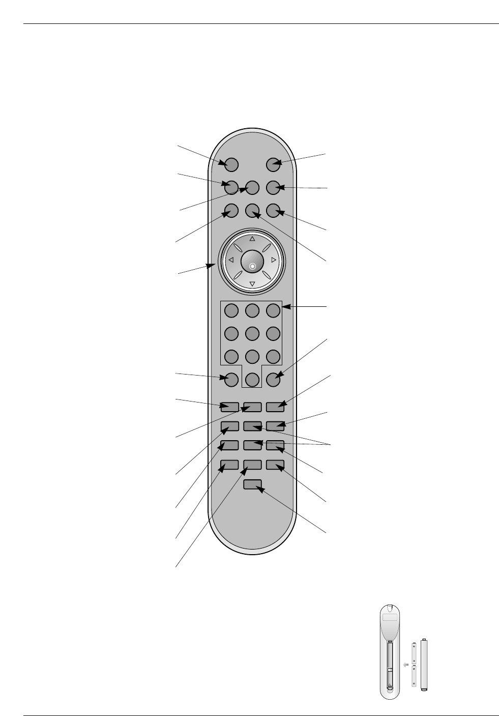
- When using the remote control, aim it at the remote control sensor on the TV.
POWERMUTE
TV/VIDEO
MULTIMEDIA
MTS
CAPTION
CH
CH
VOL
ENTER
123
456
789
0
VOL
ARC
MENU
FCR
PIP/DW
APC DASP
REVIEW
SPLIT ZOOM
PIP CH +
SLEEP
PIP CH -
PIP INPUTWIN.SIZE
SWAP
MEMORY/ERASE
A.PROGPOSITION
MUTE
Switches the sound on or off.
TVVIDEO
Selects: TV, Video 1-2, Component
1-2, RGB, and DVI input sources.
MULTIMEDIA
Selects: Component 1-2, RGB, and
DVI input sources.
CAPTION
Selects CAPTION mode.
VOLUME UP/DOWN
Increases/decreases the sound level.
Selects a menu item.
Switches the set on from standby
CHANNEL UP/DOWN
Selects available channels found with
Auto program. Adjusts menu settings.
ENTER
Accepts your selection or displays the
current mode.
POWER
Turns your TV on or off.
MTS
Selects the MTS sound: Mono, Stereo,
or SAP.
MENU
Brings up the main menu to the screen.
REVIEW
Tunes to the last channel viewed.
NUMBER buttons
ARC
Changes the picture format.
PIP INPUT
Selects the input source for the sub picture.
SWAP
Exchanges the main/sub images.
PIP/DW
Switches between PIP and Double
Window modes. PIPCH-/PIPCH+
Changes to next lower/higher PIP channel.
POSITION
Moves the sub picture in pip mode.
SLEEP
Sets the sleep timer.
FCR
Use to scroll the favorite channel list.
MEMORY/ERASE
Memorizes or erases selected channel.
A.PROG (AUTO PROGRAM)
Searches for available channels.
SPLIT ZOOM
Enlarges the picture with regular ration.
Installing Batteries
• Open the battery compartment cover on the back side and install the batteries
matching correct polarity (+ with +, - with -).
• Install two 1.5V AAA batteries. Don’t mix old or used batteries with new ones.
Replace cover.
Remote Control Key Functions
Remote Control Key Functions
WIN. SIZE
Adjusts the sub picture size.
APC
Adjusts the factory preset picture according
to the room.
DASP
Selects the sound appropriate for the pro-
gram's character.
Owner’s Manual 9
Introduction
Installation
Installation
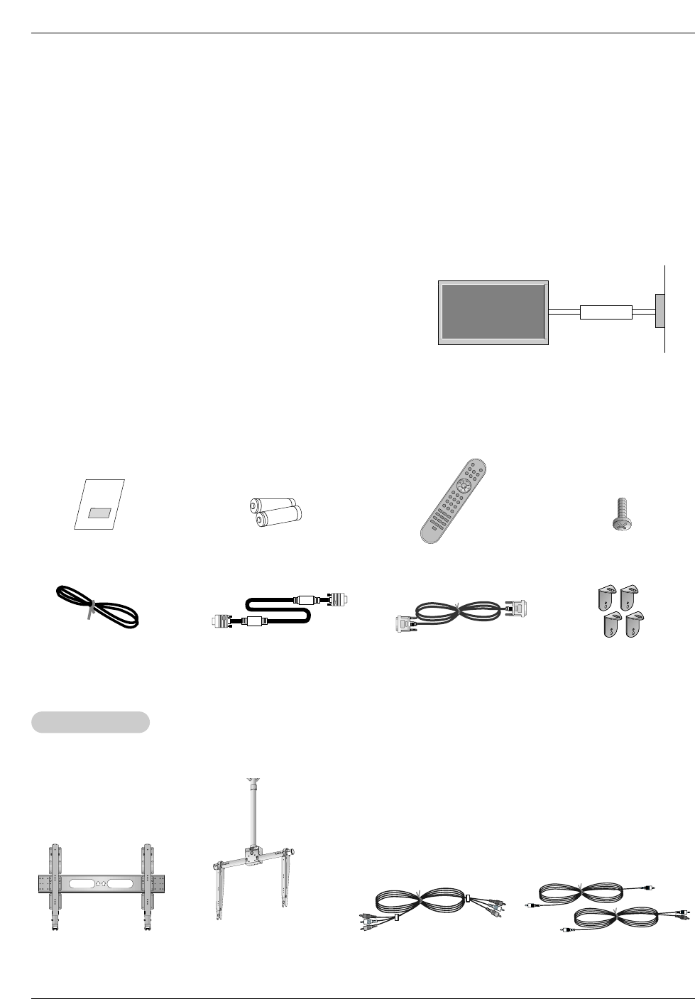
Ensure that the following accessories are included with your plasma display. If an accessory is missing, please contact the dealer
where you purchased the product.
• The TV can be installed in various ways such as on a wall, or on a desktop etc.
• The TV is designed to be mounted horizontally. The speakers shown are optional.
• It is recommended that RP-42PX10 model only be used at an altitude of less than 3281 feet (1000m) to get the best quality picture
and sound.
• It is recommended that RP-42PX10H model only be used at an altitude of less than 6561 feet (2000m) to get the best quality pic-
ture and sound.
GROUNDING
Ensure that you connect the grounding / earth wire to prevent possible
electric shock. If grounding methods are not possible, have a qualified
electrician install a separate circuit breaker. Do not try to ground the
unit by connecting it to telephone wires, lightening rods, or gas pipes.
Power
Supply
Short-circuit
Breaker
Installation Instructions
Installation Instructions
40
42
50
42
40
Ceiling mounting bracket
- Optional extras can be changed or modified for quality improvement without any notification new optional extras can be added.
- Contract your dealer for buying these items.
Option Extras
Option Extras
Tilt wall mounting bracket
404250 40 42 50
Video cables Audio cables
Owner’s Manual
1.5V
1.5V
Batteries
Power Cord
POWER
MUTE
TV/VIDEO
MULTIMEDIA
MTS
CAPTION
CH
CH
VOL
ENTER
123
456
789
0
VOL
ARC
MENU
FCR
PIP/DW
APC DASP
REVIEW
SPLIT ZOOM
PIP CH +
SLEEP
PIP CH -
PIP INPUT
WIN.SIZE
SWAP
MEMORY/ERASE
A.PROG
POSITION
Remote Control
D-sub 15 pin cable DVI Cable 2-TV brackets
2-Wall brackets
2-TV bracket bolts
10 Plasma TV
Installation
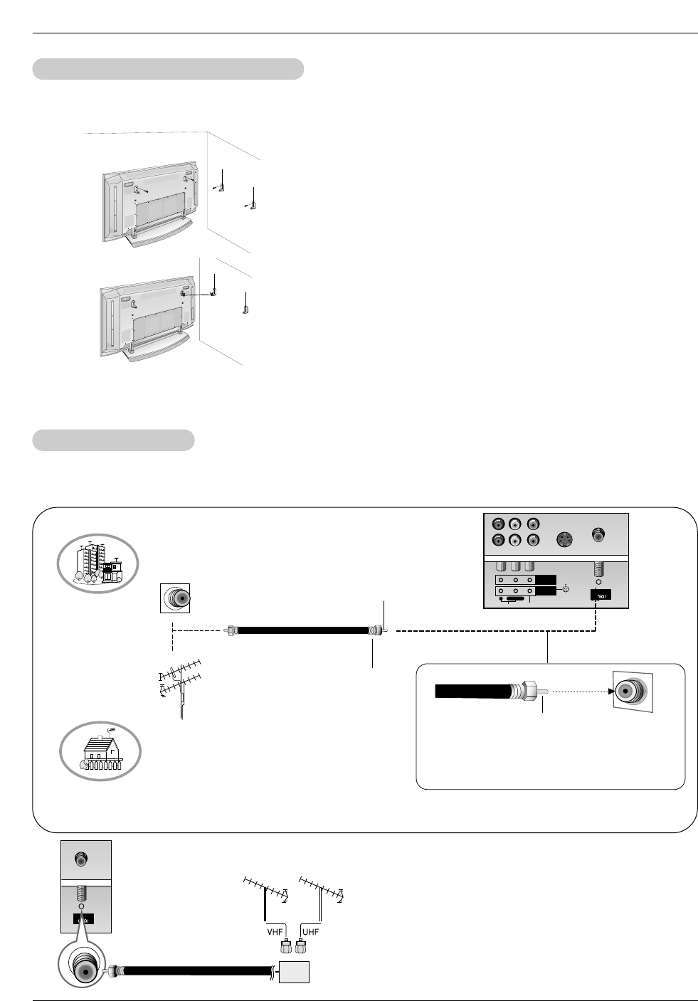
- Antenna or Cable Service without a Cable Box Connections
- For optimum picture quality, adjust antenna direction if needed.
External Equipment Connections
External Equipment Connections
Antenna Connection
Antenna Connection
•In a poor signal area to improve picture quality, purchase
and install a signal amplifier.
•If the antenna needs to be split for two TV’s, install a “2-Way
Signal Splitter” in the connections.
•If the antenna is not installed properly, contact your dealer
for assistance.
Antenna
Signal
Amplifier
Antenna
S-VIDEO
MONITOR
OUTPUT
A/V
INPUT 1
AUDIO VIDEO
RL/MONO
Multi-family Dwellings/Apartments
(Connect to wall antenna socket)
Single-family Dwellings /Houses
(Connect to wall jack for outdoor antenna)
outdoor
antenna
wall antenna
socket
VHF antenna
UHF antenna
RF coaxial wire (75 ohm)
Bronze Wire
Turn clockwise to tighten.
Bronze Wire
Be careful not to bend the bronze wire when
connecting the antenna.
- Secure the TV assembly by attaching it to a wall for additional support.
Attaching the
Attaching the TV assembly to the wall
TV assembly to the wall
• Install the TV brackets on the TV as shown.
Insert the 2 bolts and tighten securely, in the upper holes
on the bracket.
Install the wall brackets on the wall with 4 bolts*, (not
supplied with the product), as shown.
Match the height of the TV brackets and the wall brack-
ets.
Check to be sure the brackets are tightened securely.
• Secure the TV assembly to the wall with strong strings
or wound wire cables, (not supplied with the product), as
shown.
Owner’s Manual 11
Installation
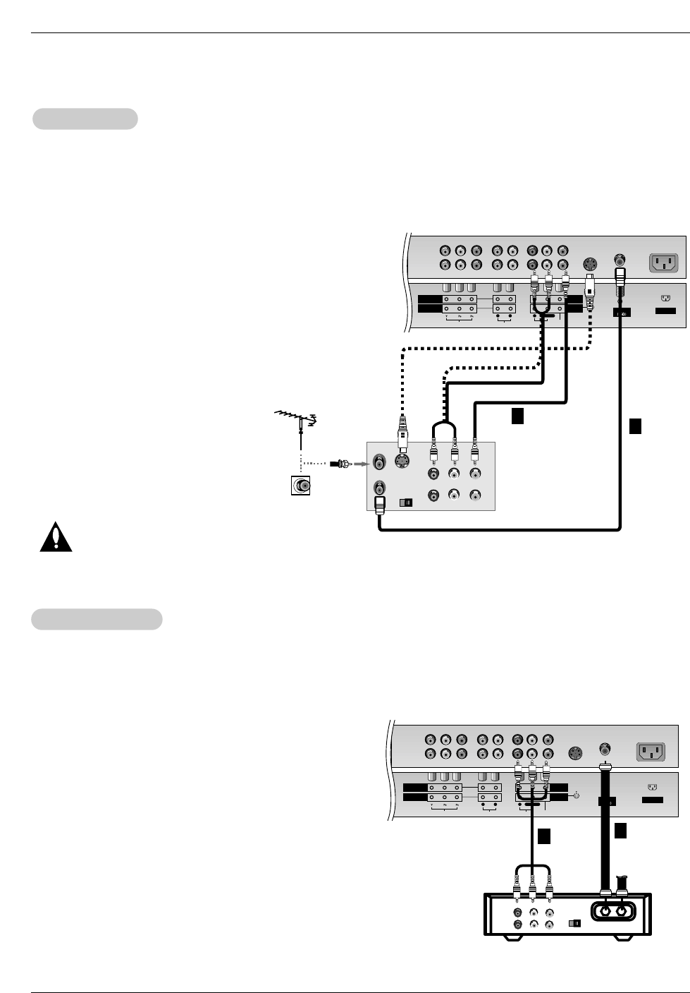
NOTE: All cables shown are not included with the TV
- To avoid picture noise (interference), leave an adequate distance between the VCR and TV
- Use the ISM Method (on the Option menu) feature to avoid having a fixed image remain on the screen for a long period of time.
Typically a frozen still picture from a VCR. If the 4:3 picture format is used; the fixed images on the sides of the screen may
remain visible on the screen.
Connection Option 1
Set VCR output switch to 3 or 4 and then tune
TV to the same channel number.
Connection Option 2
1. Connect the audio and video cables from the
VCR's output jacks to the TV input jacks, as
shown in the figure.
When connecting the TV to VCR, match the
jack colors (Video = yellow, Audio Left = white,
and Audio Right = red).
If you connect an S-VIDEO output from VCR to
the S-VIDEO input, the picture quality is
improved; compared to connecting a regular
VCR to the Video input.
2. Insert a video tape into the VCR and press
PLAY on the VCR. (Refer to the VCR owner’s
manual.)
3. Select the input source with using the
TV/VIDEO button on the remote control. (If
connected to A/V INPUT 1, select Video 1
input source)
Do not connect to both Video and S-
Video at the same time. In the event
that you connect both Video and the
S-Video cables, only the S-Video will
work.)
VCR Setup
VCR Setup
Antenna
S-VIDEO AC INPUT
AUDIOVIDEO
COMPONENT
INPUT 2
COMPONENT
INPUT 1
MONITOR
OUTPUT
A/V
INPUT 1
RL
AUDIO VIDEO
RL/MONO
S-VIDEO OUT
IN
(R) AUDIO (L) VIDEO
34
OUTPUT
SWITCH
ANT OUT
ANT IN
- After subscribing to a cable TV service from a local provider and installing a converter, you can watch cable TV programming.
The TV cannot display TV programming unless a TV tuner device or cable TV converter box is connected to the TV.
- For further information regarding cable TV service, contact your local cable TV service provider(s).
Connection Option 1
1. Select 3 or 4 with channel switch on cable box.
2. Tune the TV channel to the same selected output channel on
cable box.
3. Select channels at the cable box or with the cable box remote
control.
Connection Option 2
1. Connect the audio and video cables from the Cable Box's output
jacks to the TV input jacks, as shown in the figure.
When connecting the TV to a Cable Box, match the jack colors
(Video = yellow, Audio Left = white, and Audio Right = red).
2. Select the input source with using the TV/VIDEO button on the
remote control. (If connected to A/V INPUT 1, select Video 1
input source)
3. Select your desired channel with the remote control for cable
box.
Cable
Cable TV Setup
TV Setup
Antenna
S-VIDEO AC INPUT
AUDIOVIDEO
COMPONENT
INPUT 2
COMPONENT
INPUT 1
MONITOR
OUTPUT
A/V
INPUT 1
RL
AUDIO VIDEO
RL/MONO
TV
VCR RF Cable
(R) AUDIO (L) VIDEO
34
OUTPUT
SWITCH
VCR
Cable Box
1
2
1
2
12 Plasma TV
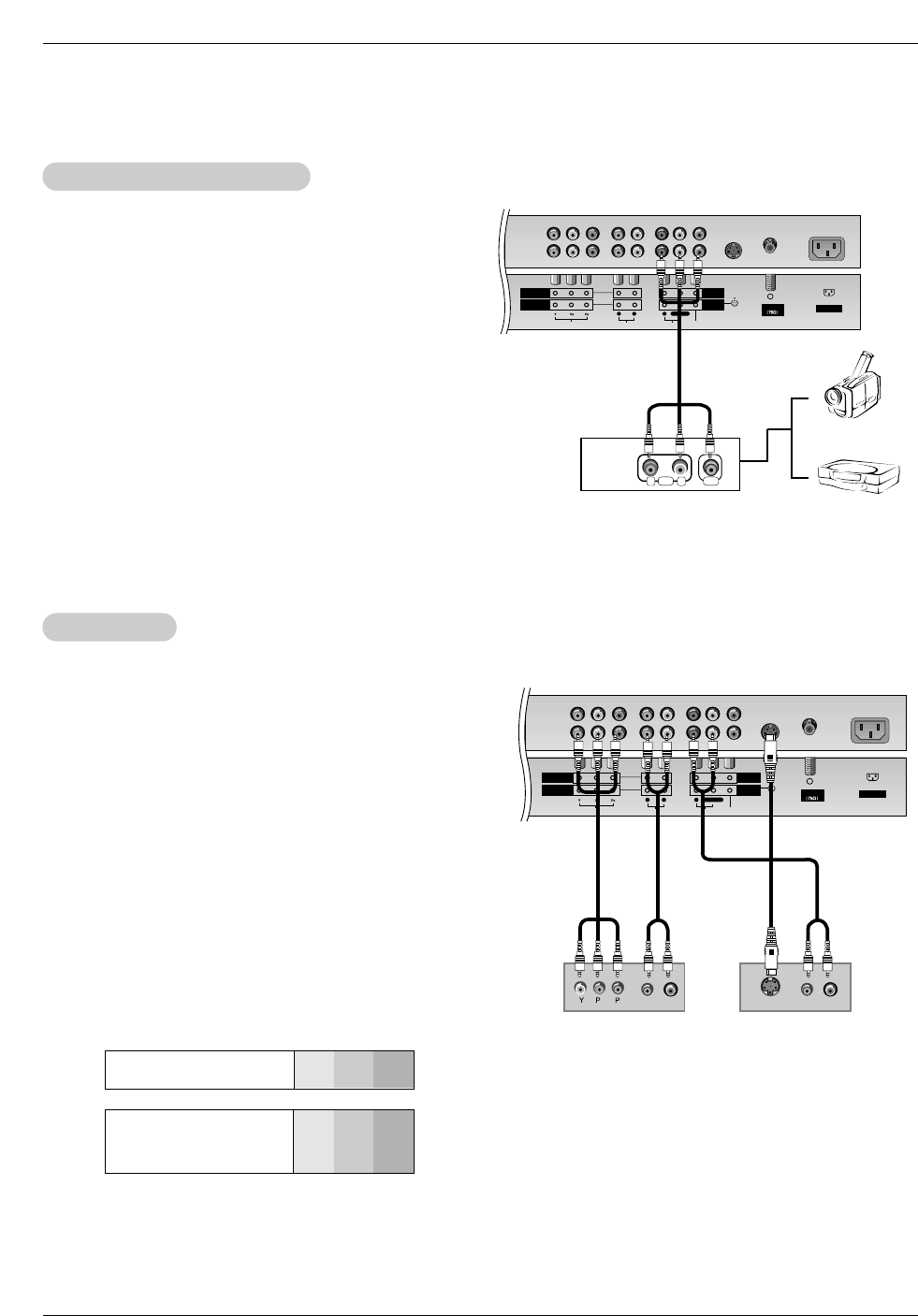
Installation
•Component Input ports
To get better picture quality, connect a DVD player to the compo-
nent input ports as shown below.
How to connect
Connect the audio and video cables from the external
equipment's output jacks to the TV input jacks, as shown in
the figure.
When connecting the TV to external equipment, match the
jack colors (Video = yellow, Audio Left = white, and Audio
Right = red).
How to use
1. Select the input source with using the TV/VIDEO button on
the remote control. (If connected to A/V INPUT 1, select
Video 1 input source).
2. Operate the corresponding external equipment. Refer to
external equipment operating guide.
Component ports
on the TV YPBPR
Video output ports
on DVD player
Y
Y
Y
Y
Pb
B-Y
Cb
PB
Pr
R-Y
Cr
PR
How to connect
1. Connect the DVD video outputs (Y, PB, PR) to the COMPONENT
(Y, PB, PR) INPUT jacks on the TV and connect the DVD audio
outputs to the AUDIO INPUT jacks on the TV, as shown in the fig-
ure.
2. If your DVD only has an S-Video output jack, connect this to the
S-VIDEO input on the TV and connect the DVD audio outputs to
the AUDIO INPUT jacks on the TV, as shown in the figure.
NOTE: If your DVD player does not have component video output,
use S-Video.
How to use
1. Turn on the DVD player, insert a DVD.
2. Use the TV/VIDEO or MULTIMEDIA button on the remote control
to select Component 1 or Component 2. (If connected to S-
VIDEO, select the Video 1 or Video 2 external input source.)
3. Refer to the DVD player's manual for operating instructions.
External
External A/V Source Setup
A/V Source Setup
DVD Setup
DVD Setup
Antenna
S-VIDEO AC INPUT
AUDIOVIDEO
COMPONENT
INPUT 2
COMPONENT
INPUT 1
MONITOR
OUTPUT
A/V
INPUT 1
RL
AUDIO VIDEO
RL/MONO
RL
AUDIO VIDEO
Antenna
S-VIDEO AC INPUT
AUDIOVIDEO
COMPONENT
INPUT 2
COMPONENT
INPUT 1
MONITOR
OUTPUT
A/V
INPUT 1
RL
AUDIO VIDEO
RL/MONO
BR
(R) AUDIO (L) (R) AUDIO (L)
S-VIDEO
DVD
or
Camcorder
Video Game Set
Owner’s Manual 13
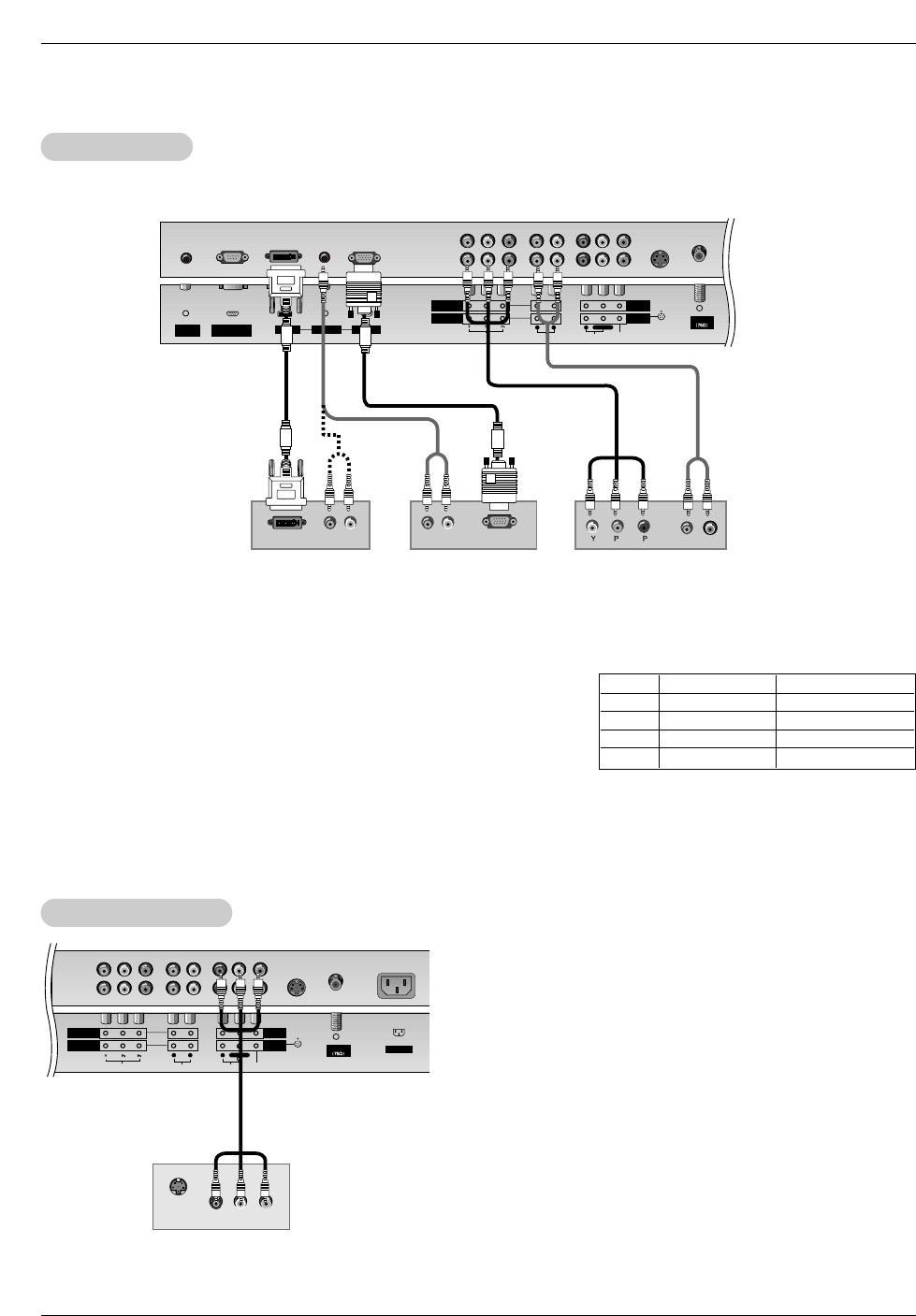
Installation
How to connect
Use the TV’s COMPONENT (Y, PB, PR) INPUT, RGB or DVI jack for video
connections, depending on your set-top box connector. Then, make the
corresponding audio connections.
How to use
1. Turn on the digital set-top box. (Refer to the owner’s manual for the digital
set-top box.)
2. Use TV/VIDEO or MULTIMEDIA on the remote control to select
Component 1, Component 2, RGB, or DVI source.
- To watch digitally broadcast programs, purchase and connect a digital set-top box.
DTV Setup
DTV Setup
RGB INPUT
Antenna
AUDIO INPUT
DVI INPUT
S-VIDEO
REMOTE
CONTROL AUDIOVIDEO
COMPONENT
INPUT 2
COMPONENT
INPUT 1
MONITOR
OUTPUT
A/V
INPUT 1
RL
AUDIO VIDEO
R
RS-232C INPUT
(CONTROL/SERVICE)
L/MONO
BR
(R) AUDIO (L)
(R) AUDIO (L)
RGB-DTV OUTPUT
(R) AUDIO (L)
DVI-DTV OUTPUT
Digital Set-top Box
or
or
Signal
480i
480p
720p
1080i
Component 1/2
Yes
Yes
Yes
Yes
RGB,DVI
No
Yes
Yes
Yes
The TV has a special signal output capability which allows you to
hook up a second TV or monitor.
Connect the second TV or monitor to the TV’s MONITOR OUTPUT.
See the Operating Manual of the second TV or monitor for further
details regarding that device’s input settings.
NOTE
• Component, RGB-PC/RGB-DTV, DVI-PC/DVI-DTV input sources
cannot be used for Monitor out.
Antenna
S-VIDEO AC INPUT
AUDIOVIDEO
COMPONENT
INPUT 2
COMPONENT
INPUT 1
MONITOR
OUTPUT
A/V
INPUT 1
RL
AUDIO VIDEO
RL/MONO
S-VIDEO IN
(R) AUDIO (L) VIDEO
Monitor Out Setup
Monitor Out Setup
14 Plasma TV
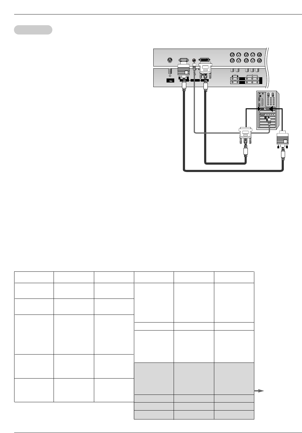
Installation
How to connect
1. To get the best picture quality, adjust the PC
graphics card to 640x 480, 60Hz.
2. Use the TV’s RGB INPUT or DVI (Digital Visual
Interface) INPUT port for video connections,
depending on your PC connector.
• If the graphic card on the PC does not output
analog and digital RGB simultaneously, connect
only one of either RGB INPUT or DVI INPUT to
display the PC on the TV.
• If the graphic card on the PC does output analog
and digital RGB simultaneously, set the TV to
either RGB or DVI; (the other mode is set to Plug
and Play automatically by the TV.)
3. Then, make the corresponding audio connection. If
using a sound card, adjust the PC sound as
required.
PC Setup
PC Setup
RGB INPUT
Antenna
AUDIO INPUT
DVI INPUT
AUDIO INPUT VIDEO INPUT
COMPONENT 2 DVD
/DTV
INPUT
COMPONENT 1
RL
35.156
37.879
48.077
46.875
53.674
49.725
48.363
56.476
60.023
68.677
54.348
63.995
67.500
77.487
68.681
60.023
63.981
Resolution
640x350
720x400
640x480
848x480
Horizontal
Frequency(KHz) Vertical
Frequency(Hz)
852x480
31.468
37.861
31.469
37.927
31.469
35.000
37.861
37.500
43.269
31.500
37.799
39.375
31.500
37.799
39.375
70.09
85.08
70.08
85.03
59.94
66.66
72.80
75.00
85.00
60.00
70.00
75.00
60.00
70.00
75.00
Resolution
800x600
Horizontal
Frequency(KHz) Vertical
Frequency(Hz)
832x624
1024x768
1152x864
1152x870
1280x1024
56.25
60.31
72.18
75.00
85.06
74.55
60.00
70.06
75.02
85.00
60.05
70.01
75.00
85.00
75.06
60.02
60.02
1280x960
How to use
1. Turn on the PC and the TV.
2. Turn on the display by pressing the POWER button on the TV's remote control.
3. Use TV/VIDEO or MULTIMEDIA on the remote control to select RGB, or DVI source.
4. Check the image on your TV. There may be noise associated with the resolution, vertical pattern, contrast or brightness in PC
mode. If noise is present, change the PC mode to another resolution, change the refresh rate to another rate or adjust the
brightness and contrast on the menu until the picture is clear. If the refresh rate of the PC graphic card can not be changed,
change the PC graphic card or consult the manufacturer of the PC graphic card.
NOTES: • Use a DVI cable.
• Avoid keeping a fixed image on the TV's screen for a long period of time. The fixed image may become permanently
imprinted on the screen. Use the Orbiter screen saver when possible.
• The synchronization input form for Horizontal and Vertical frequencies is separate.
Monitor Display Specifications (RGB / DVI Mode)
RGB Mode Only

Owner’s Manual 15
Operation
-The menus can be shown on the screen in the selected language. First select your language.
1. Press the MENU button and then use D/ Ebutton to select the SPECIAL menu.
2. Press the Gbutton and then use D/ Ebutton to select Language.
3. Press the Gbutton and then use D/ Ebutton to select your desired language.
From this point on, the on-screen menus will be shown in the language of your
choice.
4. Press the ENTER button to save.
Menu Language Selection
Menu Language Selection
T
Turning the TV On
urning the TV On
Turning on the TV just after installation
Turning on the TV (power cord is still connected)
1. Connect power cord correctly.
2. Press the ON/OFF button on the TV. At this moment, the TV is switched to standby mode. Press
the TV/VIDEO, CH (D/ E)button on the TV or press the POWER, TV/VIDEO, MULTIMEDIA,
Number (0 ~ 9) button on the remote control and then the TV will turn on.
•Press the ON/OFF button on the TV to turn the TV on.
1. If the TV was turned off with the ON/OFF button on the TV
2. If the TV was turned off with the remote control and then the ON/OFF button on the TV
•Press the ON/OFF button on the TV and then press the TV/VIDEO, CH (D/ E)button on the TV or
press the POWER, TV/VIDEO, MULTIMEDIA, Number (0 ~ 9) button on the remote control to turn
the TV on.
NOTE
• If you intend to be away on vacation, disconnect the power plug from the wall power outlet.
* In this manual, the OSD (On Screen Display) may be different from your TV’s because it is just an
example to help you with the TV operation.
Operation
Operation
16 Plasma TV
Operation
Channel Menu Options
Channel Menu Options
CHANNEL
PICTURE
SOUND
TIMER
SPECIAL
PIP/DW
TWIN Prev.
MENU
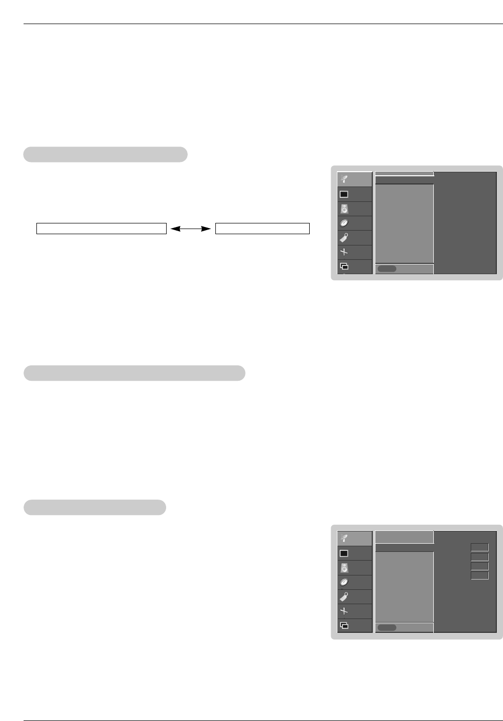
To Start
Auto program G
Manual program
Favorite channel
CHANNEL
PICTURE
SOUND
TIMER
SPECIAL
SCREEN
PIP/DW Prev.
MENU
TV 2
Memory On
Fine 0
Booster Off
Auto program
Manual program G
Favorite channel
- You can add or delete channels from the channel scan manually.
1. Use the D / Eor NUMBER buttons to select the channel number you want to add or delete.
2. Press the MEMORY/ERASE button.
3. Use the MEMORY/ERASE button to select Memory or Erase.
4. Press the ENTER button.
• You can also do Manual program with the CHANNEL menu.
Manual Program:
Manual Program: Adding/Deleting Channels
Adding/Deleting Channels
1. Press the A.PROG button and then press the Gbutton.
AUTO PROGRAM starts the channel search.
If you want to stop auto programming, press the ENTER button. Only the chan-
nels found up to at that time are memorized.
• You can also select the Auto program option and do a channel search in
the CHANNEL menu.
Auto Program: Channel Search
Auto Program: Channel Search
Auto Program should be used to memorize all the active channels in your area before you are able to use the TV.
There are two ways of storing channels in the TV's memory. You can use either.
One is called AUTO PROGRAM and the other is called MANUAL PROGRAM.
In AUTO PROGRAM mode, the TV will memorize the channels in ascending numerical order. If there are additional channels you
want to add or delete, you can manually add or delete those channels with Manual Program.
- Redo Auto Program if the Plasma Display is ever moved to another location.
- Auto Program will search for channels only through the ANT IN jack.
- If channels numbers for broadcast over-the air TV and cable TV are duplicated
where different channels have the same number, press the same number but-
tons again to toggle between:
(For example, press 17 to go to the channel, press 17 again to go to the dupli-
cated channel.)
Broadcast TV Channels Cable TV Channels
- Use this function to correct the picture's instability and condition if it is
poor.
Notes
• To remove fine tuning from a channel, reprogram the finely-tuned channel with
Auto program or Manual Program.
• If a finely-tuned channel is memorized, the color of the channel number changes
to yellow.
1. Press the MENU button and then use D / Ebutton to select the CHANNEL menu.
2. Press the Gbutton and then use D / Ebutton to select Manual program.
3. Press the Gbutton and then use D / Ebutton to select Fine.
4. Use the F / Gbutton to adjust the picture to your preference.
5. Press the ENTER button to save.
Fine
Fine T
Tuning
uning Adjustment
Adjustment
Owner’s Manual 17
Operation
CHANNEL
PICTURE
SOUND
TIMER
SPECIAL
SCREEN
PIP/DW Prev.
MENU
- - - - - - - -
- - - - - - - -
- - - - - - - -
- - - - - - - -
- - - - - - - -
- - - - - - - -
- - - - - - - -
- - - - - - - -
Auto program
Manual program
Favorite channel G
CHANNEL
PICTURE
SOUND
TIMER
SPECIAL
SCREEN
PIP/DW Prev.
MENU
TV 2
Memory On
Fine 0
Booster Off
Auto program
Manual program G
Favorite channel
- Favorite Channels is a convenient feature that lets you quickly scan up to 8 channels of your choice without
having to wait for the TV to scan through all the in-between channels.
1. Press the MENU button and then use D / Ebutton to select the CHANNEL menu.
2. Press the Gbutton and then use D / Ebutton to select Favorite channel.
3. Press the Gbutton and then use D / Ebutton to select the first favorite channel
position.
4. Use the F / Gbutton to set the desired channel number for first favorite channel.
5. Repeat steps 3 to 4 to memorize other favorite channels.
6. Press the ENTER button to save.
• To tune to a favorite channel, press the FCR (Favorite Channel Review) but-
ton repeatedly. The eight favorite channels appear on the screen in numerical
order.
Favorite Channels Setup
Favorite Channels Setup
- If TV signal reception is poor because you are in a fringe area, set Booster to On.
If the picture condition is good, set Booster to Off.
- Adjustments for one channel don’t affect the adjustment for other channels.
Set booster to on or off for each channel separately.
1. Press the MENU button and then use D / Ebutton to select the CHANNEL menu.
2. Press the Gbutton and then use D / Ebutton to select Manual program.
3. Press the Gbutton and then use D / Ebutton to select Booster.
4. Use F / Gbutton to select On or Off.
5. Press the ENTER button to save.
Signal Reception Booster
Signal Reception Booster
18 Plasma TV
Operation
Picture Menu Options
Picture Menu Options
CHANNEL
PICTURE
SOUND
TIMER
SPECIAL
SCREEN
PIP/DW Prev.
MENU
APC
ACC G
Fleshtone
Contrast 100
Brightness 55
Color 55
Sharpness 60
Tint 0
CHANNEL
PICTURE
SOUND
TIMER
SPECIAL
SCREEN
PIP/DW Prev.
MENU
APC
G
ACC
Fleshtone
Contrast 100
Brightness 55
Color 55
Sharpness 60
Tint 0
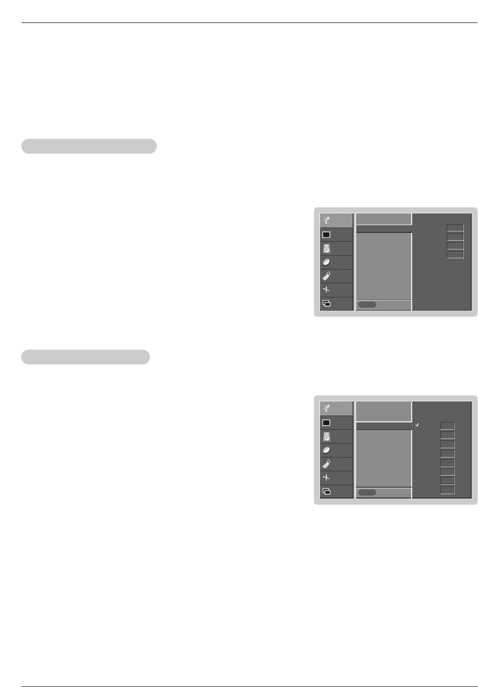
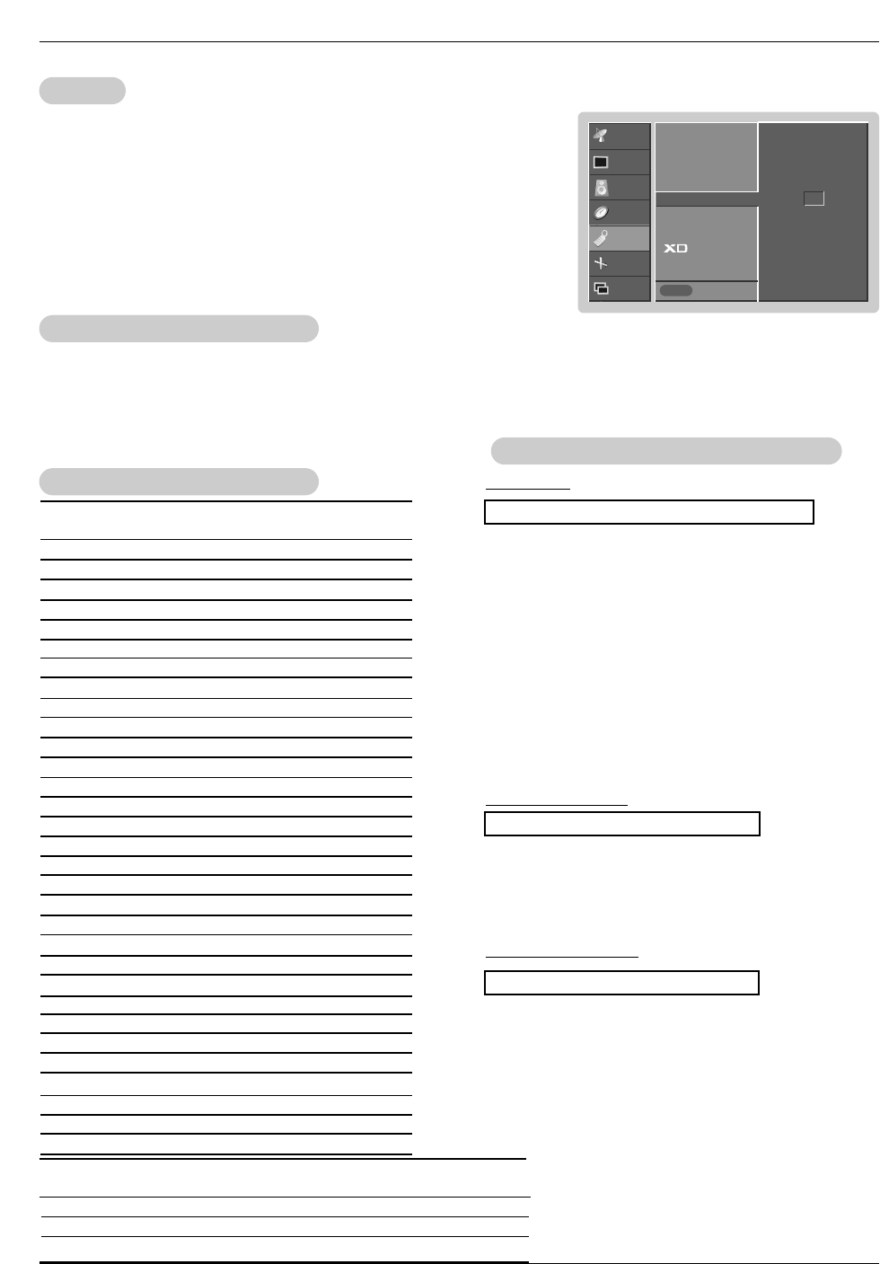
- XD is LG Electronic’s unique picture improving technology to display a real HD
source through an advanced digital signal processing algorithm.
- When selecting APC options (Daylight, Optimum and Night time), XD is auto-
matically change to On.
1. Press the MENU button and then use D / Ebutton to select the PICTURE menu.
2. Press the Gbutton and then use D / Ebutton to select XD.
3. Press the Gbutton and then use D / Ebutton to set On or Off.
4. Press the ENTER button to save.
XD
XD
1. Press the APC button repeatedly to select the picture appearance setup option as shown below.
APC (Auto Picture Control)
APC (Auto Picture Control)
•You can also adjust APC in the PICTURE menu.
•Daylight, Optimum, and Night time settings are preset for good picture quality at the factory and cannot be
changed.
Daylight Optimum Night time Off
- APC adjusts the TV to the best picture appearance.
- If adjusting picture options (contrast, brightness, color, sharpness, or tint) manually, APC automatically
changes to Off.
Auto Color Temperature Control
- To initialize values (reset to default settings), select the Normal option.
1. Press the MENU button and then use D / Ebutton to select the PICTURE menu.
2. Press the Gbutton and then use D / Ebutton to select ACC .
3. Press the Gbutton and then use D / Ebutton to select either: Cool (Preset),
Normal (Default), or Warm (Preset).
4. Press the ENTER button to save.
Color
Color T
Temperature Control
emperature Control
Manual Color Temperature Control (ACC set to Off option)
- You can adjust red, green, or blue to any color temperature you prefer.
1. Press the MENU button and then use D / Ebutton to select the PICTURE menu.
2. Press the Gbutton and then use D / Ebutton to select ACC .
3. Press the Gbutton and then use D / Ebutton to select Off.
4. Press the Gbutton and then use D / Ebutton to select Red, Green or Blue.
5. Use the F / Gbutton to make appropriate adjustments.
• The adjustment range of Red, Green,and Blue is -30 ~ +30.
6. Press the ENTER button to save.
Cool
Normal
Warm
Off
Red 0
Green 0
Blue 0
On
Off
Owner’s Manual 19
Operation
CHANNEL
PICTURE
SOUND
TIMER
SPECIAL
SCREEN
PIP/DW Prev.
MENU
APC
ACC
Fleshtone G
Contrast 100
Brightness 55
Color 55
Sharpness 60
Tint 0
CHANNEL
PICTURE
SOUND
TIMER
SPECIAL
SCREEN
PIP/DW Prev.
MENU
APC
ACC
sRGB G
Contrast 100
Brightness 55
Color 55
- You can adjust picture contrast, brightness, color, sharpness, and tint options
to the levels you prefer.
1. Press the MENU button and then use D / Ebutton to select the PICTURE menu.
2. Press the Gbutton and then use D / Ebutton to select the desired picture option
(Contrast,Brightness,Color,Sharpness,Tint).
3. Press the Gbutton and then use F / Gbutton to make appropriate adjustments.
4. Press the ENTER button to save.
Manual Picture Control (
Manual Picture Control (APC set to set to
set to set to Off option)
option)
- If the TV is connected to external equipment using sRGB, set sRGB to On to
adjust for the color difference.
1. Press the MENU button and then use D / Ebutton to select the PICTURE menu.
2. Press the Gbutton and then use D / Ebutton to select sRGB.
3. Press the Gbutton and then use D / Ebutton to select On or Off.
4. Press the ENTER button to save.
sRGB (only RGB-PC, DVI-PC Modes)
sRGB (only RGB-PC, DVI-PC Modes)
- Use Fleshtone to select the desired skin color option.
1. Press the MENU button and then use D / Ebutton to select the PICTURE menu.
2. Press the Gbutton and then use D / Ebutton to select Fleshtone.
3. Press the Gbutton and then use F / Gbutton to make appropriate adjustments.
• The adjustment range is 0 ~ 3.
4. Press the ENTER button to save.
Fleshtone (TV
Fleshtone (TV, V
, Video1-2, Component 1-2, RGB-DTV
ideo1-2, Component 1-2, RGB-DTV, and DVI-DTV Mode only)
, and DVI-DTV Mode only)
0
On
Off
CHANNEL
PICTURE
SOUND
TIMER
SPECIAL
SCREEN
PIP/DW Prev.
MENU
APC
ACC
Fleshtone
Contrast 100 G
Brightness 60
Color 50
Sharpness 50
Tint 0
20 Plasma TV
Operation
Sound Menu Options
Sound Menu Options
CHANNEL
PICTURE
SOUND
TIMER
SPECIAL
SCREEN
PIP/DW Prev.
MENU
On
Off
DASP
BBE
AVL G
Balance 0
Treble 50
Bass 50
CHANNEL
PICTURE
SOUND
TIMER
SPECIAL
SCREEN
PIP/DW Prev.
MENU
On
Off
DASP
BBE G
AVL
Balance 0
Treble 50
Bass 50
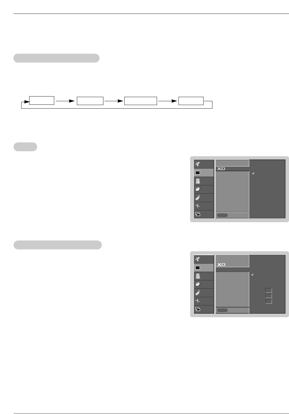
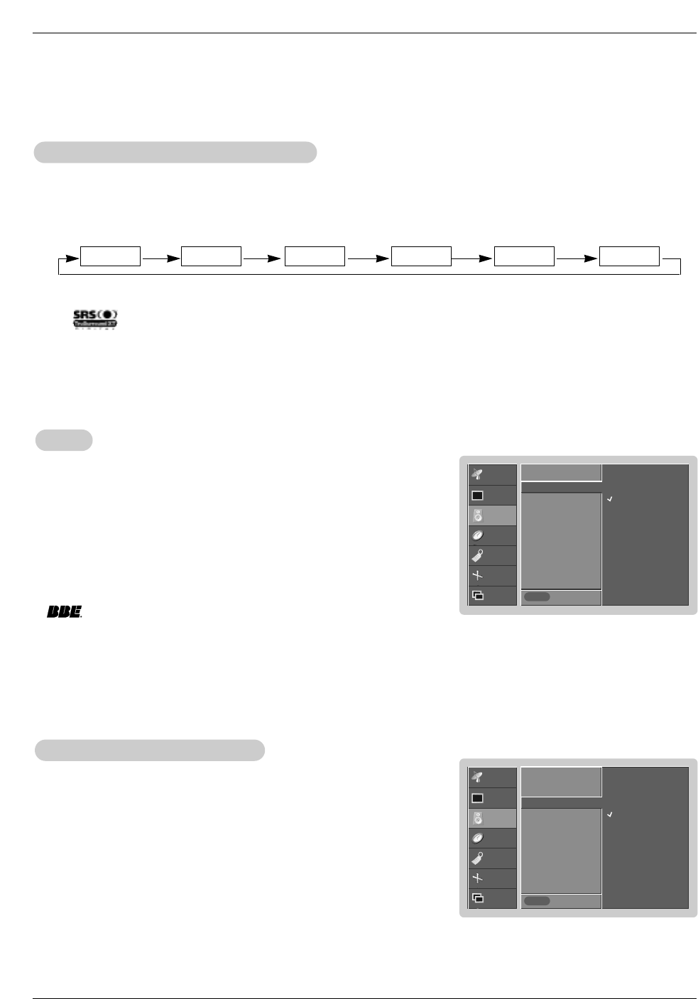
1. Press the DASP button repeatedly to select the appropriate sound setup as shown below.
DASP
DASP (Digital
(Digital Auto Sound Processing)
Auto Sound Processing)
•You can also adjust DASP in the SOUND menu.
•SRS TSXT, Flat, Music, Movie, and Sports are preset for good sound quality at the factory and cannot be changed.
•is a trademark of SRS Labs, Inc.
•TruSurround XT technology is incorporated under license from SRS Labs, Inc.
Flat Music Movie Sports OffSRS TSXT
- This function lets you enjoy the best sound without any special adjustment because the TV has the appropriate
sound options based on the program content.
- If you adjust sound options (Treble and Bass) manually, DASP automatically changes to Off.
- AVL maintains an equal sound level; even if you change channels.
1. Press the MENU button and then use D / Ebutton to select the SOUND menu.
2. Press the Gbutton and then use D / Ebutton to select AV L .
3. Press the Gbutton and then use D / Ebutton to select On or Off.
4. Press the ENTER button to save.
A
AVL
VL (Auto V
(Auto Volume Leveler)
olume Leveler)
1. Press the MENU button and then use D / Ebutton to select the SOUND menu.
2. Press the Gbutton and then use D / Ebutton to select BBE.
3. Press the Gbutton and then use D / Ebutton to select On or Off.
4. Press the ENTER button to save.
BBE
BBE
- BBE High Definition Sound restores clarity and presence for better speech
intelligibility and music realism.
•Manufactured under license from BBE Sound, Inc.
•Treble, Bass or BBE aren’t suitable for SRS TSXT mode.
Owner’s Manual 21
Operation
CHANNEL
PICTURE
SOUND
TIMER
SPECIAL
SCREEN
PIP/DW Prev.
MENU
DASP
BBE
AVL
Balance 0 G
Treble 50
Bass 50
L R
1. Press the MTS button repeatedly.
Stereo/SAP
Stereo/SAP Broadcasts Setup
Broadcasts Setup
•Select mono sound mode if the signal is not clear or in poor signal reception areas.
•Stereo, SAP modes are available only if included on the broadcast signal.
Mono Stereo SAP
- The TV can receive MTS stereo programs and any SAP (Secondary Audio Program) that accompanies the
stereo program; if the broadcaster transmits one additional sound signal in addition to the original one.
- Mono: The primary language is heard from left and right speakers. Signal mode is mono.
- Stereo: The primary language is heard from left and right speakers. Signal mode is stereo.
- SAP: The secondary language is heard from left and right speakers in mono sound.
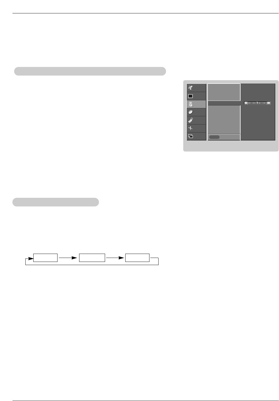
1. Press the MENU button and then use D / Ebutton to select the SOUND menu.
2. Press the Gbutton and then use D / Ebutton to select the desired sound option
(Balance,Treble,Bass).
3. Press the Gbutton and then use F / Gbutton to make appropriate adjustments.
4. Press the ENTER button to save.
Manual Sound Control (
Manual Sound Control (DASP off option and balance)
option and balance)
- You can adjust sound options Balance, Treble, and Bass to the levels you prefer.
22 Plasma TV
Operation
T
Timer Menu Options
imer Menu Options
CHANNEL
PICTURE
SOUND
TIMER
SPECIAL
SCREEN
TWIN Prev.
MENU
- - : - - AM
Clock G
Off timer
On timer
Auto off
CHANNEL
PICTURE
SOUND
TIMER
SPECIAL
SCREEN
PIP/DW Prev.
MENU
On
Off
6 : 30 AM
Volume TV 2
Ch. 17
Clock
Off timer
On timer G
Auto off
CHANNEL
PICTURE
SOUND
TIMER
SPECIAL
SCREEN
PIP/DW Prev.
MENU
On
Off
Clock
Off timer
On timer
Auto off G
- Timer function operates only if current time has been set.
- Off-Timer function overrides On-Timer function if they are set both set to the same time.
- The TV must be in standby mode for the On-Timer to work.
- If you do not press any button within 2 hours after the TV turns on with the On Timer function, the TV will automatically revert to
standby mode.
On/Of
On/Off
f T
Timer Setup
imer Setup
1. Press the MENU button and then use D / Ebutton to select the TIMER menu.
2. Press the Gbutton and then use D / Ebutton to select Off timer or On timer.
3. Press the Gbutton and then use D / Ebutton to select On.
• To cancel On/Off timer function, select Off.
4. Press the Gbutton and then use D / Ebutton to set the hour.
5. Press the Gbutton and then use D / Ebutton to set the minutes.
6. For only On timer function
Press the Gbutton and then use D / Ebutton to select the channel at turn-on.
Press the Gbutton and then use D / Ebutton to set the sound level at turn-on.
7. Press the ENTER button to save.
Clock Setup
Clock Setup
- If current time setting is wrong, reset the clock manually.
1. Press the MENU button and then use D / Ebutton to select the TIMER menu.
2. Press the Gbutton and then use D / Ebutton to select Clock.
3. Press the Gbutton and then use D / Ebutton to set the hour.
4. Press the Gbutton and then use D / Ebutton to set the minutes.
5. Press the ENTER button to save.
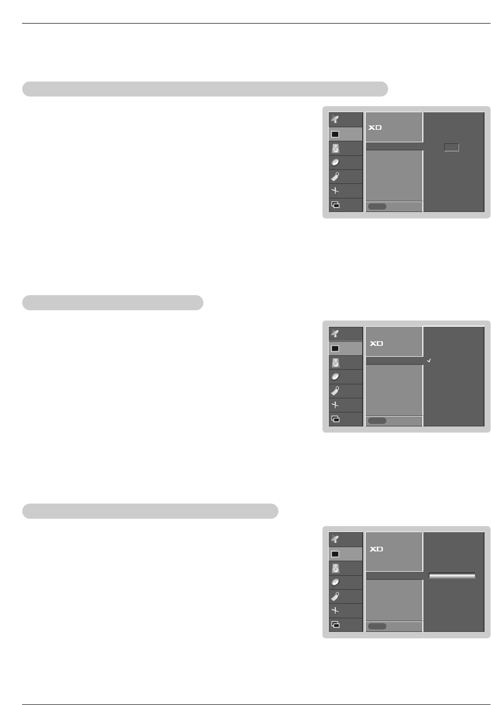
Auto Of
Auto Off
f
- If set to on and there is no input signal, the TV turns off automatically after 10
minutes.
1. Press the MENU button and then use D / Ebutton to select the TIMER menu.
2. Press the Gbutton and then use D / Ebutton to select Auto off.
3. Press the Gbutton and then use D / Ebutton to select On or Off.
4. Press the ENTER button to save.
Sleep
Sleep T
Timer
imer
- The Sleep Timer turns the TV off at the preset time. Note that this setting is cleared when the TV is turned off.
1. Press the SLEEP button repeatedly to select the number of minutes. First the Off option appears on the screen,
followed by the following sleep timer options: 10, 20, 30, 60, 90, 120, 180, and 240 minutes.
2. When the number of minutes you want is displayed on the screen, press the OK button. The timer begins to count
down from the number of minutes selected.
3. To check the remaining minutes before the TV turns off, press the SLEEP button once.
4. To cancel the Sleep Timer, press the SLEEP button repeatedly to select Off.
Owner’s Manual 23
Operation
Key Lock
Key Lock
- The TV can be set up so that it can only be used with the remote control.
- This feature can be used to prevent unauthorized viewing by locking out the front panel controls.
- This TV is programmed to remember which option it was last set to even if you turn the TV off.
Special Menu Options
Special Menu Options
1. Press the MENU button and then use D / Ebutton to select the SPECIAL menu.
2. Press the Gbutton and then use D / Ebutton to select Key lock.
3. Press the Gbutton and then use D / Ebutton to select On or Off.
4. Press the ENTER button to save.
• With the Key lock On, the display ‘ Key lock’appears on the screen if any
button on the front panel is pressed.
W
ISM (Image Sticking Minimization) Method
ISM (Image Sticking Minimization) Method
- A frozen still picture from a PC/video game displayed on the screen for prolonged periods will result in a ghost image remaining
even when you change the image. Avoid allowing a fixed image to remain on the TV's screen for a long period of time.
1. Press the MENU button and then use D / Ebutton to select the SPECIAL menu.
2. Press the Gbutton and then use D / Ebutton to select ISM Method.
3. Press the Gbutton and then use D / Ebutton to select either Normal, White
wash, Orbiter or Inversion.
• Normal
If image sticking is never a problem, ISM is not necessary - set to Normal.
• White wash
White Wash removes permanent images from the screen. Note: An excessive
permanent image may be impossible to clear entirely with White Wash. To
return to normal viewing, press any button.
• Orbiter
Orbiter may help prevent ghost images. However, it is best not to allow any
fixed image to remain on the screen. To avoid a permanent image on the
screen, the image will move every 2 minutes: Right →Right → Downside →
Downside →Left →Left →Upside →Upside.
• Inversion
Inversion will automatically invert the TV panel color every 30 minutes.
4. Press the ENTER button to save.
CHANNEL
PICTURE
SOUND
TIMER
SPECIAL
SCREEN
PIP/DW Prev.
MENU
On
Off
Language
Key lock G
ISM Method
Low power
Set ID
Caption / Text
Captions
Demo
CHANNEL
PICTURE
SOUND
TIMER
SPECIAL
SCREEN
PIP/DW Prev.
MENU
Normal
White wash
Orbiter
Inversion
Language
Key lock
ISM Method G
Low power
Set ID
Caption / Text
Captions
Demo

24 Plasma TV
Operation
Special Menu Options continued
Special Menu Options continued
Low Power
Low Power
- Low power reduces the plasma display power consumption.
1. Press the MENU button and then use D / Ebutton to select the SPECIAL menu.
2. Press the Gbutton and then use D / Ebutton to select Low power.
3. Press the Gbutton and then use D / Ebutton to select On or Off.
• When you select On, the screen darkens.
4. Press the ENTER button to save.
CHANNEL
PICTURE
SOUND
TIME
SPECIAL
SCREEN
TWIN
LOCK Prev.
MENU
On
Off
Language
Key lock
ISM Method
Low power G
Set ID
Caption / Text
Captions
Demo
CHANNEL
PICTURE
SOUND
TIME
SPECIAL
SCREEN
TWIN
LOCK Prev.
MENU
To start
Language
Key lock
ISM Method
Low power
Set ID
Caption / Text
Captions
Demo G
XD Demo
XD Demo
1. Press the MENU button and then use D / Ebutton to select the SPECIAL menu.
2. Press the Gbutton and then use D / Ebutton to select Demo.
3. Press the Gbutton to begin
XD Demo
.
4. Press the MENU button to stop
XD Demo
.
- Use it to see the difference between XD Demo on and XD Demo off.
Owner’s Manual 25
Operation
CHANNEL
PICTURE
SOUND
TIME
SPECIAL
SCREEN
TWIN Prev.
MENU
CC1
CC2
CC3
CC4
Text1
Text2
Text3
Text4
Language
Key lock
ISM Method
Low power
Set ID
Caption / Text G
Captions
Demo
Caption/T
Caption/Text
ext
- Low power reduces the plasma display power consumption.
1. Press the MENU button and then use D / Ebutton to select the OPTION menu.
2. Press the Gbutton and then use D / Ebutton to select Caption / Text.
3. Press the Gbutton and then use D / Ebutton to select caption: CC1, CC2, CC3,
CC4, Text1, Text2, Text3, or Text4.
• CAPTION
The term for the words that scroll across the bottom of the TV screen; usually
the audio portion of the program provided for the hearing impaired.
• TEXT
The term for the words that appear in a large black frame and almost cover
the entire screen; usually messages provided by the broadcaster.
4. Press the ENTER button to save.
Closed Captions
Closed Captions
2. An old, bad, or illegally recorded tape is being played.
3. Strong, random signals from a car or airplane interfere with
the TV signal.
4. The signal from the antenna is weak.
5. The program wasn’t captioned when it was produced, trans-
mitted, or taped.
Closed captioning is a process which converts the audio portion
of a television program into written words which then appear as
subtitles on the television screen. Closed captions allow viewers
to read the dialogue and narration of television programs.
Using Closed Captions
Captions are the subtitles of the dialogue and narration of tele-
vision programs. For prerecorded programs, program dialogue
can be arranged into captions in advance. Its possible to caption
a live program by using a process called real-time captioning,
which creates captions instantly. Real-time captioning is nor-
mally done by professional reporters using a machine shorthand
system and computer for trans-
lation into English.
Captioning is an effective sys-
tem for the hearing-impaired,
and it can also aid in teaching
language skills.
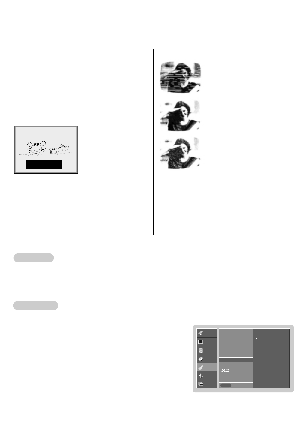
• The picture at left shows a
typical caption.
Caption Tips
•Not all TV broadcasts include closed caption signals.
•Sometimes TV stations broadcast four different caption sig-
nals on the same channel. By selecting CC 1 to CC 2, you
can choose which signal you view. CC 1 is usually the signal
with the captions, while Another mode might show demon-
stration or programming information.
•Your TV might not receive caption signals normally in the fol-
lowing situations.
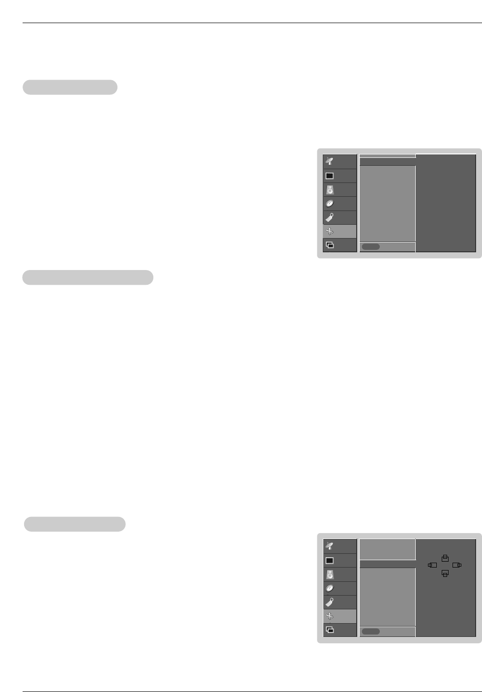
• IGNITION:
Picture may flutter, drift, suffer from black
spots, or horizontal streaking. Usually
caused by interference from automobile
ignition systems, neon lamps, electrical
drills, and other electrical appliances.
• GHOSTS:
Ghosts are caused when the TV signal
splits and follows two paths. One is the
direct path and the other is reflected off
tall buildings, hills or other objects.
Changing the direction or position of the
antenna may improve reception.
• SNOW:
If your receiver is located at the weak,
fringe area of a TV signal, your picture
may be marred by small dots. It may be
necessary to install a special antenna to
improve the picture.
FOLLOW ME
1. Poor reception conditions are encountered:
Captions
Captions
1. Use the CAPTION button repeatedly to select Caption Off, EZ Mute, or On.
• EZ Mute shows the selected captions option (if available on program) when the TV sound is muted
2. Press the ENTER button to save.
26 Plasma TV
Operation
Screen Menu Options
Screen Menu Options
CHANNEL
PICTURE
SOUND
TIMER
SPECIAL
SCREEN
PIP/DW Prev.
MENU
To set
Auto config. G
ARC
Position
Manual config
Reset
CHANNEL
PICTURE
SOUND
TIMER
SPECIAL
SCREEN
PIP/DW Prev.
MENU
Auto config.
ARC
Position G
Manual config
Reset
D
FG
E
Auto
Auto Adjustment
Adjustment
- RGB (PC) mode only; This function doesn’t work for RGB-DTV mode.
- Automatically adjusts picture position and minimizes image shaking.
- After adjustment, if the image is still not correct, your TV is functioning properly but needs further adjustment.
- The Auto config. and Manual config. are not active in DVI mode.
1. Press the MENU button and then use D /Ebutton to select the SCREEN menu.
2. Press the Gbutton and then use D /Ebutton to select Auto config..
3. Press the Gbutton to run Auto configure.
• When Auto config. has finished, OK will be shown on screen.
• If the position of the image is still not correct, try Auto adjustment again.
4. In RGB (PC) mode, if the image needs to be adjusted more after using Auto
config., you can make further adjustments with the Manual config. option.
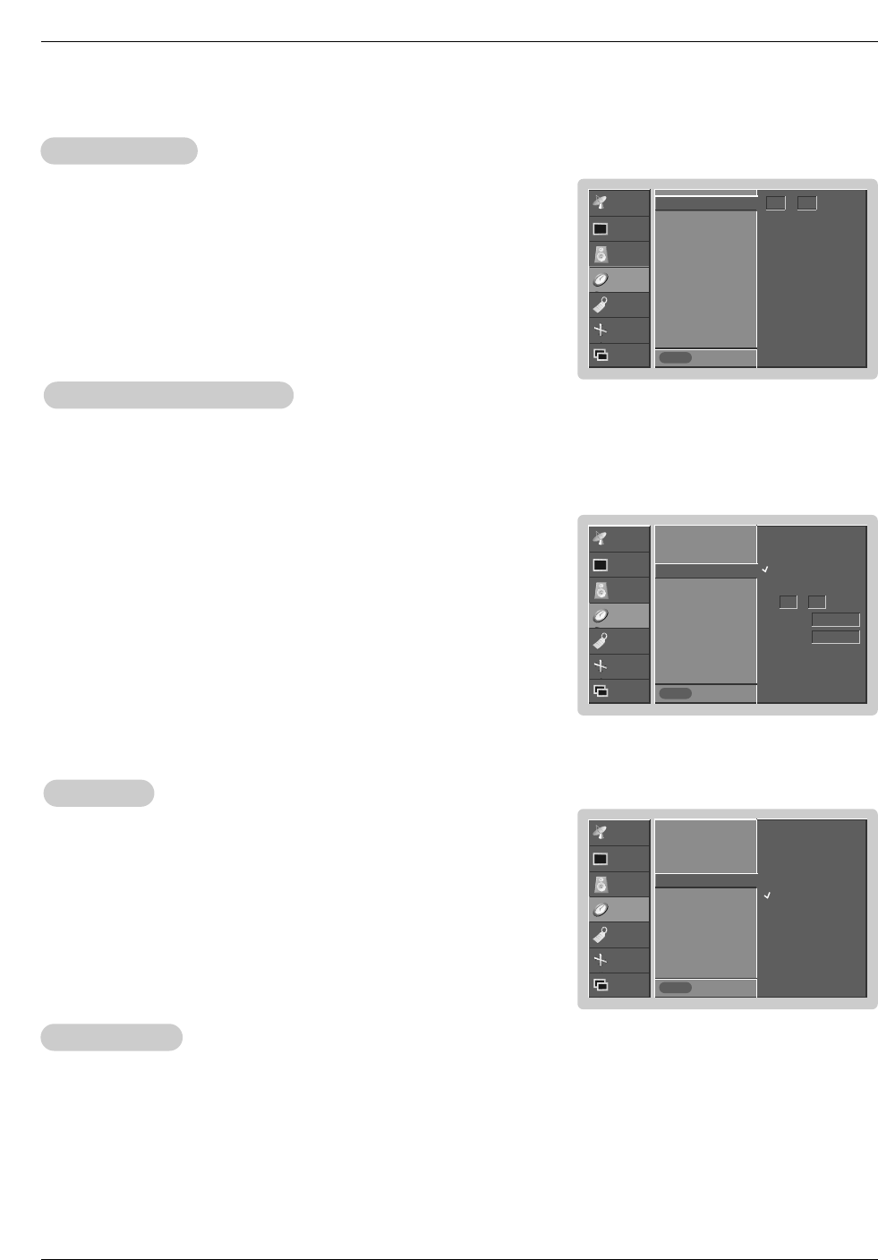
Setting Picture Format
Setting Picture Format
- Caution: If a 4:3 fixed image is on the screen for a long time, it may remain visible.
- Set every aspect ratio for TV, Video, Component 480i sources.
- Use 4:3, or 16:9 for other RGB-PC and DVI-PC sources.
- Horizon is not available for Component (480p,720p,1080i), DTV (480p,720p,1080i) sources.
1. Press the ARC button repeatedly to select the desired picture format. You can also adjust ARC in the SCREEN menu.
• 4:3
Choose 4:3 when you want to view a picture with an original 4:3 aspect ratio, with black bars appearing at both the
left and right sides.
• 16:9
Choose 16:9 when you want to adjust the picture horizontally, in a linear proportion to fill the entire screen.
• Horizon
Choose Horizon when you want to adjust the picture in a non-linear proportion, that is, more enlarged at both sides,
to create a spectacular view.
• Zoom
- Choose Zoom when you want to view the picture without any alteration. However, the top and bottom portions of the
picture will be cropped.
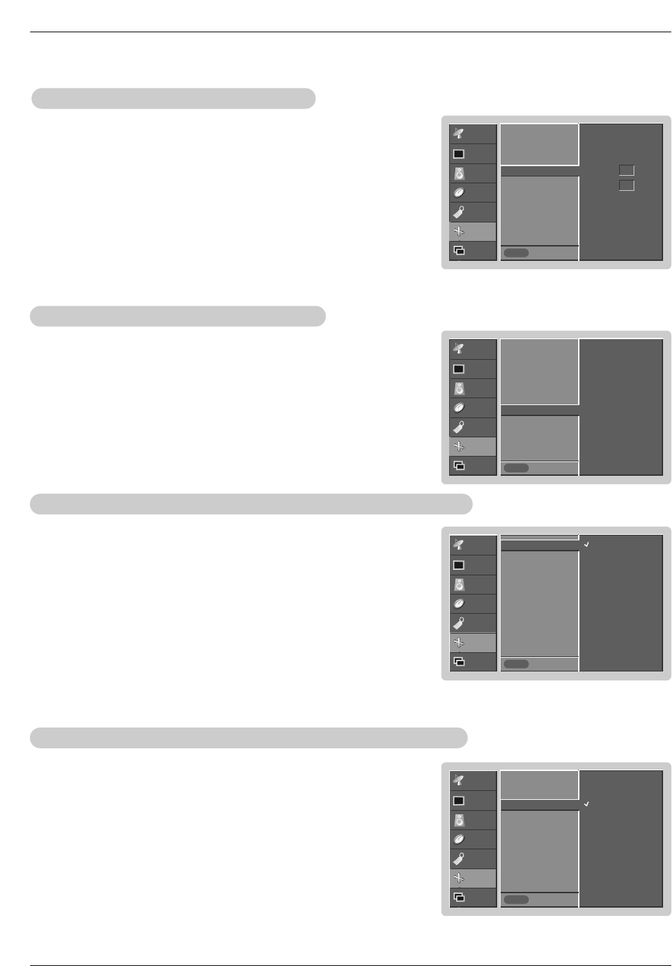
1. Press the MENU button and then use D / Ebutton to select the SCREEN menu.
2. Press the Gbutton and then use D / Ebutton to select Position.
3. Press the Gbutton and then use D / E / F / G button to adjust the position.
4. Press the ENTER button to save.
Screen Position
Screen Position
- This function works in the following modes:
RGB-PC, RGB-DTV (480p,720p,1080i), DVI-DTV (480p,720p,1080i), COM-
PONENT (480p,720p,1080i).
Owner’s Manual 27
CHANNEL
PICTURE
SOUND
TIMER
SPECIAL
SCREEN
PIP/DW Prev.
MENU
TV
VCR
Screen adj. G
ARC
Cinema
YNR
Reset
CHANNEL
PICTURE
SOUND
TIMER
SPECIAL
SCREEN
PIP/DW Prev.
MENU
On
Off
Screen adj.
ARC
Cinema G
YNR
Reset
CHANNEL
PICTURE
SOUND
TIMER
SPECIAL
SCREEN
PIP/DW Prev.
MENU
Auto config.
ARC
Position
Manual config G
Reset
Phase 0
Clock 0
CHANNEL
PICTURE
SOUND
TIMER
SPECIAL
SCREEN
PIP/DW Prev.
MENU
Auto config.
ARC
Position
Manual config
Reset
VGA Mode G640x480
848x480
852x480
Screen
Screen Adjustments (TV
Adjustments (TV, V
, Video1-2 and Component 480i mode only)
ideo1-2 and Component 480i mode only)
- Use this function to correct jittering or picture instability while viewing a video
tape.
1. Press the MENU button and then use D /Ebutton to select the SCREEN menu.
2. Press the Gbutton and then use D /Ebutton to select Screen adj..
3. Press the Gbutton and then use D /Ebutton to select TV or VCR.
• Select the VCR option if watching a VCR.
• Select the TV option for other equipment. (Except VCR)
4. Press the ENTER button to save.
- Sets up the TV for the best picture appearance for viewing movies.
1. Press the MENU button and then use D / Ebutton to select the SPECIAL menu.
2. Press the Gbutton and then use D / Ebutton to select Cinema..
3. Press the Gbutton and then use D / Ebutton to select On or Off.
4. Press the ENTER button to save.
Cinema Mode Setup (TV
Cinema Mode Setup (TV, V
, Video1-2 and Component 480i mode only)
ideo1-2 and Component 480i mode only)
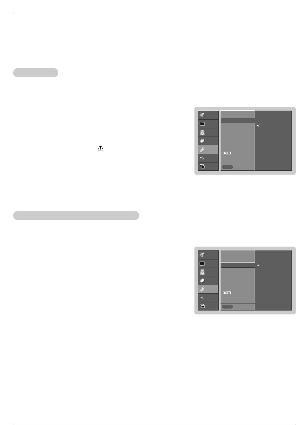
Manual Configure (RGB-PC mode only)
Manual Configure (RGB-PC mode only)
- If the image still isn’t clear after auto adjustment and especially if characters are
still jittery, adjust the picture Phase manually.
- To correct the screen size, adjust Clock.
1. Press the MENU button and then use D / Ebutton to select the SCREEN menu.
2. Press the Gbutton and then use D / Ebutton to select Manual config..
3. Press the Gbutton and then use D / Ebutton to to select Phase or Clock.
4. Use the F / Gbutton to make appropriate adjustments.
• The Phase adjustment range is 0 ~ 30.
• The Clock adjustment range is -127 ~ +128.
5. Press the ENTER button to save.
Selecting VGA
Selecting VGA mode (RGB-PC mode only)
mode (RGB-PC mode only)
- To see a normal picture, match the resolution of RGB mode and selection of
VGA mode.
1. Press the MENU button and then use D /Ebutton to select the SCREEN menu.
2. Press the Gbutton and then use D /Ebutton to select VGA Mode.
3. Press the Gbutton and then use D /Ebutton to select the desired VGA resolu-
tion.
4. Press the ENTER button to save.
28 Plasma TV
CHANNEL
PICTURE
SOUND
TIMER
SPECIAL
SCREEN
PIP/DW Prev.
MENU
On
Off
Screen adj.
ARC
Cinema
YNR G
Reset
CHANNEL
PICTURE
SOUND
TIMER
SPECIAL
SCREEN
PIP/DW Prev.
MENU
To set
Screen adj.
ARC
Cinema
YNR
Reset G
Screen Menu Options continued
Screen Menu Options continued
- Use YNR to reduce the picture noise that may appear on the screen.
Luminance Noise Reduction (TV
Luminance Noise Reduction (TV, V
, Video 1-2 and Component 480i modes only)
ideo 1-2 and Component 480i modes only)
1. Press the MENU button and then use D /Ebutton to select the SCREEN menu.
2. Press the Gbutton and then use D / Ebutton to select YNR.
3. Press the Gbutton and then use D / Ebutton to select On or Off.
4. Press the ENTER button to save.
1. Press the MENU button and then use D / Ebutton to select the SCREEN menu.
2. Press the Gbutton and then use D / Ebutton to select Reset.
3. Press the Gbutton.
•You can initialize Position, Split zoom, PIP Transparency, PIP position, PIP size
and sub picture size for double window.
Initializing (Reset to original factory value)
Initializing (Reset to original factory value)
- Reset is unique to each function: Manual config., Position, Split zoom, PIP posi-
tion and sub picture size for double window.
- Use the Reset option to initialize the adjusted settings.
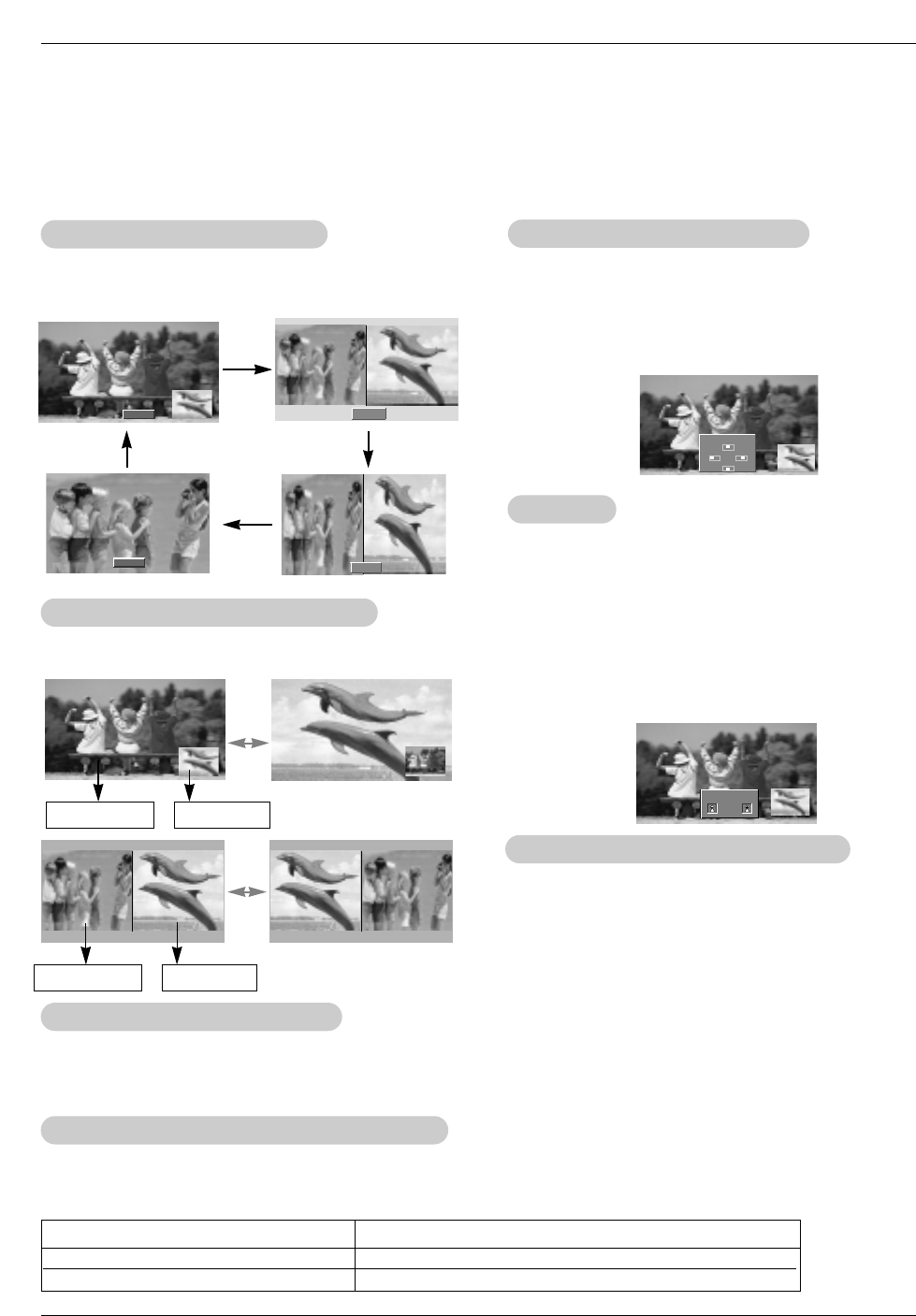
Split Zoom
Split Zoom
- Enlarges the picture in correct proportions.
- Split Zoom can be used for all input sources.
- In 2-Split Zoom mode, you can only move the image up or down.
- If an image is enlarged, a section can be viewed without using Split Zoom.
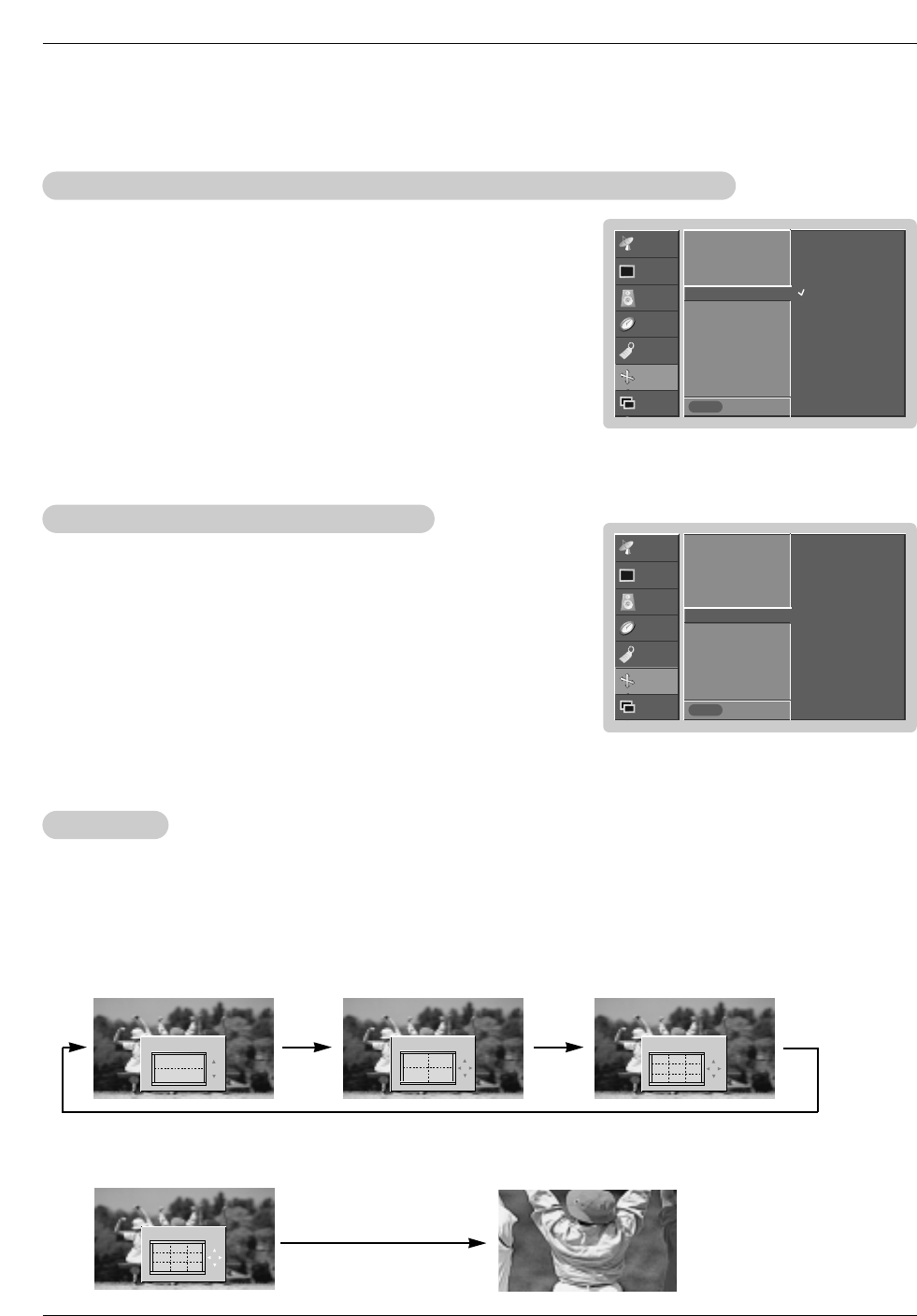
1. Press the SPLIT ZOOM button repeatedly to select either 2, 4, or 9 Split Zoom.
2. Press the number button corresponding to the section you wish to enlarge. You can move within the enlarged pic-
ture using the D / E / F / Gbutton. To return to normal viewing, press the SPLIT ZOOM button again.
Example of choosing 5. Section 5 is enlarged to fill
the screen.
1
4
2-Split zoom
1
4
2
5
4-Split zoom
123
456
789
9-Split zoom
123
456
789
9-Split zoom
Owner’s Manual 29
Operation
- PIP lets you view 2 different inputs pictures (sources) on your TV screen at the same time. One source will be large, and the
other source will show a smaller inset image.
- Double Window mode splits the screen into 2, allowing 2 picture sources to be shown on the TV screen at the same time. Each
source is given half the screen.
PIP
PIP (Picture-In-Picture)/Double W
(Picture-In-Picture)/Double Window Feature
indow Feature
W
Watching PIP/Double W
atching PIP/Double Window
indow Moving the PIP
Moving the PIP (PIP
(PIP Mode only)
Mode only)
Press the POSITION button.
Press the D / E/ F / Gbutton repeatedly until desired posi-
tion is achieved. The sub picture moves up/down/left/right.
•You can also move the PIP position with Win.position in
the PIP/DW menu.
◀▶
▲
▼
Win.position
DW 1
DW 2
Press the PIP/DW button to access the sub picture. Each
press of PIP changes the PIP options as shown below.
PIP
Off
TV Program selection for PIP
TV Program selection for PIP
Press the PIPCH+ / PIPCH- button to select a channel for
the sub picture in PIP mode.
Swapping the PIP
Swapping the PIP/
/Double W
Double Window
indow
Use the SWAP button to switch the main and sub pictures.
Selecting an Input Signal Source for PIP
Selecting an Input Signal Source for PIP/Double W
/Double Window
indow
Use the PIP INPUT button to select the input source for the
sub picture. Each press of PIP INPUT button changes the
PIP source.
Main Picture Sub Picture
Main Picture Sub Picture
PIP
PIP Size
Size
Press the WIN.SIZE button and then use F / Gbutton to
change the sub picture size.
•Using the Win.size function in Double Window mode, main
and sub picture sizes are changed simultaneously.
Using the Win.size function in PIP mode, sub picture size
is changed.
•You can also change the sub picture size with Win.size in
the PIP/DW menu.
Win.size
F G
PIP
PIP T
Transparency (PIP
ransparency (PIP Mode only)
Mode only)
- To make the PIP clear or opaque
1. Press the MENU button and then use D / Ebutton to
select the PIP/DW menu.
2. Press the Gbutton and then use D / Ebutton to select PIP
Transparency .
3. Press the Gbutton and then use D / Ebutton to adjust
PIP transparency.
4. Use the F / Gbutton to make appropriate adjustments.
• The adjustment range of PIP Transparency is 0 ~ 10.
5. Press the ENTER button to save.
Main Picture Source Available Sub Picture Sources
TV, Video 1-2, Component 480i
Component 480p/720p/1080i, RGB and DVI TV, Video 1-2, Component 480i/480p/720p/1080i, RGB and DVI
TV, Video 1-2, Component 480i
30 Plasma TV
External Control Device Setup
No. Pin name
1 No connection
2 RXD (Receive data)
3 TXD (Transmit data)
4 DTR (DTE side ready)
5 GND
6 DSR (DCE side ready)
7 RTS (Ready to send)
8 CTS (Clear to send)
9 No Connection
1
5
6
9
2
3
5
4
6
7
8
RXD
TXD
GND
DTR
DSR
RTS
CTS
TXD
RXD
GND
DSR
DTR
CTS
RTS
PC
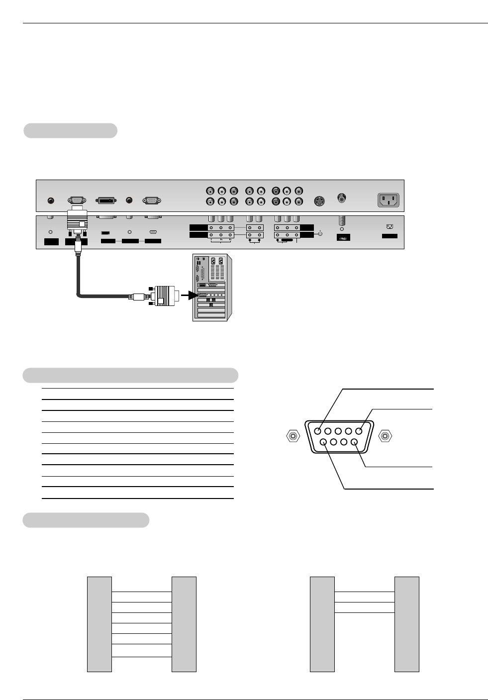
7-Wire Configurations
(Standard RS-232C cable)
D-Sub 9
3
2
5
6
4
8
7
PDP
D-Sub 9
2
3
5
4
6
7
8
RXD
TXD
GND
DTR
DSR
RTS
CTS
TXD
RXD
GND
DTR
DSR
RTS
CTS
PC
3-Wire Configurations
(Not standard)
D-Sub 9
3
2
5
4
6
7
8
PDP
D-Sub 9
- Connect the RS-232C input jack to an external control device (such as a computer or an A/V control system)
and control the Monitor’s functions externally.
- Connect the serial port of the control device to the RS-232C jack on the Monitor back panel.
- RS-232C connection cables are not supplied with the Monitor.
T
Type of Connector; D-Sub 9-Pin Male
ype of Connector; D-Sub 9-Pin Male
RS-232C Configurations
RS-232C Configurations
External Control Device Setup
External Control Device Setup
RS-232C Setup
RS-232C Setup
RGB INPUT
Antenna
AUDIO INPUT
DVI INPUT
S-VIDEO
REMOTE
CONTROL
AC INPUT
AUDIOVIDEO
COMPONENT
INPUT 2
COMPONENT
INPUT 1
MONITOR
OUTPUT
A/V
INPUT 1
RL
AUDIO VIDEO
R
RS-232C INPUT
(CONTROL/SERVICE)
L/MONO
PC
Owner’s Manual 31
External Control Device Setup
CHANNEL
PICTURE
SOUND
TIME
SPECIAL
SCREEN
TWIN Prev.
MENU
Language
Key lock
ISM Method
Low power
Set ID G
Caption / Text
Captions
Demo
1
Set ID
Set ID
- Use this function to specify a monitor ID number.
- Refer to ‘Real Data Mapping 1’. See page 32.
• Baud rate :9600 bps (UART)
• Data length : 8 bits
• Parity : None
* Use a crossed (reverse) cable.
• Stop bit : 1 bit
• Communication code : ASCII code
Communication Parameters
Communication Parameters
1. Press the MENU button and then use D /Ebutton to select the SPECIAL menu.
2. Press the Gbutton and then use D /Ebutton to select Set ID.
3. Press the Gbutton and then use F / Gbutton to adjust Set ID to choose the
desired monitor ID number. The adjustment range of Set ID is 1 ~ 99.
4. Press the ENTER button to save.
Transmission
* [Command 1]: First command to control PDP set. (j, k or m)
* [Command 2]: Second command to control PDP set.
* [Set ID]: You can adjust the set ID to choose desired monitor
ID number in Special menu. Adjustment range is 1
~ 99. When selecting Set ID ‘0’, every connected
PDP set is controlled. Set ID is indicated as deci-
mal (1~99) on menu and as Hexa decimal
(0x0~0x63) on transmission/receiving protocol.
* [DATA]: To transmit command data.
Transmit ‘FF’data to read status of command.
* [Cr]: Carriage Return
ASCII code ‘0x0D’
* [ ]: ASCII code ‘space (0x20)’
[Command1][Command2][ ][Set ID][ ][Data][Cr]
T
Transmission / Receiving Protocol
ransmission / Receiving Protocol
OK Acknowledgement
* The Monitor transmits ACK (acknowledgement) based on
this format when receiving normal data. At this time, if the
data is data read mode, it indicates present status data. If
the data is data write mode, it returns the data of the PC
computer.
[Command2][ ][Set ID][ ][OK][Data][x]
Error Acknowledgement
* The Monitor transmits ACK (acknowledgement) based on
this format when receiving abnormal data from non-viable
functions or communication errors.
[Command2][ ][Set ID][ ][NG][Data][x]
Data 1: Illegal Code
2: Not supported function
3: Wait more time
01. Power k a 0 ~ 1
02. Input Select k b 0 ~ 6
03. Aspect Ratio k c 0 ~ 3
04. Screen Mute k d 0 ~ 1
05. Volume Mute k e 0 ~ 1
06. Volume Control k f 0 ~ 64
07. Contrast k g 0 ~ 64
08. Brightness k h 0 ~ 64
09. Color k i 0 ~ 64
10. Tint k j 0 ~ 64
11. Sharpness k k 0 ~ 64
12. OSD Select k l 0 ~ 1
13.
Remote Control Lock Mode
k m 0 ~ 1
14. PIP/DW k n 0 ~ 3
15. Split Zoom k p 0 ~99
16. PIP Position k q 0 ~ 3
17. Treble k r 0 ~ 64
18. Bass k s 0 ~ 64
19. Balance k t 0 ~ 64
20. Color Temperature k u 0 ~ 3
21. Red Adjustment k v 0 ~ 3C
22. Green Adjustment k w 0 ~ 3C
23. Blue Adjustment k $ 0 ~ 3C
24. PIP Input Source k y 0 ~ 6
25. Abnormal State k z 0 ~ a
26. ISM Method j p 0 ~ 3
27. Low Power j q 0 ~ 1
28. Orbiter Time Setting j r 1 ~ FE
29. Orbiter Pixel Setting j s 1~9
30. Picture Size j t 0 ~14
31. Auto Config j u 1
COMMAND 1 COMMAND 2 DATA
(Hexadecimal)
Command Reference List
Command Reference List
32. Tune Command m a 01 ~ 7D 0 0 mainsub/TuneBand
33. Channel Add/Del m b 0 ~ 1
34. Key m c Key code
COM-
MAND 2
COM-
MAND 1 DATA 0
(Hexadecimal)
DATA 1
(Hexadecimal)
DATA 2
(Hexadecimal)
DATA 3
(Hexadecimal)

32 Plasma TV
External Control Device Setup
02. Input Select (Command2:b) (Main Picture Input)
GTo select input source for the TV.
You can also select an input source using the TV/VIDEO
button on the TV's remote control.
Transmission
Data 0 : TV
1 : Video 1
2 : Video 2
3 : Component 1
4 : Component 2
5 : RGB
6 : DVI
[k][b][ ][Set ID][ ][Data][Cr]
Acknowledgement
[b][ ][Set ID][ ][OK][Data][x]
01. Power (Command2:a)
GTo control Power On/Off of the TV.
Transmission
Data 0 : Power Off 1 : Power On
[k][a][ ][Set ID][ ][Data][Cr]
Acknowledgement
[a][ ][Set ID][ ][OK][Data][x]
* In a like manner, if other functions transmit ‘FF’data
based on this format, Acknowledgement data feedback
presents status about each function.
* Real data mapping 1
0 : Step 0
A : Step 10 (SET ID 10)
F : Step 15 (SET ID 15)
10 : Step 16 (SET ID 16)
63 : Step 99 (SET ID 99)
64 : Step 100
05. Volume Mute (Command2:e)
GTo control volume mute on/off.
You can also adjust mute using the MUTE button on
remote control.
Transmission
Data 0 : Volume mute on (Volume off)
1 : Volume mute off (Volume on)
[k][e][ ][Set ID][ ][Data][Cr]
Acknowledgement
[e][ ][Set ID][ ][OK][Data][x]
03. Aspect Ratio (Command2:c) (Main picture format)
GTo adjust the screen format.
You can also adjust the screen format using the ARC
(Aspect Ratio Control) button on remote control or in the
Screen menu.
Transmission
Data 0 : Normal screen (4:3)
1 : Wide screen (16:9)
2 : Horizon
3 : Zoom
[k][c][ ][Set ID][ ][Data][Cr]
Acknowledgement
[c][ ][Set ID][ ][OK][Data][x]
04. Screen Mute (Command2:d)
GTo select screen mute on/off.
Transmission
Data 0 : Screen mute off (Picture on)
1 : Screen mute on (Picture off)
[k][d][ ][Set ID][ ][Data][Cr]
Acknowledgement
[d][ ][Set ID][ ][OK][Data][x]
06. Volume Control (Command2:f)
GTo adjust volume.
You can also adjust volume with the volume buttons
on remote control.
Transmission
Data Min : 0 ~ Max : 64
•Refer to ‘Real data mapping 1’as shown below.
[k][f][ ][Set ID][ ][Data][Cr]
Acknowledgement
[f][ ][Set ID][ ][OK][Data][x]
07. Contrast (Command2:g)
GTo adjust screen contrast.
You can also adjust contrast in the Picture menu.
Transmission
Data Min : 0 ~ Max : 64
•Refer to ‘Real data mapping 1’as shown below.
[k][g][ ][Set ID][ ][Data][Cr]
Acknowledgement
[g][ ][Set ID][ ][OK][Data][x]
08. Brightness (Command2:h)
GTo adjust screen brightness.
You can also adjust brightness in the Picture menu.
Transmission
Data Min : 0 ~ Max : 64
•Refer to ‘Real data mapping 1’as shown below.
[k][h][ ][Set ID][ ][Data][Cr]
Acknowledgement
[h][ ][Set ID][ ][OK][Data][x]

Owner’s Manual 33
External Control Device Setup
17. Treble (Command2:r)
GTo adjust treble.
You can also adjust treble in the Sound menu.
Transmission
Data Min: 0 ~ Max: 64
•Refer to ‘Real data mapping 1’. See page 32.
[k][r][ ][Set ID][ ][Data][Cr]
Acknowledgement
[r][ ][Set ID][ ][OK][Data][x]
09. Color (Command2:i)
GTo adjust the screen color.
You can also adjust color in the Picture menu.
Transmission
Data Min : 0 ~ Max : 64
•Refer to ‘Real data mapping 1’. See page 32.
[k][i][ ][Set ID][ ][Data][Cr]
Acknowledgement
[i][ ][Set ID][ ][OK][Data][x]
10. Tint (Command2:j)
GTo adjust the screen tint.
You can also adjust tint in the Picture menu.
Transmission
Data Red : 0 ~ Green : 64
•Refer to ‘Real data mapping 1’. See page 32.
[k][j][ ][Set ID][ ][Data][Cr]
Acknowledgement
[j][ ][Set ID][ ][OK][Data][x]
13. Remote Control Lock Mode (Command2:m)
GTo lock the remote control and the front panel controls on
the monitor.
Transmission
[k][m][ ][Set ID][ ][Data][Cr]
Acknowledgement
Data 0: Lock off 1: Lock on
•If you’re not using the remote control and front panel controls
on the monitor, use this mode. When main power is on/off,
remote control lock is released.
[m][ ][Set ID][ ][OK][Data][x]
14. PIP / DW (Command2:n)
GTo control the PIP (Picture In picture)/DW (Double Window).
You can also control the PIP/DW using the PIP/DW button
on the remote control or in the PIP/DW menu.
Transmission
Data 0: PIP/DW off
1: PIP 2: DW1
3: DW2
[k][n][ ][Set ID][ ][Data][Cr]
Acknowledgement
[n][ ][Set ID][ ][OK][Data][x]
GTo adjust the screen sharpness.
You can also adjust sharpness in the Picture menu.
Transmission
11. Sharpness (Command2:k)
Data Min: 0 ~ Max: 64
•Refer to ‘Real data mapping 1’. See page 32.
[k][k][ ][Set ID][ ][Data][Cr]
Acknowledgement
[k][ ][Set ID][ ][OK][Data][x]
12. OSD Select (Command2:l)
GTo select OSD (On Screen Display) on/off.
Transmission
[k][l][ ][Set ID][ ][Data][Cr]
Acknowledgement
Data 0: OSD off 1: OSD on
[l][ ][Set ID][ ][OK][Data][x]
15. Split Zoom (Command2:p)
GTo operate split zoom function and select the split
zoom section number.
Transmission
Data Min: 0 ~ Max:99
•Refer to ‘Real data mapping 2’.
[k][p][ ][Set ID][ ][Data][Cr]
Acknowledgement
[p][ ][Set ID][ ][OK][Data][x]
* Real data mapping 2
0 : Reset split zoom
21: Selection 1 of 2 split zoom
24: Selection 4 of 2 split zoom
41: Selection 1 of 4 split zoom
42: Selection 2 of 4 split zoom
44: Selection 4 of 4 split zoom
45: Selection 5 of 4 split zoom
91: Selection 1 of 9 split zoom
99: Selection 9 of 9 split zoom
16. PIP Position (Command2:q)
GTo select sub picture position for PIP.
You can also adjust the sub picture position using
WIN.POSITION on the remote control or in the PIP/DW menu.
Transmission
Data 0: Right down on screen
1: Left down on screen
2: Left up on screen
3: Right up on screen
[k][q][ ][Set ID][ ][Data][Cr]
Acknowledgement
[q][ ][Set ID][ ][OK][Data][x]
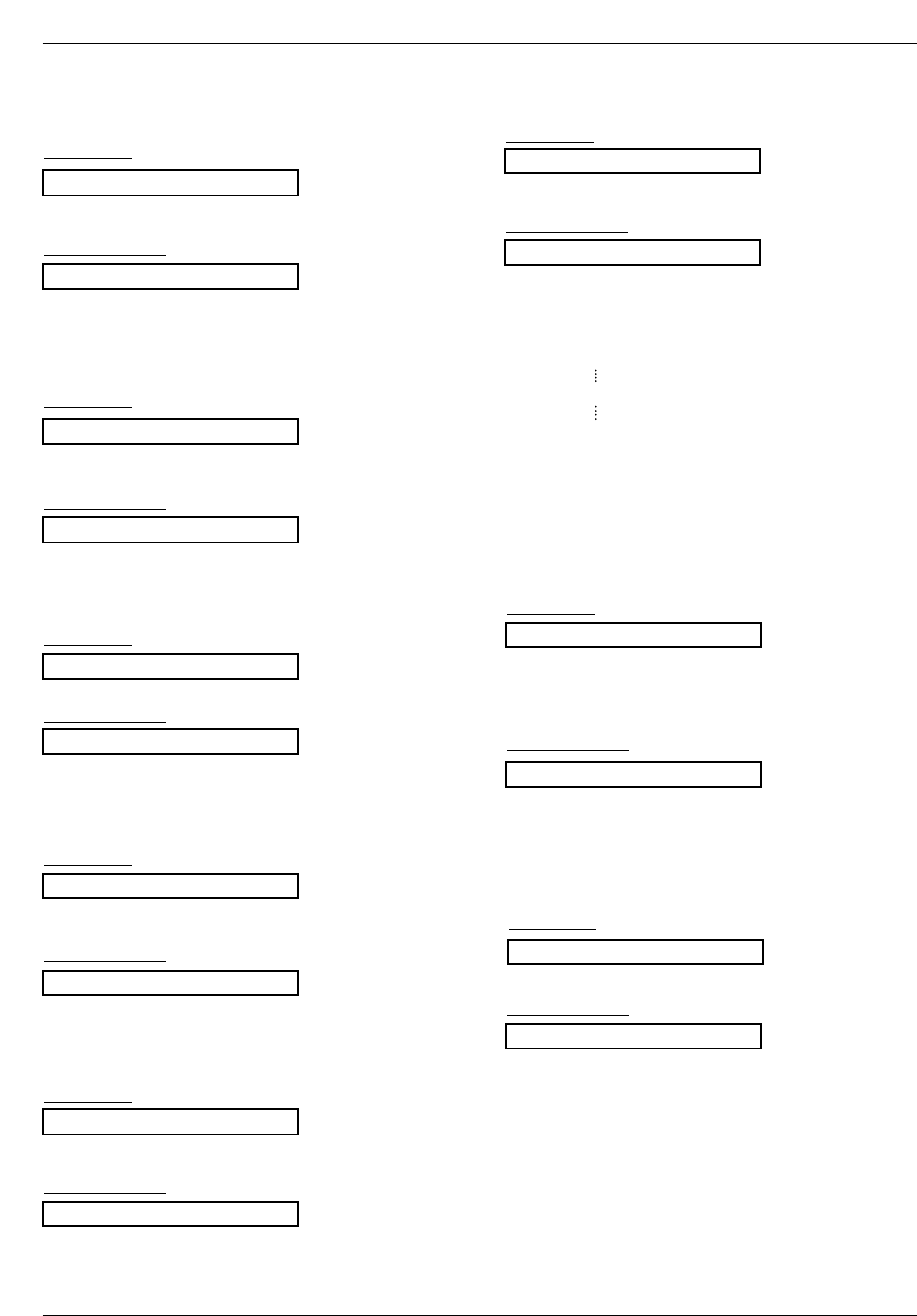
34 Plasma TV
External Control Device Setup
21. Red Adjustment (Command2:v)
GTo adjust red in color temperature.
Transmission
Data Min: 0 ~ Max: 3C
•Refer to ‘Real data mapping 3’as shown right.
[k][v][ ][Set ID][ ][Data][Cr]
Acknowledgement
[v][ ][Set ID][ ][OK][Data][x]
22. Green Adjustment (Command2:w)
GTo adjust green in color temperature.
Transmission
Data Min: 0 ~ Max: 3C
•Refer to ‘Real data mapping 3’as shown right.
[k][w][ ][Set ID][ ][Data][Cr]
Acknowledgement
[w][ ][Set ID][ ][OK][Data][x]
23. Blue Adjustment (Command2:$)
GTo adjust blue in color temperature.
Transmission
Data Min: 0 ~ Max: 3C
•Refer to ‘Real data mapping 3’as shown below.
[k][$][ ][Set ID][ ][Data][Cr]
Acknowledgement
[$][ ][Set ID][ ][OK][Data][x]
20. Color Temperature (Command2:u)
GTo adjust color temperature.
You can also adjust ACC in the Picture menu.
Transmission
Data 0: Cool 1: Normal 2: Warm 3: Off
[k][u][ ][Set ID][ ][Data][Cr]
Acknowledgement
[u][ ][Set ID][ ][OK][Data][x]
19. Balance (Command2:t)
GTo adjust balance.
You can also adjust balance in the Sound menu.
Transmission
Data Min: 0 ~ Max: 64
•Refer to ‘Real data mapping 1’. See page 32.
[k][t][ ][Set ID][ ][Data][Cr]
Acknowledgement
[t][ ][Set ID][ ][OK][Data][x]
18. Bass (Command2:s)
GTo adjust bass.
You can also adjust bass in the Sound menu.
Transmission
Data Min: 0 ~ Max: 64
•Refer to ‘Real data mapping 1’. See page 32.
[k][s][ ][Set ID][ ][Data][Cr]
Acknowledgement
[s][ ][Set ID][ ][OK][Data][x]
24. PIP Input Select (Command2:y)
G To select input source for sub picture in PIP mode.
Transmission
Data 0 : TV
1 : Video 1
2 : Video 2
3 : Component 1
4 : Component 2
5 : RGB
6 : DVI
[k][y][ ][Set ID][ ][Data][Cr]
Acknowledgement
[y][ ][Set ID][ ][OK][Data][x]
25. Abnormal State (Command2:z)
GTo recognize an abnormal state.
Transmission
Data 0: Normal (Power on and signal exist)
1: No signal (Power on).
2: Turn the monitor off with remote control.
3: Turn the monitor off with Sleep Time function.
4: Turn the monitor off with RS-232C function.
5: 5V down.
6: AC down.
7: Turn the monitor off with Fan Alarm function.
8: Turn the monitor off with Off Time function.
9: Turn the monitor off with Auto Off function.
a: Turn the monitor off with On Time function.
Data FF:Read
[k][z][ ][Set ID][ ][FF][Cr]
Acknowledgement
[z][ ][Set ID][ ][OK][Data][x]
* Real data mapping 3
0 : -30
1 : -29
2 : -28
1E : 0
3A : +28
3B : +29
3C : +30

Owner’s Manual 35
External Control Device Setup
26. ISM Method (Command2:p)
GTo avoid having a fixed image remain on screen.
Transmission
Data 0: Normal
1: White wash 2: Orbiter
3: Inversion
[j][p][ ][Set ID][ ][Data][Cr]
Acknowledgement
[p][ ][Set ID][ ][OK][Data][x]
27. Low Power (Command2:q)
GTo control the low power function on/off.
Transmission
Data 0: Low power off
1: Low power on
[j][q][ ][Set ID][ ][Data][Cr]
Acknowledgement
[q][ ][Set ID][ ][OK][Data][x]
28. Orbiter Time Setting (Command2:r)
GTo adjust orbiter operation time term.
Transmission
Data Min: 1 ~ Max: FE
[j][r][ ][Set ID][ ][Data][Cr]
Acknowledgement
[r][ ][Set ID][ ][OK][Data][x]
29. Orbiter Pixel Setting (Command2:s)
GTo adjust pixel number in orbiter function.
Transmission
Data Min: 1 ~ Max: 9
[j][s][ ][Set ID][ ][Data][Cr]
Acknowledgement
[s][ ][Set ID][ ][OK][Data][x]
30. Picture Size Setting for Double Window
mode (Command2:t)
GTo adjust main window size in Double Window mode.
Transmission
Data Min: 0 ~ Max: 14
•Refer to ‘Real data mapping1’. See page 32.
[j][t][ ][Set ID][ ][Data][Cr]
Acknowledgement
[t][ ][Set ID][ ][OK][Data][x]
31. Auto Configure (Command2:u)
GTo adjust picture position and minimize image shaking
automatically. It works only in RGB (PC) mode.
Transmission
Data 1: To set
[j][u][ ][Set ID][ ][Data][Cr]
Acknowledgement
[u][ ][Set ID][ ][OK][Data][x]
32. Tune command (Command: m a)
GTune channel to following physical number
Transmission
Data 0: Air: 02 ~ 45, Cable: 01, 0E ~ 7D
1: 0
2: 0
3: High → Main Channel: 0, Sub Channel: 1
Low →Air: 0, CATV: 1
[m][a][ ][Set ID][ ][Data0][ ][Data1][ ][Data2][ ][Data3][Cr]
Acknowledgement
[a][ ][Set ID][ ][OK][Data0][ ][Data1][ ][Data2][ ][Data3][x]
33. Channel Add/Del (Command: m b)
GTo add and delete the channels
Transmission
Data 0: Channel Memory
1: Channel Erase
[m][b][ ][Set ID][ ][Data][Cr]
[b][ ][Set ID][ ][OK][Data][x]
Acknowledgement
34. Key (Command: m c)
GTo send IR remote key code
Transmission
Data Key code: Refer to page 40.
[m][c][ ][Set ID][ ][Data][ ][Cr]
[c][ ][Set ID][ ][OK][Data][x]
Acknowledgement
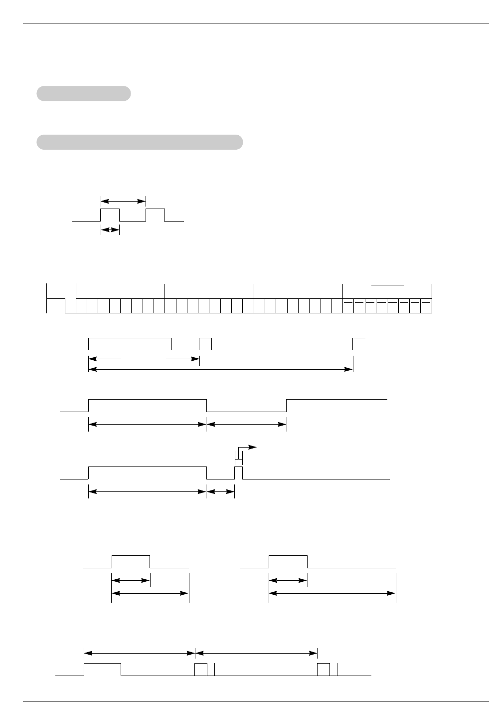
36 Plasma TV
IR Codes
G Connect your wired remote control to the Remote Control port on the Monitor.
G Output waveform
Single pulse, modulated with 37.917KHz signal at 455KHz
G Configuration of frame
G Repeat code
G Lead code
• 1st frame
Low
custom code
Lead
code High
custom code Data code Data code
TC
Tf
T1
C0
Carrier frequency
FCAR = 1/TC= fOSC/12
Duty ratio = T1/TC= 1/3
• Repeat frame
C1 C2 C3 C4 C5 C6 C7 C0 C1 C2 C3 C4 C5 C6 C7 D0 D1 D2 D3 D4 D5 D6 D7 D0 D1 D2 D3 D4 D5 D6 D7
Repeat code
9 ms 4.5 ms
0.55 ms
9 ms
2.25 ms
G Bit description
G Frame interval : Tf
The waveform is transmitted as long as a key is depressed.
• Bit “0”
Tf Tf
Tf=108ms @455KHz
0.56 ms 0.56 ms
1.12 ms
• Bit “1”
2.24 ms
How to Connect
How to Connect
Remote Control IR Code
Remote Control IR Code
IR Codes
IR Codes

Owner’s Manual 37
IR Codes
Code (Hexa) Function Note
00H
01H
02H
03H
08H
C4H
C5H
09H
10H
11H
12H
13H
14H
15H
16H
17H
18H
19H
0BH
98H
D6H
5AH
D0H
BFH
D4H
C6H
D5H
0EH
43H
44H
4DH
52H
60H
61H
63H
64H
62H
71H
72H
7BH
79H
76H
77H
AFH
1EH
1AH
54H
55H
0AH
39H
99H
R/C Button
R/C Button
R/C Button
R/C Button
R/C Button (Power On/Off)
Discrete IR Code (Only Power On)
Discrete IR Code (Only Power Off)
R/C Button
R/C Button
R/C Button
R/C Button
R/C Button
R/C Button
R/C Button
R/C Button
R/C Button
R/C Button
R/C Button
R/C Button
R/C Button
Discrete IR Code (Input TV Selection)
Discrete IR Code (Input VIDEO1 Selection)
Discrete IR Code (Input VIDEO2 Selection)
Discrete IR Code (Input COMPONENT1 Selection)
Discrete IR Code (Input COMPONENT2 Selection)
Discrete IR Code (Input DVI Selection)
Discrete IR Code (Input RGB Selection)
R/C Button
R/C Button
R/C Button
R/C Button
R/C Button
R/C Button
R/C Button
R/C Button
R/C Button
R/C Button
R/C Button
R/C Button
R/C Button
R/C Button
Discrete IR Code (Only 4:3 mode)
Discrete IR Code (Only 16:9 mode)
Discrete IR Code (Only Zoom mode)
R/C Button
R/C Button
R/C Button
R/C Button
R/C Button
R/C Button
Discrete IR Code
CH (D)
CH (E)
VOL (G)
VOL (F)
POWER
POWER ON
POWER OFF
MUTE
Number Key 0
Number Key 1
Number Key 2
Number Key 3
Number Key 4
Number Key 5
Number Key 6
Number Key 7
Number Key 8
Number Key 9
TV/VIDEO
MULTIMEDIA
TV
VIDEO1
VIDEO2
COMPONENT1
COMPONENT2
DVI
RGB
SLEEP
MENU
ENTER
APC
DASP
PIP/DW
PIP INPUT
SWAP
WIN.SIZE
POSITION
PIP CH+
PIP CH-
SPLIT ZOOM
ARC
ARC (4:3)
ARC (16:9)
ARC (Zoom)
FCR
REVIEW
AUTO PROGRAM
MEMORY/ERASE
MTS
CAPTION
AUTO CONFIG
38 Plasma TV
Troubleshooting Checklist
No output from one of
the speakers •Adjust Balance in the Sound menu. (Refer to p.20)
Unusual sound from
inside the TV
•A change in ambient humidity or temperature may result in an unusual noise
when the plasma display is turned on or off and does not indicate a fault with
the TV.
No picture &
No sound
•Check whether the TV is turned on.
•Is the power cord inserted into wall power outlet?
•Test the wall power outlet, plug another product’s power cord into the outlet
where the TV’s power cord was plugged in.
No or poor color
or poor picture
•Select Color in the Picture menu and press the VOLUME (G) button.
(Refer to p.18)
•Keep a sufficient distance between the TV and the VCR.
•Activate any function to restore the brightness of the picture.
(If still picture is on the screen for more than 5 minutes, the screen gets dark.)
The remote control
doesn’t work
•Check to see if there is any object between the TV and the remote control
causing obstruction.
•Are batteries installed with correct polarity (+ to +, - to -)?
(Refer to p.9)
•Correct remote operating mode set: TV, VCR etc.?
•Install new batteries. (Refer to p.8)
Picture OK &
No sound
•Press the VOLUME (G) button.
•Sound muted? Press MUTE button.
Picture appears slowly
after switching on
•This is normal, the image is muted during the TV startup process. Please
contact your service center, if the picture has not appeared after five minutes.
Horizontal/vertical bars
or picture shaking •Check for local interference such as an electrical appliance or power tool.
T
Troubleshooting Checklist
roubleshooting Checklist

Owner’s Manual 39
Specification
Product Specifications
Product Specifications
•The specifications shown above may be changed without notice for quality improvement.
MODELS RP-42PX10/10H/20/20H
48.4 / 1210
27.6 / 701
11.4 / 290
66 / 22.9
852 x 480 (Dot)
AC100-240V, 50/60Hz
NTSC
VHF 2 ~ 13, UHF 14 ~ 69, CATV 1 ~ 125
75 Ω
16,770,000 (256 steps of each R, G and B)
32 ~ 104°F (0 ~ 40°C)
Less than 80%
RP-50PX10/10H/20/20H
56 / 1400
30.4 / 761.5
11.4 / 290
66 / 29.9
1366 x 768 (Dot)
Width (inches / mm)
Height (inches / mm)
Depth (inches / mm)
Weight (pounds / kg)
Resolution
Power requirement
Television System
Program Coverage
External Antenna Impedance
Color
Operating Temperature Range
Operating Humidity Range