LG Electronics USA TU50PY22 Plasma Display Panel User Manual 528Aen TU 50PY22 1
LG Electronics USA Plasma Display Panel 528Aen TU 50PY22 1
Contents
- 1. User Manual Part 1
- 2. User Manual Part 2
User Manual Part 1

Please read this manual carefully and completely before
operating your TV.
Retain this manual for future reference.
Record model number and serial number of the TV in the
spaces provided below.
See the label attached on the back cover and relate this
information to your dealer if you require service.
Model Number :
Serial Number :
MODELS: 50PY2DR
50PY2DR-UA
60PY2DR
60PY2DR-UA
50PX4DR
50PX4DR-UA
LG Electronics U.S.A., Inc.
TM
R
TruSurround XT
PLASMA TV
OWNER’S MANUAL
2 Plasma TV
Warning/Caution
WARNING/CAUTION:
TO REDUCE THE RISK OF ELECTRIC SHOCK DO NOT REMOVE COVER (OR BACK). NO USER
SERVICEABLE PARTS INSIDE. REFER TO QUALIFIED SERVICE PERSONNEL.
The lightning flash with arrowhead symbol, within an equilateral triangle, is intended to alert the user to
the presence of uninsulated “dangerous voltage” within the product’s enclosure that may be of suffi-
cient magnitude to constitute a risk of electric shock to persons.
The exclamation point within an equilateral triangle is intended to alert the user to the presence of
important operating and maintenance (servicing) instructions in the literature accompanying the appli-
ance.
WARNING/CAUTION:
TO PREVENT FIRE OR SHOCK HAZARDS, DO NOT EXPOSE THIS PRODUCT TO RAIN OR MOISTURE.
FCC NOTICE
• A Class B digital device
This equipment has been tested and found to comply with the limits for a Class B digital device, pursuant to Part
15 of the FCC Rules. These limits are designed to provide reasonable protection against harmful interference in
a residential installation. This equipment generates, uses and can radiate radio frequency energy and, if not
installed and used in accordance with the instructions, may cause harmful interference to radio communications.
However, there is no guarantee that interference will not occur in a particular installation. If this equipment does
cause harmful interference to radio or television reception, which can be determined by turning the equipment off
and on, the user is encouraged to try to correct the interference by one or more of the following measures:
- Reorient or relocate the receiving antenna.
- Increase the separation between the equipment and receiver.
- Connect the equipment into an outlet on a circuit different from that to which the receiver is connected.
- Consult the dealer or an experienced radio/TV technician for help.
• Any changes or modifications not expressly approved by the party responsible for compli-
ance could void the user’s authority to operate the equipment.
CAUTION:
Do not attempt to modify this product in any way without written authorization from LG Electronics. Unauthorized mod-
ification could void the user’s authority to operate this product.
COMPLIANCE:
The responsible party for this product’s compliance is:
LG Electronics U.S.A., Inc
1000 Sylvan Avenue, Englewood Cliffs, NJ 07632
1-800-243-0000
http://www.lgusa.com
WARNING
RISK OF ELECTRIC SHOCK
DO NOT OPEN
/CAUTION
WARNING/CAUTION
TO REDUCE THE RISK OF FIRE AND ELECTRIC SHOCK, DO NOT EXPOSE THIS PRODUCT TO
RAIN OR MOISTURE.
W
Warning/Caution
arning/Caution

Owner’s Manual 3
TV Guide On Screen Notices for U.S.A.
TV Guide On Screen Notices for U.S.A.
Digital Cable Compatibility
Digital Cable Compatibility
This digital television is capable of receiving basic analog, digital basic and digital premium cable television programming by
direct connection to a cable system providing such programming. A security card provided by your cable operator is required
to view encrypted digital programming. Certain advanced interactive digital cable services such as video-on-demand, cable
operator enhanced program (For example, electronic program guide provided by the cable operator), and data enhanced
television service may require the use of a set top box. For more information contact your local cable operator.
In the United States, TV GUIDE and other related marks are registered marks of Gemstar-TV Guide International, Inc. and/or
one of its affiliates. In Canada, TV GUIDE is a registered mark of Transcontinental Inc., and is used under license by
Gemstar-TV Guide International, Inc.
The TV Guide On Screen system is protected by one or more of the following issued United States patents 6,498,895,
6,418,556, 6,331,877; 6,239,794; 6,154,203; 5,940,073; 4,908,713; 4,751,578; 4,706,121.
The TV Guide On Screen system is manufactured under license from Gemstar-TV Guide International, Inc. and/or one of its
affiliates.
Use of the CableCARDTM TradeMark.
“CableCARDTM is a trademark of Cable Television Laboratories, Inc.”
Trademark Notice
Aux Etats Unis TV GUIDE et d’autres marques relatives sont des marques déposées de Gemstar-TV Guide International,
Inc. et/ou d’une de ses sociétés affiliées. Au Canada TV GUIDE est une marque déposée de Transcontinental Inc., utilisée
sous licence de Gemstar-TV Guide International, Inc.
Le système TV Guide On Screen est fabriqués sous licence de Gemstar-TV Guide International, Inc. et/ou d’une de ses sociétés
affiliées.
Le système TV Guide On Screen est protégés par un ou plusieurs brevets émis aux Etats Unis, comme le 6,498,895,
6,418,556, 6,331,877; 6,239,794; 6,154,203; 5,940,073; 4,908,713; 4,751,578; 4,706,121.
License Notice
Patent Notice

4 Plasma TV
Warning/Caution
IMPORTANT SAFETY INSTRUCTIONS
Important safety instructions shall be provided with each apparatus. This information shall be given in a separate booklet
or sheet, or be located before any operating instructions in an instruction for installation for use and supplied with the appa-
ratus.
This information shall be given in a language acceptable to the country where the apparatus is intended to be used.
The important safety instructions shall be entitled “Important Safety Instructions”. The following safety instructions shall be
included where applicable, and, when used, shall be verbatim as follows. Additional safety information may be included by
adding statements after the end of the following safety instruction list. At the manufacturer’s option, a picture or drawing that
illustrates the intent of a specific safety instruction may be placed immediately adjacent to that safety instruction :
1. Read these instructions.
2. Keep these instructions.
3. Heed all warnings.
4. Follow all instructions.
5. Do not use this apparatus near water.
6. Clean only with dry cloth.
7. Do not block any ventilation openings. Install in accordance with the manufacturer’s instructions.
8. Do not install near any heat sources such as radiators, heat registers, stoves, or other apparatus (including ampli-
fiers)that produce heat.
9. Do not defeat the safety purpose of the polarized or grounding-type plug. A polarized plug has two blades with
one wider than the other. A grounding type plug has two blades and a third grounding prong, The wide blade or the
third prong are provided for your safety. If the provided plug does not fit into your outlet, consult an electrician for
replacement of the obsolete outlet.
10. Protect the power cord from being walked on or pinched particularly at plugs, convenience receptacles, and the
point where they exit from the apparatus.
11. Only use attachments/accessories specified by the manufacturer.
12. Use only with the cart, stand, tripod, bracket, or table specified by the manufacturer, or sold with the apparatus.
When a cart is used, use caution when moving the cart/apparatus combination to avoid injury from tip-over.
Safety Instructions
Safety Instructions
PORTABLE CART WARNING

Owner’s Manual 5
Safety Instructions
13. Unplug this apparatus during lightning storms or when unused for long periods of time.
14. Refer all servicing to qualified service personnel. Servicing is required when the apparatus has been damaged
in any way, such as power-supply cord or plug is damaged, liquid has been spilled or objects have fallen into
the apparatus, the apparatus has exposed to rain or moisture, does not operate normally, or has been dropped.
15. CAUTION concerning the Power Cord :
Most appliances recommend they be placed upon a dedicated circuit; that
is, a single outlet circuit which powers only that appliance and has no
additional outlets or branch circuits. Check the specification page of
this owner's manual to be certain.
Do not overload wall outlets. Overloaded wall outlets, loose or damaged
wall outlets, extension cords, frayed power cords, or damaged or
cracked wire insulation are dangerous. Any of these conditions could
result in electric shock or fire. Periodically examine the cord of your
appliance, and if its appearance indicates damage or deterioration,
unplug it, discontinue use of the appliance, and have the cord replaced
with an exact replacement part by an authorized servicer.
Protect the power cord from physical or mechanical abuse, such as being
twisted, kinked, pinched, closed in a door, or walked upon. Pay
particular attention to plugs, wall outlets, and the point where the
cord exits the appliance.
16. Outdoor Use Marking :
WARNING - To Reduce The Risk Of Fire Or Electric Shock, Do Not Expose This Appliance To Rain Or Moisture.
17. Wet Location Marking :
Apparatus shall not be exposed to dripping or splashing and no objects filled with liquids, such as vases, shall
be placed on the apparatus.

6 Plasma TV
Contents
After reading this manual, keep it handy for future reference.
Warning/Caution . . . . . . . . . . . . . . . . . . . . . . . . . . . . . . . .2
Digital Cable Compatibility . . . . . . . . . . . . . . . . . . . . . . . . .3
Safety Instructions . . . . . . . . . . . . . . . . . . . . . . . . . . . . .4~5
Introduction
Controls/Connection Options . . . . . . . . . . . . .8~11
Remote Control Key Functions . . . . . . . . . . 12~13
Installation
Accessories . . . . . . . . . . . . . . . . . . . . . . . . . . . . .14
Installation Instructions . . . . . . . . . . . . . . . . . .14~18
Joining the TV assembly to the wall to protect the set tum-
bling . . . . . . . . . . . . . . . . . . . . . . . . . . . . . . . . .14
Install the RING SPACER with the bolts on the set ..
as shown . . . . . . . . . . . . . . . . . . . . . . . . . . . . .15
Remove or Attache the Plate Cover . . . . . . . . . . .17
Swivel function . . . . . . . . . . . . . . . . . . . . . . . . .18
Arrangement wires . . . . . . . . . . . . . . . . . . . . . .18
External Equipment Connections . . . . . . . . . .19~25
Antenna or Cable Connection . . . . . . . . . . .19~20
VCR Setup . . . . . . . . . . . . . . . . . . . . . . . . . . .20
External A/V Source Setup . . . . . . . . . . . . . . . .21
DVD Setup . . . . . . . . . . . . . . . . . . . . . . . . . . . .21
CableCARDTM Setup . . . . . . . . . . . . . . . . . . . . .22
HDSTB Setup . . . . . . . . . . . . . . . . . . . . . . . . .22
PC Setup . . . . . . . . . . . . . . . . . . . . . . . . . .23~24
Monitor Out Setup . . . . . . . . . . . . . . . . . . . . . .25
Digital Audio Output . . . . . . . . . . . . . . . . . . . . .25
HDMI . . . . . . . . . . . . . . . . . . . . . . . . . . . . . . .26~28
TV Guide On Screen Setup . . . . . . . . . . . . . .29~35
Operation
Turning the TV On . . . . . . . . . . . . . . . . . . . . . . . .36
HOME Menu . . . . . . . . . . . . . . . . . . . . . . . . . . . .37
TV Setup . . . . . . . . . . . . . . . . . . . . . . . . . . . .38~56
On-screen Menus Language Selection . . . . . . .38
Setup Menu Options
EZ Scan (Channel Search) . . . . . . . . . . . . . . . .39
Manual Scan . . . . . . . . . . . . . . . . . . . . . . . . . .39
Channel Edit . . . . . . . . . . . . . . . . . . . . . . . . . . .40
DTV Signal Strength . . . . . . . . . . . . . . . . . . . . .40
Channel Label Setup . . . . . . . . . . . . . . . . . . . .41
Main Picture Source Selection . . . . . . . . . . . . .41
Input Label . . . . . . . . . . . . . . . . . . . . . . . . . . . .41
Video Menu Options
EZ Picture . . . . . . . . . . . . . . . . . . . . . . . . . . . .42
Manual Picture Control (Custom Option) . . . . . .42
Color Temperature Control . . . . . . . . . . . . . . . .42
Video Reset . . . . . . . . . . . . . . . . . . . . . . . . . . .42
Audio Menu Options
Audio Language . . . . . . . . . . . . . . . . . . . . . . . .43
EZ SoundRite / EZ Sound . . . . . . . . . . . . . . . . .43
Manual Sound Control (custom Option) . . . . . . .44
Front Surround . . . . . . . . . . . . . . . . . . . . . . . . .44
TV Speakers On/Off Setup . . . . . . . . . . . . . . . .45
Stereo/SAP Broadcasts Setup . . . . . . . . . . . . .45
BBE . . . . . . . . . . . . . . . . . . . . . . . . . . . . . . . . .45
Time Menu Options
Auto Clock Setup . . . . . . . . . . . . . . . . . . . . . . .46
Manual Clock Setup . . . . . . . . . . . . . . . . . . . . .46
On/Off Timer Setup . . . . . . . . . . . . . . . . . . . . .46
Sleep Timer / Auto Off . . . . . . . . . . . . . . . . . . . .47
Option Menu Features
Advanced . . . . . . . . . . . . . . . . . . . . . . . . . . . . .48
Cinema 3:2 Mode Setup . . . . . . . . . . . . . . . .48
Low Power . . . . . . . . . . . . . . . . . . . . . . . . . .48
LG Logo . . . . . . . . . . . . . . . . . . . . . . . . . . . .49
Aspect Ratio Control . . . . . . . . . . . . . . . . . . . . .50
Caption . . . . . . . . . . . . . . . . . . . . . . . . . . . . . . .51
Caption / Text . . . . . . . . . . . . . . . . . . . . . . . . . .51
Caption Option . . . . . . . . . . . . . . . . . . . . . . . .52
ISM Method . . . . . . . . . . . . . . . . . . . . . . . . . . .53
Front Display . . . . . . . . . . . . . . . . . . . . . . . . . .53
Auto Demo . . . . . . . . . . . . . . . . . . . . . . . . . . . .54
Lock Menu Options
Parental Lock Setup . . . . . . . . . . . . . . . . . . . . .56
Recorded TV . . . . . . . . . . . . . . . . . . . . . . .57~61
Notes on Memory Card . . . . . . . . . . . . . . . .62~75
Photo List . . . . . . . . . . . . . . . . . . . . . . . . . .62~67
Music List . . . . . . . . . . . . . . . . . . . . . . . . . .68~70
Timeshift . . . . . . . . . . . . . . . . . . . . . . . . . . .71~72
Recording . . . . . . . . . . . . . . . . . . . . . . . . . .73~75
TV Guide On ScreenTM System . . . . . . . . . . .76~96
IEEE 1394 . . . . . . . . . . . . . . . . . . . . . . . . . .97~108
CableCARDTM Function
Cable menu options . . . . . . . . . . . . . . . . . . . .109
Scrambled channel . . . . . . . . . . . . . . . . . . . . .109
Cable Channel List . . . . . . . . . . . . . . . . . . . . .110
Emergency Alert Message . . . . . . . . . . . . . . . .110
Remote Control
PIP (Picture-in-Picture)/Twin Picture
Watching PIP/POP/Twin Picture . . . . . . . . . . ..111
Selecting an Input Signal Source for PIP/Twin Picture
.111
Swapping PIP/Twin Picture . . . . . . . . . . . . . . .111
TV Program Selection for PIP . . . . . . . . . . . . .111
Moving the PIP sub picture . . . . . . . . . . . . . . .112
Adjusting Main and Sub Picture Sizes for Twin Picture .112
POP (Picture-out-of-Picture: Channel Scan) . .112
APM. . . . . . . . . . . . . . . . . . . . . . . . . . . . . . . . . .113
Bried Info. . . . . . . . . . . . . . . . . . . . . . . . . . . . . . .114
EZ Mute . . . . . . . . . . . . . . . . . . . . . . . . . . . . . . .115
Screen Setup for PC mode . . . . . . . . . . . . . . . . .116
External Control Device Setup . . . . . . . . . . . . . .117~122
IR Codes . . . . . . . . . . . . . . . . . . . . . . . . . . . . . .123~124
Programming the Remote . . . . . . . . . . . . . . . . . . . . .125
Programming Codes . . . . . . . . . . . . . . . . . . . . .126~127
Troubleshooting Checklist . . . . . . . . . . . . . . . . . . . . .128
Maintenance . . . . . . . . . . . . . . . . . . . . . . . . . . . . . . . .129
Product Specifications . . . . . . . . . . . . . . . . . . . . . . . .130
Warranty . . . . . . . . . . . . . . . . . . . . . . . . . . . . . . .131~132
Contents
Contents

Owner’s Manual 7
Introduction
Introduction
Introduction
What is a Plasma Display Panel (PDP)?
A plasma display panel is the latest display technology and the best way to achieve flat panel displays with excellent image quality
and large screen sizes that are easily viewable. The PDP can be thought of as a descendant of the neon lamp and it can be also
be viewed as a series of fluorescent lamps.
How does it work?
PDP is an array of cells, known as pixels, which are comprised of 3 sub pixels, corresponding to the colors red, green, and blue.
Gas in a plasma state is used to react with phosphors in each sub-pixel to produce colored light (red, green, or blue). These phos-
phors are the same types used in Cathode Ray Tube (CRT) devices such as televisions and common computer monitors.
You get the rich, dynamic colors that you expect. Each sub-pixel is individually controlled by advanced electronics to produce over
16 million different colors. All of these mean that you get perfect images that are easily viewable in a display that is less than 5
inches thick.
160° - Wide angle range of vision
Your flat panel plasma screen offers an exceptionally broad viewing angle -- over 160 degrees. This means that the display is
clear and visible to viewers anywhere in the room who can see the screen.
Wide Screen
The screen of the Plasma Display is so wide that your viewing experience is as if you are in a theater.
Multimedia
Connect your plasma display to a PC and you can use it for conferencing, games, and Internet browsing. The Picture-in-Picture
feature allows you to view your PC and video images simultaneously.
Versatile
The light weight and thin size makes it easy to install your plasma display in a variety of locations where conventional TVs will not
fit.
The PDP Manufacturing Process: a few minute colored dots may be present on the PDP screen
The PDP (Plasma Display Panel), which is the display device of this product, is composed of 0.9 to 2.2 million cells. A few cell
defects will normally occur in the PDP manufacturing process. Several tiny, minute colored dots visible on the screen should be
acceptable. This also occurs in other PDP manufacturers' products. The tiny dots appearing does not mean that this PDP is defec-
tive. Thus a few cell defects are not sufficient cause for the PDP to be exchanged or returned. Our production technology mini-
mizes these cell defects during the manufacture and operation of this product.
Cooling Fan Noise
In the same way that a fan is used in a PC computer to keep the CPU (Central Processing Unit) cool, the PDP is equipped with
cooling fans to cool the Monitor and improve its reliability. Therefore, a certain level of noise could occur while the fans are operat-
ing and cooling the PDP.
The fan noise doesn't have any negative effect on the PDP's efficiency or reliability. The noise from these fans is normal during the
operation of this product. We hope you understand that a certain level of noise from the cooling fans is acceptable and is not suffi-
cient cause for the PDP to be exchanged or returned.
8 Plasma TV
Introduction
W
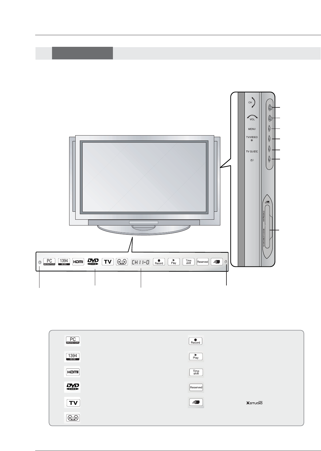
WThis is a front panel of 50PY2DR, 60PY2DR series TVs.
- This is a simplified representation of front panel.
Here shown may be somewhat different from your TV.
- This manual explains the features available on the 50PY2DR, 60PY2DR series TVs.
Front Panel Controls
Front Panel Controls
MENU Button
TV/VIDEO Button
POWER Button
VOLUME Buttons
CHANNEL
Buttons
INDEX
Switches
LED Display
on or off.
TV GUIDE Button
Remote Control
Sensor
Power Standby Indicator
When the TV is turned on, blinks orange in standby mode, blinks
green. And after orange stop blinking, you can directly turn on the TV.
But in case of green, screen is displayed in 3~4 seconds later.
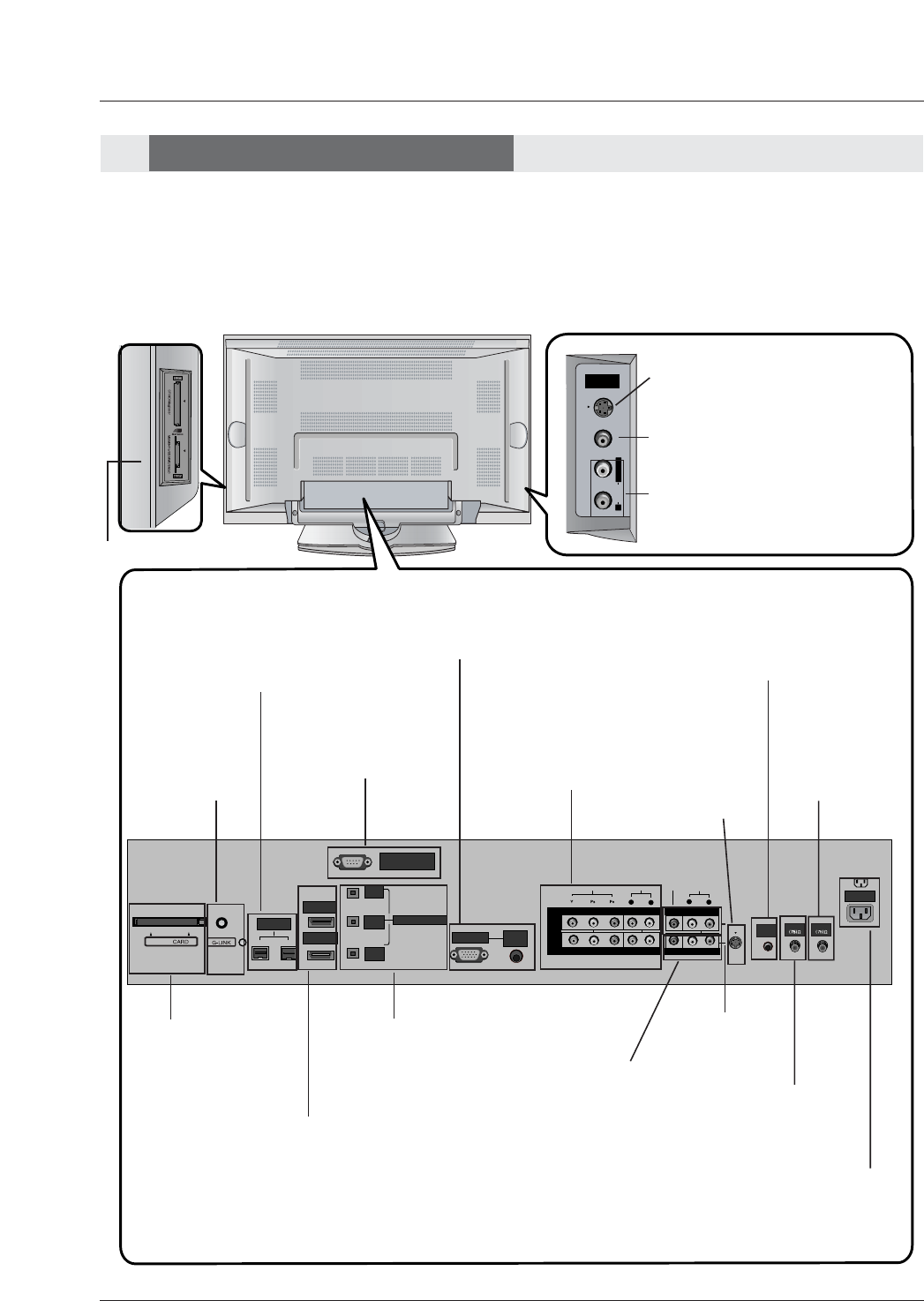
Controls
Controls
Memory Card
Slots 1,2
Programme
Display
RGB-PC(or RGB-DTV) mode
IEEE1394 mode
HDMI1/DVI or HDMI2 mode
Component1 or 2 mode
Antenna or Cable mode
Video or Front Video mode
On recording
On playing
On operating the TimeShift
On setting the reserve record
On operating the mode
RS-232C INPUT
(CONTROL/SERVICE)
AUDIO INPUT
COMPONENT
2
R
L
DIGITAL AUDIO
(OPTICAL)
DVI
INPUT
COMPONENT2
INPUT
OUTPUT
AUDIO INPUT
RGB INPUT
VIDEO INPUT
I
E
E
E
1
3
9
4
HDMI 2
HDMI /DVI
COMPONENT
1
MONITOR
OUTPUT
A/V
INPUT1
VIDEO
R
L
AUDIO
(MONO)
V
I
D
E
O
S
R
E
M
O
T
E
C
O
N
T
R
O
L
CABLE
ANTENNA
AC INPUT
DVD
/DTV
INPUT
R
S-VIDEOVIDEO
L / MONO
AUDIO
FRONT
A/V INPUT
R
RS-232C INPUT
(CONTROL/SERVICE)
AUDIO
R
L
DIGITAL AUDIO
(OPTICAL)
DVI
INPUT
COMPONENT2
INPUT
OUTPUT
AUDIO
INPUT
RGB INPUT
VIDEO
HDMI 2
HDMI /DVI
COMPONENT INPUT 1
R
L
(MONO)
CABLE
ANTENNA
AC INPUT
DVD
/DTV
INPUT
IEEE-1394
COMPONENT INPUT 2
MONITOR OUTPUT
A/V INPUT 1
VIDEO
AUDIO
S-VIDEO
REMOTE
CONTROL
Cable
Owner’s Manual 9
Introduction
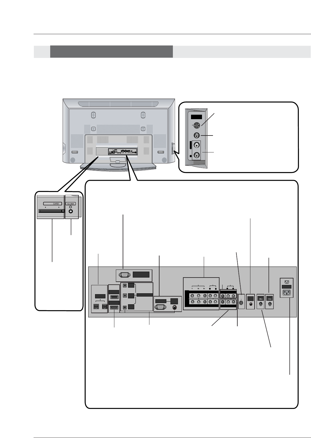
Back Connection Panel
Back Connection Panel
Antenna Input
Connect antenna
signals to the TV.
RGB/AUDIO
INPUT
Connect the moni-
tor output connec-
tor from a PC to
the appropriate
input port.
Digital Audio (DVI:
Digital Visual
Interface/Compon
ent2) Input/
Digital Audio
Output
Connect digital
audio from various
types of equipment.
Note: In standby
mode,
these ports will not
work.
DVD/DTV Input
(Component 1-2)
Connect a com-
ponent
video/audio
device to these
jacks.
Monitor Output
Connect a second
TV or Monitor.
Remote Control Port
Connect your wired
remote control here.
S-Video
Input
Connect S-
Video out from
an S-VIDEO
device.
CABLE Input
Connect cable signals to the TV,
either directly or through your
cable box.
RS-232C INPUT
(CONTROL/SER-
VICE) PORT
Connect to the RS-
232C port on a PC.
HDMI1/DVI(VIDE
O), HDMI 2
Connect a HDMI
signal to
HDMI1/DVI or
HDMI2. Or
DVI(VIDEO) sig-
nal to HDMI1/DVI
port with DVI to
HDMI cable.
S-VIDEO Input
A connection available to provide bet-
ter picture quality than the video input.
VIDEO Input
Connects the video signal from a
video device.
AUDIO Input
Use to connect to hear stereo sound
from an external device.
Audio/Video Input
Connect audio/video
output from an exter-
nal device to these
jacks.
Power Cord Socket
This TV operates on an AC power. The voltage is
indicated on the Specifications page. Never attempt
to operate the TV on DC power.
CableCARD™
Used for
CableCARD™
received Cable
Service
Provider.
G-LINK
Connect an
IR controller
to this jack.
IEEE1394
Connect
DVHS or
MicroMV to
IEEE1394
Connector.
Connection Options
Connection Options
Note:
- After removing the cover, you can insert the CableCARD™ or connect to the G-LINK jack.
W
WThis is a back panel of 50PY2DR, 60PY2DR series TVs.
10 Plasma TV
Introduction
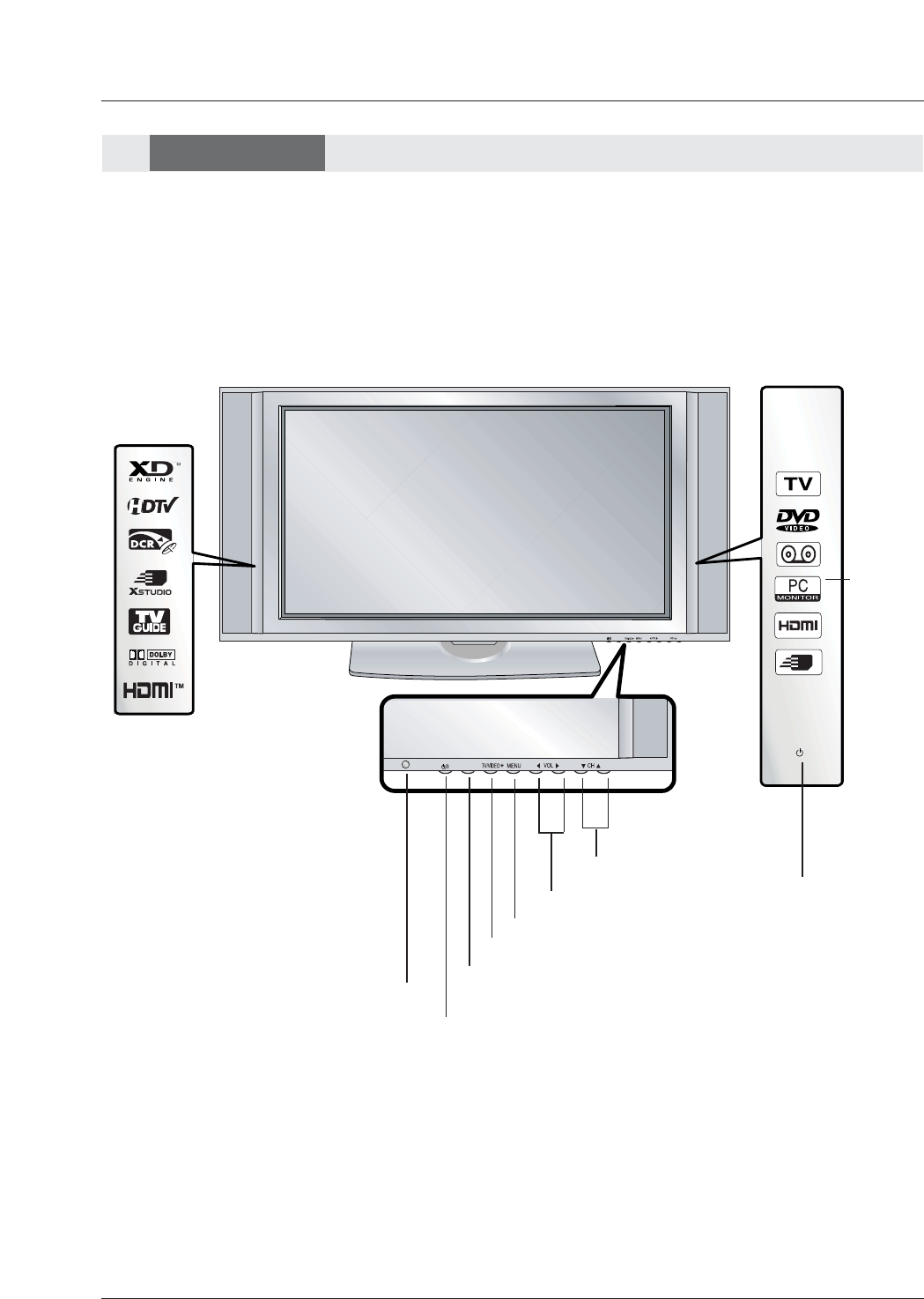
TV GUIDE
TV GUIDE
MENU Button
TV/VIDEO Button
VOLUME (FF,G) Buttons
CHANNEL (E,D) Buttons
INDEX
Switches
LED Display
on or off.
TV GUIDE Button
Remote Control
Sensor
Power Indicator
Illuminates orange in
standby mode,
Illuminates green when
the TV is turned on.
(If illuminated in red and
the power is off contact
your service center.)
POWER Button
Front Panel Controls
Front Panel Controls
W
WThis is a front panel of 50PX4DR series TVs.
- This is a simplified representation of front panel.
Here shown may be somewhat different from your TV.
Controls
Controls
Owner’s Manual 11
Introduction
Connection Options
Connection Options
W
WThis is a back panel of 50PX4DR series TVs.
RS-232C INPUT
(CONTROL/SERVICE)
AUDIO
R
L
DIGITAL AUDIO
(OPTICAL)
DVI
INPUT
COMPONENT2
INPUT
OUTPUT
AUDIO
INPUT
RGB INPUT
VIDEO
HDMI 2
HDMI1/DVI
COMPONENT INPUT 1
R
L
(MONO)
CABLE
ANTENNA
AC INPUT
DVD
/DTV
INPUT
IEEE-1394
COMPONENT INPUT 2
MONITOR OUTPUT
A/V INPUT
VIDEO
AUDIO
Cable
S-VIDEO
REMOTE
CONTROL
S-VIDEO
FRONT
A/V INPUT
VIDEO
L / MONO
AUDIO
R
S-VIDEO Input
A connection available to provide bet-
ter picture quality than the video input.
Memory Card Slots
G-LINKTM
Connect an IR
controller to this
jack.
CableCARD™
Used for
CableCARD™
received from Cable
Service Provider.
VIDEO Input
Connects the video signal from a
video device.
AUDIO Input
Use to connect to hear stereo sound
from an external device.
Antenna Inputs
Connect antenna
signals to the TV.
RGB/AUDIO INPUT
Connect the monitor output
connector from a PC to the
appropriate input port.
Digital Audio (DVI: Digital
Visual
Interface/Component2)
Input/
Digital Audio Output
Connect digital audio from
various types of equipment.
Note: In standby mode,
these ports will not work.
DVD/DTV Input
(Component 1-2)
Connect a DVHS, a
MicroMV Camcorder, or
a Set-Top Box to one of
IEEE1394 connectors.
Monitor Output
Connect a second
TV or Monitor.
Remote Control Port
Connect your wired
remote control here.
S-Video Input
Connect S-
Video out from
an S-VIDEO
device to the S-
VIDEO input.
CABLE Inputs
Connect cable signals to the
TV, either directly or through
your cable box.
RS-232C INPUT (CON-
TROL/SERVICE) PORT
Connect to the RS-232C
port on a PC.
HDMI1/DVI, HDMI 2
Connect a HDMI sig-
nal to HDMI1/DVI or
HDMI2. Or connect a
DVI(Video) signal to
HDMI1/DVI.
Audio/Video Input
Connect audio/video
output from an
external device to
these jacks.
Power Cord Socket
This TV operates on an AC power. The voltage
is indicated on the Specifications page. Never
attempt to operate the TV on DC power.
IEEE1394
Connect DVHS or
MicroMV to IEEE1394
Connector.
Back Connection Panel
Back Connection Panel
12 Plasma TV
Introduction
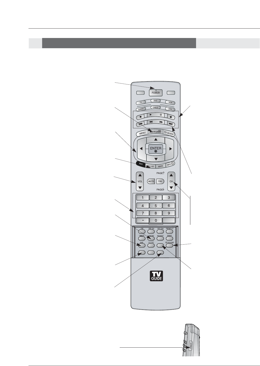
- When using the remote control, aim it at the remote control sensor on the TV.
MODE
DAY -
DAY +
FLASHBK
APM
CC
AUTO DEMO
M/C EJECT
TV INPUT TV/VIDEO
LIGHT
Illuminates the remote control
buttons.
DAY+/DAY-
Moves forward or backward in 24
hour increments in the Listings Grid.
NUMBER buttons
VCR/DVD BUTTONS
• Control some video cassette
recorders or DVD players.
("RECORD" button is not available for
DVD players.)
< Only TV mode >
•In Photo mode of Xstudio, the view
state changes to the slide show state
with “PLAY” button and the slide show
state changes to the view state with
“PAUSE” button.
• In Music mode of Xstudio, controls
the music with “PAUSE”, “STOP”,
”PLAY”, ”(Left/Right) SKIP” buttons.
Note that FF and REW do not work in
the mode.
•Control the DVHS or Camcorder of
IEEE 1394 mode.
RATIO
Changes the aspect ratio.
POWER
Turns your TV or any other programmed
equipment on or off, depending on mode.
CC
Select a closed caption:
Off, CC1~4, Text1~4.
THUMBSTICK (Up/Down/Left/Right/ENTER)
Allows you to navigate the on-screen menus
and adjust the system settings to your pref-
erence.
CHANNEL UP/DOWN
Selects available channels found with
EZ scan.
PAGE UP/PAGE DOWN
Moves from one full set of screen
information to the next one.
SAP
Selects MTS sound: Mono, Stereo, and SAP
in Analog mode. Change the audio language
in DTV mode.
EZ SOUND
Selects the sound appropriate for the
program's character.
X STUDIO
Bring up the HOME menu to the screen.
APM
Concurrently, compare with the
Daylight, Normal, Night Time
and Custom on the screen.
(Refer to p.112)
VOLUME UP/DOWN
Increases/decreases the sound level.
REC LIST
Appear the thumbnail recorded list.
M/C EJECT
When removing the Memory Card,
this button is used.
Remote Control Key Functions
Remote Control Key Functions
Owner’s Manual 13
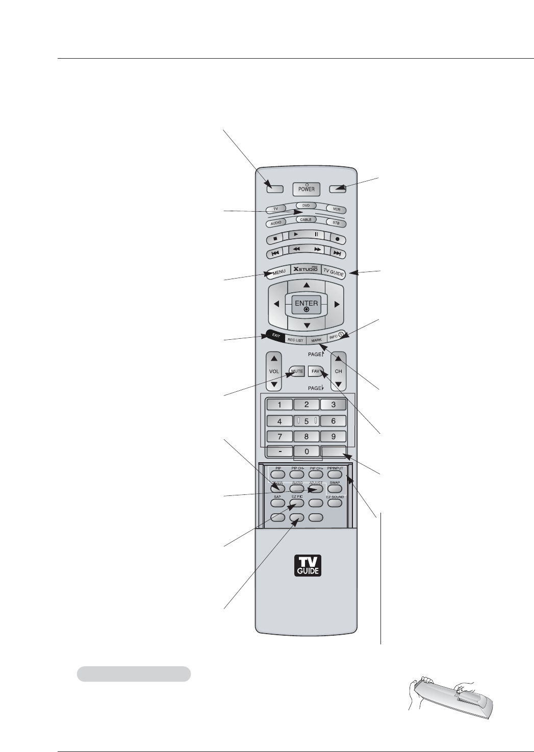
Introduction
MODE
DAY -
DAY +
FLASHBK
APM
CC
AUTO DEMO
M/C EJECT
TV INPUT TV/VIDEO
TV INPUT
When you watch the TV, Antenna and
Cable is toggled. In Video, Front Video,
Component 1-2, RGB-DTV (or RGB-PC),
HDMI1/DVI, HDMI2 and IEEE1394 input
sources, screen return to the last TV chan-
nel.
MUTE
Switches the sound on or off.
(Refer to p.114)
MODE
Selects the remote operating mode: TV,
DVD, VCR, AUDIO, CABLE or STB. Select
other operating modes, for the remote to
operate external devices.
FLASHBK
Tunes to the last channel viewed.
EXIT
Clears all on-screen displays and returns to
TV viewing from any menu.
TIMER
Lets you select the amount of time before
your TV turns itself off automatically.
MENU
Brings up the main menu to the screen.
Enters or exits a Panel Menu in the TV Guide
On Screen system.
PIP
Switches between PIP, POP (Picture-out-
of-Picture) and Twin picture modes.
Switches the video window locking or
unlocking in the Listings Grid.
PIPCH-/PIPCH+
Changes to next higher/lower PIP chan-
nel.
PIP INPUT
Selects the input source for the sub pic-
ture.
SWAP
Exchanges the main/sub images in
PIP/Twin picture mode.
EZ PIC
Adjusts the factory preset picture
depending on the viewing environment.
ADJUST
Adjusts screen position, size, and phase in
PC mode.
AUTO DEMO
Displays the slide show to explain the main
features of this TV.
TV/VIDEO
Selects: Video 1-2, Component 1-2,
RGB-DTV (or RGB-PC), HDMI1/DVI and
HDMI2 input sources.
(Only when the jack connects , Video 1-2,
Component 1-2 input sources are linked
automatically)
INFO
When you watch the TV, information dis-
plays on top of the screen. Not available
in Component 1-2, RGB, HDMI1/DVI and
HDMI2 mode.(Refer to p.113)
FAV
Scroll the Favorite channels.
TV GUIDE
Brings up the TV Guide On Screen sys-
tem to the screen.
Mark
Selects the wanted functions.
• Open the battery compartment cover on the back side and install the batteries
matching correct polarity (+ with +, - with -).
• Install two 1.5V AA batteries. Don’t mix old or used batteries with new ones.
Replace cover.
Installing Batteries
Installing Batteries
14 Plasma TV
Installation
Installation
Installation
Owner’s Manual
1.5V
1.5V
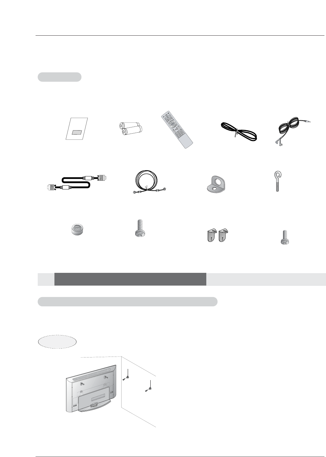
Batteries Power Cord
MODE
DAY -
DAY+
FLASHBK
AP
CC
AUTODEMO
TV INPU
75ΩRound Cable
Ensure that the following accessories are included with your plasma display. If an accessory is missing, please contact the dealer
where you purchased the product.
2-Wall brackets(60”)
2-TV brackets(60”)
G-LINK Cable
2-TV bracket bolts(60”)
Remote Control
Installation Instructions
Installation Instructions
Accessories
Accessories
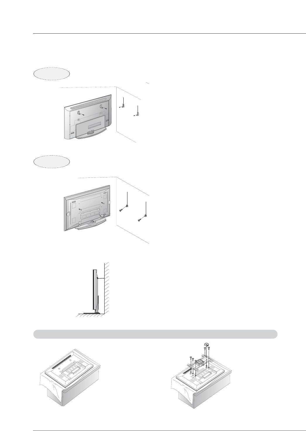
- Secure the TV assembly by joining it to a wall by using the TV/Wall brackets.
- Here shown may be somewhat different from your TV.
Joining the
Joining the TV assembly to the wall to protect the set tumbling
TV assembly to the wall to protect the set tumbling
• After the set must be mounted on the desk top, Insert
the 2 eye-bolts and tighten securely in the upper holes
as shown.
Install wall the brackets on the wall with 2 bolts*, (not
supplied with the product), as shown.
Match the height of the eye-bolts and the wall brack-
ets.
Check to be sure the eye-bolts or the brackets are
tightened securely.
6-RING SPACER
(Only 60PY2DR series )
6-Wall mounting
bracket bolts
(Only 60PY2DR series )
D-sub 15 pin Cable
2-Wall brackets(50”) 2-eye-bolts(50”)
50PY2DR
Owner’s Manual 15
Installation
• Secure the TV assembly to the wall with strong
strings or wire cables, (not supplied with the prod-
uct), as shown.
• After the set must be mounted on the desk top, install the 2 ring
spacer on the TV.
And then install the TV brackets on the ring spacer as shown.
Insert the 2 bolts and tighten securely, in the upper holes on
the brackets.
Install the wall brackets on the wall with 2 bolts*, (not sup-
plied with the product).
Match the height of the TV brackets and the wall brackets.
Check to be sure the brackets are tightened securely.
• After the set must be mounted on the desk top, Insert
the 2 eye-bolts and tighten securely in the upper holes
as shown.
Install wall the brackets on the wall with 2 bolts*, (not
supplied with the product), as shown.
Match the height of the eye-bolts and the wall brack-
ets.
Check to be sure the eye-bolts or the brackets are
tightened securely.
60PY2DR
50PX4DR
1. Put the RING SPACER
in the holes of the bolts
before connecting to
the wall mounting
bracket.
2. When you connect the
wall mounting bracket
to the set, connect to it
by using the bolts,
(supplied with the
product), as shown.
Install the RING SP
Install the RING SPACER with the bolts on the set as shown.
ACER with the bolts on the set as shown.(Only 60PY2DR series )
16 Plasma TV
Installation
Installation Instructions
Installation Instructions
GROUNDING
Ensure that you connect the grounding / earth wire to prevent possible
electric shock. If grounding methods are not possible, have a qualified
electrician install a separate circuit breaker. Do not try to ground the
unit by connecting it to telephone wires, lightening rods, or gas pipes.
Power
Supply
Short-circuit
Breaker
4 inches
4 inches
4 inches4 inches
2 inches
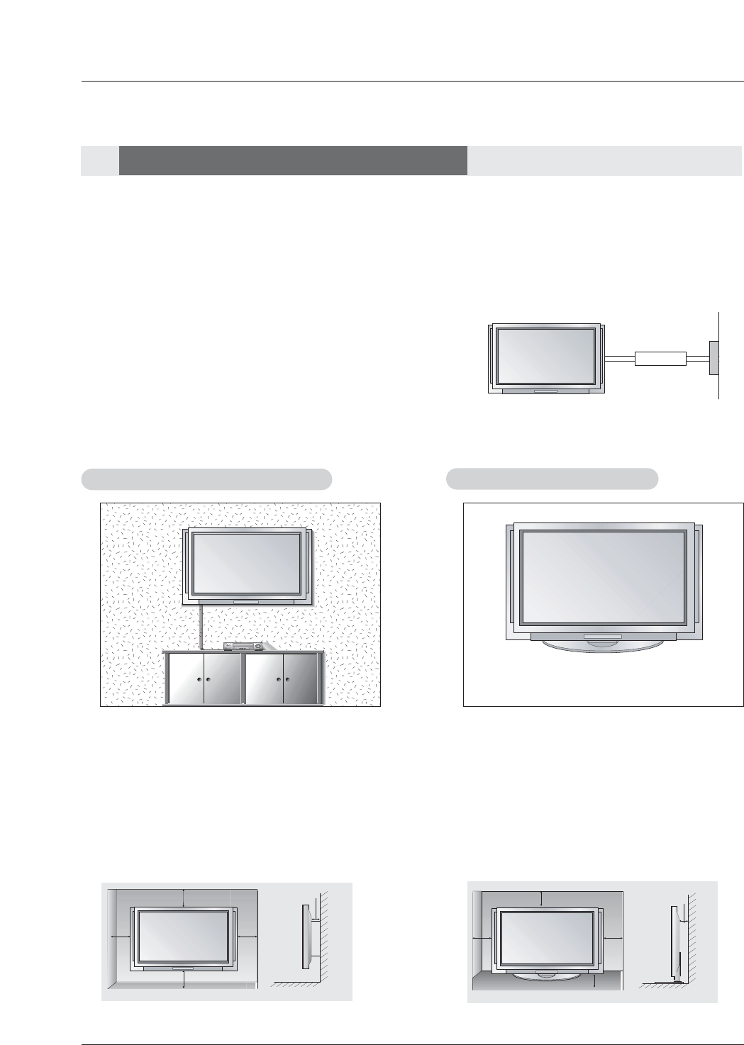
W
Wall Mount: Horizontal installation
all Mount: Horizontal installation
For proper ventilation, allow a clearance of 4” on each
side and 2” from the wall. Detailed installation instruc-
tions are available from your dealer, see the optional
Wall Mounting Bracket Installation.
4 inches
4 inches
2.36 inches
4 inches
2 inches
Desktop Pedestal Installation
Desktop Pedestal Installation
For proper ventilation, allow a clearance of 4” on each
side and the top, 2.36” on the bottom, and 2” from the
wall. Detailed installation instructions are included in
the optional Desktop Stand Installation.
• The TV can be installed in various ways such as on a wall, or on a desktop etc.
• The TV is designed to be mounted horizontally.
- This manual explains the features available on the 50PY2DR, 60PY2DR series TVs.
- Here shown may be somewhat different from your TV.
Owner’s Manual 17
Installation
RS-232C INPUT
(CONTROL/SERVICE)
AUDIO INPUT
COMPONENT
2
R
L
DIGITAL AUDIO
(OPTICAL)
DVI
INPUT
COMPONENT2
INPUT
OUTPUT
AUDIO INPUT
RGB INPUT
VIDEO INPUT
I
E
E
E
1
3
9
4
HDMI 2
HDMI /DVI
COMPONENT
1
MONITOR
OUTPUT
A/V
INPUT1
VIDEO
R
L
AUDIO
(MONO)
V
I
D
E
O
S
R
E
M
O
T
E
C
O
N
T
R
O
L
CABLE
ANTENNA
AC INPUT
DVD
/DTV
INPUT
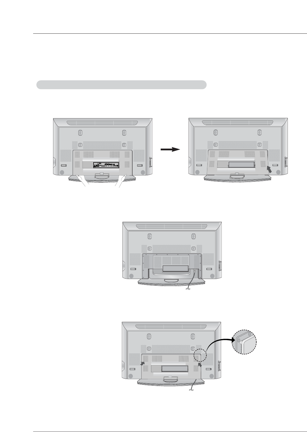
Remove or
Remove or Attache the Plate Cover
Attache the Plate Cover (Only 50/60PY2DR series )
2. Connect the power cord on the TV’s back.
- This function explains the features available on the 50PY2DR, 60PY2DR series TVs.
• When moving or connecting the power cord, be used the these methods.
• And after removing the plate cover, you must install the wall brackets on the wall.
1. With hands, push the lower left/right of plate cover and
then pull out to the front.
3. In attaching the plate cover, firstly you set projection of
the GUIDE to BUSHING RUBBER of the upper left/right.
Push and put the plate cover with hands.
18 Plasma TV
Installation
RS-232C INPUT
(CONTROL/SERVICE)
AUDIO INPUT
COMPONENT
2
R
L
DIGITAL AUDIO
(OPTICAL)
DVI
INPUT
COMPONENT2
INPUT
OUTPUT
AUDIO INPUT
RGB INPUT
VIDEO INPUT
I
E
E
E
1
3
9
4
HDMI 2
HDMI /DVI
COMPONENT
1
MONITOR
OUTPUT
A/V
INPUT1
VIDEO
R
L
AUDIO
(MONO)
V
I
D
E
O
S
R
E
M
O
T
E
C
O
N
T
R
O
L
CABLE
ANTENNA
AC INPUT
DVD
/DTV
INPUT
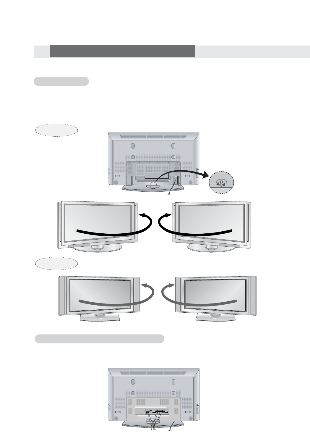
Swivel function
Swivel function
- This function explains the features available on the 50PY2DR, 60PY2DR series TVs.
• After installing the TV, you can adjust the the TV set manually to the left or right direction by 20 degrees to suit your viewing posi-
tion.
Arrangement wires
Arrangement wires (Only 50/60PY2DR series )
- This function explains the features available on the 50PY2DR, 60PY2DR series TVs.
• Run the accessory device wires inside the JACK MANAGEMENT pole as shown.
Note: Before adjusting the angle, you must loosen (to the left) the shaft bolt on the middle of stand’s back.
And when stand be level with TV, you must close (to the right) the shaft bolt to set the hole.(As shown below)
20°
Installation Instructions
Installation Instructions
50/60PY2DR
50PX4DR
20°
Owner’s Manual 19
Installation
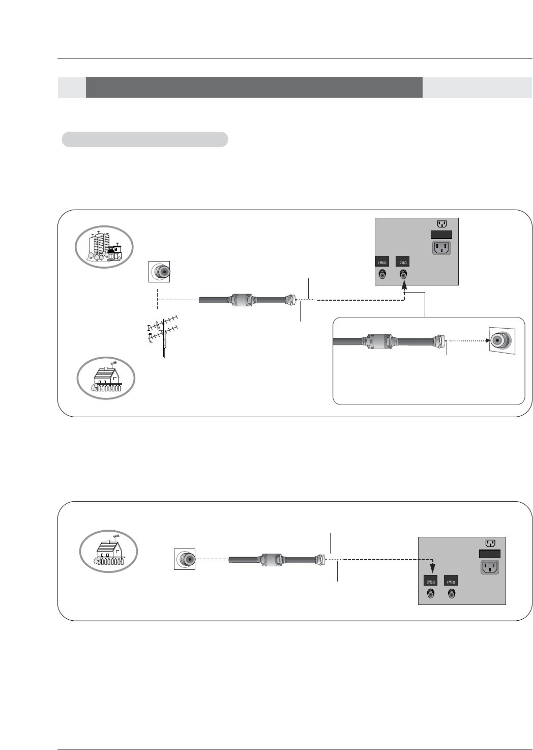
Antenna or Cable Connection
Antenna or Cable Connection
- Wall Antenna Socket or Outdoor Antenna without a Cable Box Connections
- For optimum picture quality, adjust antenna direction if needed.
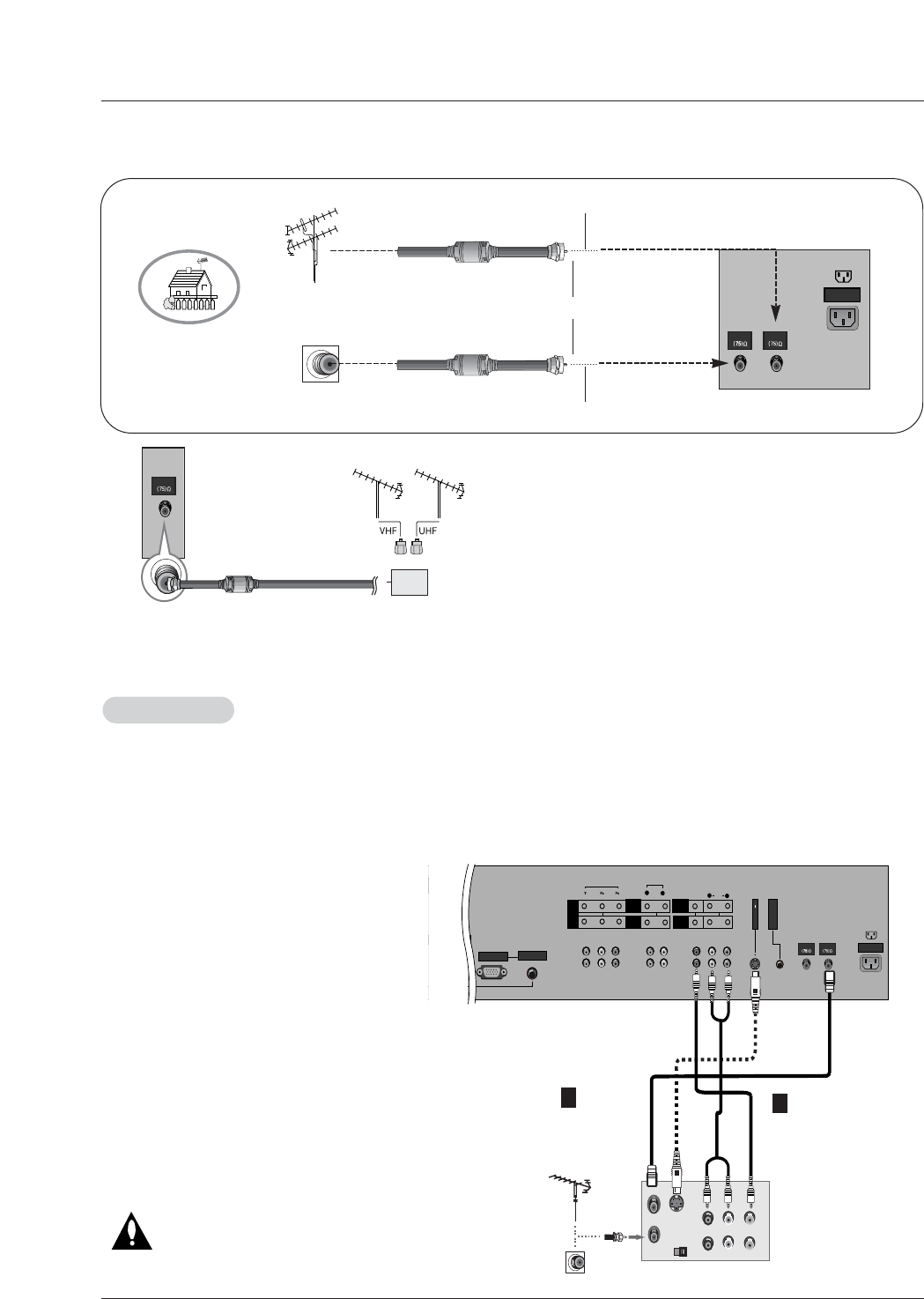
1. Analog and Digital TV signals provided on antenna
2. Analog and Digital TV signals provided on cable
CABLE
ANTENNA
AC INPUT
Multi-family Dwellings/Apartments
(Connect to wall antenna socket)
Single-family Dwellings /Houses
(Connect to wall jack for outdoor antenna)
Outdoor
Antenna
Wall Antenna
Socket
VHF Antenna
UHF Antenna
RF Coaxial Wire (75 ohm)
Bronze Wire
Turn clockwise to tighten.
Bronze Wire
Be careful not to bend the bronze wire when
connecting the antenna.
Bronze Wire
Cable TV Wall
Jack RF Coaxial Wire (75 ohm)
CABLE
ANTENNA
AC INPUT
External Equipment Connections
External Equipment Connections
Turn clockwise to tighten.
20 Plasma TV
Installation
- To avoid picture noise (interference), leave an adequate distance between the VCR and TV
- Use the ISM Method (on the Option menu) feature to avoid having a fixed image remain on the screen for a long period of
time. If the 4:3 picture format is used; the fixed images on the sides of the screen may remain visible on the screen.
Connection Option 1
Set VCR output switch to 3 or 4 and then tune
TV to the same channel number.
Connection Option 2
1. Connect the audio and video cables from the
VCR's output jacks to the TV input jacks, as
shown in the figure.
When connecting the TV to VCR, match the
jack colors (Video = yellow, Audio Left = white,
and Audio Right = red).
If you connect an S-VIDEO output from VCR
to the S-VIDEO input, the picture quality is
improved; compared to connecting a regular
VCR to the Video input.
2. Insert a video tape into the VCR and press
PLAY on the VCR. (Refer to the VCR owner’s
manual.)
3. Select the input source with using the
TV/VIDEO button on the remote control. (If
connected to A/V INPUT , select Video input
source)
Do not connect to both Video and
S-Video at the same time.
VCR Setup
VCR Setup
S-VIDEO OUT
IN
(R) AUDIO (L) VIDEO
34
OUTPUT
SWITCH
ANT OUT
ANT IN
S-232C INPUT
NTROL/SERVICE)
AUDIO INPUT
COMPONENT
2
R
L
DIGITAL AUDIO
(OPTICAL)
AUDIO INPUT
RGB INPUT
VIDEO INPUT
COMPONENT
1
MONITOR
OUTPUT
A/V
INPUT1
VIDEO
R
L
AUDIO
(MONO)
V
I
D
E
O
S
R
E
M
O
T
E
C
O
N
T
R
O
L
CABLE
ANTENNA
AC INPUT
DVD
/DTV
INPUT
VCR Rear
1
Note: The TV will let you know when the analog, cable, and digital channel scans are complete.
• In a poor signal area to improve picture quality, purchase
and install a signal amplifier.
• If the antenna needs to be split for two TV’s, install a “2-
Way Signal Splitter” in the connections.
• If the antenna is not installed properly, contact your deal-
er for assistance.
ANTENNA
Signal
Amplifier
3. Analog and Digital TV signals provided on cable and antenna
Antenna
RF Coaxial Wire (75 ohm)
Bronze Wire
Turn clockwise to tighten.
Cable TV Wall
Jack RF Coaxial Wire (75 ohm)
CABLE
ANTENNA
AC INPUT
2
Bronze Wire
Owner’s Manual 21
Installation
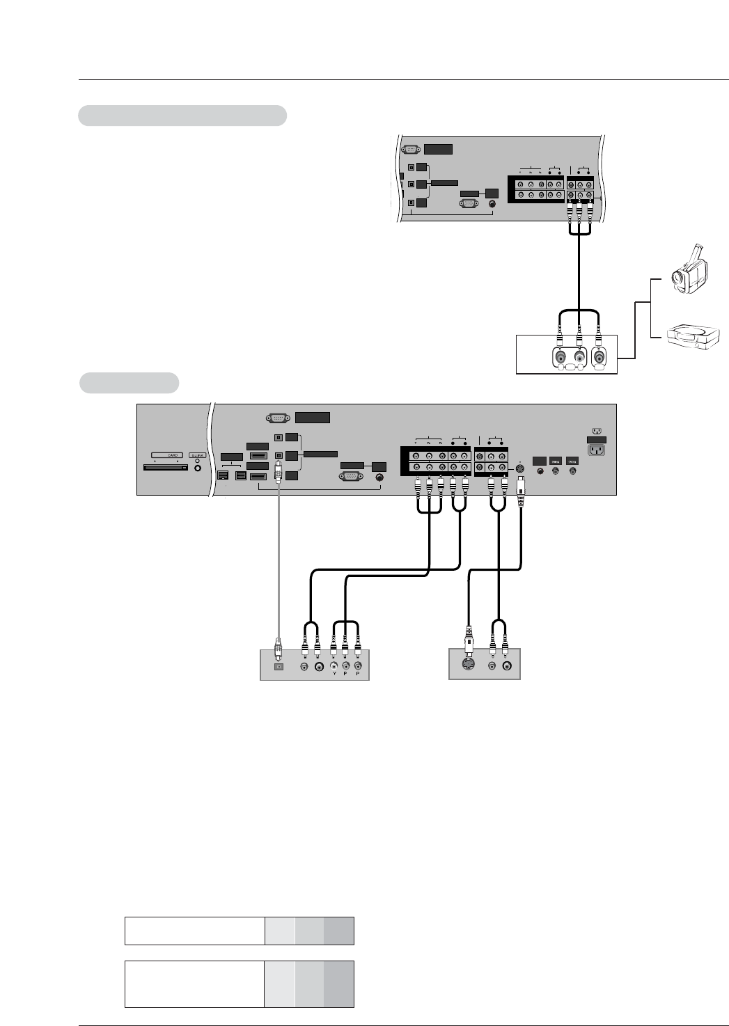
•Component Input ports
To get better picture quality, connect a DVD player to the compo-
nent input ports as shown below.
How to connect
Connect the audio and video cables from the external equip-
ment's output jacks to the TV input jacks, as shown in the
figure.
When connecting the TV to external equipment, match the
jack colors (Video = yellow, Audio Left = white, and Audio
Right = red).
How to use
1. Select the input source with using the TV/VIDEO button on
the remote control. Note that this TV finds the connected
input sources automatically for Video 1-2 and Component 1-
2. It is presumed that RGB, HDMI1/DVI and HDMI2 sources
are connected.
2. Operate the corresponding external equipment. For connec-
tion instructions for operating the TV Guide On Screen sys-
tem, see page 29.
Component ports
on the TV YPBPR
Video output ports
on DVD player
Y
Y
Y
Y
Pb
B-Y
Cb
PB
Pr
R-Y
Cr
PR
How to connect
1. Connect the DVD video outputs (Y, PB, PR) to the COMPONENT (Y, PB, PR) INPUT jacks on the TV and connect the DVD
audio outputs to the AUDIO INPUT jacks on the TV, as shown in the figure.
2. If your DVD only has an S-Video output jack, connect this to the S-VIDEO input on the TV and connect the DVD audio outputs
to the AUDIO INPUT jacks on the TV, as shown in the figure.
Note: If your DVD player does not have component video output, use S-Video.
How to use
1. Turn on the DVD player, insert a DVD.
2. Use the TV/VIDEO button on the remote control to select Component 1 or Component 2. (If connected to S-VIDEO, select
the Video or Front Video external input source.)
3. Refer to the DVD player's manual for operating instructions.
External
External A/V Source Setup
A/V Source Setup
DVD Setup
DVD Setup
RS-232C INPUT
(CONTROL/SERVICE)
AUDIO
R
L
DIGITAL AUDIO
(OPTICAL)
DVI
INPUT
COMPONENT2
INPUT
OUTPUT
RGB INPUT
VIDEO
HDMI 2
DMI /DVI
COMPONENT INPUT 1
R
L
(MONO)
V
I
D
E
O
S
R
E
M
O
T
E
C
O
N
T
R
O
L
CABLE
ANTENNA
AC INPUT
DVD
/DTV
INPUT
COMPONENT INPUT 2
MONITOR OUTPUT
A/V INPUT
VIDEO
AUDIO
RL
AUDIO VIDEO
AUDIO
INPUT
RS-232C INPUT
(CONTROL/SERVICE)
AUDIO
R
L
DIGITAL AUDIO
(OPTICAL)
DVI
INPUT
COMPONENT2
INPUT
OUTPUT
RGB INPUT
VIDEO
HDMI 2
HDMI1 /DVI
COMPONENT INPUT 1
R
L
(MONO)
CABLE
ANTENNA
AC INPUT
DVD
/DTV
INPUT
IEEE-1394
COMPONENT INPUT 2
MONITOR OUTPUT
A/V INPUT
VIDEO
AUDIO
BR
(R) AUDIO (L)
DIGITAL AUDIO
OPTICAL
(R) AUDIO (L)
S-VIDEO
AUDIO
INPUT
S-VIDEO
REMOTE
CONTROL
Cable
DVD
or
Camcorder
Video Game Set
Notes:
• Digital Audio will not work for Component 1 input source.
• Digital Audio operation has priority if Digital Audio and AUDIO L/R
are connected at the same time.
or
22 Plasma TV
Installation
- This TV can receive Digital Over-the-air/Cable signals without an external digital set-top box. However, if you do receive Digital
signals from a digital set-top box or other digital external device, refer to the figure as shown below.
- This TV supports HDCP (High-bandwidth Digital Contents Protection) protocol for Digital Contents (480p,720p,1080i).
How to connect
Use the TV’s COMPONENT (Y, PB, PR) INPUT, RGB, HDMI1/DVI
or HDMI2 jack for video connections, depending on your set-top
box connector. Then, make the corresponding audio connections.
How to use
1. Turn on the digital set-top box. (Refer to the owner’s manual for
the digital set-top box.)
2. Use TV/VIDEO on the remote control to select Component 1,
Component 2,RGB-DTV,HDMI1/DVI or HDMI2 source.
HDSTB Setup
HDSTB Setup
RS-232C INPUT
(CONTROL/SERVICE)
AUDIO
R
L
DIGITAL AUDIO
(OPTICAL)
DVI
INPUT
COMPONENT2
INPUT
OUTPUT
RGB INPUT
VIDEO
HDMI 2
HDMI1 /DVI
COMPONENT INPUT 1
R
L
(MONO)
CABLE
ANTENNA
AC INPUT
DVD
/DTV
INPUT
IEEE-1394
COMPONENT INPUT 2
MONITOR OUTPUT
A/V INPUT
VIDEO
AUDIO
(R) AUDIO (L)
RGB-DTV OUTPUT
BR
(R) AUDIO (L)
DIGITAL AUDIO
OPTICAL
(R) AUDIO (L)
DVI-DTV OUTPUT
DIGITAL AUDIO
OPTICAL
HDMI-DTV OUTPUT
AUDIO
INPUT
S-VIDEO
REMOTE
CONTROL
Digital Set-top Box
or or
Signal
480i
480p
720p
1080i
Component 1/2
Yes
Yes
Yes
Yes
RGB-DTV,HDMI1/DVI,HDMI2
No
Yes
Yes
Yes
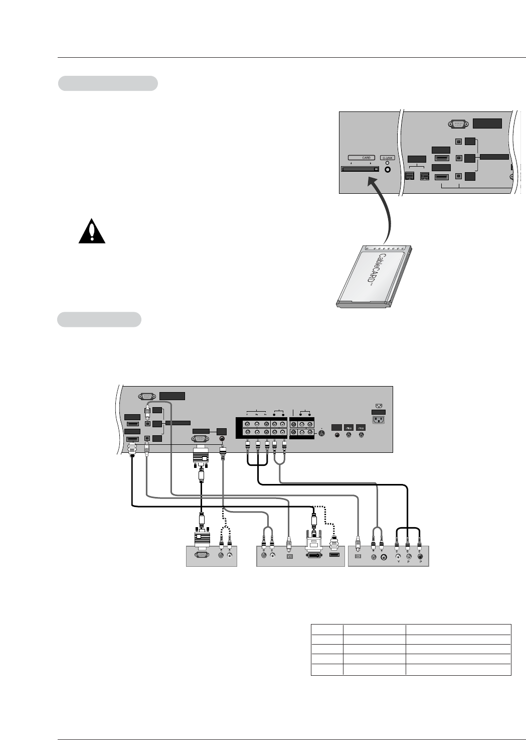
CableCARD
CableCARDTM
TM Setup
Setup
RS-232C INPUT
(CONTROL/SERVICE)
DIGITAL AUDIO
(OPTICAL)
DVI
INPUT
COMPONENT2
INPUT
OUTPUT
RGB I
HDMI 2
HDMI1 /DVI
IEEE-1394
Cable
How to use
Insert the CableCARDTM
TM received from the cable service provider to the
CableCARDTM
TM slot of TV back panel.
If the pairing information about this TV and the CableCARD is automati-
cally displayed on the screen, contact with the cable service provider by
phone.
Note :
• CableCARDTM
TM have the types of Motorola, Scientific Atlanta, SCM etc..
These 3 types of CableCARDTM
TM can be used for this PLASMA TV.
Caution: When removing the CableCARDTM
TM, do not
drop it as this may cause damage to the
CableCARDTM
TM.

Owner’s Manual 23
Installation
<When the PC supports DVI>
How to connect
1. Connect the PC to HDMI1/DVI port of this TV with an HDMI-to-DVI cable(not supplied with this product).
If you do not need to connect audio, HDMI2 port is also available for the DVI video connection.
2. If the PC(or the sound card of the PC) has a fiber optic digital audio output connector, connect the PC's audio output to DIGI-
TAL AUDIO(OPTICAL) port for DVI INPUT.
3. If the PC(or the sound card of the PC) has an analog audio output connector, connect the PC's audio output to AUDIO INPUT
port located on the right side of RGB INPUT port.
How To Use
1. To get the best picture quality, adjust the PC graphics card to 1024x768, 60Hz.
2. Select HDMI1/DVI input source in main input option of SETUP menu.(Refer to P.62)
TV/VIDEO button is also available for this purpose.
3. Check the image on your TV. There may be noise associated with the resolution, vertical pattern, contrast or brightness in PC
mode. If noise is present, change the PC output to another resolution, change the refresh rate to another rate or adjust the
brightness and contrast on the VIDEO menu until the picture is clear. If the refresh rate of the PC graphic card can not be
changed, change the PC graphic card or consult the manufacturer of the PC graphic card.
<When the PC supports RGB>
How to connect
1. Connect the PC to RGB INPUT port of this TV with a RGB cable.
2. If the PC(or the sound card of the PC) has an analog audio output connector, connect the PC's audio output to AUDIO INPUT
port located on the right side of RGB INPUT port.
How To Use
1. To get the best picture quality, adjust the PC graphics card to 1024x768, 60 Hz.
2. Select RGB-PC input source in main input option of SETUP menu.(Refer to P.41)
Once you select RGB-PC in main input option of SETUP menu, TV/VIDEO button is also available for this purpose.
3. Check the image on your TV. There may be noise associated with the resolution, vertical pattern, contrast or brightness in PC
mode. If noise is present, change the PC output to another resolution, change the refresh rate to another rate or adjust the
brightness and contrast on the VIDEO menu until the picture is clear. If the refresh rate of the PC graphic card can not be
changed, change the PC graphic card or consult the manufacturer of the PC graphic card.
PC Setup
PC Setup
- This TV provides Plug and Play capability, meaning that the PC adjusts automatically to the TV's settings.
- The TV perceives 640x480, 60Hz as DTV 480p based on the PC graphic card, change the screen scanning rate for the graphic
card accordingly.
24 Plasma TV
Installation
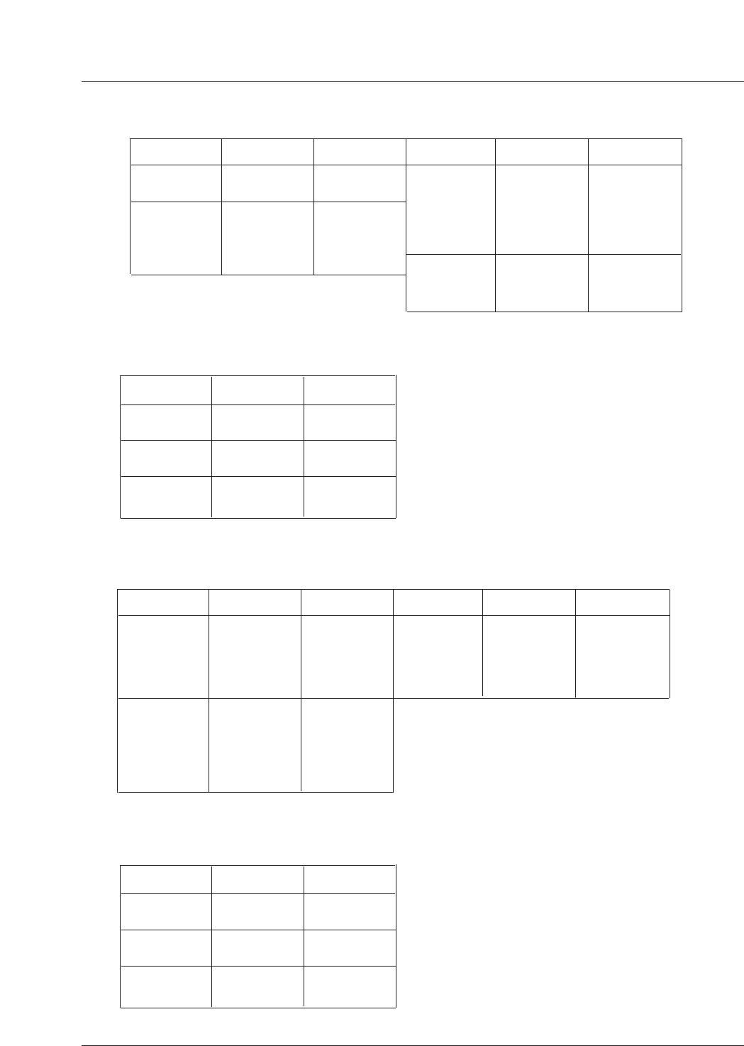
Resolution
720x400
640x480
800x600
Horizontal
Frequency(KHz)
31.469
37.927
31.469
37.861
37.500
43.269
70.08
85.03
59.94
72.80
75.00
85.00
35.156
37.879
48.077
46.875
53.674
48.363
56.476
60.023
56.25
60.31
72.18
75.00
85.06
60.00
70.06
75.02
Vertical
Frequency(Hz) Resolution Horizontal
Frequency(KHz)
Vertical
Frequency(Hz)
1024x768
Monitor Display Specifications (RGB-PC )
Resolution
720x480
1280x720
1920x1080
Horizontal
Frequency(KHz)
31.47
31.50
45.00
44.96
33.75
33.72
59.94
60
60.00
59.94
60.00
59.94
Vertical
Frequency(Hz)
Monitor Display Specifications (RGB-DTV )
Resolution
640x480
800x600
Horizontal
Frequency(KHz)
31.469
37.861
37.500
43.269
35.156
37.879
48.077
46.875
53.674
59.94
72.80
75.00
85.00
56.25
60.31
72.18
75.00
85.06
48.363
56.476
60.023
60.00
70.06
75.02
Vertical
Frequency(Hz) Resolution Horizontal
Frequency(KHz)
Vertical
Frequency(Hz)
1024x768
Monitor Display Specifications (HDMI-PC)
Resolution
720x480
1280x720
1920x1080
Horizontal
Frequency(KHz)
31.500
31.469
45.00
44.96
33.75
33.72
60
59.94
60.00
59.94
60.00
59.94
Vertical
Frequency(Hz)
Monitor Display Specifications (HDMI-DTV)
Owner’s Manual 25
Installation
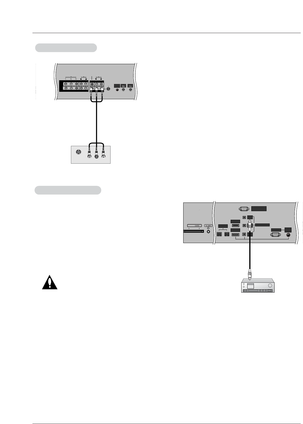
Send the TV’s audio to external audio equipment via the Digital Audio
Output (Optical) port.
How to connect
1. Connect one end of an optical cable to the TV Digital Audio
(Optical) Output port.
2. Connect the other end of the optical cable to the digital audio (opti-
cal) input on the audio equipment.
3. Set the “ TV Speaker option - Off” in the AUDIO menu. Refer to
page 45.
See the external audio equipment instruction manual for operation.
Caution: Do not look into the optical output port.
Looking at the laser beam may damage
your vision.
Digital
Digital Audio Output
Audio Output
RS-232C INPUT
(CONTROL/SERVICE)
DIGITAL AUDIO
(OPTICAL)
DVI
INPUT
COMPONENT2
INPUT
OUTPUT
RGB INPUT
HDMI 2
HDMI1 /DVI
DVD
/DTV
INPUT
IEEE-1394
AUDIO
INPUT
Cable
The TV has a special signal output capability which allows you to
hook up a second TV or monitor.
Connect the second TV or monitor to the TV’s MONITOR OUT-
PUT. See the Operating Manual of the second TV or monitor for
further details regarding that device’s input settings.
Note
• Component, RGB-PC/RGB-DTV, HDMI1/DVI and HDMI2 , DTV
input sources cannot be used for Monitor out.
AUDIO
R
L
AUDIO INPUT
RGB INPUT
VIDEO
COMPONENT INPUT 1
R
L
(MONO)
CABLE
ANTENNA
AC INPUT
DVD
/DTV
INPUT
COMPONENT INPUT 2
MONITOR OUTPUT
A/V INPUT
VIDEO
AUDIO
S-VIDEO IN
(L) AUDIO (R)
VIDEO
S-VIDEO
REMOTE
CONTROL
Monitor Out Setup
Monitor Out Setup

26 Plasma TV
Installation
- HDMITM, the HDMI logo and High-Definition Multimedia Interface are trademarks or registered trademarks of HDMI Licensing
LLC."
- This TV can receive the High-Definition Multimedia Interface(HDMI) or the Digital Visual Interface(DVI).
- This TV supports HDCP(High-bandwidth Digital Contents Protection) Protocol for 720x480p, 1280x720p, and 1920x1080i reso-
lution.
- When you connect this TV with a source device(DVD player, Set Top Box or PC) supporting Auto HDMI/DVI function, the output
resolution of the source device will be automatically set to 1280x720p.
- If the source device does not support Auto HDMI1/DVI, you need to set the output resolution appropriately.
To get the best picture quality, adjust the DVD Player or Set Top Box's output resolution to 1280x720p, and the PC graphics card's
output resolution to 1024x768, 60Hz.
- If the source device has an HDMI output, no other audio connection is necessary because HDMI-to-HDMI connection includes
both video and audio.
- If the source device has a DVI output and no HDMI output, a separated audio connection is necessary.
<When the source device (DVD player or Set Top Box) supports HDMI>
How To Connect
1. Connect the source device to HDMI1/DVI or HDMI2 port of this TV with an HDMI cable(not supplied with this product).
2. No separated audio connection is necessary.
How To Use
- If the source device supports Auto HDMI function, the output resolution of the source device will be automatically set to
1280x720p.
- If the source device does not support Auto HDMI, you need to set the output resolution appropriately.
To get the best picture quality, adjust the output resolution of the source device to 1280x720p.
- Select HDMI1/DVI or HDMI2 input source in main input option of SETUP menu.(Refer to P.41)
VIDEO button is also available for this purpose.
<When the source device(DVD player or Set Top Box) supports DVI>
How To Connect
1. Connect the source device to HDMI1/DVI port of this TV with a HDMI-to-DVI cable(not supplied with this product).
Do not use HDMI2 port for DVI connection if you want to connect audio.
2. A separated audio connection is necessary.
3. If the source device has a fiber optic digital audio output, connect the audio output to DIGITAL AUDIO(OPTICAL) port for DVI
INPUT.
4. If the source device has an analog audio output connector, connect the PC's audio output to AUDIO INPUT port located on the
right side of RGB INPUT port.
How To Use
- If the source device supports Auto DVI function, the output resolution of the source device will be automatically set to 1280x720p.
- If the source device does not support Auto DVI, you need to set the output resolution appropriately.
To get the best picture quality, adjust the output resolution of the source device to 1280x720p.
- Select HDMI1/DVI input source in main input option of SETUP menu.(Refer to P.41)
VIDEO button is also available for this purpose.
HDMI
HDMI
Owner’s Manual 27
Installation
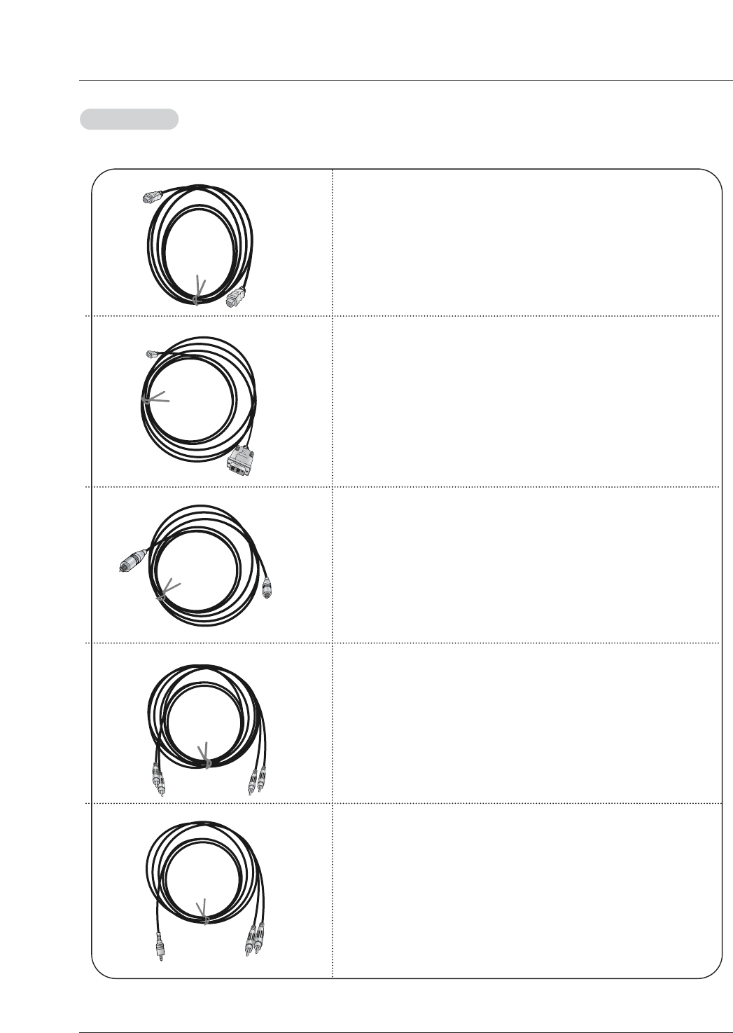
Cable sample
HDMI Cable
(not supplied with the product)
HDMI to DVI Cable
(not supplied with the product)
Fiber Optic Digital Audio Cable
(not supplied with the product)
Analog Audio Cable(RCA type)
(not supplied with the product)
Analog Audio Cable(Stereo to RCA type)
(not supplied with the product)
Reference
Reference
28 Plasma TV
Installation
How to use
1. Connect the HDMI1/DVI Source Devices(DVD Player or Set Top Box or PC) and the TV SET.
2. Turn on the display by pressing the POWER button on the TV SET and HDMI1/DVI Source Devices remote control.
3. Select HDM1/DVI Input source in Main Input option of SETUP menu.(Refer to P.41)
4. Check the image on your TV SET. There may be noise associated with the resolution, vertical pattern, contrast or brightness in
HDMI1/DVI Source Devices. If noise is present, change the HDMI1/DVI Source Devices to another resolution, change the
refresh rate or adjust the brightness and contrast on the menu until the picture is clear. If the refresh rate of the PC graphics
card can not changed, change the PC graphics card or consult the manufacturer of the PC graphics card.
Notes:
- Depending on the graphics card, DOS mode may not work if you use a HDMI1 to DVI Cable.
- Avoid keeping a fixed image on the TV SET screen for a long period of time. The fixed image may become permanently imprint-
ed on the screen. Use the Orbiter screen saver when possible.
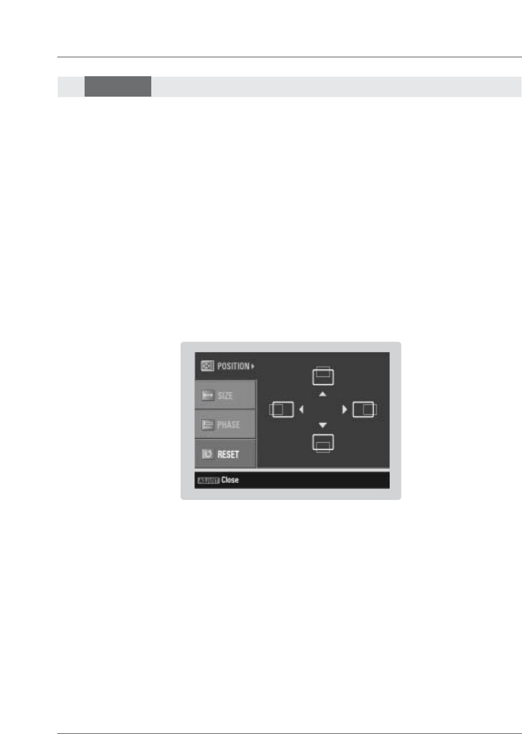
- When Source Devices connected HDMI/DVI Input, output PC Resolution(VGA, SVGA, XGA), Position, Size may not fit to
Screen. As shown the lower picture, press the ADJUST button to adjust the screen Position of TV SET and contact an PC
graphics card service center.
- When Source Devices connected HDMI1/DVI Input output TV SET Resolution(480p, 720p, 1080i), TV SET Display fit EIA/CEA-
861-B Specification to Screen. If not, refer to the Manual of HDMI1/DVI Source Devices or contact your service center.
- In case HDMI1/DVI Source Devices is not connected Cable or poor cable connection, "NO SIGNAL" OSD display in HDMI1/DVI
Input. And In case of, Video Resolution not supported TV SET output in HDMI1/DVI Source Devices, "INVALID FORMAT" OSD
display. Refer to the Manual of HDMI1/DVI Source Devices or contact your service center.
In This Mode, the Supported TV SET Resolution Specification
- 1920 x 1080 I @ 59.94Hz / 60Hz, 16:9
- 1280 x 720 P @ 59.94Hz / 60Hz, 16:9(preferred format)
- 720 x 480 P @ 59.94Hz / 60Hz, 16:9
- 720 x 480 P @ 59.94Hz / 60Hz, 4:3
In This Mode, the Supported PC Resolution Specification
- 640 x 480 @ 59.94Hz
- 640 x 480 @ 72.80Hz
- 640 x 480 @ 75Hz
- 640 x 480 @ 85Hz
- 800 x 600 @ 56.25Hz
- 800 x 600 @ 60.31Hz
- 800 x 600 @ 72.18Hz
- 800 x 600 @ 75Hz
- 800 x 600 @ 85.06Hz
- 1024 x 768 @ 60Hz(preferred format)
- 1024 x 768 @ 70.06Hz
- 1024 x 768 @ 75.02Hz
HDMI
HDMI
Owner’s Manual 29
Installation
AUDIO
R
L
VIDEO
COMPONENT INPUT 1
R
L
(MONO)
CABLE
ANTENNA
AC INPUT
DVD
/DTV
INPUT
COMPONENT INPUT 2
MONITOR OUTPUT
A/V INPUT 1
VIDEO
AUDIO
3
TV SET
TV
VCR
Cable IN
(R) AUDIO (L) VIDEO
34
OUTPUT
SWITCH
S-VIDEO
REMOTE
CONTROL
Cable
Cable Box Rear
Cable Box Front
or
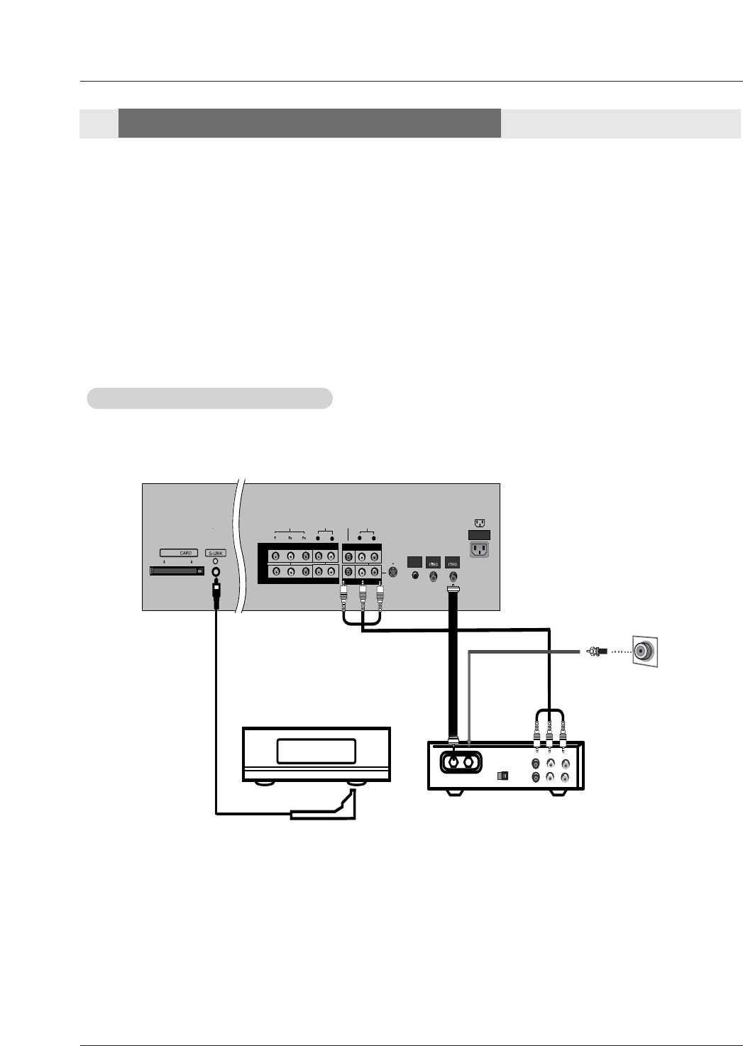
Cable Service with a Cable Box
Cable Service with a Cable Box
- The TV Guide On Screen system uses Setup information to provide you with show listings and lineups in your area—which are
updated several times a day.
- Once you set up the TV according to manufacturer’s instructions, you are ready to set up the TV Guide On Screen system.
- To download program listings the TV Guide On Screen system needs to be able to change channels on your cable box when
the TV is not in use. Please connect the supplied G-LINK cable to the G-LINK jack of the TV. After you connect the G-LINK
cable you will be able to control your cable box using the TV’s remote.
Note:The TV Guide On Screen system interactive program guide provides listings for cable-ready, cable box, and digital cable
services as well as over-the-air broadcast. It does not provide listings for satellite services.
How to connect Cable Box
TV Guide On Screen Setup
TV Guide On Screen Setup
30 Plasma TV
Installation
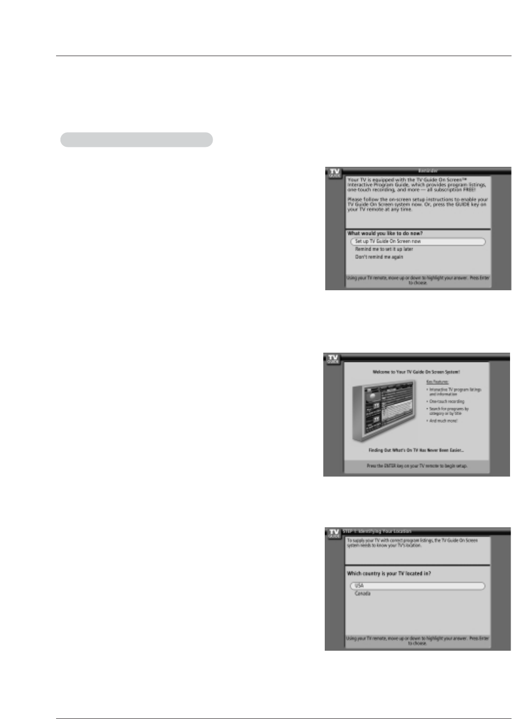
The TV Guide On Screen system's Welcome Screen appears:
-- by pressing the TV Guide key
-- when you power On your TV if you previously skipped "Set up TV
Guide On Screen now" on the Reminder Screen.
The Welcome Screen highlights features of the TV Guide On Screen
system.
Press ENTER to begin Setup.
How to use
1. Screen 1: Country
• This screen asks you the location of your TV.
• Use the D/Ebutton to highlight a country.
• Press ENTER to display Screen 2.
The TV Guide On Screen system's Reminder Screen appears:
-- after initial TV set up
-- if you power Off the TV and then power it back On
To make a selection, use the D/Ebutton to highlight to an option,
and press ENTER.
• "Set up TV Guide On Screen now," displays the Welcome Screen.
Press ENTER to begin Setup.
• "Remind me to set up later" returns you to watching TV.
• "Don't remind me again" returns you to watching TV and stops the
reminder screen from appearing upon power On.
Note:
• The G-LINKTM cable is necessary for the TV Guide On Screen system to work with your Cable Box and VCR. See Page
29 for G-LINKTM connection instructions.
2.Reminder Screen
1.Welcome Screen
TV Guide On Screen Setup
TV Guide On Screen Setup
Owner’s Manual 31
Installation
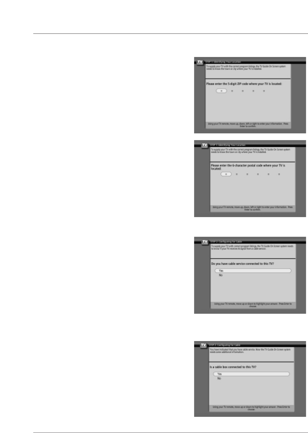
2. Screen 2: Enter Zip or Postal Code
Option 1
• If you selected USA in Screen 1, you see the ZIP Code screen.
• You input numbers by either pressing the number keys on the remote
or using the D/Ebutton to display a number, and then the F/Gbut-
ton to move to another field.
• Press ENTER to display Screen 3.
Option 2
• If you selected Canada in Screen 1, you see the Postal Code screen.
• You input characters by using the D/Ebutton, and then the F/G
button to move to another field.
• Press ENTER to display Screen 3.
3. Screen 3: Do you have Cable Service connected?
• If you select Yes, you see Screen 4.
• If you select No, you see Screen 12.
4. Screen 4: Do you have a Cable Box?
• If you select Yes, you see Screen 5.
• If you select No, you see Screen 12.
32 Plasma TV
Installation
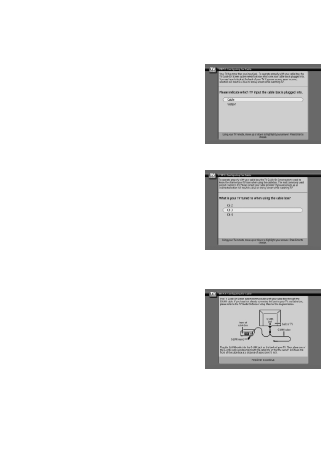
6. Screen 6: Cable Box Tuning Channel
• Select the channel used for the cable box.
• Press ENTER to display Screen 7.
7. Screen 7: Cable Box Configuration Diagram
• The diagram shows the correct way to install the G-LINK Cable from
the back of the device to the cable box.
Make sure the G-LINKTM Cable is properly installed.
• Press ENTER to display Screen 8.
5. Screen 5: Which TV input is the cable box plugged into?
• If you select Cable, you see Screen 6.
• If you make any other choice, you see Screen 7 .
Owner’s Manual 33
Installation
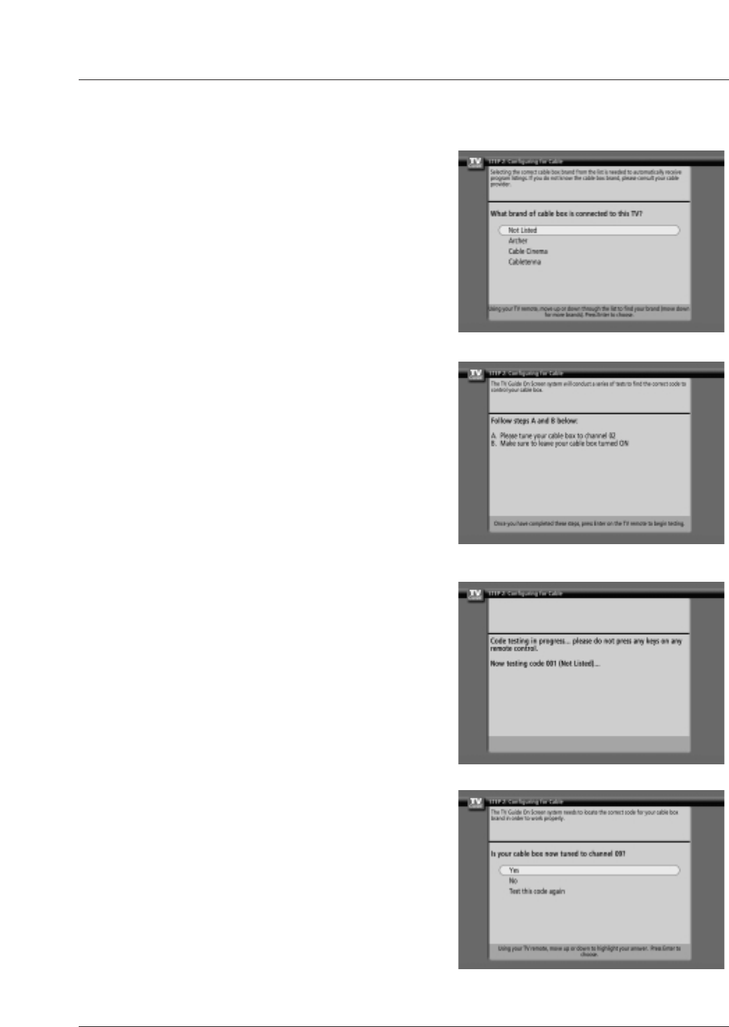
8. Screen 8: Cable Box Brand Name
• Use the D/Ebutton to select a cable box brand.
• Press ENTER to display Screen 9.
9. Screen 9: Cable Box Preparation
• Follow the on-screen instructions, and press ENTER to display
Screen 10.
10. Screen 10: Cable Box Code Testing
• When testing is done, Screen 11 displays automatically.
11. Screen 11: Cable Box Tuned to Channel 9?
• If you select Yes, you see Screen 12.
• If you select No, a different code is tested in Screen 10.
Note:
• Many Cable Boxes require testing more than one code.
• If you select Test this code again, the same code is tested again
in Screen 10.
34 Plasma TV
Installation
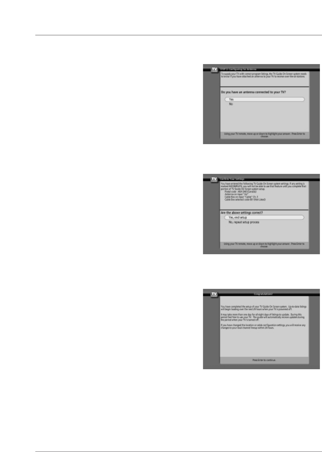
14. Screen 14: Congratulations
•Press ENTER to display Screen 15.
13. Screen 13: Are your basic settings correct?
•If you select Yes, you see Screen 14.
•If you select No, you see Screen 1.
12. Screen 12: Do you have an antenna connected?
•If you select Yes, you see Screen 13.
Note:
•If you selected No in Screen 3 then you must
select Yes in this screen to receive a channel
lineup and listings.
•If you select No, you see Screen 13.
Owner’s Manual 35
Installation
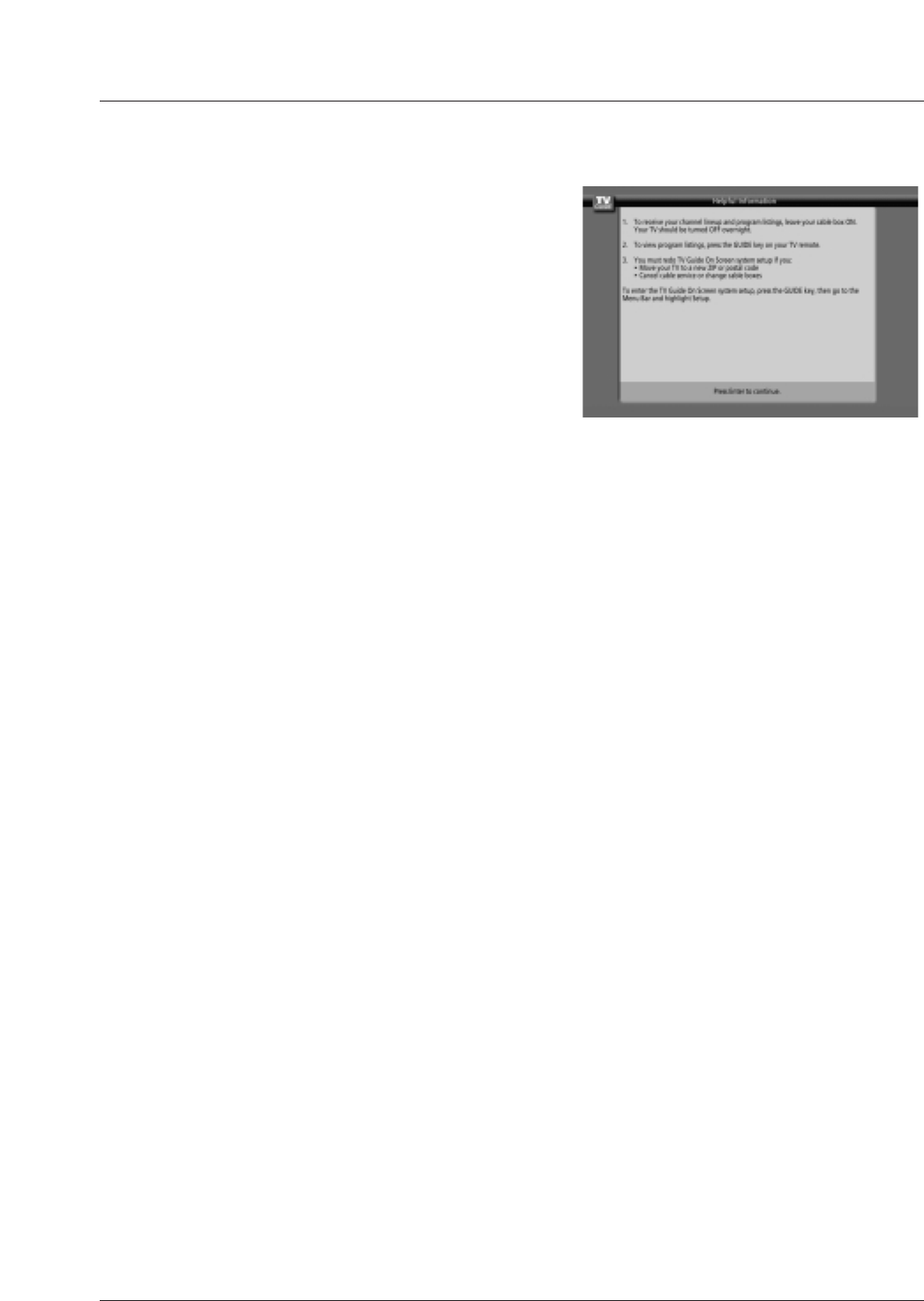
15. Screen 15: Helpful Information
•This screen tells you valuable information on using your Guide.
•Press ENTER to watch TV.
Notes:
• The TV Guide On Screen system receives program listings data through your cable or over-the-air video signal. In order to
receive regular program listings, please remember to do the following:
1. Turn OFF your TV when it is not in use. (Do not unplug the power cord.)
2. If you have a Cable box connected, leave it ON.
3. If you have more than one Cable system in your area, you may be prompted to select which Cable system’s program data to
download. If so prompted, please follow the on-screen instructions.

36 Plasma TV
Operation
1. First, connect power cord correctly. At this moment, the TV switches to standby mode.
In standby mode to turn TV on, press the power, TV/VIDEO,CH (D/E)button on the TV or press
the POWER,TV/VIDEO,TV INPUT,CH (+,-),Number (0 ~ 9) button on the TV .
Notes:
• If you intend to be away on vacation, disconnect the power plug from the wall power outlet.
• After turning on the TV, it will take up to a week for the TV Guide On Screen system to receive full
listings data.
• When the TV is turned on, blinks orange in standby mode, blinks green. And after orange stop
blinking, you can directly turn on the TV. But in case of green, screen is displayed in 3~4 seconds
later.
• If power isn’t turn on in red, contact your service center.
• When the power turns on, the screen of TV Guide is automatically showed. In case the prior condi-
tion turns on putting again after the power code puts out in conditon turning on power, the screen of
TV Guide is showed a little bit late.
2. Select the viewing source by using TV/VIDEO,TV INPUT button on the remote control.
This TV is programmed to remember which mode it was last set to, even if you turn the TV off.
3. When finished using the TV, press the POWER button on the remote control. The TV reverts to
standby mode.
Operation
Operation
T
Turning the TV On
urning the TV On
Owner’s Manual 37
Operation
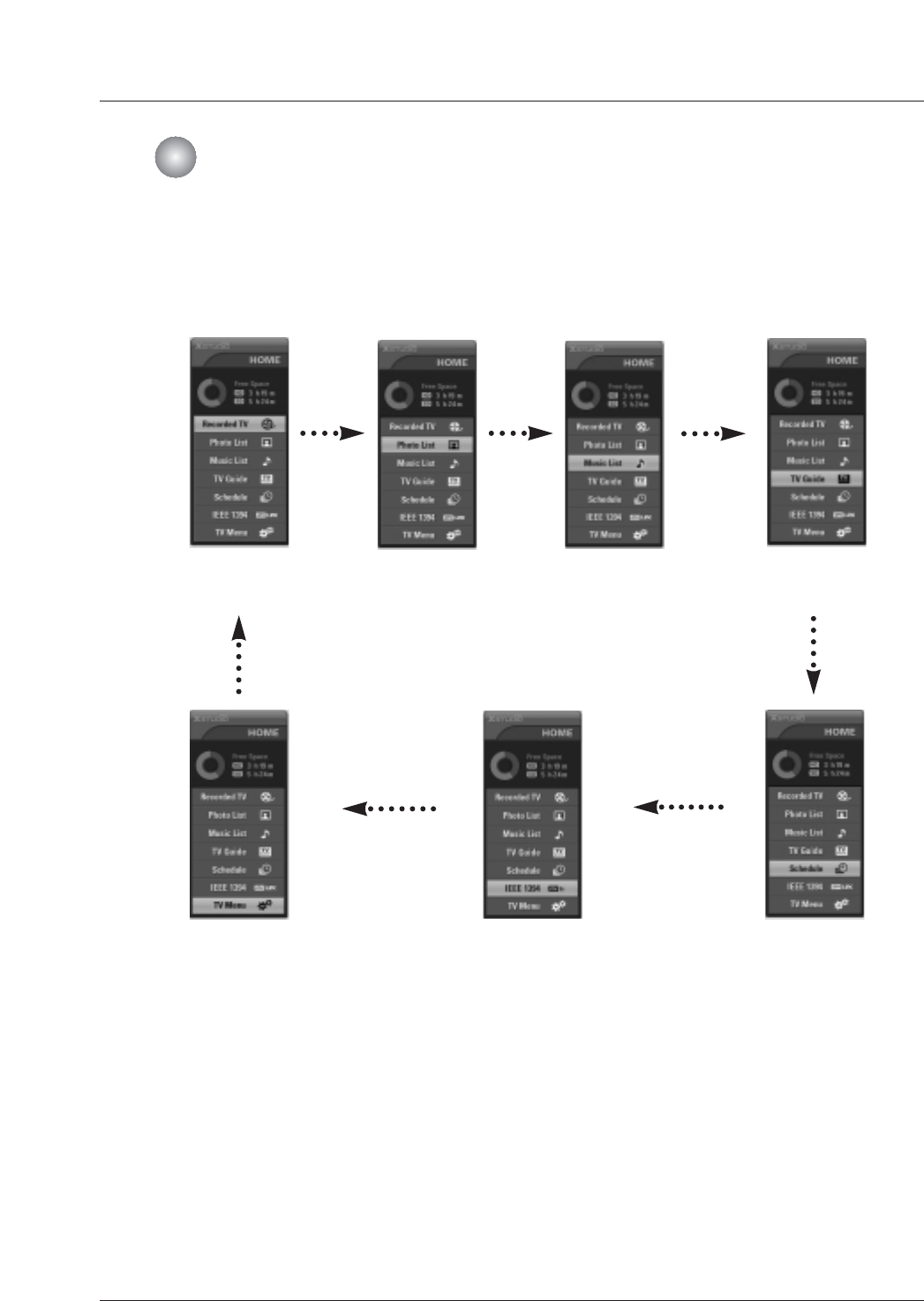
HOME Menu
HOME Menu
-This menu is a contents guide.
In HOME Menu, you enter the recorded list of DVR, photo list and music list of DVR or Memory Card, TV
Guide,Schedule of the TV Guide, IEEE1394 or TV Menu.
Recorded TV Photo List Music List TV Guide
TV Menu IEEE 1394 Schedule
38 Plasma TV
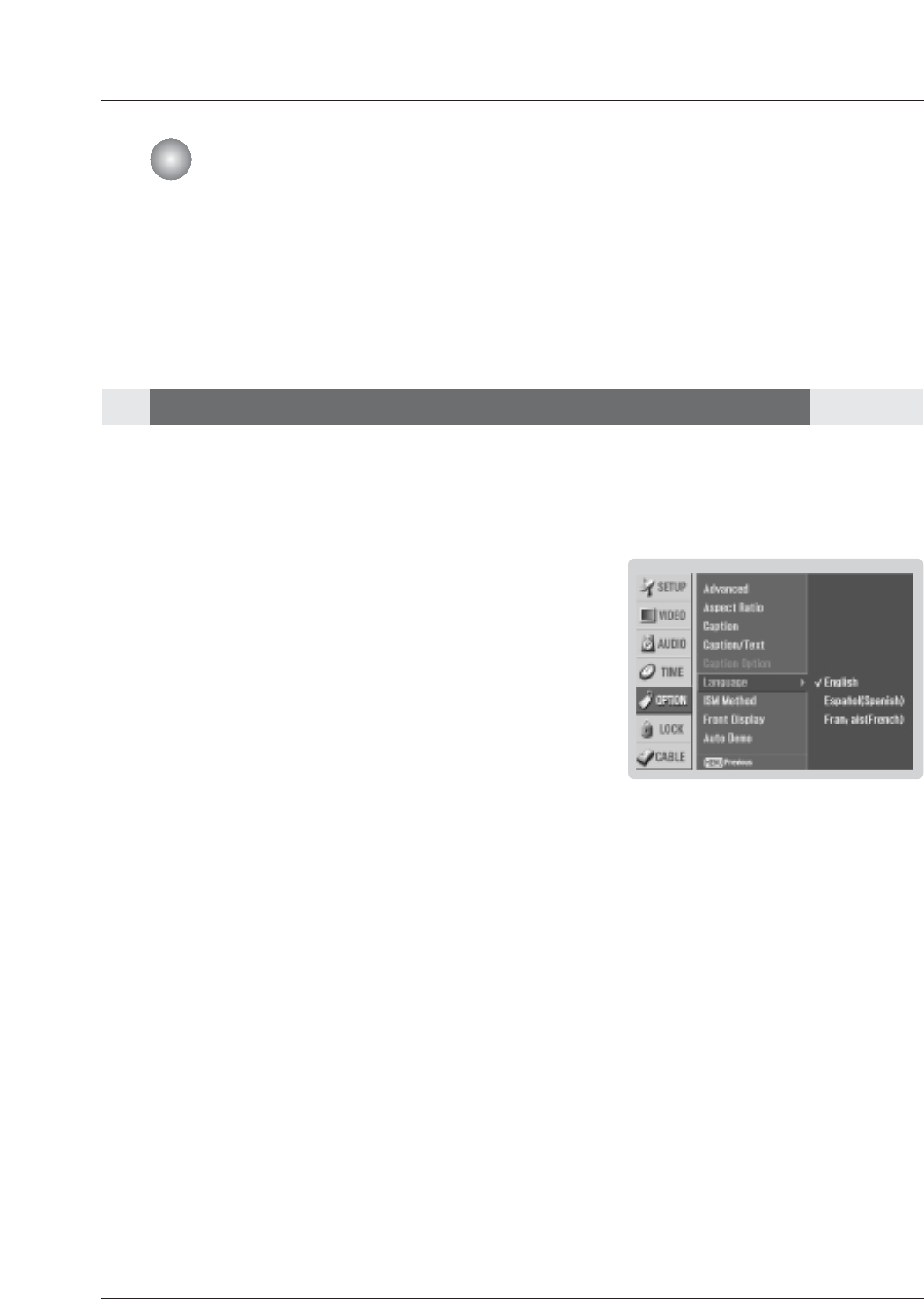
-The menus can be shown on the screen in the selected language. First select your language.
1. Press the MENU button and then use D/Ebutton to select the OPTION menu.
2. Press the Gbutton and then use D/Ebutton to select Language.
3. Press the Gbutton and then use D/Ebutton to select your desired language.
From this point on, the on-screen menus will be shown in the selected language.
4. Press EXIT button to return to TV viewing or press MENU button to return to the
previous menu.
Operation
TV Setup
TV Setup
On-screen Menus Language Selection
On-screen Menus Language Selection
Owner’s Manual 39
Operation
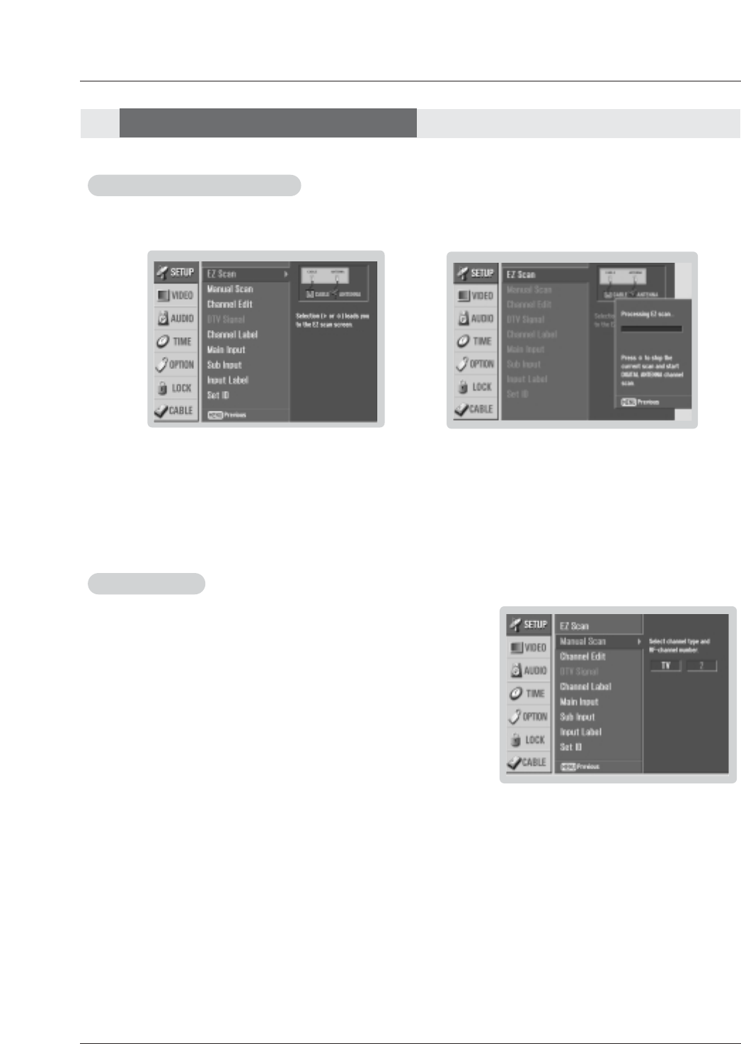
- Automatically finds all channels available through antenna or cable inputs, and stores them in memory on the channel list.
- Run EZ Scan again after any Antenna/Cable connection changes.
1. Press the MENU button and then use D/Ebutton to select the SETUP menu.
2. Press the Gbutton and then use D/Ebutton to select EZ Scan.
3. Press the ENTER button to begin the channel search.
Allow EZ Scan to complete the channel search cycle for ANTENNA, and CABLE.
EZ Scan (Channel Search)
EZ Scan (Channel Search)
1. Press the MENU button and then use D/Ebutton to select the SETUP menu.
2. Press the Gbutton and then use D/Ebutton to select Manual Scan.
3. Press the Gbutton and then use D/Ebutton to select TV, DTV, CATV, and
CADTV.
4. Press the Gbutton and then use D/Ebutton to select channel number you
want to add or delete.
5. Press the ENTER button to add or delete for the channel number.
6. Press EXIT button to return to TV viewing or press MENU button to return to the
previous menu.
Manual Scan
Manual Scan
Notes:
• This channel number is a physical channel number, which is different from the normal channel number shown in Channel
Edit.
• When a cable box connects to the physical channel 2,3 or 4 in the TV Guide On Screen system Setup, cable chan-
nels(CATV or CADTV) will not be scanned by EZ Scan or Manual Scan.
• When inserting the CableCARDTM, CATV, CADTV is not working in EZ Scan.
• TV: analog antenna(over-the-air) TV signal
DTV: digital antenna(over-the-air) TV signal
CATV: analog cable TV signal
CADTV: digital cable TV signal
Setup Menu Options
Setup Menu Options
40 Plasma TV
Setup Menu Options
Setup Menu Options
Note:
• When a cable box connects to the physical channel 2, 3, or 4 in TV Guide On Screen Setup, cable channels(CATV or
CADTV) will not be editable by Channel Edit. Instead, use the cable box's Channel Edit if available.
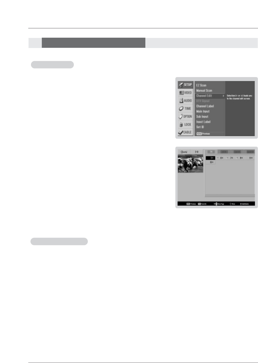
- Create two different types of channel lists in memory: “Custom list” and
“Favorite channel list” from the default channel list created from the EZ Scan
channel search.
- A custom list can be created by toggling each channel on or off with ENTER
button. The. The channels in the Custom List are displayed in black color, and
the channels deleted from the Custom List are displayed in gray color. Once a
channel is highlighted you can add or delete the channel by referring to the
small window at the top-left corner of the screen.You can create your own
Favorite List. Use the FAV button on the remote control when a channel is
highlighted and then you can add or delete the channel to/from the Favorite
List.
1. Press the MENU button and then use D/Ebutton to select the SETUP menu.
2. Press the Gbutton and then use D/Ebutton to select Channel Edit.
3. Press the Gbutton. You will now see a screen filled with channel numbers and
a preview picture.
4. Use D/E/F/Gbutton to select a channel and then use the ENTER button to
add or delete it. Press FAV button to add the channel to the Favorite List.
5. Press EXIT button to return to TV viewing or press MENU button to return to the
previous menu.
Channel Edit
Channel Edit
- Shows how strong your DTV signal is and whether you need to adjust your antenna or digital cable input.
The higher the signal strength, the less likely you are to experience picture degradation.
- DTV Signals: Only when the input signal is DTV or CADTV, this function is available.
1. Press the MENU button and then use D/Ebutton to select the SETUP menu.
2. Press the Gbutton and then use D/Ebutton to select DTV Signal.
3. View the on-screen signal strength monitor to see the quality of the signal being received.
5. Press EXIT button to return to TV viewing or press MENU button to return to the previous menu.
DTV Signal Strength
DTV Signal Strength
Operation
Owner’s Manual 41
Operation
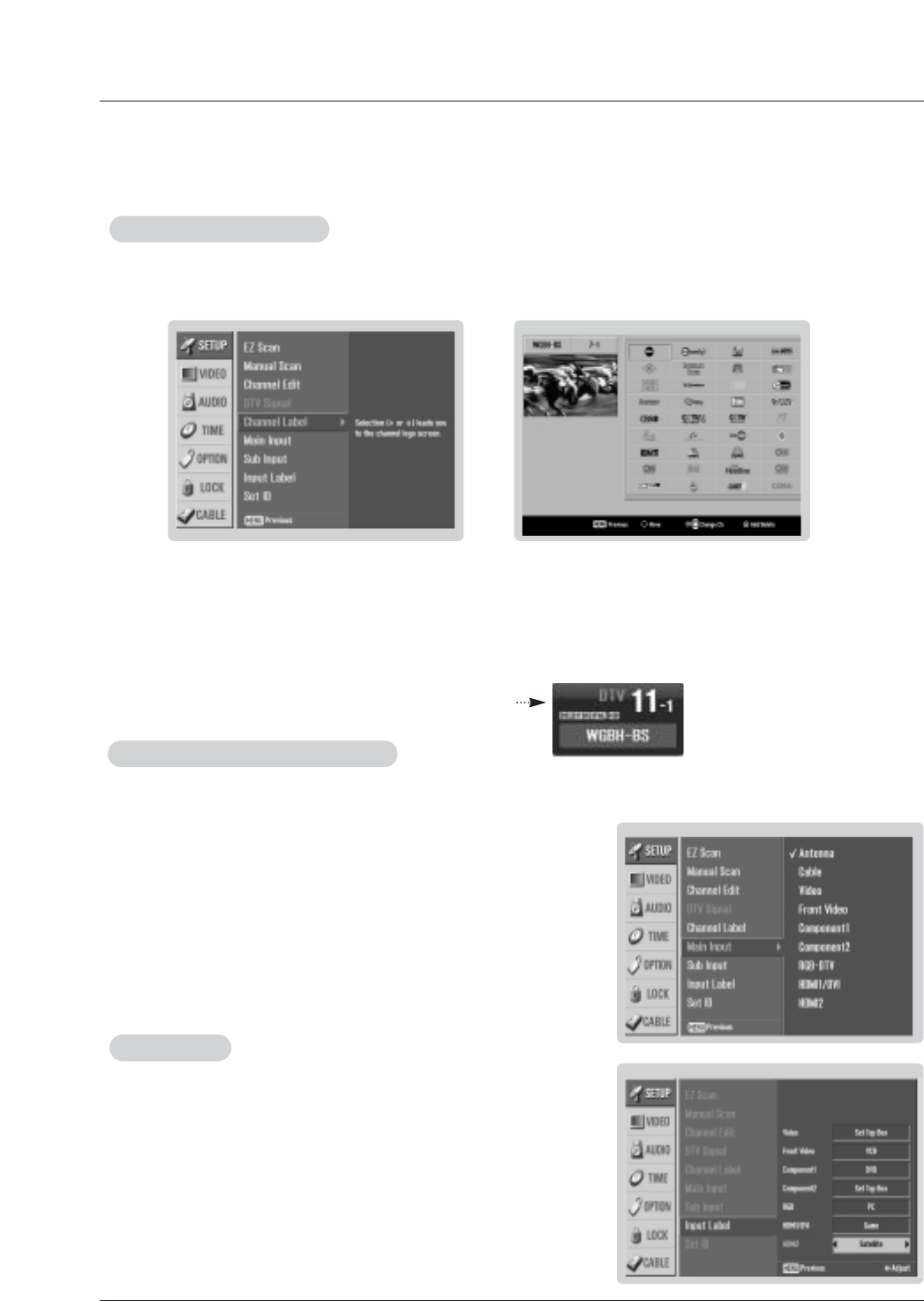
- Changes the picture source so you can watch your off-air TV, cable TV, VCR, DVD, or any
other devices that are connected to your TV.
1. Press the MENU button and then use D/Ebutton to select the SETUP menu.
2. Press the Gbutton and then use D/Ebutton to select Main Input.
3. Press the Gbutton and then use D/Ebutton to select the source: Antenna,
Cable, Video, Front Video, Component1, Component2, RGB-DTV (or RGB-
PC), HDMI1/DVI, HDMI2.
4. Press EXIT button to return to TV viewing or press MENU button to return to
the previous menu.
Main Picture Source Selection
Main Picture Source Selection
1. Press the MENU button and then use D/Ebutton to select the SETUP menu.
2. Press the Gbutton and then use D/Ebutton to select Input Label.
3. Press the Gbutton and then use D/Ebutton to select the source: Video, Front
Video, Component1, Component2, RGB, HDMI1/DVI or HDMI2.
4. Press EXIT button to return to TV viewing or press MENU button to return to
the previous menu.
Input Label
Input Label
- Choose preset labels for your channels.
- If a channel label is provided on the signal from the broadcasting station, the TV displays a short name for a channel -
even if you didn't preset a label for the channel.
1. Press the MENU button and then use D/Ebutton to select the SETUP menu.
2. Press the Gbutton and then use D/Ebutton to select Channel Label.
3. Press the Gbutton. You will now see a screen filled with Labels and a preview screen.
4. Use the CH +/- button to select a channel to Label.
5. Use D/E/F/Gbutton to select the appropriate label for the channel, then press ENTER button to set the Label to
the selected channel.
- If you press ENTER button, you will see the channel banner.
Channel Label Setup
Channel Label Setup
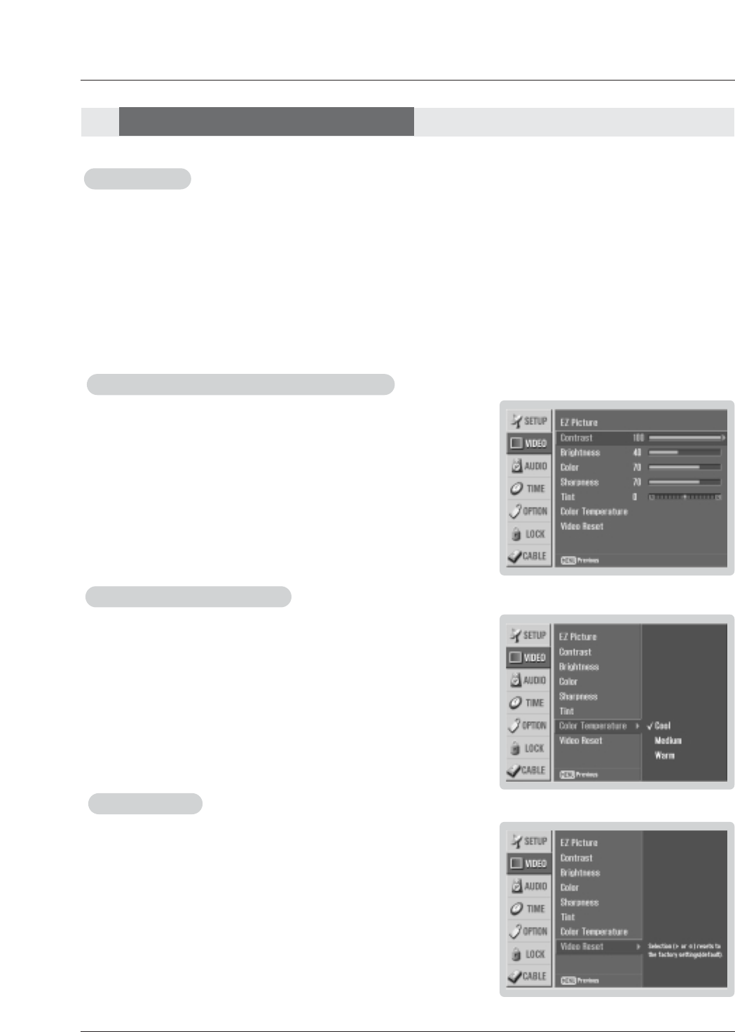
42 Plasma TV
- Use to quickly reset all the Video menu options to their original factory preset
values.
1. Press the MENU button and then use D/Ebutton to select the VIDEO menu.
2. Press the Gbutton and then use D/Ebutton to select Video Reset .
3. Press the Gbutton to reset the Video menu options to original values.
V
Video Reset
ideo Reset
Operation
- Adjust the picture appearance to suit your preference and viewing situations.
1. Press the MENU button and then use D/Ebutton to select the VIDEO menu.
2. Press the Gbutton and then use D/Ebutton to select the desired picture option
(Contrast,Brightness,Color,Sharpness, or Tint ).
3. Press the Gbutton and then use F/Gbutton to make appropriate adjustments.
4. Press EXIT button to return to TV viewing or press MENU button to return to the
previous menu.
1. Press the EZ PIC button repeatedly to select the picture appearance setup option as shown below:
Custom (your own settings), Daylight,Normal,Night Time,Movie,Video Game, and Sports.
• You can also use the VIDEO menu to adjust EZ Picture.
2. Press the EXIT button to save and return to TV viewing.
EZ Picture
EZ Picture
Manual Picture Control (
Manual Picture Control (Custom option)
option)
- Choose one of three automatic color adjustments. Set to warm to enhance hotter
colors such as red, or set to cool to see less intense colors with more blue.
1. Press the MENU button and then use D/Ebutton to select the VIDEO menu.
2. Press the Gbutton and then use D/Ebutton to select Color Temperature .
3. Press the Gbutton and then use D/Ebutton to select either Cool,Medium or
Warm.
4. Press EXIT button to return to TV viewing or press MENU button to return to the
previous menu.
Color
Color T
Temperature Control
emperature Control
- EZ Picture adjusts the TV for the best picture appearance. Select the preset value in the EZ Picture menu based on the
program category.
- When adjusting Video menu options (contrast, brightness, color, sharpness, tint, and color temperature) manually, EZ
Picture automatically changes to Custom.
-Daylight,Normal,Night Time,Movie,Video Game, and Sports settings are preset for optimum picture quality at
the factory and are not adjustable.
V
Video Menu Options
ideo Menu Options
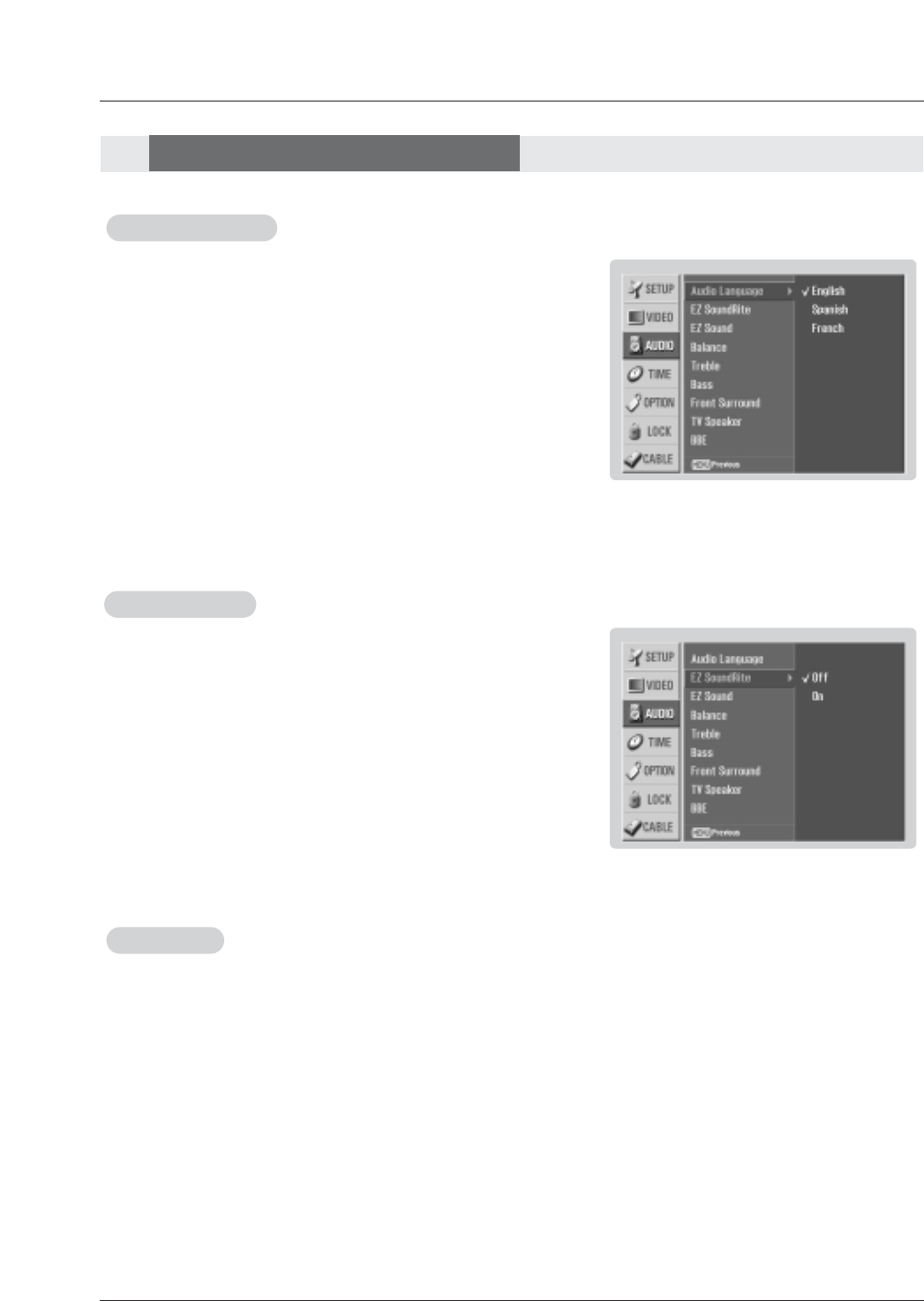
Owner’s Manual 43
Operation
- Other languages may be available if a digital signal is provided by the broad-
casting station.
1. Press the EZ SOUND button repeatedly to select the appropriate sound setup as shown below:
Custom (your own settings), Normal,Stadium,News,Music, and Theater.
• You can also adjust EZ Sound in the AUDIO menu.
2. Press EXIT button to save and return to TV viewing.
EZ Sound
EZ Sound
1. Press the MENU button and then use D/Ebutton to select the AUDIO menu.
2. Press the Gbutton and then use D/Ebutton to select Audio Language.
3. Press the Gbutton and then use D/Ebutton to select: English, Spanish, or
French.
4. Press EXIT button to return to TV viewing or press MENU button to return to
the previous menu.
Audio Language
Audio Language
- EZ Sound lets you enjoy the best sound without any special adjustment because the TV sets the appropriate sound
options based on the program content.
- When adjusting sound options (treble, bass, and front surround) manually, EZ Sound automatically switches Custom.
-Normal,Stadium,News,Music, and Theater are preset for good sound quality at the factory and are not
adjustable.
- Scans for changes in sound level during commercials, then adjusts the
sound to match the specified audio level. SoundRite makes sure that the vol-
ume level remains consistent whether you are watching a commercial or a
regular TV program.
1. Press the MENU button and then use D/Ebutton to select the AUDIO menu.
2. Press the Gbutton and then use D/Ebutton to select EZ SoundRite.
3. Press the Gbutton and then use D/Ebutton to select On or Off.
4. Press EXIT button to return to TV viewing or press MENU button to return to
the previous menu.
EZ SoundRite
EZ SoundRite
Audio Menu Options
Audio Menu Options
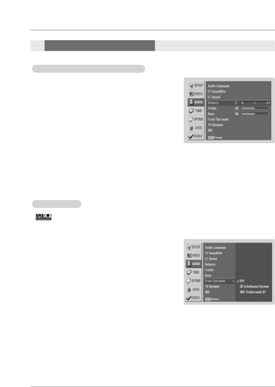
44 Plasma TV
Audio Menu Options
Audio Menu Options
Operation
1. Press the MENU button and then use D/Ebutton to select the AUDIO menu.
2. Press the Gbutton and then use D/Ebutton to select Front Surround.
3. Press the Gbutton and then use D/Ebutton to select Off,3D EchoSound
System or SRS (Sound Retrieval System) TruSurround XT..
•3D EchoSound System
Creates a stunning simulated stereo effects from any mono sound and a
realistic three-dimensional sound with a very wide and deep sound stage
into stereo sound.
•SRS TruSurround XT
Takes advantage of any multi-channel format without needing to add extra
speakers or equipment. Dialog clarity, bass enrichment, and the addition of
stereo audio enhancement that produces an immersive sound experience
from standard stereo material.
4. Press EXIT button to return to TV viewing or press MENU button to return to
the previous menu.
Front Surround
Front Surround
- is a trademark of SRS Labs, Inc.
- TruSurround XT technology is incorporated under license from SRS Labs, Inc.
- Manufactured under license from Dolby Laboratories. “Dolby” and the double-D symbol are trademarks of Dolby Laboratories.
1. Press the MENU button and then use D/Ebutton to select the AUDIO menu.
2. Press the Gbutton and then use D/Ebutton to select the desired sound option
(Balance,Treble, or Bass).
3. Press the Gbutton and then use F/Gbutton to make appropriate adjustments.
4. Press EXIT button to return to TV viewing or press MENU button to return to
the previous menu.
Manual Sound Control (
Manual Sound Control (Custom option)
option)
- Adjust the sound to suit your taste and room situations.
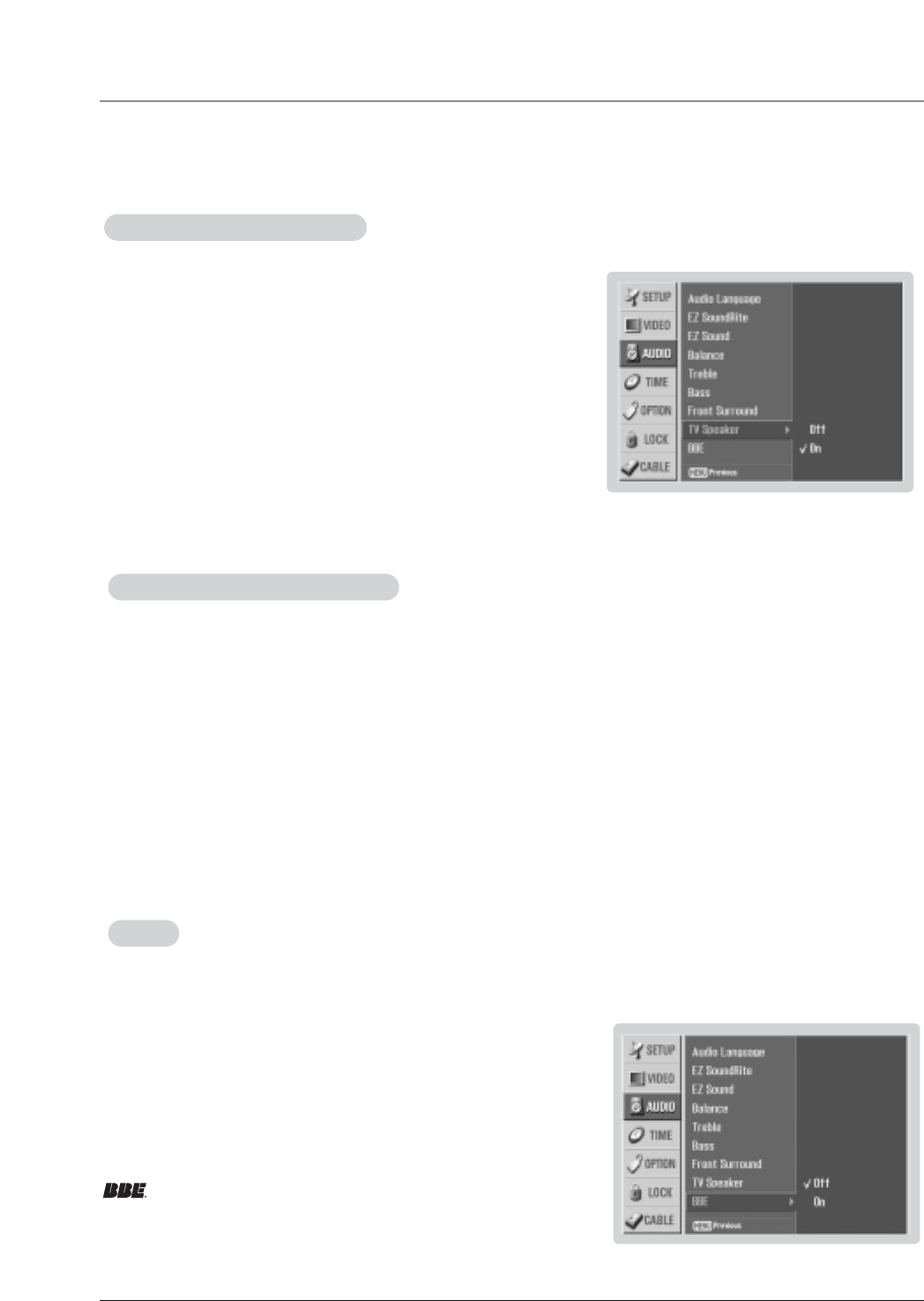
Owner’s Manual 45
Operation
1. Use the SAP button to select your desired MTS mode in analog signal. Each time you press the SAP button, Mono,
Stereo, or SAP appear in turn.
• If other languages available on the digital signal, select them with the SAP button.
2. Press EXIT button to save and return to TV viewing.
Stereo/SAP
Stereo/SAP Broadcasts Setup
Broadcasts Setup
- This TV can receive MTS stereo programs and any SAP (Secondary Audio Program) that accompanies the stereo program; if
the station transmits an additional sound signal as well as the original one.
- When having selected Stereo or SAP button on the remote control, this TV can only receive the signal in case that the TV sta-
tion transmits the proper signals.
- Mono sound is automatically received if the broadcast is only in Mono; even though Stereo or SAP has been selected.
- Select Mono if you want to listen to the mono sound in remote fringe areas during stereo/SAP broadcasting.
- Stereo or SAP can be received in Analog channel.
BBE
BBE
- BBE High Definition Sound restores clarity and presence for better speech intelligibility
and musical realism.
1. Press the MENU button and then use D/Ebutton to select the AUDIO
menu.
2. Press the Gbutton and then use D/Ebutton to select TV Speaker.
3. Press the Gbutton and then use D/Ebutton to select On or Off.
4. Press EXIT button to return to TV viewing or press MENU button to return to
the previous menu.
TV Speakers On/Of
TV Speakers On/Off Setup
f Setup
- Turn TV speakers off if using external audio equipment. Feature turns the
TV Speakers option On or Off.
1. Press the MENU button and then use D/Ebutton to select the AUDIO menu.
2. Press the Gbutton and then use D/Ebutton to select BBE.
3. Press the Gbutton and then use D/Ebutton to select On or Off.
4. Press EXIT button to return to TV viewing or press ENTER button to return to
the previous menu.
Manufactured under license from BBE Sound, Inc.
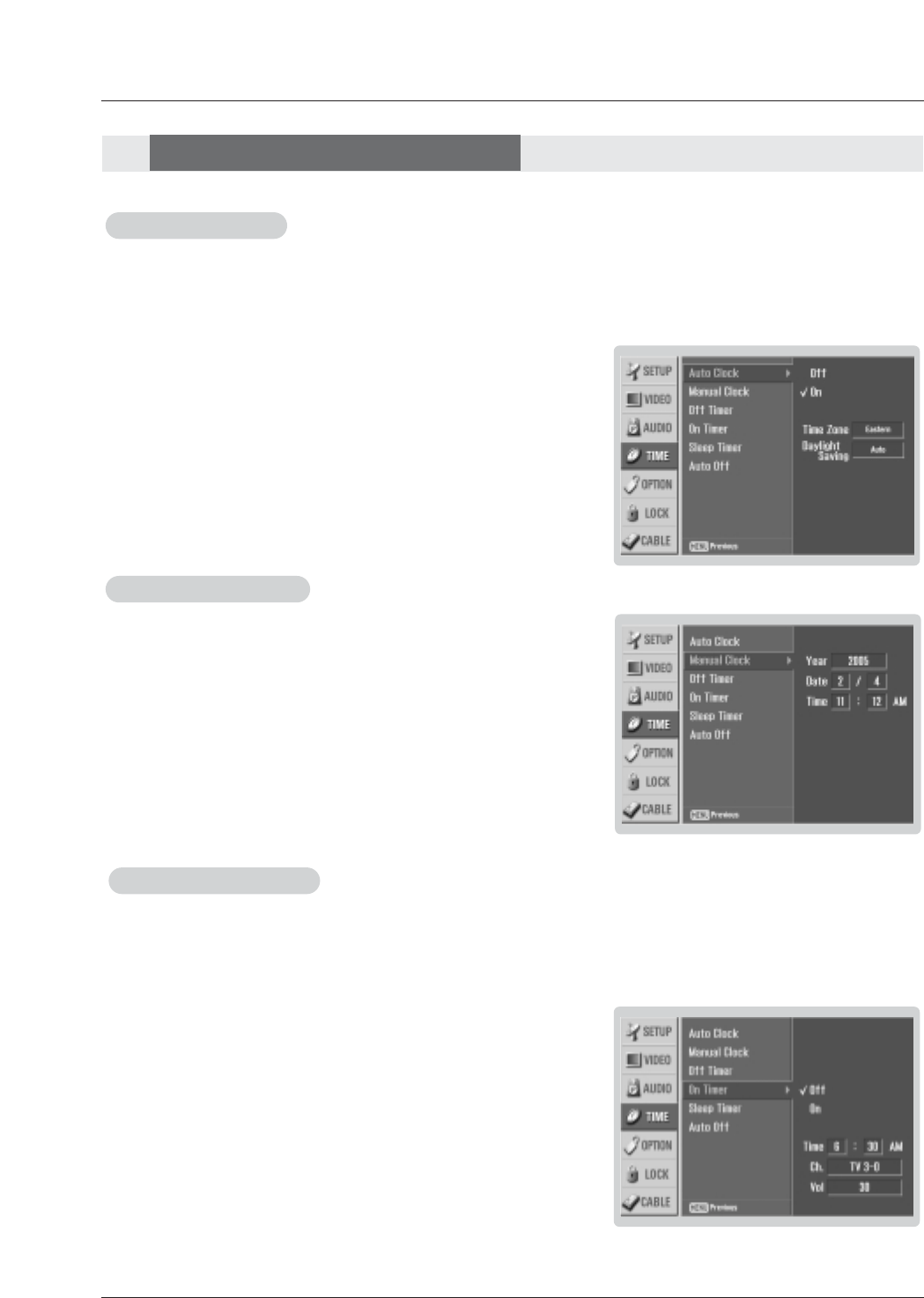
46 Plasma TV
Operation
- Timer function operates only if current time has been set.
- Off-Timer function overrides On-Timer function if they are set both set to the same time.
- The TV must be in standby mode for the On-Timer to work.
- If you do not press any button within 2 hours after the TV turns on with the On Timer function, the TV will automatically revert to
standby mode.
On/Of
On/Off
fT
Timer Setup
imer Setup
1. Press the MENU button and then use D/Ebutton to select the TIME menu.
2. Press the Gbutton and then use D/Ebutton to select Off Timer or On Timer.
3. Press the Gbutton and then use D/Ebutton to select On.
• To cancel On/Off timer function, select Off.
4. Press the Gbutton and then use D/Ebutton to set the hour.
5. Press the Gbutton and then use D/Ebutton to set the minutes.
6. For only On timer function
Press the Gbutton and then use D/Ebutton to select the channel at turn-on.
Press the Gbutton and then use D/Ebutton to set the sound level at turn-
on.
7. Press EXIT button to return to TV viewing or press MENU button to return to
the previous menu.
Auto Clock Setup
Auto Clock Setup
Manual Clock Setup
Manual Clock Setup
- If current time setting is wrong, reset the clock manually.
- When you set up TV guide on screen system, Manual Clock menu is not
worked.
1. Press the MENU button and then use D/Ebutton to select the TIME menu.
2. Press the Gbutton and then use D/Ebutton to select Manual Clock.
3. Press the Gbutton and then use F/Gbutton to select either the year, date,
or time option. Once selected, use the D/Ebutton to set the year, date, and
time options.
4. Press EXIT button to return to TV viewing or press MENU button to return to
the previous menu.
- The time is set automatically from a digital channel signal.
- The digital channel signal includes information for the current time provided by the broadcasting station.
- Set the clock manually, if the current time is set incorrectly by the auto clock function.
- When you set up TV guide on screen system, Auto Clock menu is not selected.
1. Press the MENU button and then use D/Ebutton to select the TIME
menu.
2. Press the Gbutton and then use D/Ebutton to select Auto Clock.
3. Press the Gbutton and then use D/Ebutton to select On.
4. Press the Gbutton and then use D/Ebutton to select your viewing area
time zone: Eastern,Central,Mountain,Pacific,Alaska, or Hawaii.
5. Press EXIT button to return to TV viewing or press MENU button to return to
the previous menu.
T
Time Menu Options
ime Menu Options
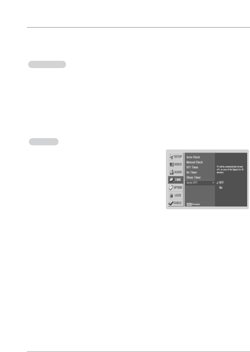
Owner’s Manual 47
Operation
Auto Of
Auto Off
f
- If set to on and there is no input signal, the TV turns off automatically after 10
minutes.
1. Press the MENU button and then use D/Ebutton to select the TIME menu.
2. Press the Gbutton and then use D/Ebutton to select Auto Off.
3. Press the Gbutton and then use D/Ebutton to select On or Off.
4. Press EXIT button to return to TV viewing or press MENU button to return to
the previous menu.
Sleep
Sleep T
Timer
imer
- The Sleep Timer turns the TV off at the preset time. Note that this setting is cleared when the TV is turned off.
- You can also set up the Sleep Timer in the TIME menu.
1. Press the TIMER button repeatedly to select the number of minutes. First the Off option appears on the screen,
followed by the following sleep timer options: 10, 20, 30, 60, 90, 120, 180, and 240 minutes.
2. When the number of minutes you want is displayed on the screen, press the ENTER button. The timer begins to
count down from the number of minutes selected.
3. To check the remaining minutes before the TV turns off, press the TIMER button once.
4. To cancel the Sleep Timer, press the TIMER button repeatedly to select Off.
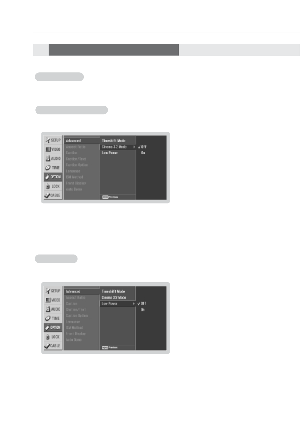
48 Plasma TV
Operation
Cinema 3:2 Mode Setup
- Set up the TV for the best picture appearance for viewing movies.
1. Press the MENU button and then use D/Ebutton to select the OPTION menu.
2. Press the Gbutton and then use D/Ebutton to select Advanced.
3. Press the Gbutton and then use D/Ebutton to select Cinema 3:2 Mode.
4. Press the Gbutton and then use D/Ebutton to select On or Off.
5. Press EXIT button to return to TV viewing or press MENU button to return to the previous menu.
Low Power
Low Power
- Low power reduces the plasma display power consumption.
1. Press the MENU button and then use D/Ebutton to select the OPTION menu.
2. Press the Gbutton and then use D/Ebutton to select Advanced.
3. Press the Gbutton and then use D/Ebutton to select Low power.
4. Press the Gbutton and then use D/Ebutton to select On or Off.
• When you select On, the screen darkens.
5. Press EXIT button to return to TV viewing or press MENU button to return to the previous menu.
Option Menu Features
Option Menu Features
TimeShift Mode
- See Page 71~72 for TimeShift functions.
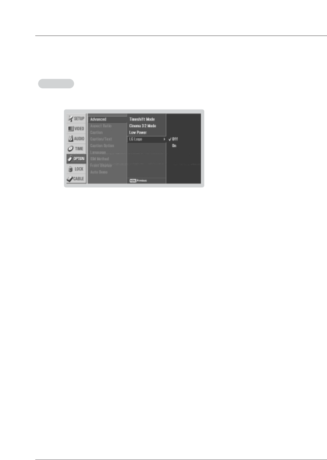
Owner’s Manual 49
Operation
LG Logo
LG Logo
- This function is only applied to 60PY2DR model.
1. Press the MENU button and then use D/Ebutton to select the OPTION menu.
2. Press the Gbutton and then use D/Ebutton to select LG Logo.
3. Press the Gbutton and then use D/Ebutton to select On or Off.
• When you select On, the Logo is lighting.
4. Press EXIT button to return to TV viewing or press MENU button to return to the previous menu.

50 Plasma TV
Option Menu Features
Option Menu Features
Operation
Aspect Ratio Control
Aspect Ratio Control
- Lets you choose the way an analog picture with a 4:3 aspect ratio is displayed on your TV with a 16:9 ratio picture format.
When you receive an analog picture with a 4:3 aspect ratio on your 16:9 TV, you need to specify how the picture is to be dis-
played.
- If you are viewing a picture with a 16:9 aspect ratio, you can’t use the Horizon aspect ratio option.
- Horizon aspect ratio is not available for Component 1-2 (720p/1080i)/RGB-DTV (720p/1080i)/HDMI1/DVI-DTV
(720p/1080i)/DTV(720p/1080i) input source.
- RGB-PC/DVI-PC input source use 4:3 or 16:9 aspect ratio.
-Note: If a fixed image is displayed on the screen for a long time, that fixed image may become imprinted on the screen and
remain visible.
•Set By Program
Selects the proper picture proportion to match the source’s image. (4:3 →4:3, 16:9 → 16:9)
•4:3
Choose 4:3 when you want to view a picture with an original 4:3 aspect ratio, with black bars appearing at both
the left and right sides.
•16:9
Choose 16:9 when you want to adjust the picture horizontally, in a linear proportion to fill the entire screen.
•Horizon
Choose Horizon when you want to adjust the picture in a non-linear proportion, that is, more enlarged at both
sides, to create a spectacular view.
•Zoom 1
Choose Zoom 1 when you want to view the picture without any alteration. However, the top and bottom portions
of the picture will be cropped.
•Zoom 2
Choose Zoom 2 when you want the picture to be altered, both vertically extended and cropped. The picture tak-
ing a halfway trade off between alteration and screen coverage.
•Cinema Zoom
Choose Cinema Zoom when you want to enlarge the picture in correct proportion. Note: When enlarging or
reducing the picture, the image may become distorted.
You can adjust the enlarge proportion of Cinema Zoom using D/Ebutton. The adjustment range is 1~16.
1. Press the RATIO button repeatedly to select the desired picture format.
You can also adjust Aspect Ratio in the OPTION menu.
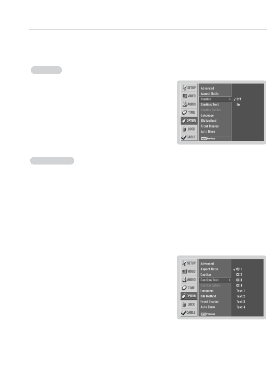
Owner’s Manual 51
Operation
Caption/T
Caption/Text
ext
Analog Broadcasting System Captions
- Select a caption mode for displaying captioning information if provided on a program.
- Analog caption displays information at any position on the screen usually the program's dialog.
- Text displays information, usually at the bottom position and is used for a data service, generally not program related.
- Caption/Text, if provided by the broadcaster, would be available for both digital and analog channels on the Antenna/Cable.
- This TV is programmed to remember the caption/text mode it was last set to, when you turn the power off.
1. Press the MENU button and then use D/Ebutton to select the OPTION
menu.
2. Press the Gbutton and then use D/Ebutton to select Caption/Text.
3. Press the Gbutton and then use D/Ebutton to select caption: CC1,CC2,CC3,
CC4,Text1,Text2,Text3, or Text4.
•CAPTION
The term for the words that scroll across the bottom of the TV screen; usu-
ally the audio portion of the program provided for the hearing impaired.
•TEXT
The term for the words that appear in a large black frame and almost cover
the entire screen; usually messages provided by the broadcaster.
4. Press EXIT button to return to TV viewing or press MENU button to return to
the previous menu.
1. Use the CC button repeatedly to select Caption CC1,CC2,CC3,CC4,Text1,Text2,Text3, or Text4.
•EZ Mute shows the selected captions option (if available on program) when the TV sound is muted
.2. Press EXIT button to save and return to TV viewing.
• You can also use the OPTION menu to select Caption/Text.
Caption
Caption
1. Press the MENU button and then use D/Ebutton to select the OPTION
menu.
2. Press the Gbutton and then use D/Ebutton to select Caption.
3. Press the Gbutton and then use D/Ebutton to select On or Off.
4. Press EXIT button to return to TV viewing or press MENU button to return to
the previous menu.
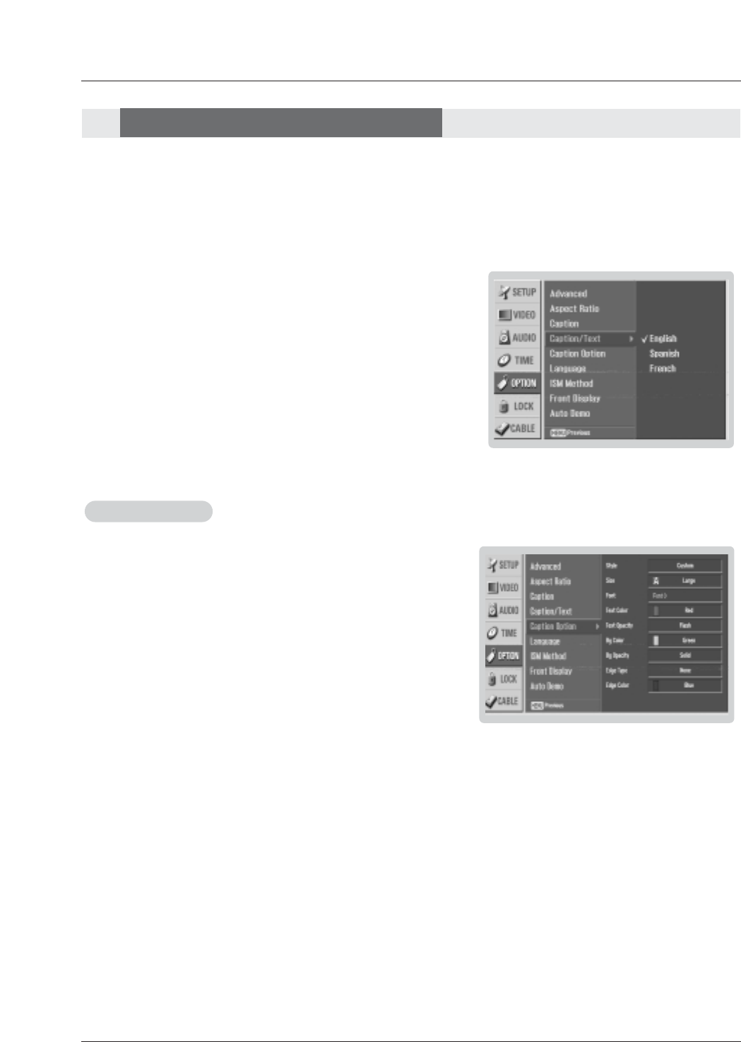
52 Plasma TV
Option Menu Features
Option Menu Features
Operation
Caption Option
Caption Option
- Customize the DTV/CADTV captions that appear on your screen.
1. Press the MENU button and then use D/Ebutton to select the OPTION
menu.
2. Press the Gbutton and then use D/Ebutton to select Caption Option.
3. Press the Gbutton and then use F/Gbutton to select Custom.
4. Use D/Ebutton to customize the Style, Font, etc., to your preference. A pre-
view icon is provided at the bottom of the screen, use it to see the caption lan-
guage.
•Size: Set the size the words will appear in.
•Font: Select a typeface for the words.
•Text Color: Choose a color for the text.
•Text Opacity: Specify the opacity for the text color.
•Bg (Background) Color: Select a background color.
•Bg (Background) Opacity: Select the opacity for the background color.
•Edge Type: Select an edge type.
•Edge Color: Select a color for the edges.
5. Press EXIT button to return to TV viewing or press MENU button to return
to the previous menu.
Digital Broadcasting System Captions
- Choose the language you want the DTV/CADTV Captions to appear in.
- Languages can be chosen for digital sources only if they are included on the program.
1. Press the MENU button and then use D/Ebutton to select the OPTION
menu.
2. Press the Gbutton and then use D/Ebutton to select Caption/Text.
3. Press the Gbutton and then use D/Ebutton to select available caption lan-
guages: English,Spanish, or French.
4. Press EXIT button to return to TV viewing or press MENU button to return to
the previous menu.
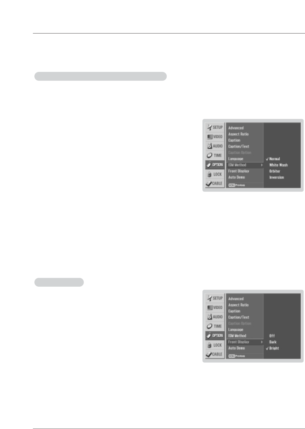
Owner’s Manual 53
Operation
- A frozen still picture from a PC/video game displayed on the screen for prolonged periods will result in an ghost
image remaining; even when you change the image. Avoid allowing any fixed image to remain on the TV's screen
for a long period of time.
1. Press the MENU button and then use D/Ebutton to select the OPTION
menu.
2. Press the Gbutton and then use D/Ebutton to select ISM Method.
3. Press the Gbutton and then use D/Ebutton to select either Normal,White
wash,Orbiter or Inversion .
•Normal
If image sticking is never a problem, ISM is not necessary - set to Normal.
•White wash
White Wash removes permanent images from the screen.
Note: An excessive permanent image may be impossible to clear entirely with
White Wash. To return to normal viewing, press the any button.
•Orbiter
Orbiter may help prevent ghost images. However, it is best not to allow any
fixed image to remain on the screen. To avoid a permanent image on the
screen, the image will move once per minute: Right →Right → Downside →
Downside →Left →Left →Upside →Upside.
•Inversion
Inversion will automatically invert the plasma display panel color every 30
minutes.
4. Press EXIT button to return to TV viewing or press MENU button to return to
the previous menu.
ISM (Image Sticking Minimization) Method
ISM (Image Sticking Minimization) Method
Front Display
Front Display
1. Press the MENU button and then use D/Ebutton to select the OPTION
menu.
2. Press the Gbutton and then use D/Ebutton to select Front Display.
3. Press the Gbutton and then use D/Ebutton to select Off,Dark and Bright.
4. Press EXIT button to return to TV viewing or press MENU button to return to
the previous menu.
- Illuminates brightly when the set is turned on. The LED displays current TV
status.
- This function is only applied to 50/60PY2DR model.
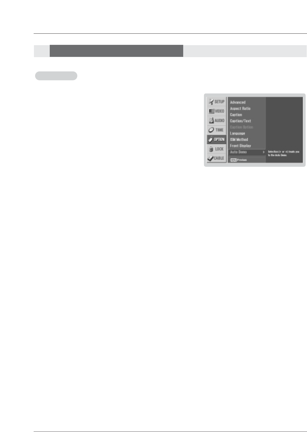
54 Plasma TV
Operation
Auto Demo
Auto Demo
- Displays the slide show to explain the main features of this TV.
1. Press the MENU button and then use D/Ebutton to select the OPTION
menu.
2. Press the Gbutton and then use D/Ebutton to select Auto Demo.
3. Press EXIT button to stop Auto Demo.
Option Menu Features
Option Menu Features

Owner’s Manual 55
Operation
Parental Control can be used to block specific channels, ratings and other viewing sources.
The Parental Control Function (V-Chip) is used to block program viewing based on the ratings sent by the broadcasting station.
The default setting is to allow all programs to be viewed. Viewing can be blocked by the type of program and by the categories
chosen to be blocked. It is also possible to block all program viewing for a time period. To use this function, the following must be
done :
1. Set ratings and categories to be blocked.
2. Specify a password
3. Enablethe lock
V-Chip rating and categories
Rating guidelines are provided by broadcasting stations. Most television programs and television movies can be blocked by TV
Rating and/or Individual Categories. Movies that have been shown at the theaters or direct-to-video movies use the Movie Rating
System (MPAA) only.
Ratings for Movies previously shown in theaters:
Movie Ratings :
• Blocking Off (Permits all programs)
• G (General audience)
• PG (Parental guidance suggested)
• PG-13 (Parents strongly cautioned)
• R (Restricted)
• NC-17 (No one 17 and under admitted)
• X (Adult only)
If you set PG-13 : G and PG movies will be available , PG-13, R, NC-17 and X will be blocked.
Ratings for Television programs including made-for-TV movies :
• TV-G (General audience)
• TV-PG (Parental guidance suggested)
• TV-14 (Parents strongly cautioned)
• TV-MA (Mature audience only)
• TV-Y (All children)
• TV-Y7 (Children 7 years older)
TV Rating Children:
• Age (applies to TV-Y, TV-Y7)
• Fantasy Violence (applies to TV-Y7)
TV Rating General:
• Age (applies to TV-G, TV-PG, TV-14, TV-MA)
• Dialogue - sexual dialogue (applies to TV-PG, TV-14)
• Language - adult language (applies to TV-PG, TV-14, TV-MA)
• Sex - sexual situations (applies to TV-PG, TV-14, TV-MA)
• Violence (applies to TV-PG, TV-14, TV-MA)
Input Block
• Video, Front Video (On, Off)
• Component 1, 2 (On, Off)
• RGB, HDMI1/DVI,HDMI2 (On, Off)
Lock Menu Options
Lock Menu Options
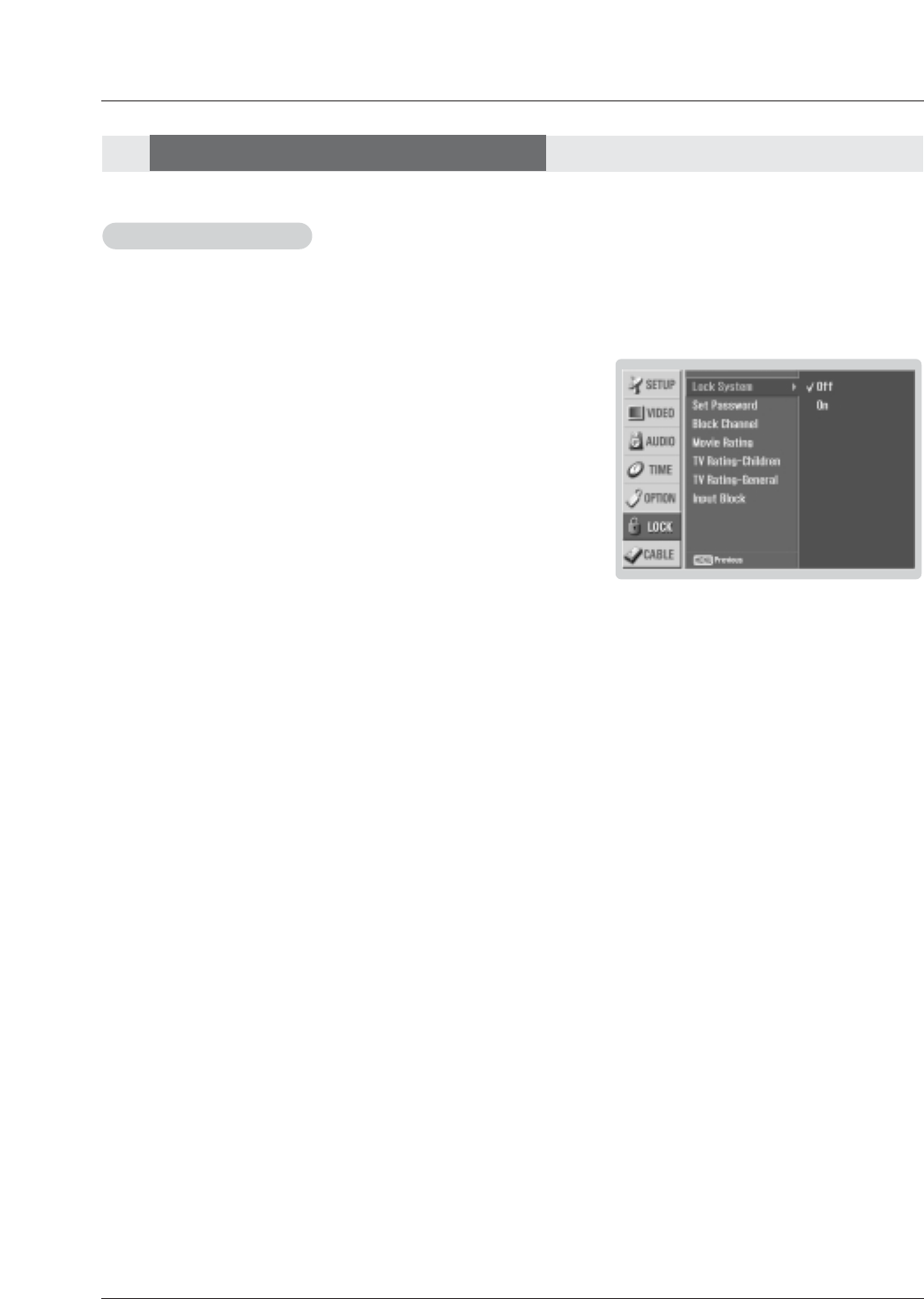
56 Plasma TV
Operation
Parental Lock Setup
Parental Lock Setup
1. Press the MENU button and then use D/Ebutton to select the LOCK menu.
Then, press the Gbutton
• If Lock is already set, enter the password as requested.
• The TV is set up with the initial password “0-0-0-0”.
2. Use the D/Ebutton to choose from the following Lock Menu options. Once the
option is selected, change the settings to your preference.
•Lock System: Activates or disables the blocking scheme you set up previ-
ously.
•Set Password: Change the password by inputting a new password twice.
•Block Channel: Blocks any channels that you do not want to watch or
that you do not want your children to watch.
•Movie Rating (MPAA): Blocks movies according to the movie ratings lim-
its specified, so children cannot view certain movies. You can set the rat-
ings limit by blocking out all the movies with the ratings above a specified
level. Keep in mind that the movie ratings limit only applies to movies
shown on TV, not TV programs, such as soap operas.
•TV Rating-Children: Prevents children from watching certain children's TV
programs, according to the ratings limit set. The children rating does not
apply to other TV programs. Unless you block certain TV programs intend-
ed for mature audiences in the TV Rating - sub menu, your children can
view those programs.
•TV Rating-General: Based on the ratings, blocks certain TV programs that
you and your family do not want to view.
•Input Block: Enables you to select a source to block from the external
source devices you have hooked up.
3. Press EXIT button to return to TV viewing or press MENU button to return to
the previous menu.
Note:
• If you ever forget your password, key in ‘7’, ‘7’, ‘7’, ‘7’ on the remote control.
- Set up blocking schemes to block specific channels, ratings, and external viewing sources.
- A password is required to gain access to this menu if the Lock System is turned on.
Lock Menu Options
Lock Menu Options
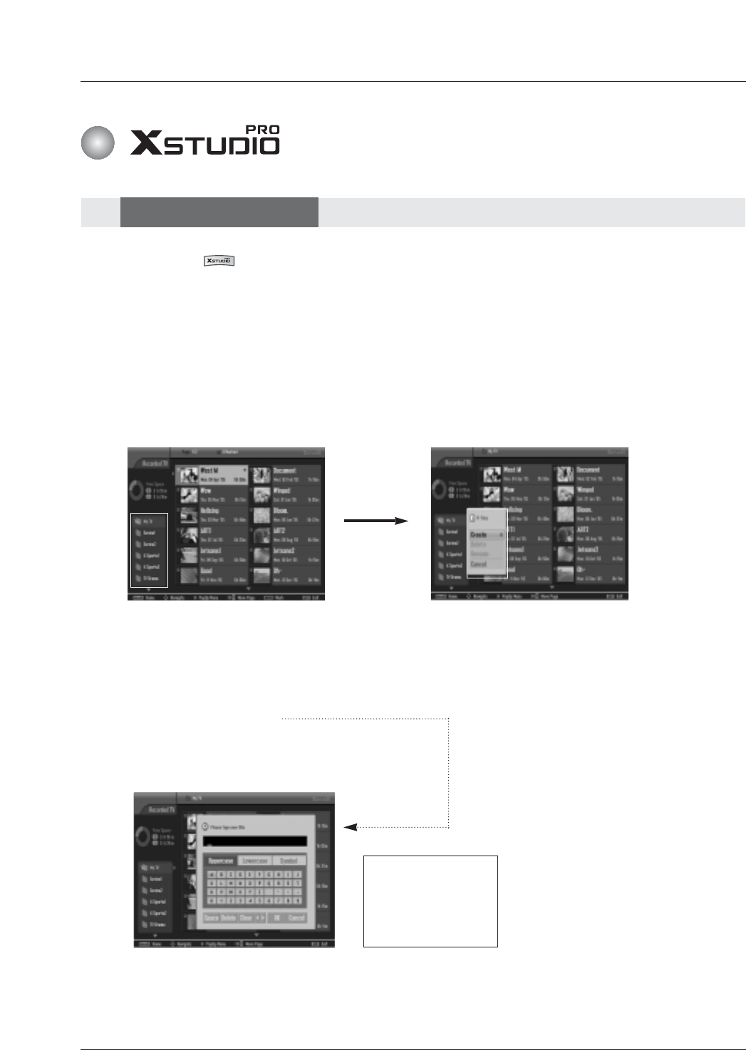
Owner’s Manual 57
Operation
1. Select the Recorded TV in HOME menu or press the REC LIST button to view the recording list as shown below.
A. B.
- When you press the button, HOME menu is displayed. From here, you can view the recorded program list.
- Or pressing the REC LIST button, you directly enter the recording list.
3. Select the desired folder in the folder list and then press the ENTER button to view the detailed menu.
•Create:Create new folder.
•Delete:Delete folder (except ‘My TV’).
•Rename:Edit folder name.
•Cancel:Close the detailed menu.
-> Use the D/E/F/G
button to input the
wanted name.
-> And then move the
OK and press the
ENTER button to save.
C.
C.
Recorded TV
Recorded TV
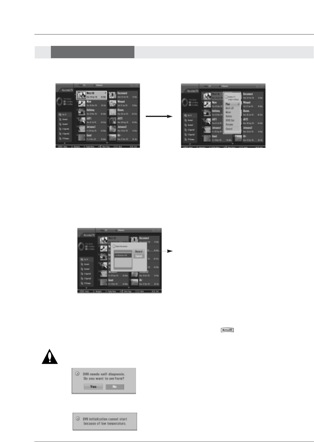
58 Plasma TV
Operation
Recorded TV
Recorded TV
- The current thumbnail recorded list is shown above.
1. Use the CH +/- button to navigate thumbnail photo in pages.
2. Use MARK button to add or delete the marked photo to the mark list and only marked photos are toggling.
3. Use D/E/F/Gbutton to navigate the appropriate thumbnail photo, then press the ENTER button to open the pop-up
menu.
•Play:Begin playback of selected recording.
•Mark All:mark all photos on the screen.
•Unmark All:Change marked photos to unmarked photos.
•Move:Move program saved in HDD to the other folder.
•Delete:Delete the selected recording. This menu is only available in HDD mode.
•DVHS Out:When DVHS is connected, selected program is saved to the DVHS.
•Rename:Edit recorded name.
•Cancel:Close the Pop-up menu.
4. Repeatedly, press REC LIST button or EXIT button to return to TV viewing or press button to return to the
previous menu.
D.
D.
• Through the 1394, can be record-
ed the desired program.
When a device is not connected
to the 1394 port, “No DVHS
Connected” is dis-played on the
screen.
- If the HDD has a problem on performing a function (Recording, Photo, Music) related with
DVR, question both Yes or No which being displayed this message to initialize HDD as
shown below.
- If temperature is below zero(0°), this message is displayed to initialize HDD as shown
below.
- If you selects Yes, it can be deleted the Recorded
List, Photo/Music list etc. because of initializing
HDD. Even If you selects No, it can't be worked
DVR operation of playback, record etc.
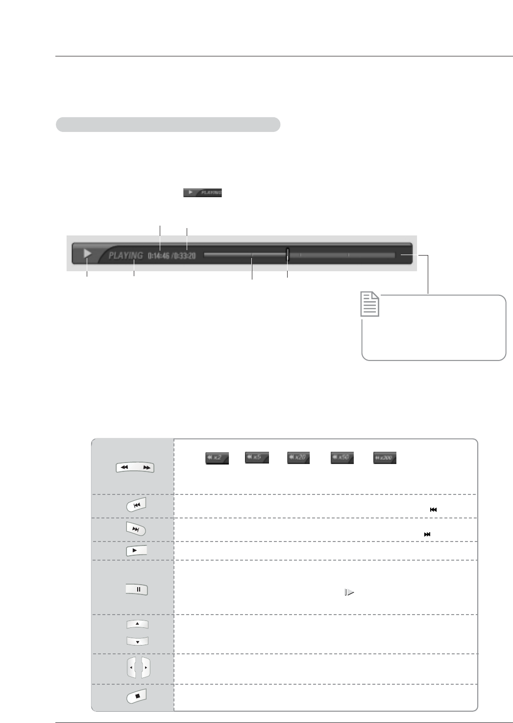
(In the condition of not setting a section to repeat)
- If you wish to return to a initial portion of playback program, press the button.
Owner’s Manual 59
Operation
On playing the recorded program, play
On playing the recorded program, play
- You can play the selected program in the recorded program list.
1.Play a recorded program.
2.On playing, You can see a diversified playback screen as shown below.
• At first, it is showed as marking .Then press the ENTER button to display the progress bar.
• To disappear a recorded program icon, press the EXIT button.
2
3
* The ‘Progress Bar’?
This function indicates a possible
DVR reshowing section ,a cur-
rent on-screen and real on-
broadcasting position, a section
of section-recording.
1. Indicates movement of recorded program.
2. Indicates status of recorded program.
3. Indicates elasped playback time.
4. Indicates total playback time.
5. Indicates 15 minute intervals from recorded program start time.
(Total - one hour).
6. Indicates current playback position.
5
4
6
1
W
WUsing the remote control
- When playing, press the REW (FF )or FF (GG)button.
• Like -> -> -> -> in a row.
2 times 5 times 20 times 50 times 300 times
• If the button is pressed continuously, it changes like above. If the button is taken
away, it changes a normal playback.
(In the condition of not setting a section to repeat)
- If you wish to return to a last portion of playback program, press the button.
- Press the PLAY (G)button to return to a normal playback.
- You can shift playback to any point within playing the recorded program
- During playback, press the Pause ( II ) button.
• Still screen is displayed.
• Repetedly press the Pause ( II ) button to advance frame by frame.
• When pressing the Pause ( II ) button, longly, will be showed.
• Unless a remote control input after a pause, return to the condition of playback in 15
minutes.
• If you press the D/Ebutton on piaying, the screen will be jumped back and forth
in the current screen.
• Pressing the Dbutton, the screen will be jumped 20 seconds in the front.
• Pressing the Ebutton, the screen will be jumped 8 seconds in the back.
• After moving to the back using the Gbutton on playing, press the the Fbutton to
be directly returned to the prior screen.
- If you press the STOP ( JJ)button, you can watch the TV.
• After marking the “ J ”, this program is ended in 15 minutes.
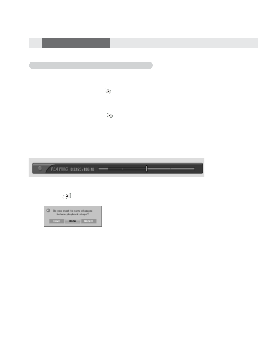
60 Plasma TV
Operation
Recorded TV
Recorded TV
On playing the recorded program, edit a section
On playing the recorded program, edit a section
- You can save the desired screen in the recorded program list after editing the recorded program..
1. At the point of desired start , press the button.
• The progress bar which be editied will be showed the red color.
• It can be possible as search (FF or GG), pause while editing the section.
2. At the point of desired finish , press the button.
• Stop editing the section.
3. Repeatedly play the above 1,2 phase, it can be possible to edit some programs.
4. If you press the button to stop the recorded program playback, this message is displayed as shown below.
•Save: Save contents of editing the section and finish the playback
of recorded program.
•Undo: Don’t save contents of editing the section and finish the
playback of recorded program.
•Cancel: The screen is disappeared and the playback is continued.
Notes:
• It can be possible to play on the recording / reserved recording
• It can be possible to occur a noise by a hard-disk on playing the recorded program. The noise is irrelevant the profi-
ciency and creditability of product, the noise occurred more than adequate is the same as good product.
• In case saving the content of editing the section, delete the portion not to select.
• When power off on editing, It can be possible not to save the content of editing. You do press the STOP (
JJ
)button
after checking the recording list.
• Editing the section can be possible to the maxium of 10.
• You can not save editing of less than 10 seconds.
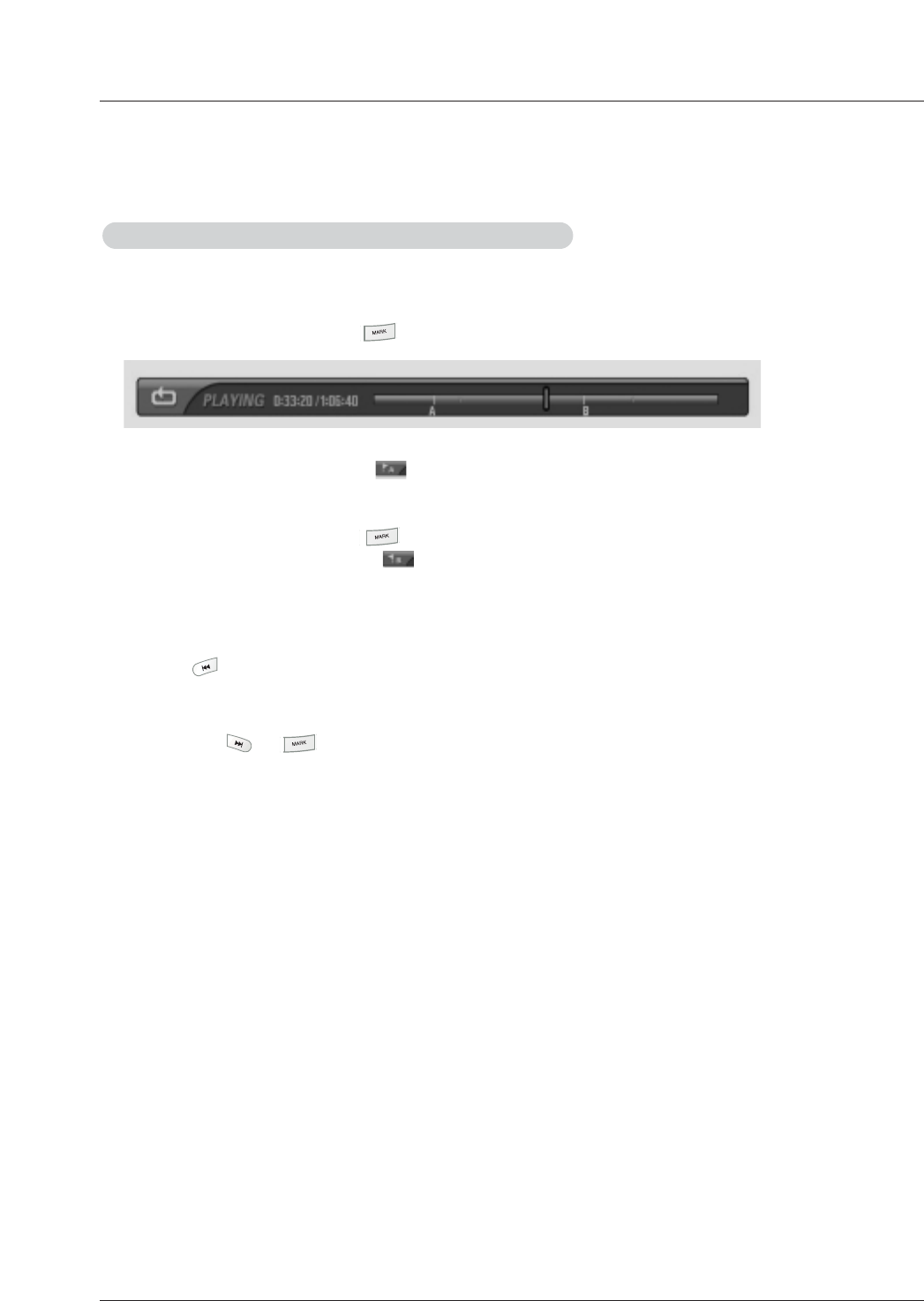
Owner’s Manual 61
v
On playing the recorded program, repeat a section
On playing the recorded program, repeat a section
- You can set the section and repeatedly view on playig the recorded program.
1. At the point of desired start, press the button.
• At start points, it is showed as marking .
2. At the point of desired finish, press the button.
• At finiah points, it is showed as marking .
• Repeatedly play the marked section.
• You can not make sections of less than 5 seconds.
• The progress bar which be repeated will be showed the blue color.
3. Press the button to move the position of the start point.
• Return to the start point of marked section and then start the playback.
4. If you press the or button to stop playing the repeat section.
Notes:
•It can be possible a function as search (Rew / FF), Pause, edit a section while repeating a section.
• When setting the section of start and finish, it can be possible both of Rew and FF.

62 Plasma TV
Operation
What is Memory Card
What is Memory Card
Precaution for Using the Memory Card
Precaution for Using the Memory Card
Notes on Memory Card
Notes on Memory Card
This is a device equipment to communicate the data between AV external equipment. It’s used to a digital cam-
era, camcorder, MP3 player, notebook or PDA.
- Insert the memory card correctly.
- Don’t insert the metal substances into the slots of the memory card.
- Do not bend, drop or apply strong shock to memory card.
- After pulling the memory card out from the TV, please keep the memory stick in a appropriate case to prevent
static shock.
- The stored data may be changed or lost as a result of misuse, static electricity.
- Do not turn the power off while using the memory card (loading or erasing).
- Don’t eject the memory card while using the it. Otherwise, it may cause a data loss or card damage.
- Only Insert one card to each slot.
- To prevent a change or loss for stored data, don’t misuse the TV or don’t let static electricity or electrical noise
for TV.
- This Company takes no responsibility for problems such as the damage or malfunction that occurs while using
the TV set, inappropriate TV settings, or any other reasons, except for defects or malfunctions intrinsic to the
product.
- Ensure to use a memory card that lists the manufacturers name and serial number.
- The manufacturer shall not be responsible for damaged data. Be careful to avoid data damage, and back up
your files.
- Make sure to comply with the following steps when ejecting a memory card.
- Each Memory Card is complied with standard.
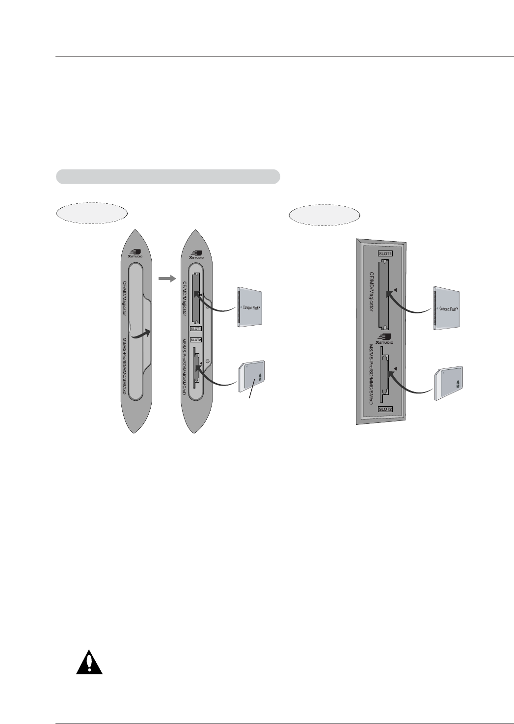
Owner’s Manual 63
Operation
W
WInserting a Card
1. Insert the Memory Card to Memory card slots of TV side panel.
2. Two slots support defferent types of the Memory Cards.
3. If Memory Card is not inserted, each slot is disable.
W
WEjecting a card
1. Press the M/C EJECT button on the remote control.
2. Select the Slot 1 or Slot 2 based on the inserted card location.
If selecting Cancel, OSD is disappeared.
3. Eject the card with the hand.
Note: If you insert or eject a card in one slot while the card in another slot (slot 1 or slot 2) is in use, the product can
run abnormally.
A.
A.
1.Using the Memory Card
Entry Modes- 1.Using the Memory Card / 2. Enter the HOME Menu
Caution: Before you remove the memory card from the slot, do
not forget to press the M/C EJECT button on the
remote control and make it safe to eject the memory
card, or the memory card may be damaged.
How to insert and eject the Memory Card
How to insert and eject the Memory Card
label-side
upward
50/60PY2DR 50PX4DR
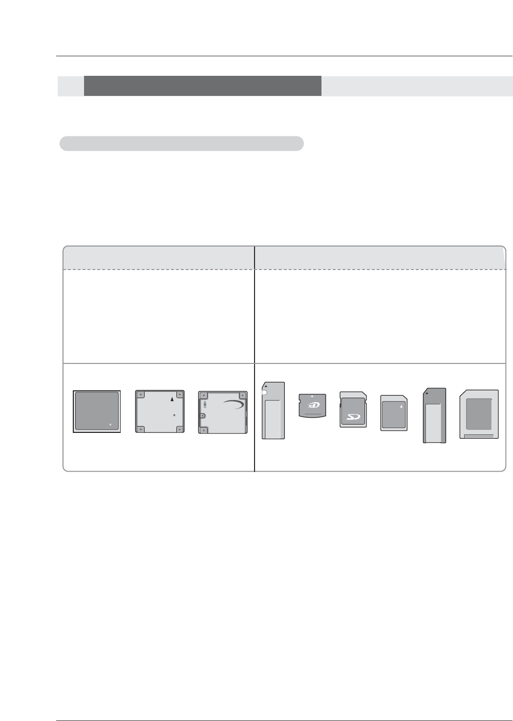
64 Plasma TV
Operation
Memory Card type and Memory Card capacity
Memory Card type and Memory Card capacity
- 9 types of Memory Card can be used for this Plasma TV.
- Playback speed can vary dependent on the card type.
-Unsupported or damaged photo or music files can cause errors. Do not try to change the file extension of unsupported file --
-types to the file extension of supported file types.
Slot 1 Slot 2
•CF (CompactFlash) : 4GB
•MD (Microdrive) : 4GB
•CF+|| (MagicStor) :2.2GB
*MagicStor Plus card is not is complied
with the TV.
•SD (Secure Digital) : 1GB
•MMC (MultiMedia Card) : 1GB
•MS (Memory Stick) :128MB
•MS Pro (Memory Stick Pro) : 1GB
•SMC (Smart Media Card) : 128MB
•xD (xD-Picture Card) : 512MB
CompactFlash
Microdrive
magicstor
SmartMedía
M
EMORY
S
TICK
PRO
Secure Digtal
TM
xD-Picture Card
MultiMediaCardTM
MEMORY STICK
Notes on Memory Card
Notes on Memory Card
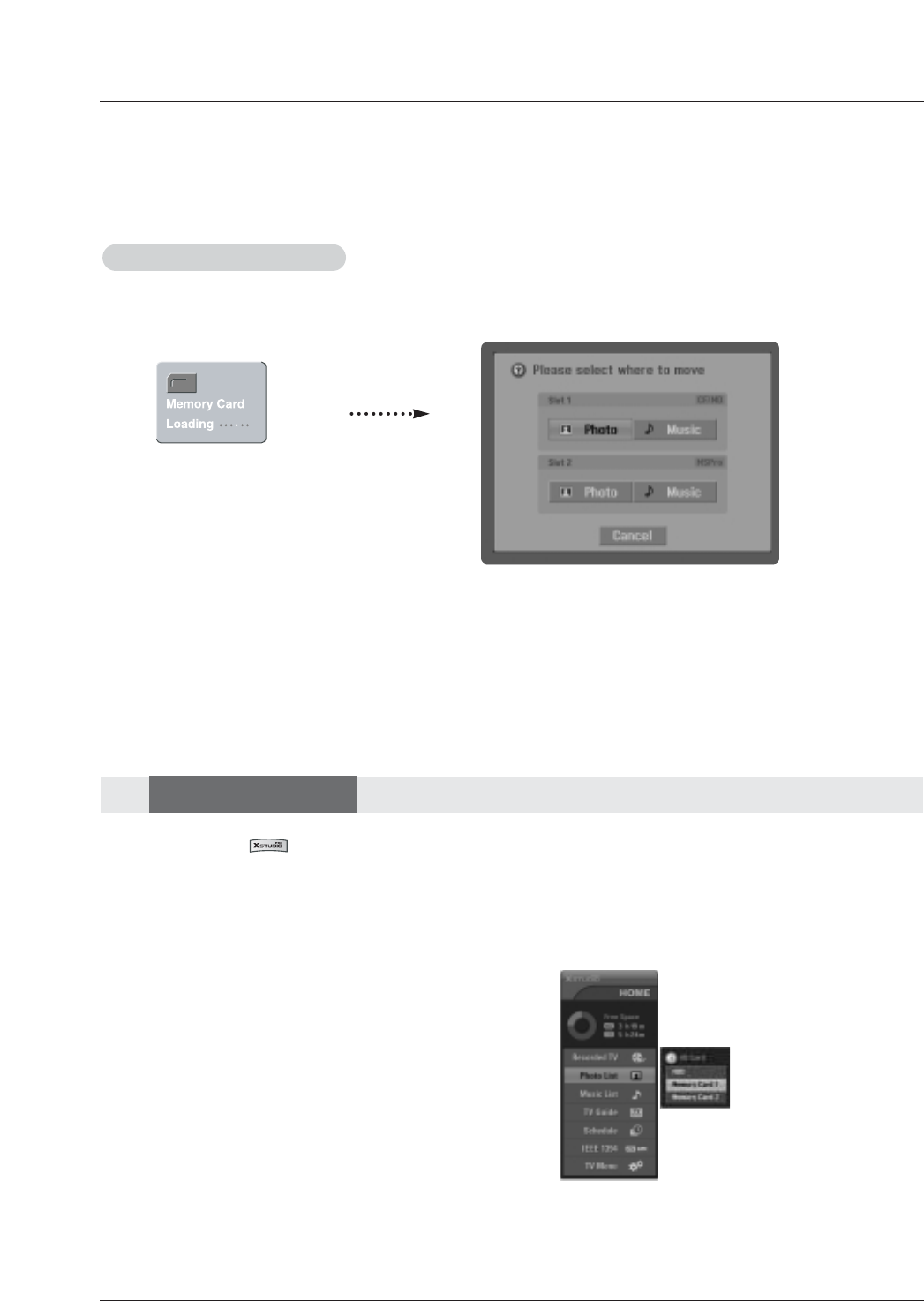
Owner’s Manual 65
Operation
1. In HOME menu, use D/Ebutton and then use the ENTER or
Gbutton to select the Photo List .
2. Use D/Ebutton to select the HDD/Memory Card 1/
Memory Card 2 and then you will see a screen filled with
thumbnail photos (pic.C,D).
A.
A.
-2.
Enter the HOME Menu
Enter the HOME Menu
- When you press the button, HOME menu is displayed.
It’s available to playback and copy the Photo file of Memory Card.or HDD.
The total storage space of photo file is 10GB.
- When you plug the Memory Card, this screen is displayed, automatically.
B.
B. C.
C.
1. Press the F/Gbutton to select Photo/Music.and use D/Ebutton to select Slot1 or Slot2.
2. Press ENTER button to move to Photo List/Music List of the each slot. (Directly move to p.59,(C))
Note: In 30 seconds later, 'Loading" message is disappeared.
Photo List
Photo List
Select the Photo or Music
Select the Photo or Music
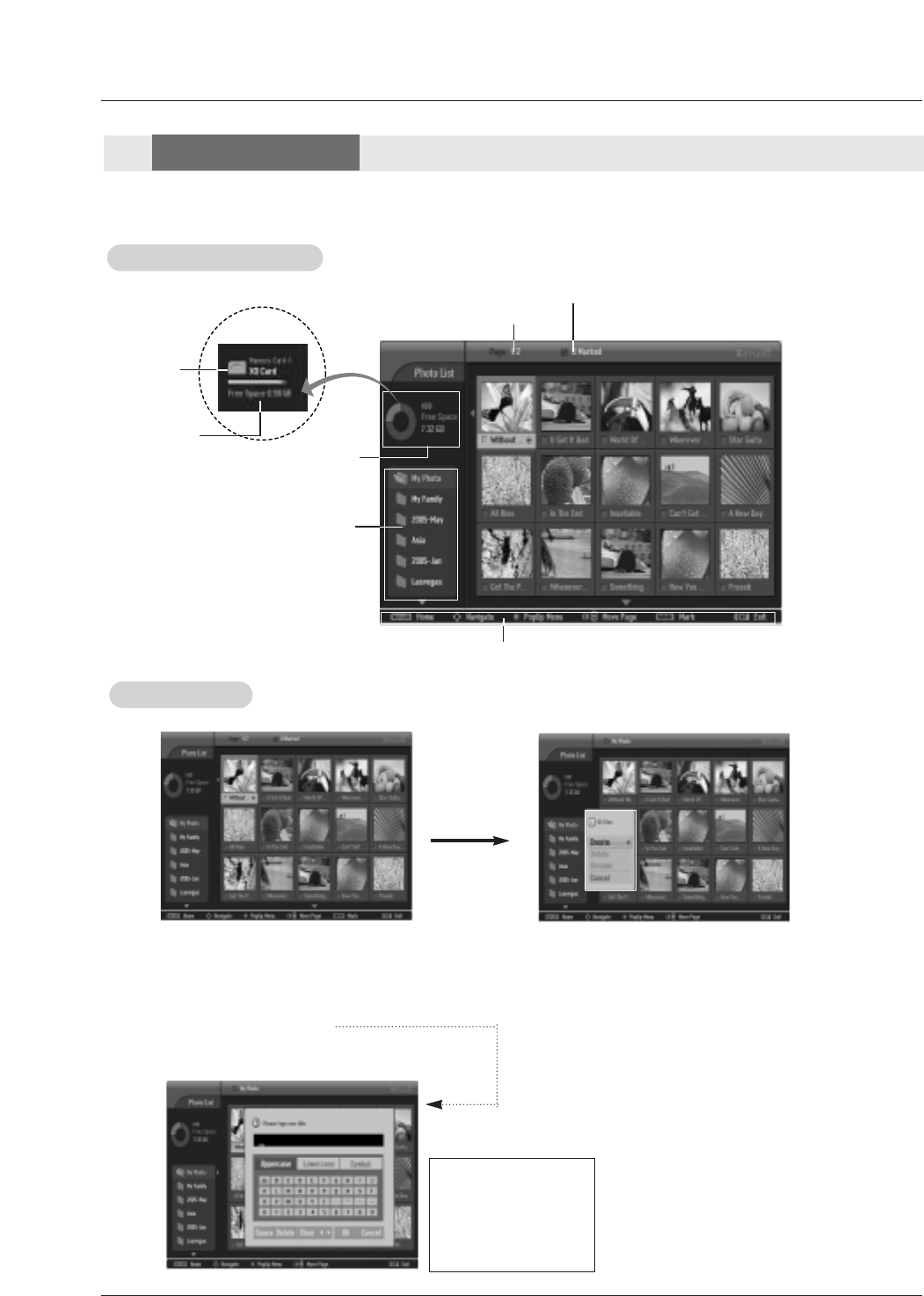
66 Plasma TV
Photo List
Photo List
Operation
C.
C.
3. Select the desired folder in the folder list and then press the ENTER button to view the detailed menu.
•Create:Create new folder.
•Delete:Delete folder (except ‘My Photo' )..
•Rename:Edit folder name.
•Cancel:Close the detailed menu.
D.
D.
-> Use the D/E/F/G
button to input the
wanted name.
-> And then select OK
and press the ENTER
button to save.
E.
E.
Screen Components
Screen Components
Usable HDD
Folder List
Current page/Total page
Marked thumbnail photo number
Direct Buttons
B.
B.
Usable Card
memory
Card type
Folder List
Folder List