LG Electronics USA UWB001 UWB Module TX User Manual Rocky2TFT display
LG Electronics USA UWB Module TX Rocky2TFT display
Users Manual
LGE Internal Use Only
UWB001 Module
User Manual

LGE Internal Use Only
Page 1-2 / 4
1 Module Diagram
1.1 Summary
- This chapter shows the structure of the UWB001 module separately.
1.2 UWB001 Module
- The UWB001 module can be represented by four blocks: MCU, Antenna, UWB Transceiver,
and Power.
MCU
- The MCU IC consists of RF(UWB) IC, debugging block, power supply block and Cortex M0,
which acts as a system core.
UWB Transceiver
- The role of UWB RF Block and Modem is handled by UWB Transceiver. The communication
signals are transmitted and received through one antenna
Antenna
- The Antenna is implemented as a pattern on main PCB. The antenna resonance is designed
according to 3.1 ~ 4.8GHz band.
Power
- A 3.3V Step-Up DC/DC Converter is applied to the module to convert the 3V (AAA Battery
2EA) to 3.3V which is a system power. In addition, a 1.8V step-down DC/DC converter is
applied to increase the efficiency of consumed current in RF operation.
LGE Internal Use Only
Page 2-3 / 4
2 Module Specification
2.1 Summary
- Specifications of the UWB001 module are defined.
2.2 UWB001 Module Hardware Specification
- The UWB module consists of MCU and UWB transceiver as remote distance measuring
sensor.
- The sytem power is supplied from the AAA battery.
- Programming interface
- The firmware download is done by connecting SWDIO, SWDCLK port and J-LINK, and the
module debugging is performed by UART connection
2.2.1 Dimension
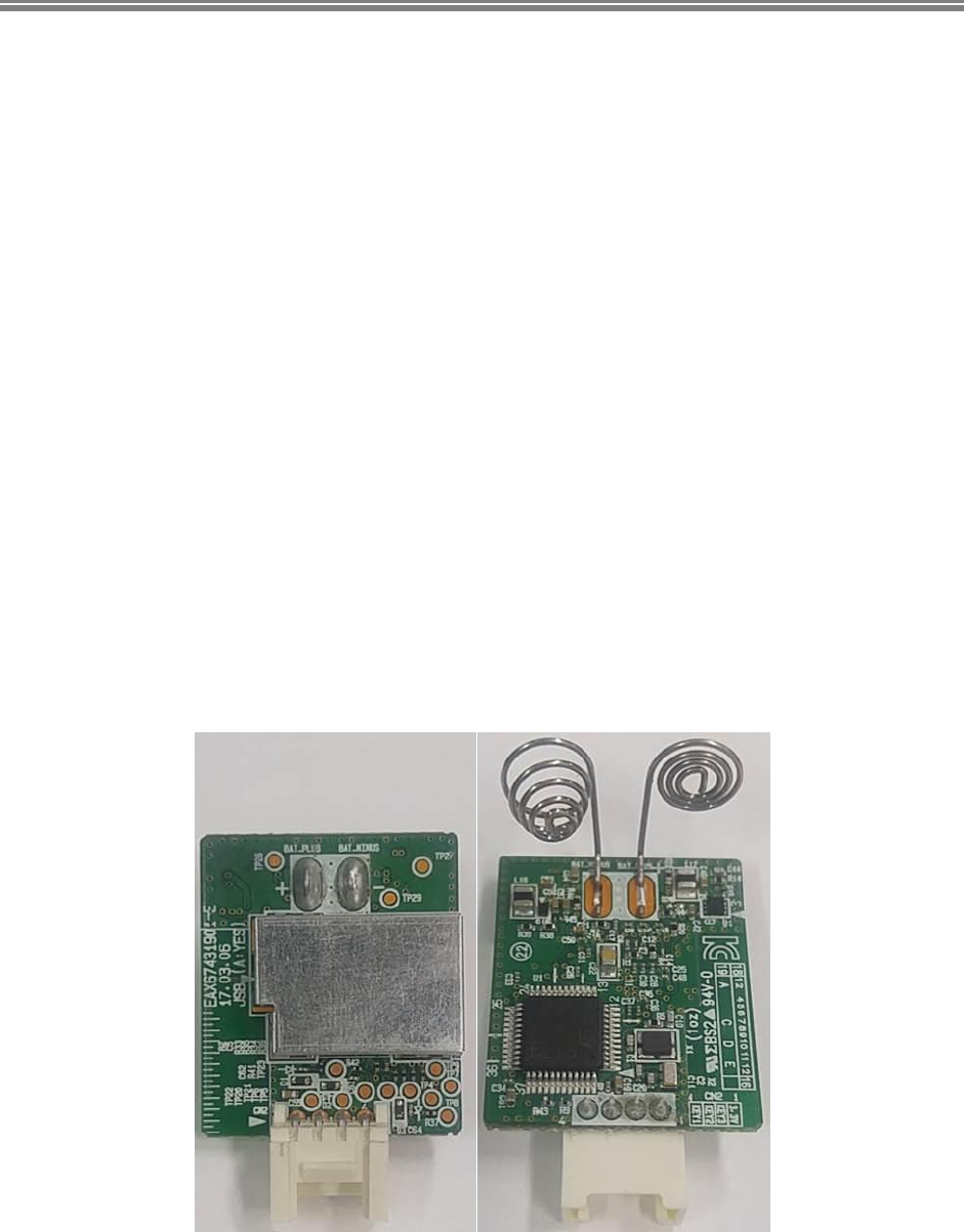
- The PCB Dimension is 23mm x 27mm and it is equipped with RF IC, MCU and DC/DC
Converter.
- PCB specification is 1.2mm 4 layer rigid PCB and through via
Picture. Module actual photo (Left: TOP, Right:BOTTOM)

LGE Internal Use Only
Page 2-4 / 4
FCC Information
This device complies with part 15 of the FCC Results. Operation is subject to the following
two conditions :
(1) This device may not cause harmful interface, and
(2) This device must accept any interference received, including interference that
may cause undesired operation.
Note: This equipment has been tested and found to comply with the limits for CLASS B digital device, pursuant
to Part 15 of FCC Rules. These limits are designed to provide reasonable protection against harmful interference
when the equipment is operated in a commercial environment This equipment generates, uses and can radiate
radio frequency energy and, if not installed and used in accordance with the instructions, may cause harmful
interference to radio communications. However, there is no guarantee that interference will not occur in a
particular installation. If this equipment does cause harmful interference to radio or television reception, which
can be determined by turning the equipment off and on, the user is encouraged to try correct the interference
by one or more of the following measures:
1.1. Reorient or relocate the receiving antenna.
1.2. Increase the separation between the equipment and receiver.
1.3. Connect the equipment into an outlet on a circuit different from that to which receiver is connected.
1.4. Consult the dealer or experienced radio/TV technician for help.
WARNING
Changes or modifications not expressly approved by the manufacturer could void the user’s
authority to operate the equipment.
End product labelling
The label for end product must include “Contains FCC ID: BEJUWB001”.
“CAUTION : Exposure to Radio Frequency Radiation.
This equipment complies with FCC radiation exposure limits set forth for an uncontrolled environment. This
equipment must be installed and operated with minimum distance of 20 cm between the radiator and your body.
This transmitter module is authorized only for use in device where the antenna may be installed such that 20 cm
may be maintained between the antenna and users.”