LG Electronics USA W1971SCT LCD MONITOR User Manual User s Manual H ok
LG Electronics USA LCD MONITOR User s Manual H ok
USERS MANUAL

EUT Type: LCD Monitor
FCC ID: BEJW1971SCT
Test Report No.: GETEC-E3-08-027
FCC Class B Certification
APPENDIX H
: USER’S MANUAL

Make sure to read the Important Precautions before using the product.
Keep the User's Guide(CD) in an accessible place for future reference.
See the label attached on the product and give the information to your
dealer when you ask for service.
W1971SC
W2271SC
W2271TC
User’s Guide
1
This unit has been engineered and manufactured to ensure your personal
safety, however improper use may result in potential electrical shock or fire
hazards. In order to allow the proper operation of all safeguards
incorporated in this display, observe the following basic rules for its
installation, use, and servicing.
On Safety
Use only the power cord supplied with the unit. In case you use another power
cord, make sure that it is certified by the applicable national standards if not being
provided by the supplier. If the power cable is faulty in any way, please contact the
manufacturer or the nearest authorized repair service provider for a replacement.
The power supply cord is used as the main disconnection device. Ensure that the
socket-outlet is easily accessible after installation.
Operate the display only from a power source indicated in the specifications of
this manual or listed on the display. If you are not sure what type of power supply
you have in your home, consult with your dealer.
Overloaded AC outlets and extension cords are dangerous. So are frayed power
cords and broken plugs. They may result in a shock or fire hazard. Call your service
technician for replacement.
Do not Open the Display:
There are no user serviceable components inside.
There are Dangerous High Voltages inside, even when the power is OFF.
Contact your dealer if the display is not operating properly.
To Avoid Personal Injury :
Do not place the display on a sloping shelf unless properly secured.
Use only a stand recommended by the manufacturer.
Do not drop an object on or apply impact to the product. Do not throw any toys
or objects on the product screen.
It can cause injury to human, problem to product and damage the display.
To Prevent Fire or Hazards:
Always turn the display OFF if you leave the room for more than a short period
of time. Never leave the display ON when leaving the house.
Keep children from dropping or pushing objects into the display's cabinet
openings. Some internal parts carry hazardous voltages.
Do not add accessories that have not been designed for this display.
When the display is to be left unattended for an extended period of time, unplug
it from the wall outlet.
In the presence of thunder and lightning, never press the power cord and signal
cable because it can be very dangerous. It can cause electric shock.
Important Precautions
2
Important Precautions
On Installation
Do not allow anything to rest upon or roll over the power cord, and do not place
the display where the power cord is subject to damage.
Do not use this display near water such as near a bathtub, washbowl, kitchen
sink, laundry tub, in a wet basement, or near a swimming pool.
Displays are provided with ventilation openings in the cabinet to allow the release
of heat generated during operation. If these openings are blocked, built-up heat
can cause failures which may result in a fire hazard. Therefore, NEVER:
Block the bottom ventilation slots by placing the display on a bed, sofa, rug, etc.
Place the display in a built-in enclosure unless proper ventilation is provided.
Cover the openings with cloth or other material.
Place the display near or over a radiator or heat source.
Do not rub or strike the Active Matrix LCD with anything hard as this may scratch,
mar, or damage the Active Matrix LCD permanently.
Do not press the LCD screen with your finger for a long time as this may cause
some afterimages.
Some dot defects may appear as Red, Green or Blue spots on the screen.
However, this will have no impact or effect on the display performance.
If possible, use the recommended resolution to obtain the best image quality for
your LCD display. If used under any mode except the recommended resolution,
some scaled or processed images may appear on the screen. However, this is
characteristic of the fixed-resolution LCD panel.
Leaving a fixed image on the screen for a long time may cause damage to the
screen and cause image burn-in. Make sure to use a screen saver on the product.
Burn-in and related problems are not covered by the warranty on this product.
On Cleaning
Unplug the display before cleaning the face of the display screen.
Use a slightly damp (not wet) cloth. Do not use an aerosol directly on the display
screen because over-spraying may cause electrical shock.
On Repacking
Do not throw away the carton and packing materials. They make an ideal
container in which to transport the unit. When shipping the unit to another
location, repack it in its original material.
On Disposal
The fluorescent lamp used in this product contains a small amount of mercury.
Do not dispose of this product with general household waste.
Disposal of this product must be carried out in accordance to the regulations of
your local authority.
3
Connecting the Display
IMPORTANT
This illustration depicts the general model of connection. Your monitor may differ from the items
shown in the picture.
Do not carry the product upside down holding only the stand base. The product may fall and get
damaged or injure your foot.
Before setting up the monitor, ensure that the power to the monitor, the computer
system, and other attached devices is turned off.
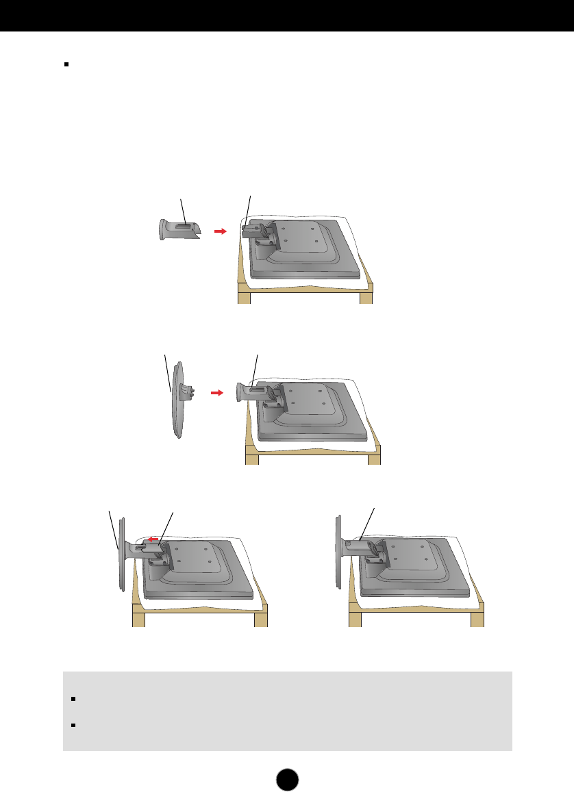
Connecting the stand
1.Place the monitor face down on the cushion or soft cloth.
2.Assemble the Stand Body into the product in the correct direction as shown in the picture.
3.Check the direction of the Stand Base and assemble it into the Stand Body.
5.Once assembled take the monitor up carefully and face the front side.
4.Insert the Cable Deco Cover in the Stand Body in the correct direction.
Stand Body
Stand Base
Stand Body Hinge Body
Stand Base Cable Deco Cover Cable Deco Cover
4
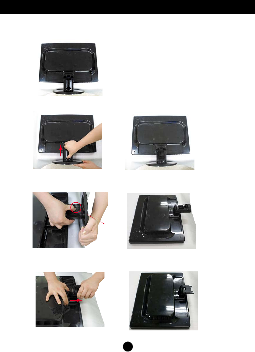
Connecting the Display
1.Place the monitor face down on the cushion or soft cloth.
3. Press the hook, take off the stand base from stand body.
4.
Please pull the stand body lightly to separate it from the hinge body.
2. Slide the Cable Deco Cover out from the stand body.
Hook
5
Connecting the Display
Before setting up the monitor, ensure that the power to the monitor, the computer
system, and other attached devices is turned off.
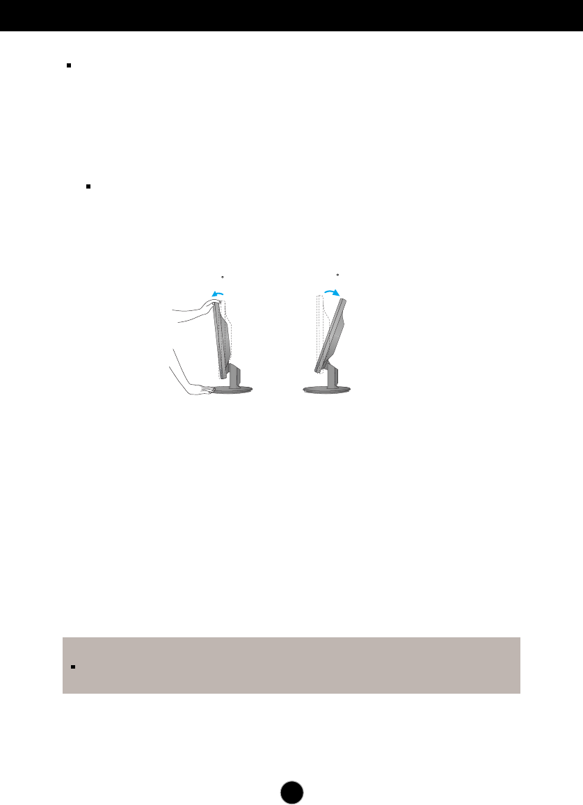
Positioning your display
1. Adjust the position of the panel in various ways for maximum comfort.
Tilt Range : -5˚~22˚
22
-5
ERGONOMIC
It is recommended that in order to maintain an ergonomic and comfortable
viewing position, the forward tilt angle of the monitor should not exceed 5 degrees.
6
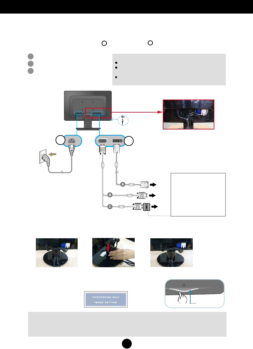
Connecting the Display W2271TC
A
B
C
Connect DVI Cable
Connect D-sub Cable (PC)
Connect D-sub Cable (Mac)
Using the Computer
1. Make sure to turn off the computer and product.
Connect signal input cable and power cord in order, then tighten the
screw of the signal cable.
12
NOTE
This is a simplified representation of the rear view.
This rear view represents a general model; your display may differ
from the view as shown.
User must use shielded signal interface cables (D-sub 15 pin cable, DVI
cable) with ferrite cores to maintain standard compliance for the product.
Wall-outlet type
MAC
Power Cord
1
2
Mac adapter
For Apple Macintosh use, a
separate plug adapter is needed
to change the 15 pin high density
(3 row) D-sub VGA connector on
the supplied cable to a 15 pin 2
row connector.
PC
PC
Signal Cable
DVI (This feature is not
available in all countries.)
Fix the power cord & signal
cable as shown in the picture.
Headphone/Earphone Input
Varies according to model.
3. Press the power button on the front panel to turn the power
on. When monitor power is turned on, the 'Self Image
Setting Function' is executed automatically.
(Only Analog Mode)
NOTE
‘ Self Image Setting Function’? This function provides the user with optimal display settings.When the user connects the
monitor for the first time, this function automatically adjusts the display to optimal settings for individual input signals.
‘AUTO/SET’ Function? When you encounter problems such as blurry screen, blurred letters, screen flicker or tilted screen
while using the device or after changing screen resolution, press the AUTO/SET function button to improve resolution.
2. Insert the Cable Deco Cover in the Stand Body in the correct direction.
Power Button
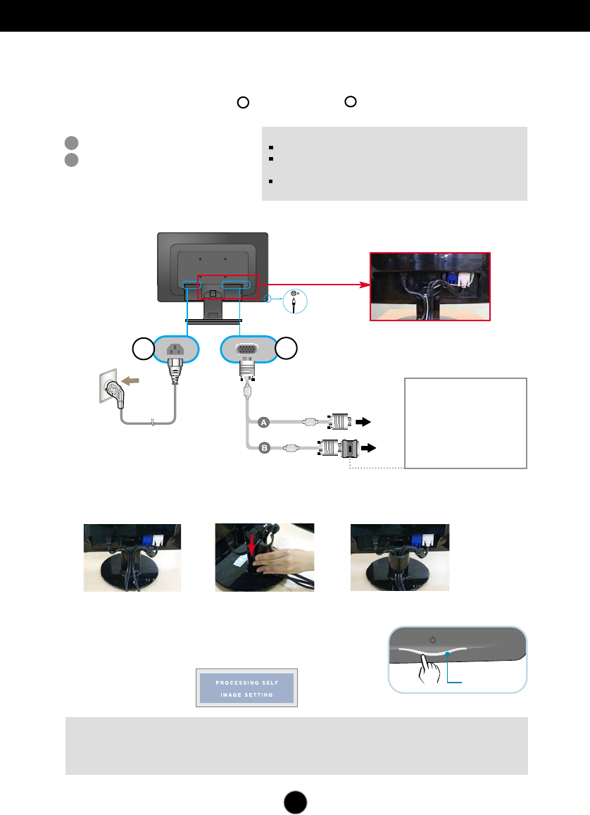
Connecting the Display W1971SC/W2271SC
7
A
B
Connect D-sub Cable (PC)
Connect D-sub Cable (Mac)
Using the Computer
1. Make sure to turn off the computer and product.
Connect signal input cable and power cord in order, then tighten the
screw of the signal cable.
12
NOTE
This is a simplified representation of the rear view.
This rear view represents a general model; your display may differ
from the view as shown.
User must use shielded signal interface cables (D-sub 15 pin cable, DVI
cable) with ferrite cores to maintain standard compliance for the product.
Varies according to model.
3. Press the power button on the front panel to turn the power
on. When monitor power is turned on, the 'Self Image
Setting Function' is executed automatically.
NOTE
‘ Self Image Setting Function’? This function provides the user with optimal display settings.When the user connects the
monitor for the first time, this function automatically adjusts the display to optimal settings for individual input signals.
‘AUTO/SET’ Function? When you encounter problems such as blurry screen, blurred letters, screen flicker or tilted screen
while using the device or after changing screen resolution, press the AUTO/SET function button to improve resolution.
2. Insert the Cable Deco Cover in the Stand Body in the correct direction.
Power Button
Wall-outlet type
MAC
Power Cord
1
2
Mac adapter
For Apple Macintosh use, a
separate plug adapter is
needed to change the 15 pin
high density (3 row) D-sub VGA
connector on the supplied cable
to a 15 pin 2 row connector.
PC
Signal Cable
Fix the power cord & signal cable
as shown in the picture.
Headphone/Earphone Input
8
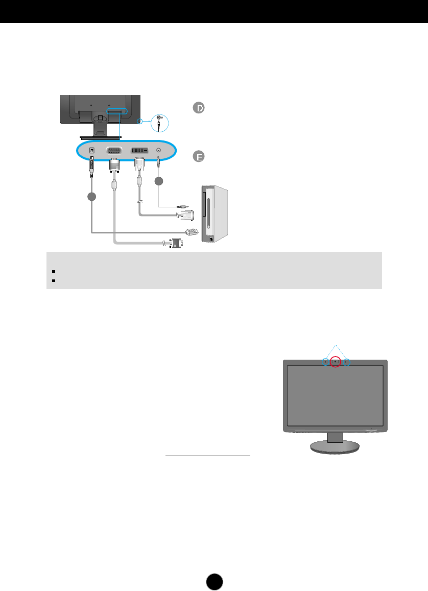
Using Webcam Function
Connecting the USB(Universal Serial Bus) Cable
NOTE
For more information on USB, visit the following web site.(http://www.usb.org)
With the USB cable unconnected, you will not have any trouble using the PC.
D
E
1. You can use the monitor’s webcam function by connecting the monitor and the PC with
USB cable.
Connect USB cable
USB Upstream port (1 unit): Connect it with the
downstream port of the PC or laptop.
(Your computer must support USB.)
Connect audio cable
1. To use the webcam function, connect the USB cable and install the programs on
the webcam software CD.
2. The webcam software CD contains two programs.
Install the LG Webcam Viewer program first, and then the LG Webcam Driver files.
3. For more information about the programs, refer to the user guide in the webcam
software CD.
■
Minimum system requirements
· Intel Pentium 4 1.6 GHz or AMD® equivalent processor
· Microsoft®Windows®XP Service Pack 2 (SP2)/ XP 64-bit/
Vista 32-bit / Vista 64-bit
·
256MB RAM or higher (512MB RAM recommended)
·
500MB HDD
·
CD-ROM
·
USB 2.0 interface
·
Window Vista Premium / XP SP2 with UVC patch
■Please update UVC patch from http://www.microsoft.com before use.
Webcam
Microphones
To use the webcam function, your PC should meet the following minimum system requirements.
Using the Webcam function
9
Control Panel Functions
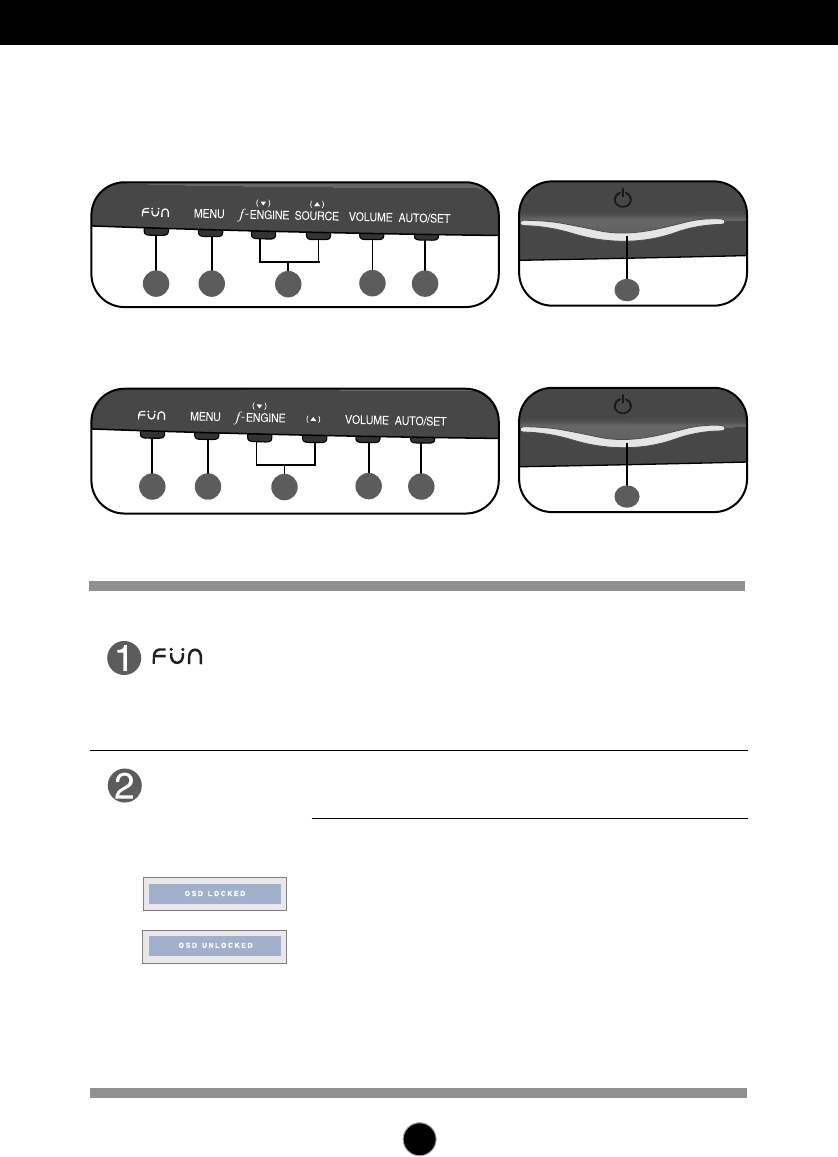
Front Panel Controls
Use this button to enter EZ ZOOMING,4:3 IN WIDE,
PHOTO EFFECT items.
For more information, refer to page 20.
MENU Button
Use this button to enter or exit from the On Screen Display.
OSD LOCKED/UNLOCKED
This function allows you to lock the current control settings, so
that these settings are not inadvertently changed. To lock the
OSD settings, press and hold the MENU button for several
seconds. The message "OSD LOCKED" appears.
You can unlock the OSD settings at any time by pushing
the MENU button for several seconds. The message
"OSD UNLOCKED" appears.
Button
12 5
34
6
W2271SC
12 5
34
6
W2271TC
10
Control Panel Functions
Use this button to turn the display on or off.
This Indicator lights up blue when the display operates
normally(On Mode). If the display is in Sleep Mode
(Energy Saving), this indicator color changes
to amber.
Power Button
(Power Indicator)
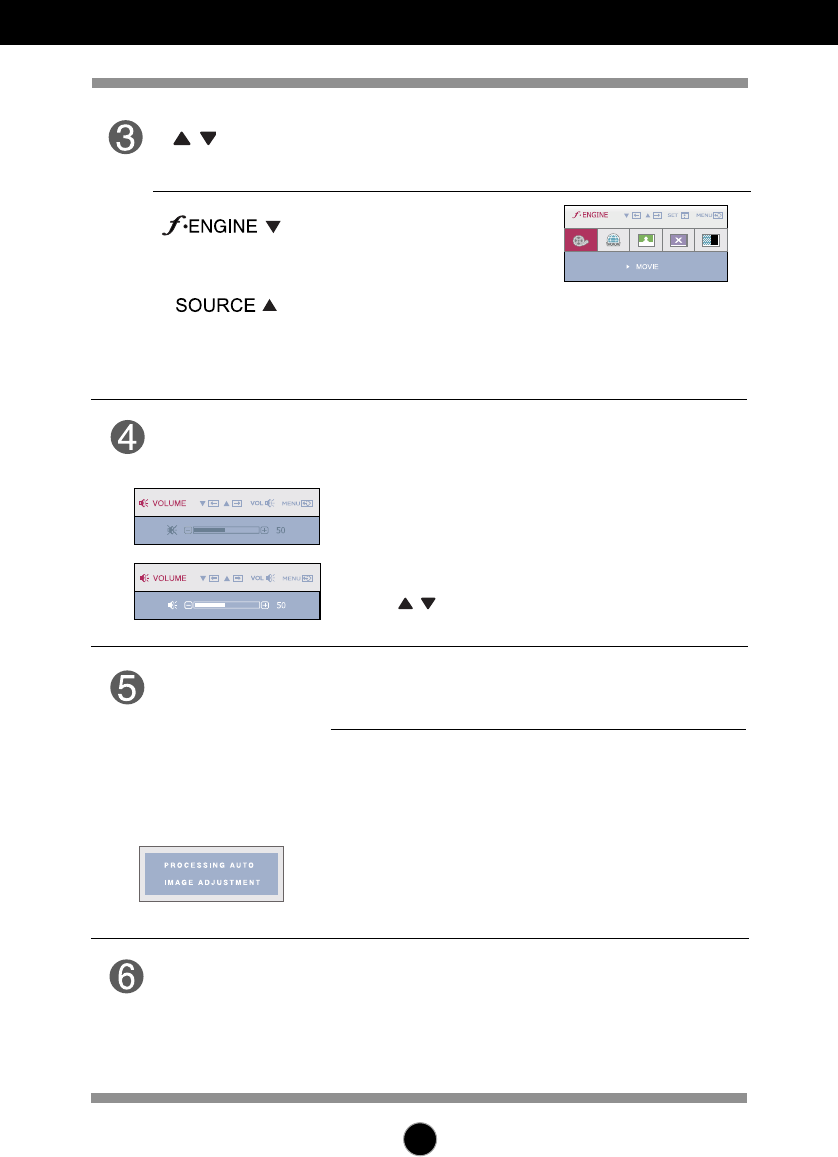
Use this button to enter a selection in the On Screen
Display.
AUTO/SET
Button
AUTO IMAGE ADJUSTMENT
When adjusting your display settings, always press
the AUTO/SET button before entering the On Screen
Display(OSD). This will automatically adjust your
display image to the ideal settings for the current
screen resolution size (display mode).
The best display mode is
1680 x 1050
Buttons
Use these buttons to select or adjust functions in the On
Screen Display.
For more information,
refer to page 21.
Use this button to make either D-Sub or DVI connector
active. This feature is used when two computers are
connected to the display. The default setting is D-Sub.
(Only W2271TC )
(SOURCE Hot key)
Use the buttons to adjust the speaker volume.
<MUTE OFF>
<MUTE ON>
Use this button to mute or adjust the sound volume.
VOLUME
Button
Control Panel Functions
11
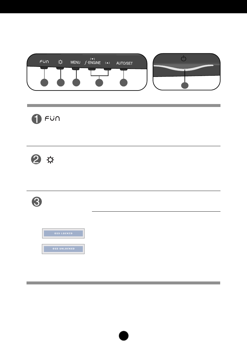
Use this button to enter EZ ZOOMING,4:3 IN WIDE,
PHOTO EFFECT items.
For more information, refer to page 20.
Button
Use this button to enter On Screen Display Sub-menu to
adjust BRIGHTNESS directly.
MENU Button
Use this button to enter or exit from the On Screen Display.
OSD LOCKED/UNLOCKED
This function allows you to lock the current control settings, so
that these settings are not inadvertently changed. To lock the
OSD settings, press and hold the MENU button for several
seconds. The message "OSD LOCKED" appears.
You can unlock the OSD settings at any time by pushing
the MENU button for several seconds. The message
"OSD UNLOCKED" appears.
Button
Front Panel Controls
W1971SC
12 5
4
3
6
12
Control Panel Functions
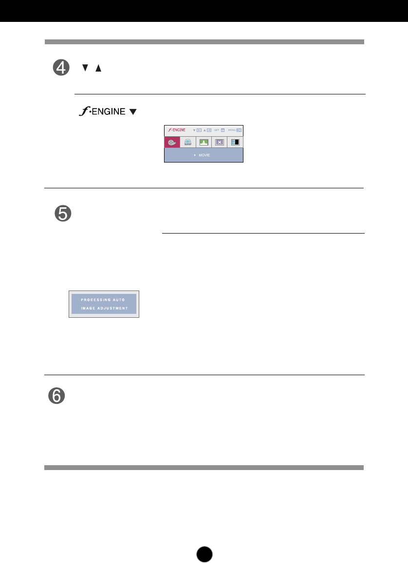
Use this button to enter a selection in the On Screen
Display.
AUTO/SET
Button
AUTO IMAGE ADJUSTMENT
When adjusting your display settings, always press
the AUTO/SET button before entering the On Screen
Display(OSD). This will automatically adjust your
display image to the ideal settings for the current
screen resolution size (display mode).
The best display mode is
1440 x 900
Buttons
Use these buttons to select or adjust functions in the On
Screen Display.
For more information, refer to page 21.
Use this button to turn the display on or off.
This Indicator lights up blue when the display operates
normally(On Mode). If the display is in Sleep Mode
(Energy Saving), this indicator color changes
to amber.
Power Button
(Power Indicator)
13
On Screen Display (OSD) Control Adjustment
Screen Adjustment
Making adjustments to the image size, position and operating parameters of
the display is quick and easy with the On Screen Display Control system.
A short example is given below to familiarize you with the use of the controls.
The following section is an outline of the available adjustments and selections
you can make using the OSD.
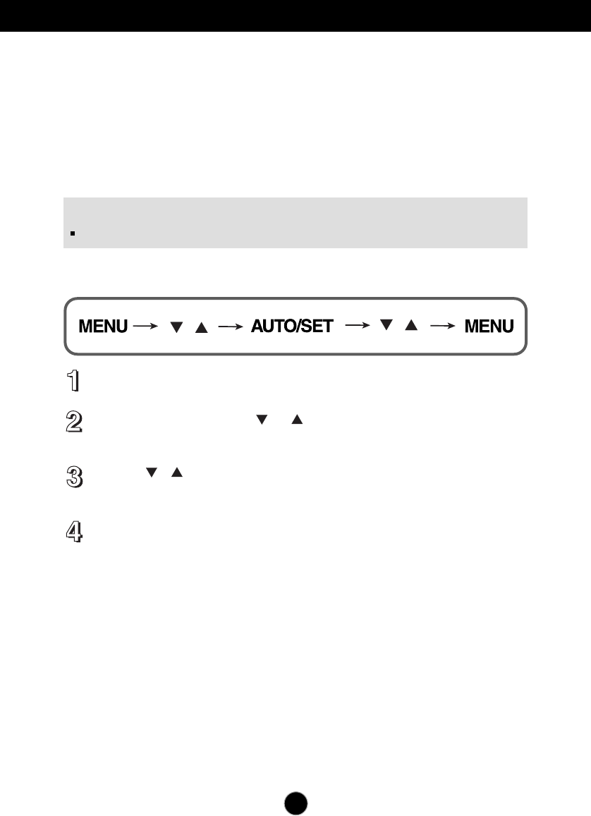
To make adjustments in the On Screen Display, follow these steps:
Press the MENU Button, then the main menu of the OSD appears.
To access a control, use the or Buttons. When the icon you want
becomes highlighted, press the AUTO/SET Button.
Use the / Buttons to adjust the image to the desired level. Use the
AUTO/SET Button to select other sub-menu items.
Press the MENU Button once to return to the main menu to select another
function. Press the MENU Button twice to exit from the OSD.
NOTE
Allow the display to stabilize for at least 30 minutes before making image adjustments.
14
NOTE
The order of icons may differ depending on the model (14~22).
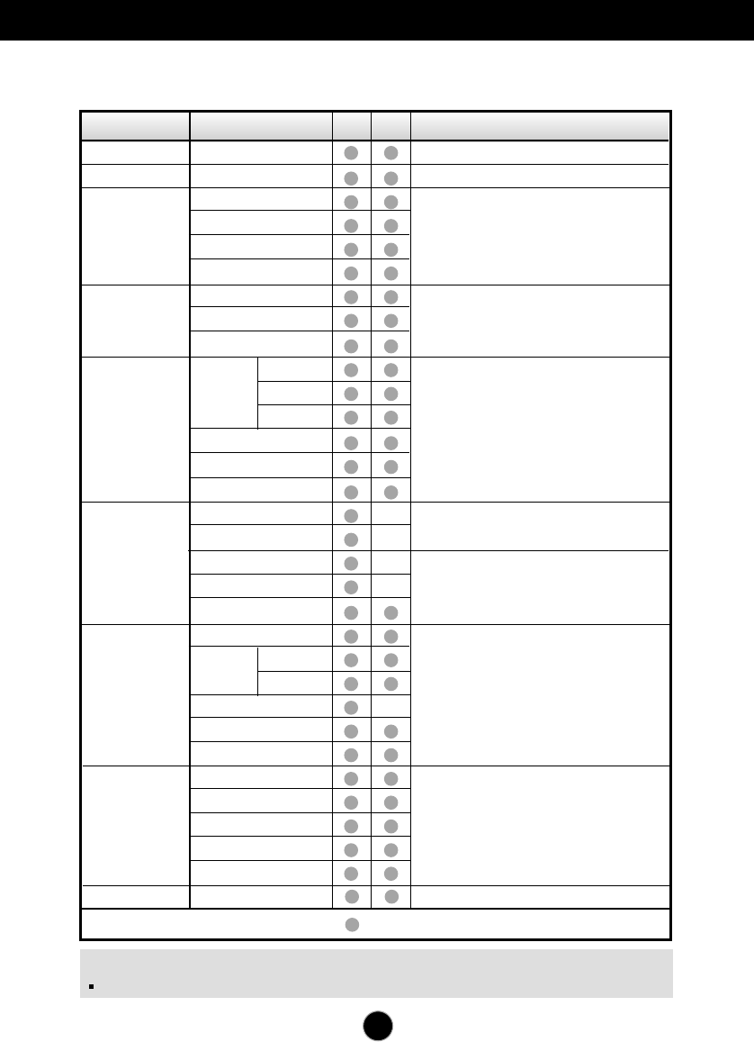
On Screen Display(OSD) Selection and Adjustment W2271TC
The following table indicates all the On Screen Display control, adjustment, and
setting menus.
Main menu Sub-menu A D Reference
EZ ZOOMING
4:3 IN WIDE
PHOTO
EFFECT
PICTURE
COLOR
TRACKING
SETUP
FLATRON
F-ENGINE
VOLUME
NORMAL
GAUSSIAN BLUR
SEPIA
MONOCHROME
BRIGHTNESS
CONTRAST
GAMMA
PRESET
sRGB
6500K
9300K
RED
GREEN
BLUE
HORIZONTAL
VERTICAL
CLOCK
PHASE
SHARPNESS
LANGUAGE
WHITE BALANCE
POWER INDICATOR
FACTORY RESET
OSD
POSITION
HORIZONTAL
VERTICAL
MOVIE
INTERNET
USER
NORMAL
DEMO
To adjust the resolution
To adjust the image size
To adjust the screen color mode
To adjust the brightness, contrast
and gamma of the screen
To customize the color of the screen
To adjust the position of the screen
To customize the screen status for a
user's operating environment
To select or customize desired
image settings
: Adjustable A : Analog Input D : Digital Input
To improve the clarity and stability of
the screen
To adjust or turn off the sound
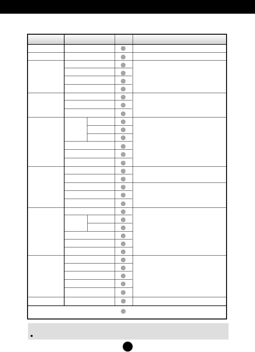
On Screen Display(OSD) Selection and Adjustment
W1971SC/W2271SC
15
NOTE
The order of icons may differ depending on the model (15~22).
The following table indicates all the On Screen Display control, adjustment, and
setting menus.
Main menu Sub-menu A Reference
EZ ZOOMING
4:3 IN WIDE
PHOTO
EFFECT
PICTURE
COLOR
TRACKING
SETUP
FLATRON
F-ENGINE
VOLUME
NORMAL
GAUSSIAN BLUR
SEPIA
MONOCHROME
BRIGHTNESS
CONTRAST
GAMMA
PRESET
sRGB
6500K
9300K
RED
GREEN
BLUE
HORIZONTAL
VERTICAL
CLOCK
PHASE
SHARPNESS
LANGUAGE
WHITE BALANCE
POWER INDICATOR
FACTORY RESET
OSD
POSITION
HORIZONTAL
VERTICAL
MOVIE
INTERNET
USER
NORMAL
DEMO
To adjust the resolution
To adjust the image size
To adjust the screen color mode
To adjust the brightness, contrast
and gamma of the screen
To customize the color of the screen
To adjust the position of the screen
To customize the screen status for a
user's operating environment
To select or customize desired
image settings
: Adjustable A : Analog Input
To improve the clarity and stability of
the screen
To adjust or turn off the sound (Only W2271SC)
16
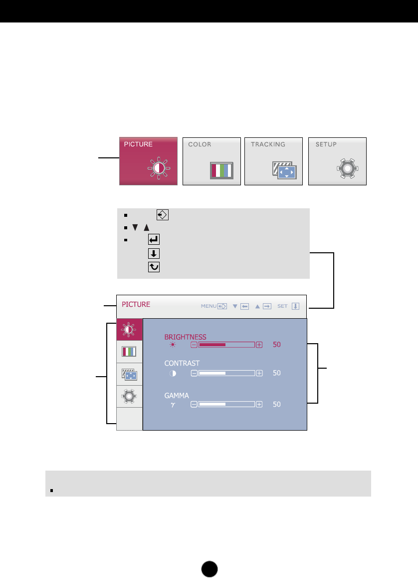
On Screen Display(OSD) Selection and Adjustment
You were introduced to the procedure of selecting and adjusting an item
using the OSD system. Listed below are the icons, icon names, and icon
descriptions of the all items shown on the Menu.
Press the MENU Button, then the main menu of the OSD appears.
Sub-menus
NOTE
OSD (On Screen Display) menu languages on the monitor may differ from the manual.
Menu Name
Icons
Main Menu
Button Tip
MENU : Exit
: Adjust (Decrease/Increase)
SET : Enter
: Select another sub-menu
: Restart to select sub-menu
17
On Screen Display(OSD) Selection and Adjustment
The OSD screen will appear when you press the button on the front
of the monitor.
Main menu Description
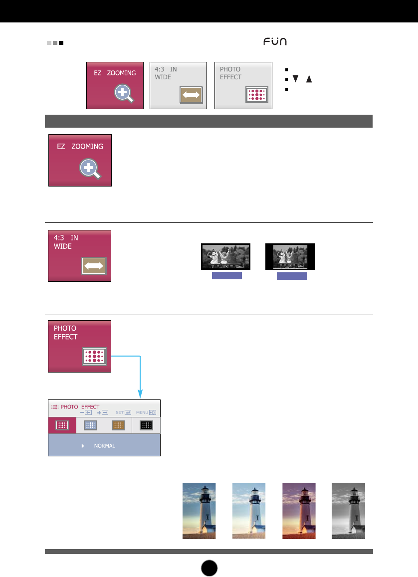
EZ ZOOMING To select the display resolution.
At the current display, use 'AUTO/SET' button to
select 'EZ ZOOMING', then the display resolution
is transferred to the one step low resolution.
Select 'EZ ZOOMING' one more, the display is
back to the original display.
* This function is operated only if the 'forteManag-
er' is installed to PC.
MENU : Exit
, : Move
SET : Select
4:3 IN WIDE To select the image size of the screen.
•WIDE : Switch to full screen mode according to
input image signal.
•4:3 : Change the input image signal ratio to 4:3.
WIDE 4:3
PHOTO
EFFECT
To select the color of the screen.
•NORMAL
The PhotoEffect function is disabled.
•GAUSSIAN BLUR
This option is to add the effect to the screen that
the dark and sharp image becomes brighter
and more blurred.
•SEPIA
This option changes the screen to be Sepia
tone. The Sepia tone is brown color tone.
•MONOCHROME
This option changed the screen to be Gray
tone. The screen image is displayed with just
white, black, gray colors.
Use the AUTO/SET button
to go to sub-menu.
MONOCHROME
NORMAL GAUSSIAN BLUR SEPIA
18
On Screen Display(OSD) Selection and Adjustment
Main menu Sub menu Description
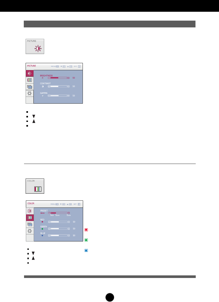
PICTURE
MENU : Exit
: Decrease
: Increase
SET : Select another sub-menu
BRIGHTNESS
CONTRAST
GAMMA
To adjust the brightness of the screen.
To adjust the contrast of the screen.
Set your own gamma value. : -50 / 0 / 50
On the monitor, high gamma values
display whitish images and low gamma
values display high contrast images.
PRESET
RED
GREEN
BLUE
Select the screen color.
• sRGB: Set the screen color to fit the
sRGB standard color
specification.
• 6500K: Slightly reddish white.
• 9300K: Slightly bluish white.
Set your own red color levels.
Set your own green color levels.
Set your own blue color levels.
COLOR
MENU : Exit
: Decrease
: Increase
SET : Select another sub-menu
19
On Screen Display(OSD) Selection and Adjustment
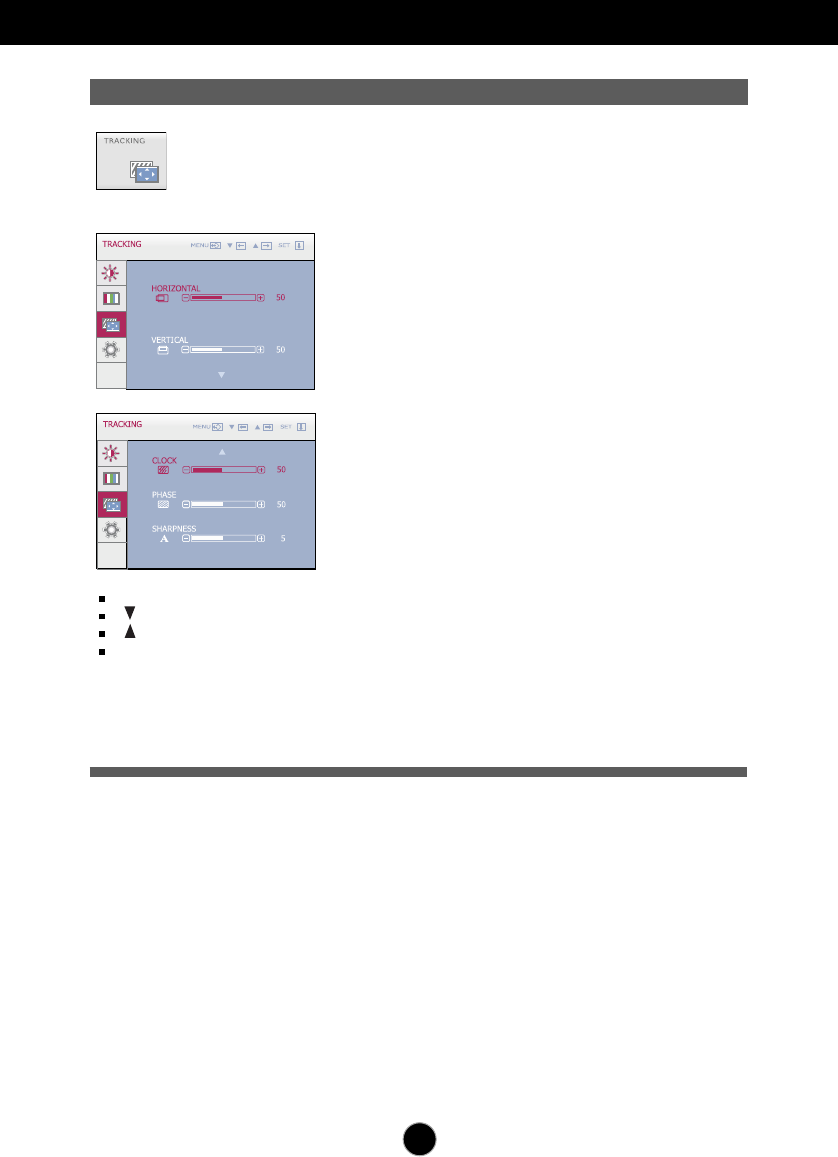
TRACKING
Main menu Sub menu Description
MENU : Exit
: Decrease
: Increase
SET : Select another sub-menu
CLOCK
PHASE
SHARPNESS
To minimize any vertical bars or
stripes visible on the screen
background.
The horizontal screen size will also
change.
To adjust the focus of the display.
This item allows you to remove any
horizontal noise and clear or sharpen
the image of characters.
To adjust the clearness of the screen.
HORIZONTAL
VERTICAL
To move image left and right.
To move image up and down.
20
On Screen Display(OSD) Selection and Adjustment
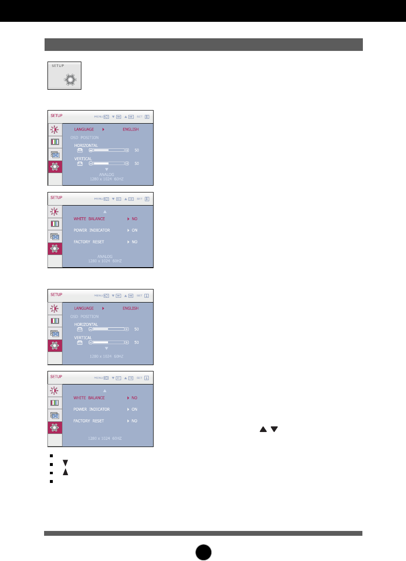
Press the , buttons to reset immediately.
If this does not improve the screen image, restore the factory default settings. If necessary,
perform the white balance function again. This function will be enabled only when the input
signal is an analog signal.
SETUP
MENU : Exit
: Adjust
: Adjust
SET : Select another
sub-menu
Main menu Sub menu Description
To choose the language in which the
control names are displayed.
To adjust position of the OSD window
on the screen.
LANGUAGE
OSD
POSITION
WHITE
BALANCE
If the output of the video card is
different the required specifications,
the color level may deteriorate due
to video signal distortion. Using this
function, the signal level is adjusted
to fit into the standard output level of
the video card in order to provide the
optimal image.
Activate this function when white
and black colors are present in the
screen.
Restore all factory default settings except
"LANGUAGE."
FACTORY
RESET
POWER
INDICATOR
Use this function to set the power
indicator on the front side of the monitor
to ON or OFF.
If you set OFF, it will go off.
If you set ON at any time, the power
indicator will automatically be turned on.
W2271TC
W1971SC/W2271SC
21
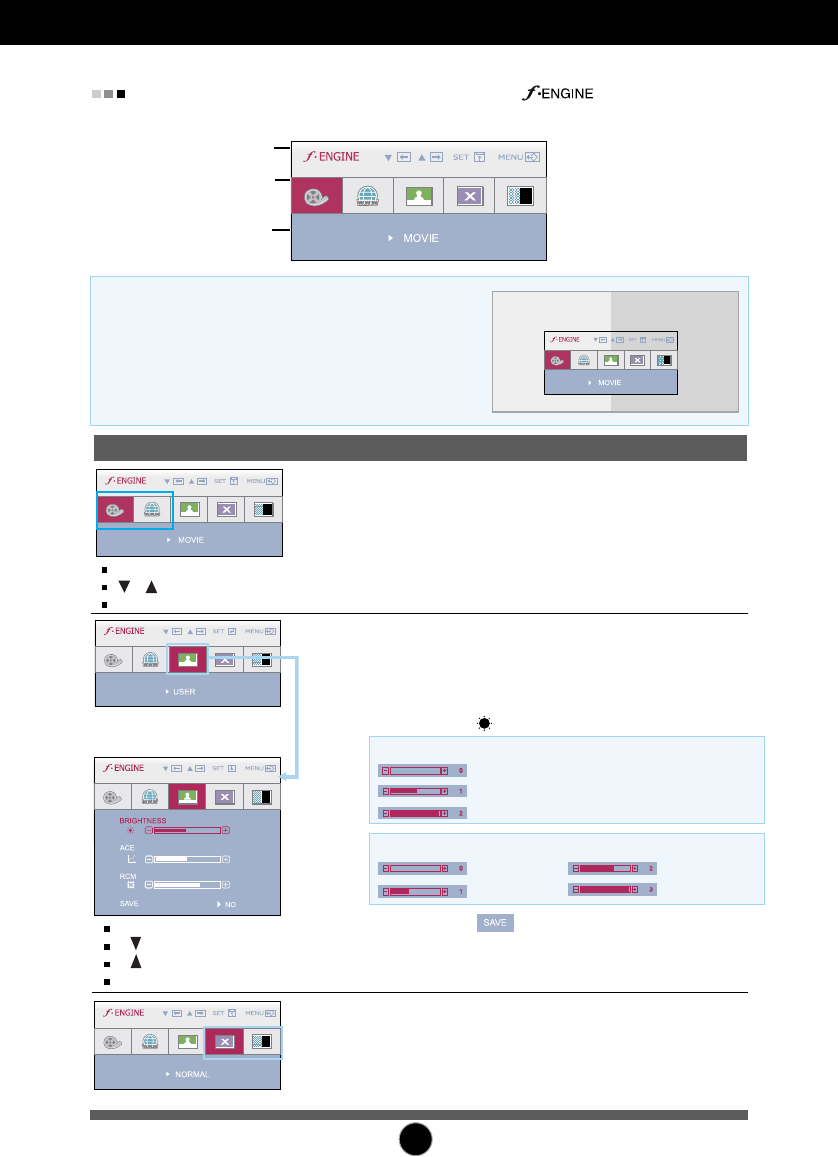
On Screen Display(OSD) Selection and Adjustment
Icons
Menu Name
Sub-menu Name
Main menu Sub menu Description
To adjust the USER sub-menu
function, press the SET Button
MOVIE
TEXT
NORMAL
DEMO
50
1
2
USER
When you execute F-ENGINE, two tones will appear
on the screen as shown. The applied screen will
appear on the left side, whereas the non-applied
screen will appear on the right side. Press the SET
button to use the adjusted screen.
FLATRON F-ENGINE
Screen when applied Screen when not applied
The OSD screen will appear when you press the button on the
front of the monitor.
Select 'YES' in sub-menu to save adjustments.
This is under normal operating conditions.
* Normal mode is when f-ENGINE is turned off.
This feature lets you easily select the best desired
image condition optimized to the environment
(ambient illumination, image types etc).
MOVIE
: For animation images in videos or movies
TEXT
: For text images (Word processing etc.)
USER
You can manually adjust brightness, ACE or RCM.
You can save or restore the adjusted value even
when using a different environment.
Not applied
Green enhance
MENU : Exit
, : Move
SET : Select
MENU : Exit
: Decrease
: Increase
SET : Select another sub-menu
Flesh tone
Color Enhance
...
BRIGHTNESS
( ) : Adjusts screen brightness.
...
ACE
(Adaptive Clarity Enhancer)
: Selects the clarity mode.
Not applied
Weak clarity and luminosity contrast.
Strong clarity and luminosity contrast.
...
RCM(Real Color Management): Selects the color mode.
This is just for advertising to customer in the shops. It's
setting is same with Movie mode and screen is divided
by half.
22
Troubleshooting
No image appears
Check the following before calling for service.
No image appears
Do you see a "OSD LOCKED" message on the screen?
●Is the power cord of the
display connected?
●Is the power indicator
light on?
●Is the power on and the
power indicator blue or
green?
●Is the power indicator
amber?
●Do you see an "OUT OF
RANGE" message on
the screen?
●Do you see a "CHECK
SIGNAL CABLE"
message on the
screen?
•
Check and see if the power cord is connected
properly to the power outlet.
• Press
the Power button.
•
Adjust the brightness and the contrast.
•
If the display is in power saving mode, try moving
the mouse or pressing any key on the keyboard to
bring up the screen.
• Try to turn on the PC
.
•
This message appears when the signal from the
PC (video card) is out of horizontal or vertical
frequency range of the display. See the
'Specifications' section of this manual and
configure your display again.
•
This message appears when the signal cable
between your PC and your display is not
connected. Check the signal cable and try again.
• You can secure the current control settings,
so that they cannot be inadvertently changed.
You can unlock the OSD controls at any time
by pushing the MENU button for several
seconds: the message
“OSD UNLOCKED” will appear.
●
Do you see “OSD
LOCKED” when you
push MENU button?
23
Troubleshooting
Display image is incorrect
●Display Position is
incorrect.
●On the screen
background, vertical
bars or stripes are
visible.
●Any horizontal noise
appearing in any
image or characters
are not clearly
portrayed.
•
Press the AUTO/SET button to automatically
adjust your display image to the ideal setting.
If the results are unsatisfactory, adjust the image
position using the H position and V position icon
in the on screen display.
•
Press the AUTO/SET button to automatically
adjust your display image to the ideal setting.
If the results are unsatisfactory, decrease the
vertical bars or stripes using the CLOCK icon in
the on screen display.
•
Press the AUTO/SET button to automatically
adjust your display image to the ideal setting.
If the results are unsatisfactory, decrease the
horizontal bars using the PHASE icon in the on
screen display.
•
Check Control Panel --> Display --> Settings
and adjust the display to the recommended
resolution or adjust the display image to the ideal
setting. Set the color setting higher than 24 bits
(true color).
Important
Check Control Panel --> Display --> Settings and see if the frequency or the
resolution were changed. If yes, readjust the video card to the recommend
resolution.
Reasons for Recommending Optimal Resolution : The aspect ratio is 16:10.
If the input resolution is not 16:10 (for instance, 16:9, 5:4, 4:3), you might encounter
problems such as blurred letters, blurry screen, cut-off screen display or tilted
screen.
The setting method can differ by computer and O/S (Operation System),
and resolution mentioned above may not be supported by the video card
performance. In this case, please ask to the computer or the video card
manufacturer.
24
Troubleshooting
Have you installed the display driver?
●
Have you installed the
display driver?
●
Do you see an
"Unrecognized monitor,
Plug&Play (VESA DDC)
monitor found"
message?
•
Be sure to install the display driver from the display
driver CD (or diskette) that comes with your
display. Or, you can also download the driver from
our web site: http://www.lge.com.
•
Make sure to check if the video card supports
Plug&Play function.
Display image is incorrect
●The screen color is
mono or abnormal.
●The screen blinks.
•
Check if the signal cable is properly connected
and use a screwdriver to fasten if necessary.
•
Make sure the video card is properly inserted in
the slot.
•
Set the color setting higher than 24 bits (true color)
at Control Panel - Settings.
•
Check if the screen is set to interlace mode and if
yes, change it to the recommend resolution.

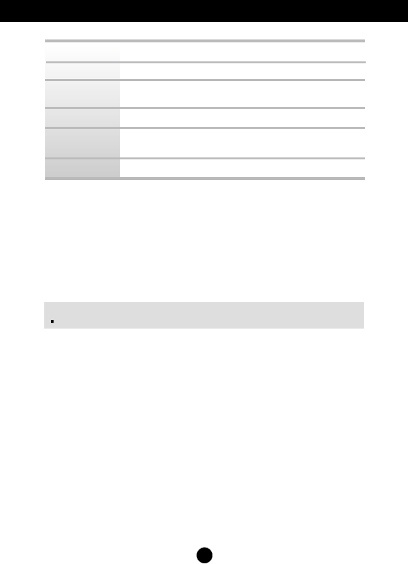
Specifications W1971SC
25
Display
Sync Input
Video Input
Resolution
Plug&Play
Power
Consumption
Dimensions
&Weight
Range
Power Input
Environmental
Conditions
19 inches (48.14 cm) Flat Panel Active matrix-TFT LCD
Anti-Glare coating
Visible diagonal size : 48.14 cm
0.285 mm pixel pitch
Horizontal Freq. 28 - 83 kHz (Automatic)
Vertical Freq. 56 - 75 Hz (Automatic)
Input Form Separate Sync.
SOG (Sync On Green)
Signal Input 15 pin D-Sub Connector
Input Form RGB Analog (0.7 Vp-p/ 75 ohm)
Max VESA 1440 x 900 @75Hz
Recommend VESA 1440 x 900 @60 Hz
DDC 2B
On Mod :
34W(Typ.)
Sleep Mode ≤1 W
Off Mode ≤1 W
With Stand Without Stand
Width
44.78 cm / 17.63 inches 44.78 cm / 17.63 inches
Height
38.63 cm / 15.21 inches 31.84 cm / 12.54 inches
Depth
22.07 cm / 8.69 inches 5.66 cm / 2.23 inches
Weight(excl. packing) 3.99 kg (8.79 lbs)
Tilt -5˚~22˚
AC 100-240V~ 50/60Hz 0.8A
Operating Conditions
Temperature 10˚C to 35 ˚C
Humidity 10 % to 80 % non-Condensing
Storage Conditions
Temperature -20˚C to 60 ˚C
Humidity 5 % to 90 % non-Condensing
26
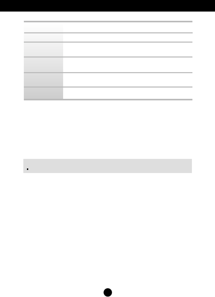
Specifications W1971SC
NOTE
Information in this document is subject to change without notice.
Attached ( ), Detached ( O )
Wall-outlet type or PC-outlet type
Standard USB 2.0, Bus-Power
Data Rate Max 480 Mbps
Input Sensitivity 0.7Vrms
Video Resolution Max 640 x 480 (VGA)
View Angle(Diagonal) 60˚
Analog One Channel
Stand Base
Power cord
USB
Audio
Webcam
MIC
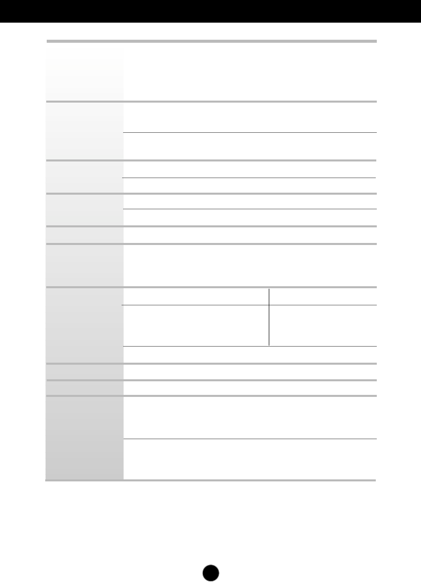
Specifications W2271SC
27
Display
Sync Input
Video Input
Resolution
Plug&Play
Power
Consumption
Dimensions
&Weight
Range
Power Input
Environmental
Conditions
22 inches (55.867 cm) Flat Panel Active matrix-TFT LCD
Anti-Glare coating
Visible diagonal size : 55.867 cm
0.282 mm pixel pitch
Horizontal Freq. 28 - 83 kHz (Automatic)
Vertical Freq. 56 - 75 Hz (Automatic)
Input Form Separate Sync.
SOG (Sync On Green)
Signal Input 15 pin D-Sub Connector
Input Form RGB Analog (0.7 Vp-p/ 75 ohm)
Max VESA 1680 x 1050 @60 Hz
Recommend VESA 1680 x 1050 @60 Hz
DDC 2B
On Mod :
42W(Typ.)
Sleep Mode ≤1 W
Off Mode ≤1 W
With Stand Without Stand
Width
51.96 cm / 20.46 inches 51.96 cm / 20.46 inches
Height
42.81 cm / 16.86 inches 36.41 cm / 14.34 inches
Depth
22.07 cm / 8.69 inches 5.59 cm / 2.20 inches
Weight(excl. packing) 4.5 kg (9.92 lbs)
Tilt -5˚~22˚
AC 100-240V~ 50/60Hz 1.0A
Operating Conditions
Temperature 10˚C to 35 ˚C
Humidity 10 % to 80 % non-Condensing
Storage Conditions
Temperature -20˚C to 60 ˚C
Humidity 5 % to 90 % non-Condensing
28
Specifications W2271SC
NOTE
Information in this document is subject to change without notice.
Attached ( ), Detached ( O )
Wall-outlet type or PC-outlet type
Standard USB 2.0, Bus-Power
Data Rate Max 480 Mbps
RMS Audio Output 1W+1W(R+L)
Input Sensitivity 0.7Vrms
Video Resolution Max 1600 x 1200 (2M)
View Angle(Diagonal) 65˚
Digital Two Channel
Stand Base
Power cord
USB
Audio
Webcam
MIC
29
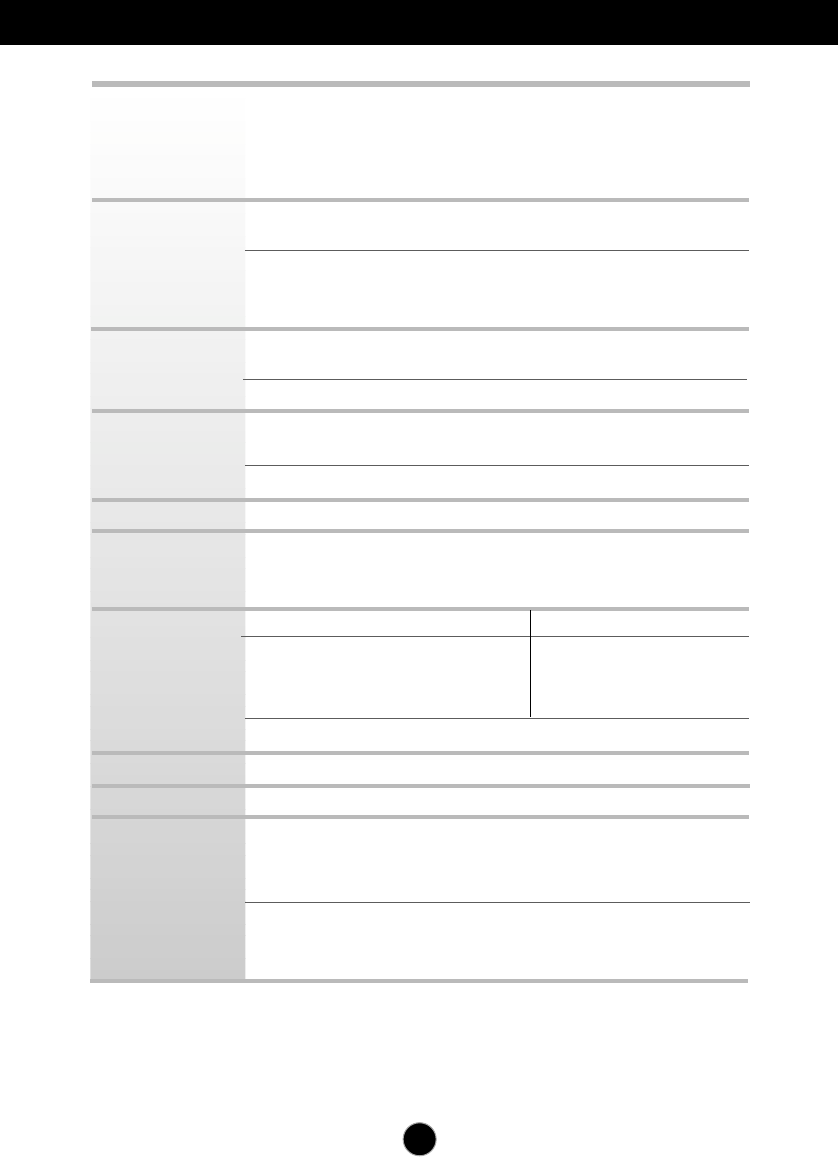
Specifications W2271TC
Display
Sync Input
Video Input
Resolution
Plug&Play
Power
Consumption
Dimensions
&Weight
Range
Power Input
Environmental
Conditions
22 inches (55.867 cm) Flat Panel Active matrix-TFT LCD
Anti-Glare coating
Visible diagonal size : 55.867 cm
0.282 mm pixel pitch
Horizontal Freq. 28 - 83 kHz (Automatic)
Vertical Freq. 56 - 75 Hz (Automatic)
Input Form Separate Sync.
SOG (Sync On Green)
Digital
Signal Input 15 pin D-Sub Connector
DVI-D Connector (Digital)
Input Form RGB Analog (0.7 Vp-p/ 75 ohm), Digital
Max Analog : VESA 1680 x 1050 @60 Hz
Digital : VESA 1680 x 1050 @60 Hz
Recommend VESA 1680 x 1050 @60 Hz
DDC 2B
On Mode :
42W(Typ.)
Sleep Mode ≤1 W
Off Mode ≤1 W
With Stand Without Stand
Width
51.96 cm / 20.46 inches 51.96 cm / 20.46 inches
Height
42.81 cm / 16.86 inches 36.41 cm / 14.34 inches
Depth
22.07 cm / 8.69 inches 5.59 cm / 2.20 inches
Weight(excl. packing) 4.5 kg (9.92 lbs)
Tilt -5˚~22˚
AC 100-240V~ 50/60Hz 1.0A
Operating Conditions
Temperature 10˚C to 35 ˚C
Humidity 10 % to 80 % non-Condensing
Storage Conditions
Temperature -20˚C to 60 ˚C
Humidity 5 % to 90 % non-Condensing
30
Specifications W2271TC
NOTE
Information in this document is subject to change without notice.
Attached ( ), Detached ( O )
Wall-outlet type or PC-outlet type
Standard USB 2.0, Bus-Power
Data Rate Max 480 Mbps
RMS Audio Output 1W+1W(R+L)
Input Sensitivity 0.7Vrms
Video Resolution Max 1600 x 1200 (2M)
View Angle(Diagonal) 65˚
Digital Two Channel
Stand Base
Power cord
USB
Audio
Webcam
MIC
31
Specifications
Preset Modes (Resolution)
*Recommend Mode
Display Modes (Resolution) Horizontal Freq. (kHz) Vertical Freq. (Hz)
1
2
3
4
5
6
7
8
9
10
11
12
13
14
*15
16
640 x 350
720 x 400
640 x 480
640 x 480
800 x 600
800 x 600
832 x 624
1024 x 768
1024 x 768
1152 x 870
1152 x 900
1280 x 1024
1280 x 1024
1440 x 900
1440 x 900
1440 x 900
31.469
31.468
31.469
37.500
37.879
46.875
49.725
48.363
60.123
68.681
61.805
63.981
79.976
55.500
55.935
70.635
70
70
60
75
60
75
75
60
75
75
65
60
75
60
60
75
Indicator
On Mode
Sleep Mode
Off Mode
Blue
Amber
Off
LED Color
MODE
VGA
VGA
VGA
VESA
VESA
VESA
MAC
VESA
VESA
MAC
VESA
VESA
VESA
VESA
VESA
VESA
W1971SC
W2271SC/W2271TC
Display Modes (Resolution) Horizontal Freq. (kHz) Vertical Freq. (Hz)
1
2
3
4
5
6
7
8
9
10
11
*12
720 x 400
640 x 480
640 x 480
800 x 600
800 x 600
1024 x 768
1024 x 768
1152 x 864
1280 x 1024
1280 x 1024
1680 x 1050
1680 x 1050
31.468
31.469
37.500
37.879
46.875
48.363
60.123
67.500
63.981
79.976
64.674
65.290
70
60
75
60
75
60
75
75
60
75
60
60
VGA
VGA
VGA
VESA
VESA
VESA
VESA
VESA
VESA
VESA
VESA
VESA
32
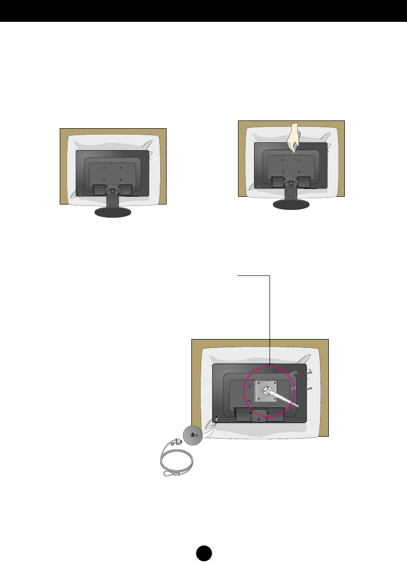
Installing the Wall mount plate
This monitor satisfies the specifications of the Wall mount plate or
the interchange device.
1.
After moving the product to face
downward, make sure to place it on a
soft cloth or a cushion to avoid
surface damage.
2. Separate the stand using a
screwdriver as shown in the picture.
3.
Install the Wall mount plate.
Wall mount plate(Separate purchase)
This is stand-type or wall mount type and is
connectable with Wall mount plate.
Please refer to the installation guide for
more details, which is provided when Wall
mount plate is purchased.
Kensington Security Slot
Connected to a locking cable that
can be purchased separately at
most computer stores.

Digitally yours
Regulatory Information cont.
FCC Compliance Statement
This equipment has been tested and found to comply
within the limits of a Class B digital device pursuant to Part
15 of the FCC Rules. These limits are designed to provide
reasonable protection against harmful interference in a
residential installation.
This equipment generates, uses, and can radiate radio
frequency energy and if not installed and used in
accordance with the instructions, may cause harmful
interference to radio communications. However, there is
no guarantee that interference will not occur in a particular
installation.
If this equipment does cause harmful interference to radio
or television reception (which can be determined by
turning the equipment on and off), the user is encouraged
to try to correct the interference by using one or more of
the following measures:
Reorient or relocate the receiving antenna.
Increase the separation between the equipment and
the receiver.
Connect the equipment into an outlet on a circuit
different from that to which the receiver is connected.
Consult the dealer or an experienced radio/TV
technician for help.
Caution: Changes or modifications not expressly approved
by the party responsible for compliance could void the
user's (or your) authority to operate the equipment. Only
peripherals (digital input/output devices, terminals, printers,
etc.) certified to comply with the Class B limits may be
attached to this monitor. Operation with non-certified
peripherals is likely to result in interference to radio and TV
reception. Only shielded signal cables may be used with
this System.
Canadian DOC Notice
This Class B digital apparatus meets all requirements of
the Canadian Interference-Causing Equipment
Regulations. Cet appareil numérique de la classe B
respecte toutes les exigences du Règlement sur le
matériel brouilleur du Canada.
CE Conformity Notice
(for Europe)
Products with the “CE” Marking comply with the EMC
Directive(89/336/EEC) and LOW VOLTAGE Directive
(73/23/EEC) issued by the Commission of the European
Community.
Compiance with these directives implies conformity to the
following European Norms :
• EN 55022 ; Radio Frequency Interference
• EN 55024 ; Electromagnetic Immunity
• EN 61000-3-2 ; Power Line Harmonics
• EN 61000-3-3 ; Voltage Fluctuations
• EN 60950-1 ; Product Safety
Low Radiation Compliance (MPR II)
This monitor meets one of the strictest guidelines available
today for low radiation emissions, offering the user extra
shielding and an antistatic screen coating. These
guidelines, set forth by a government agency in Sweden,
limit the amount of emission allowed in the Extremely Low
Frequency (ELF) and Very Low Frequency (VLF)
electromagnetic range.
01
NOTICE
The regulations are applied only to the products with the
ID LABEL indicating specific requirements.
NOTICE
The regulations are applied only to the products with the
ID LABEL indicating specific requirements.
NOTICE
The regulations are applied only to the products with the
ID LABEL indicating specific requirements.
TCO'99 (TCO'99 applied model only)
Congratulations!
You have just purchased a TCO’99 approved and labelled
product! Your choice has provided you with a product
developed for professional use. Your purchase has also
contributed to reducing the burden on the environment and
also to the further development of environmentally
adapted electronics products.
Regulatory Information cont.
02
Why do we have environmentally labelled computers?
In many countries, environmental labelling has become an
established method for encouraging the adaptation of
goods and services to the environment. With the growing
manufacture and usage of electronic equipment
throughout the world, there is a recognized concern for the
materials and substances used by electronic products
with regards to their eventual recycling and disposal. By
proper selection of these materials and substances, the
impact on the environment can be minimized.
There are also other characteristics of a computer, such as
energy consumption levels, that are important from the
viewpoints of both the work (internal) and natural (external)
environments. Electronic equipment in offices is often left
running continuously, resulting in unnecessary
consumption of large amounts of energy and additional
power generation. From the standpoint of carbon dioxide
emissions alone, it is vital to save energy.
What does labelling involve?
The product meets the requirements for the TCO’99
scheme which provides for international and environmental
labelling of personal computers and/or displays.
The labelling scheme was developed as a joint effort by the
TCO (The Swedish Confederation of Professional
Employees), Svenska Naturskyddsforeningen
(The Swedish Society for Nature Conservation) and
Statens Energimyndighet (The Swedish National
Energy Administration).
Approval requirements cover a wide range of issues:
ecology, ergonomics, emission of electrical and magnetical
fields, energy consumption and electrical safety.
Ecological criteria impose restrictions on the presence and
use of heavy metals, brominated and chlorinated flame
retardants, and other substances. The product must be
prepared for recycling and the manufacturing site(s) shall
be certified according to ISO14001 or EMAS registered.
Energy requirements include a demand that the system
unit and/or display, after a certain period of inactivity,
shall reduce its power consumption to a lower level in one
or more stages. The length of time to reactivate the system
unit shall be reasonable for the user.
Labelled products must meet strict environmental
demands, for example, in respect of the reduction of
electrical and magnetical fields as well as work load and
visual ergonomics.
Below you will find a brief summary of the ecological
requirements met by this product. The complete
ecological criteria document can be found at TCO
Development’s website http://www.tcodevelopment.com
or may be ordered from:
TCO Development
SE-114 94 STOCKHOLM, Sweden
Fax: +46 8 782 92 07
Email : development@tco.se
Information regarding TCO’99 approved and labelled
products may also be obtained at
http://www.tcodevelopment.com
Ecological requirements
Flame retardants
Flame retardants may be present in printed wiring board
laminates, cables, and housings. Their purpose is to
prevent, or at least to delay the spread of fire. Up to 30%
by weight of the plastic in a computer casing can consist of
flame retardant substances. Many flame retardants
contain bromine or chlorine, and these flame retardants
are chemically related to PCBs (polychlorinated
biphenyls). Both the flame retardants containing bromine
or chlorine and the PCBs are suspected of giving rise to
health effects, including reproductive damage in fish-
eating birds and mammals, due to the bio-accumulative*
processes when not disposed of in accordance with strict
standards for disposal.
TCO’99 requires that plastic components weighing more
than 25 grams shall not contain flame retardants with
organically bound bromine or chlorine. Flame retardants
are allowed in the printed wiring board laminates due to
the lack of commercially available alternatives.
Cadmium**
Cadmium is present in rechargeable batteries and in the
colour-generating layers of certain computer displays.
TCO’99 requires that batteries, the colour-generating
layers of display screens, and the electrical or electronics
components shall not contain any cadmium.
Mercury**
Mercury is sometimes found in batteries, relays and
switches. TCO’99 requires that batteries shall not contain
any mercury. It also demands that mercury is not present
in any of the electrical or electronics components
associated with the labelled unit. There is however one
Regulatory Information cont.
03
exception. Mercury is, for the time being, permitted in the
back light system of flat panel monitors as there today is
no commercially available alternative. TCO aims on
removing this exception when a mercury free alternative is
available.
Lead**
Lead can be found in picture tubes, display screens,
solders and capacitors. TCO’99 permits the use of lead
due to the lack of commercially available alternatives, but
in future requirements TCO Development aims at
restricting the use of lead.
_____________________________________________
* Bio-accumulative is defined as substances which
accumulate in living organisms.
**Lead, Cadmium and Mercury are heavy metals
which are bio-accumulative.
TCO’03
(TCO’03 applied model only)
Congratulations!
The display you have just purchased carries the TCO’03
Displays label.
This means that your display is designed,manufactured
and tested according to some of the strictest quality and
environmental requirements in the world. This makes for a
high performance product, designed with the user in focus
that also minimizes the impact on our natural environment.
Some of the features of the TCO’03 Display requirements:
Ergonomics
• Good visual ergonomics and image quality in order to
improve the working environment for the user and to
reduce sight and strain problems. Important
parameters are luminance, contrast, resolution,
reflectance, colour rendition and image stability.
Energy
• Energy-saving mode after a certain time – beneficial
both for the user and the environment
• Electrical safety
Emissions
• Electromagnetic fields
• Noise emissions
Ecology
• The product must be prepared for recycling and the
manufacturer must have a certified environmental
management system such as EMAS or ISO 14 001
• Restrictions on
chlorinated and brominated flame retardants and
polymers
heavy metals such as cadmium, mercury and lead.
The requirements included in this label have been
developed by TCO Development in co-operation with
scientists, experts, users as well as manufacturers all over
the world. Since the end of the 1980s TCO has been
involved in influencing the development of IT equipment in
a more user-friendly direction. Our labelling system started
with displays in 1992 and is now requested by users and
IT-manufacturers all over the world.
For more information, please visit
www.tcodevelopment.com
Information for Environmental Preservation
LGE. announced the 'LG Declaration for a Cleaner
Environment' in 1994, and this ideal has served as a
guiding managerial principle ever since. The Declaration is
a foundation that has allowed us to undertake
environmentally friendly activities in careful consideration
of economic, environmental, and social aspects.
We promote activities for environmental preservation, and
we specifically develop our products to embrace the
concept of environment-friendly.
We minimize the hazardous materials contained in our
products. For example, there is no cadmium to be found in
our monitors.
Information for recycling
This monitor may contain parts which could be hazardous
to the environment. It is important that this monitor be
recycled after use.
LGE. handles all waste monitors through an
environmentally acceptable recycling method. There are
several take-back and recycling systems currently in
English
Regulatory Information cont.
04
operation worldwide. Many parts will be reused and
recycled, while harmful substances and heavy metals are
treated by an environmentally friendly method.
If you want to find out more information about our
recycling program, please contact your local LG vendor or
a corporate representative of LG.
We set our vision and policies on a cleaner world by
selecting the issue of the global environment as a task for
corporate improvement. Please visit our website for more
information about our ‘green’ policies.
http://www.lge.com/about/environment/html/Recycling.jsp
Informationen zur Erhaltung der Umwelt
Im Jahr 1994 verkündete LGE die 'LG Declaration for a
Cleaner Environment' (LG Erklärung für eine sauberere
Umwelt). Seitdem dient dieses Ideal als führendes Prinzip
des Unternehmens. Diese Erklärung war die Basis für die
Durchführung von
umweltfreundlichen Aktivitäten, wobei wirtschaftliche,
umweltbezogene und soziale Aspekte in die
Überlegungen mit einbezogen wurden.
Wir fördern Aktivitäten zum Schutz der Umwelt und die
Entwicklung unserer Produkte ist darauf ausgerichtet,
unserem Konzept bezüglich Umweltfreundlichkeit gerecht
zu werden.
Wir sind darauf bedacht, den Anteil der in unseren
Produkten enthaltenen schädlichen Materialien zu
minimieren. So ist in unseren Monitoren beispielsweise
kein Kadmium zu finden.
Informationen zum Thema Recycling
Dieser Monitor enthält Teile, die umweltschädlich sein
können. Es ist unbedingt erforderlich, dass der Monitor
recycelt wird, nachdem er außer Dienst gestellt wurde.
Bei LGE. werden alle ausrangierten Monitore in einem
unter umweltbezogenen Aspekten geeigneten Verfahren
recycelt. Augenblicklich sind weltweit mehrere
Rücknahme- und Recyclingsysteme im Einsatz. Viele
Teile werden wieder verwendet und recycelt. Schädliche
Substanzen und Schwermetalle werden durch
umweltverträgliche Verfahren behandelt.
Falls Sie mehr über unser Recyclingprogramm erfahren
möchten, wenden Sie sich bitte an Ihren lokalen LG-
Händler oder einen Unternehmensvertreter von LG.
Wir richten unsere Firmenpolitik auf eine sauberere
Umwelt hin aus, indem wir umweltspezifische Aspekte als
wichtigen Punkt in die Weiterentwicklung unseres
Unternehmens einfließen lassen. Zusätzliche
Informationen über unsere ‘grüne’ Firmenpolitik erhalten
Sie auf unserer Website.
http://www.lge.com/about/environment/html/Recycling.jsp
Information sur la protection del’environnement
LGE. a publié sa 'Déclaration en faveur d’un
environnement plus propre' en 1994 et celle-ci est restée,
depuis lors, un principe directeur de notre entreprise.
Cette déclaration a servi de base à notre réflexion et nous
a permis de prendre en compte à la fois les aspects
économiques et sociaux de nos activités, tout en
respectant l’environnement.
Nous encourageons les activités en faveur de la
préservation de l’environnement et c’est dans cet esprit
que nous développons nos produits : nous réduisons au
minimum les matières dangereuses qui entrent dans leur
composition et l’on ne trouve pas de cadmium, par
exemple, dans nos moniteurs.
Information sur le recyclage
Ce moniteur peut contenir des composants qui présentent
un risque pour l’environnement. Il est donc important que
celui-ci soit recyclé après usage.
LGE. traite les moniteurs en fin de cycle conformément à
une méthode de recyclage respectueuse de
l’environnement. Nous reprenons nos produits et les
recyclons dans plusieurs sites répartis dans le monde
entier. De nombreux composants sont réutilisés et
recyclés, et les matières dangereuses, ainsi que les
métaux lourds, sont traités selon un procédé écologique.
Si vous souhaitez plus de renseignements sur notre
programme de recyclage, veuillez contacter votre
revendeur LG ou un l’un de nos représentants.
Nous voulons agir pour un monde plus propre et croyons
au rôle de notre entreprise dans l’amélioration de
l’environnement. Pour plus de renseignements sur notre
politique “verte”, rendez visite à notre site :
http://www.lge.com/about/environment/html/Recycling.jsp
Deutsch
Français
05
Regulatory Information cont.
Informazioni per la tutela dell’ambiente
La LGE. ha annunciato nel 1994 la cosiddetta 'LG
Declaration for a Cleaner Environment' (Dichiarazione di
LG a favore di un ambiente più pulito), un ideale che da
allora funge da principio ispiratore della gestione
aziendale. La dichiarazione rappresenta il fondamento che
consente di intraprendere attività a favore dell'ambiente
tenendo conto degli aspetti economici, ambientali e
sociali.Noi della LG, promuoviamo attività a favore della
tutela dell'ambiente sviluppando appositamente i nostri
prodotti per cogliere il concetto del rispetto dell’ambiente
riducendo i materiali dannosi presenti nei nostri prodotti.
Ad esempio nei nostri monitor non è presente il cadmio.
Informazioni per il riciclaggio
Il monitor può presentare componenti che potrebbero
risultare eventualmente dannosi per l'ambiente. È
importante che il monitor sia riciclato al termine del suo
utilizzo.
La LGE. gestisce tutti i monitor di rifiuto con un metodo di
riciclaggio soddisfacente dal punto di vista ambientale. In
tutto il mondo sono attualmente in funzione numerosi
sistemi di riciclaggio e recupero. I diversi componenti sono
riutilizzati e riciclati, mentre le sostanze dannose e i metalli
pesanti vengono trattati con un metodo rispettoso
dell’ambiente.
Se si desiderano maggiori informazioni in merito al
programma di riciclaggio, è consigliabile rivolgersi al
proprio rivenditore LG o ad un rappresentante aziendale
della LG.
Noi della LG impostiamo la nostra visione e le nostre
politiche a favore di un mondo più pulito ponendo la
questione dell'ambiente dal punto di vista globale come
una mansione rivolta al miglioramento della nostra
azienda. Vi invitiamo a visitare il nostro sito internet per
ulteriori informazioni sulla nostra politica “verde”.
http://www.lge.com/about/environment/html/Recycling.jsp
Información para la conservación
medioambiental
LGE. presentó la 'Declaración para un entorno más limpio
de LG' en 1994 y este ideal ha servido para guiar nuestros
principios empresariales desde entonces. La Declaración
es la base que nos ha permitido llevar a cabo tareas que
respetan el medio ambiente siempre teniendo en cuenta
aspectos sociales,
económicos y medioambientales.
Promocionamos actividades orientadas a la conservación
del medio ambiente y desarrollamos nuestros productos
específicamente para que se ajusten a la filosofía que
protege el entorno.
Reducimos al máximo el uso de materiales de riesgo en
nuestros productos. Un ejemplo de ello es la ausencia
total de cadmio en nuestros monitores.
Información para el reciclaje
Este monitor puede contener piezas que entrañen riesgos
medioambientales. Es importante reciclar este monitor
después de su utilización.
LGE. trata todos los monitores usados siguiendo un
método de reciclaje que no daña al entorno. Contamos
con diversos sistemas de recuperación y reciclaje que
funcionan a nivel mundial en la actualidad. Es posible
reciclar y reutilizar muchas de las piezas, mientras que las
sustancias dañinas y los metales pesados se tratan
siguiendo un método que no perjudique al medio
ambiente. Si desea obtener más información acerca del
programa de reciclaje, póngase en contacto con su
proveedor local de LG o con un representante empresarial
de nuestra marca.
Basamos nuestra visión y nuestras políticas en un mundo
más limpio y para ellos optamos por un entorno global
como tarea principal de nuestra evolución como empresa.
Visite nuestra página Web para obtener más información
sobre nuestras políticas ecológicas.
http://www.lge.com/about/environment/html/Recycling.jsp
Informações relacionadas à preservação
ambiental
A LGE. anunciou a 'LG Declaration for a Cleaner
Environment' (Declaração da LG para um ambiente mais
limpo) em 1994 e esse ideal tem servido desde então
como um princípio administrativo de orientação. A
Declaração é a base que nos tem permitido realizar
atividades favoráveis ao ambiente com consideração
atenta aos aspectos econômicos, ambientais e sociais.
Promovemos atividades de preservação ambiental e
desenvolvemos nossos produtos para englobar
Italiano
Espanõl
Português
06
Regulatory Information cont.
especificamente o conceito de favorável ao ambiente.
Reduzimos os materiais perigosos contidos em nossos
produtos. Por exemplo, não há cádmio em nossos
monitores.
Informações relacionadas à reciclagem
Este monitor pode conter peças que podem representar
riscos ao ambiente. É importante que ele seja reciclado
após o uso.
A LGE. cuida de todos os monitores descartados através
de um método de reciclagem agradável ao ambiente. Há
vários sistemas de devolução e reciclagem atualmente
em operação no mundo. Muitas peças serão reutilizadas
e recicladas e as substâncias nocivas e os metais
pesados passarão por tratamento através de um método
favorável ao ambiente.
Para obter mais informações sobre nosso programa de
reciclagem, entre em contato com seu fornecedor LG
local ou com um representante corporativo da LG.
Definimos nossa visão e nossas políticas relacionadas a
um mundo mais limpo selecionando a questão do
ambiente global como uma tarefa de aprimoramento
corporativo. Visite nosso site para obter mais informações
sobre nossas políticas de meio ambiente.
http://www.lge.com/about/environment/html/Recycling.jsp
Informatie met betrekking tot het behoud van
het milieu
LGE. publiceerde in 1994 de 'LG Declaration for a Cleaner
Environment' (de LG-verklaring met betrekking tot een
schoner milieu). Deze verklaring en het ideaal van een
schoner milieu fungeren sindsdien als een bestuurlijke
leidraad voor onze onderneming. Op basis van deze
verklaring ontplooien wij milieuvriendelijke activiteiten,
waarbij er zowel met sociale en economische aspecten,
als met milieuaspecten zorgvuldig rekening wordt
gehouden.
Wij ondersteunen activiteiten die zijn gericht op het
behoud van het milieu en wij houden bij het ontwikkelen
onze producten specifiek rekening met de
milieuvriendelijkheid van onze producten.
Wij minimaliseren het gebruik van schadelijke stoffen in
onze producten. Er wordt bijvoorbeeld geen cadmium
verwerkt in onze monitors.
Nederlands
Informatie met betrekking tot recycling
Deze monitor bevat materialen die schadelijk zouden
kunnen zijn voor het milieu. Het is belangrijk dat deze
monitor aan het einde van zijn levensduur wordt
gerecycled.
LGE. verwerkt alle afvalmonitors via een milieuvriendelijke
recyclingmethode. Hiervoor worden er momenteel
wereldwijd verscheidene inname- en recyclingsystemen
gehanteerd. Een groot aantal onderdelen wordt opnieuw
gebruikt en gerecycled, waarbij schadelijke stoffen en
zware metalen volgens een milieuvriendelijke methode
worden verwerkt.
Voor meer informatie over ons recyclingprogramma kunt u
contact opnemen met uw plaatselijke LG-
vertegenwoordiger of een LG-vestiging.
Onze visie en ons beleid met betrekking tot een schonere
wereld vloeien voort uit het feit dat wij het milieu hebben
aangemerkt als een onderwerp dat speciale aandacht
verdient binnen onze onderneming. Bezoek onze website
voor meer informatie over ons 'groene' beleid.
http://www.lge.com/about/environment/html/Recycling.jsp
»ÌÙÓχˆËˇ ÔÓ Óı‡Ì ÓÍÛʇ˛˘ÂÈ Ò‰˚
¬ 1994 „Ó‰Û ÍÓÔÓ‡ˆËˇ LGE ÓÔÛ·ÎËÍÓ‚‡Î‡
'ƒÂÍ·‡ˆË˛ LG ÔÓ Óı‡Ì ÓÍÛʇ˛˘ÂÈ Ò‰˚',
ÍÓÚÓ‡ˇ Ò ÚÂı ÔÓ ÒÎÛÊËÚ ÓÒÌÓ‚Ì˚Ï ÔË̈ËÔÓÏ
ÛÔ‡‚ÎÂÌˡ. Õ‡ ÓÒÌÓ‚Â ˝ÚÓÈ ‰ÂÍ·‡ˆËË Ï˚ ÒÏÓ„ÎË
Ô‰ÔËÌˇÚ¸ ‰ÂÈÒڂˡ, Ó·ÂÒÔ˜˂‡˛˘ËÂ
·ÂÁÓÔ‡ÒÌÓÒÚ¸ ÓÍÛʇ˛˘ÂÈ Ò‰˚, Û‰ÂΡˇ ÔË ˝ÚÓÏ
‰ÓÎÊÌÓ ‚ÌËχÌË ˝ÍÓÌÓÏ˘ÂÒÍËÏ, ˝ÍÓÎӄ˘ÂÒÍËÏ Ë
ÒӈˇθÌ˚Ï ‡ÒÔÂÍÚ‡Ï.
Ã˚ ÒÚËÏÛÎËÛÂÏ ‰ÂˇÚÂθÌÓÒÚ¸ ÔÓ Óı‡ÌÂ
ÓÍÛʇ˛˘ÂÈ Ò‰˚, Û‰ÂΡˇ ÓÒÓ·Ó ‚ÌËχÌËÂ
‡Á‡·ÓÚÍ ̇¯ÂÈ ÔÓ‰Û͈ËË ‚ ÒÓÓÚ‚ÂÚÒÚ‚ËË Ò
ÍÓ̈ÂÔˆËÂÈ ˝ÍÓÎӄ˘ÂÒÍÓÈ ·ÂÁÓÔ‡ÒÌÓÒÚË.
Ã˚ Ò‚Ó‰ËÏ Í ÏËÌËÏÛÏÛ ÒÓ‰ÂʇÌË ÓÔ‡ÒÌ˚ı
‚¢ÂÒÚ‚ ‚ ̇¯ÂÈ ÔÓ‰Û͈ËË. Õ‡ÔËÏÂ, ‚ ̇¯Ëı
ÏÓÌËÚÓ‡ı ‚˚ Ì ̇ȉÂÚ ͇‰Ïˡ.
»ÌÙÓχˆËˇ ÔÓ ÛÚËÎËÁ‡ˆËË ÓÚıÓ‰Ó‚
›ÚÓÚ ÏÓÌËÚÓ ÏÓÊÂÚ ÒÓ‰Âʇڸ ÍÓÏÔÓÌÂÌÚ˚,
ÍÓÚÓ˚ ÏÓ„ÛÚ Ì‡ÌÂÒÚË Û˘Â· ÓÍÛʇ˛˘ÂÈ Ò‰Â.
Russian
07
Regulatory Information cont.
EPA
(EPA applied model only)
ENERGY STAR
is a set of power-saving guidelines
issued by the U.S. Environmental Protection
Agency(EPA).
NOM MARK (Mexico only)
ÕÂÓ·ıÓ‰ËÏÓ ÛÚËÎËÁËÓ‚‡Ú¸ ÏÓÌËÚÓ ÔÓÒÎÂ
ËÒÔÓθÁÓ‚‡Ìˡ.
KÓÔÓ‡ˆËˇ LGE Ô‡·‡Ú˚‚‡ÂÚ ‚Ò ·‡ÍÓ‚‡ÌÌ˚Â
ÏÓÌËÚÓ˚ Ò ÔÓÏÓ˘¸˛ ˝ÍÓÎӄ˘ÂÒÍË ÔËÂÏÎÂÏÓ„Ó
ÏÂÚÓ‰‡ ÛÚËÎËÁ‡ˆËË ÓÚıÓ‰Ó‚. œÓ ‚ÒÂÏÛ ÏËÛ
‰ÂÈÒÚ‚Û˛Ú ÒËÒÚÂÏ˚ ÛÚËÎËÁ‡ˆËË ÓÚıÓ‰Ó‚ Ë ‚ÓÁ‚‡Ú‡
ËÒÔÓθÁÓ‚‡ÌÌÓÈ ÔÓ‰Û͈ËË. ÃÌÓ„Ë ÍÓÏÔÓÌÂÌÚ˚
·Û‰ÛÚ ‚ÚÓ˘ÌÓ ËÒÔÓθÁÓ‚‡Ì˚ Ë ÛÚËÎËÁËÓ‚‡Ì˚, ‚ ÚÓ
‚ÂÏˇ Í‡Í ‚‰Ì˚ ‚¢ÂÒÚ‚‡ Ë ÚˇÊÂÎ˚ ÏÂÚ‡ÎÎ˚
·Û‰ÛÚ Ó·‡·ÓÚ‡Ì˚ Ò ÔÓÏÓ˘¸˛ ˝ÍÓÎӄ˘ÂÒÍË
ÔËÂÏÎÂÏÓ„Ó ÏÂÚÓ‰‡.
«‡ ·ÓΠÔÓ‰Ó·ÌÓÈ ËÌÙÓχˆËÂÈ ÔÓ Ì‡¯ÂÈ
ÔÓ„‡ÏÏ ÛÚËÎËÁ‡ˆËË ÓÚıÓ‰Ó‚ Ó·‡˘‡ÈÚÂÒ¸ Í
ÏÂÒÚÌÓÏÛ ÔÓÒÚ‡‚˘ËÍÛ ËÎË Ô‰ÒÚ‡‚ËÚÂβ
ÍÓÔÓ‡ˆËË LG.
Ã˚ ÓËÂÌÚËÛÂÏÒˇ ̇ Ó·ÂÒÔ˜ÂÌË ˝ÍÓÎӄ˘ÂÒÍÓÈ
·ÂÁÓÔ‡ÒÌÓÒÚË, ÒÚ‡‚ˇ Ò· ˆÂθ˛ „ÎÓ·‡Î¸ÌÛ˛ Á‡˘ËÚÛ
ÓÍÛʇ˛˘ÂÈ Ò‰˚. ƒÓÔÓÎÌËÚÂθÌÛ˛ ËÌÙÓχˆË˛
Ó Ì‡¯ÂÈ ÔÓÎËÚËÍ ÔÓ Óı‡Ì ÓÍÛʇ˛˘ÂÈ Ò‰˚ ‚˚
ÏÓÊÂÚ ̇ÈÚË Ì‡ ̇¯ÂÏ Ò‡ÈÚÂ:
http://www.lge.com/about/environment/html/Recycling.jsp
As an ENERGY STAR Partner LGE U. S.
A.,Inc. has determined that this product
meets the ENERGY STAR guidelines for
energy efficiency.
08
Regulatory Information cont.
1.When this crossed-out wheeled bin symbol is attached
to a product it means the product is covered by the
European Directive 2002/96/EC.
2.All electrical and electronic products should be
disposed of separately from the municipal waste
stream via designated collection facilities appointed by
the government or the local authorities.
3.The correct disposal of your old appliance will help
prevent potential negative consequences for the
environment and human health.
4.For more detailed information about disposal of your
old appliance, please contact your city office, waste
disposal service or the shop where you purchased the
product.
Disposal of your old appliance
1.Quando su un prodotto è riportato il simbolo di
1.När den här symbolen med en överkryssad
soptunna på hjul sitter på en produkt innebär det
att den regleras av European Directive
2002/96/EC.
2.Alla elektriska och elektroniska produkter bör
kasseras via andra vägar än de som finns för
hushållsavfall, helst via för ändamålet avsedda
uppsamlingsanläggningar som myndigheterna
utser.
3.Om du kasserar din gamla apparat på rätt sätt
så bidrar du till att förhindra negativa
konsekvenser för miljön och människors hälsa.
4.Mer detaljerad information om kassering av din
gamla apparat kan får av kommunen,
renhållningsverket eller den butik där du köpte
produkten.
1.Als het symbool met de doorgekruiste verrijdbare
afvalbak op een product staat, betekent dit dat
het product valt onder de Europese Richtlijn
2002/96/EC.
2.Elektrische en elektronische producten mogen
niet worden meegegeven met het huishoudelijk
afval, maar moeten worden ingeleverd bij
speciale inzamelingspunten die door de lokale of
landelijke overheid zijn aangewezen.
3.De correcte verwijdering van uw oude toestel
helpt negatieve gevolgen voor het milieu en de
menselijke gezondheid voorkomen.
Smaltimento delle apparecchiature obsolete
Kassering av din gamla apparat
Uw oude toestel wegdoen
1.Ce symbole, représentant une poubelle sur
roulettes barrée d'une croix, signifie que le
produit est couvert par la directive européenne
2002/96/EC.
2.Les éléments électriques et électroniques
doivent être jetés séparément, dans les vide-
ordures prévus à cet effet par votre municipalité.
3.Une élimination conforme aux instructions aidera
à réduire les conséquences négatives et risques
éventuels pour l'environnement et la santé
humaine.
4.Pour plus d'information concernant l'élimination
de votre ancien appareil, veuillez contacter votre
mairie, le service des ordures ménagères ou
encore la magasin où vous avez acheté ce
produit.
Élimination de votre ancien appareil
un bidone della spazzatura barrato da una croce
significa che il prodotto è coperto dalla direttiva
europea 2002/96/EC.
2.Tutti i prodotti elettrici ed elettronici dovrebbero
essere smaltiti separatamente rispetto alla
raccolta differenziata municipale, mediante
impianti di raccolta specifici designati dal
governo o dalle autorità locali.
3.Il corretto smaltimento delle apparecchiature
obsolete contribuisce a prevenire possibili
conseguenze negative sulla salute umana e
sull'ambiente.
4.Per informazioni più dettagliate sullo smaltimento
delle apparecchiature obsolete, contattare il
comune, il servizio di smaltimento rifiuti o il
negozio in cui è stato acquistato il prodotto.
English
French
Italian
Swedish
Dutch
WEEE (for Europe )
Regulatory Information cont.
09
1.Wenn dieses Symbol eines durchgestrichenen
Abfalleimers auf einem Produkt angebracht ist,
unterliegt dieses Produkt der europäischen
Richtlinie 2002/96/EC.
2.Alle Elektro- und Elektronik-Altgeräte müssen
getrennt vom Hausmüll über dafür staatlich
vorgesehenen Stellen entsorgt werden.
3.Mit der ordnungsgemäßen Entsorgung des alten
Geräts vermeiden Sie Umweltschäden und eine
Gefährdung der persönlichen Gesundheit.
4.Weitere Informationen zur Entsorgung des alten
Geräts erhalten Sie bei der Stadtverwaltung,
beim Entsorgungsamt oder in dem Geschäft, wo
Sie das Produkt erworben haben.
1.ŸÙ·Ó ¤Ó· ÚÔ˚fiÓ ‰È·ı¤ÙÂÈ ÙÔ ‰‡Ì‚ÔÏÔ ÂÓfi˜
‰È·ÁÚ·Ì̤ÓÔ˘ οϷıÔ˘ ·ÔÚÚÈÌÌ¿ÙˆÓ, ÙfiÙ ÙÔ ÚÔ˚fiÓ
ηχÙÂÙ·È ·fi ÙËÓ E˘Úˆ·˚΋ O‰ËÁ›· 2002/96/EOK.
2.H ·fiÚÚÈ„Ë fiÏˆÓ ÙˆÓ ËÏÂÎÙÚÈÎÒÓ Î·È ËÏÂÎÙÚÔÓÈÎÒÓ
ÚÔ˚fiÓÙˆÓ Ú¤ÂÈ Ó· Á›ÓÂÙ·È ¯ˆÚÈÛÙ¿ ·fi Ù· ÁÂÓÈο
ÔÈÎȷο ·ÔÚÚ›ÌÌ·Ù· ̤ۈ ηıÔÚÈṲ̂ӈÓ
ÂÁηٷÛÙ¿ÛÂˆÓ Û˘ÏÏÔÁ‹˜ ·ÔÚÚÈÌÌ¿ÙˆÓ, ÔÈ Ôԛ˜
¤¯Ô˘Ó ‰ËÌÈÔ˘ÚÁËı› ›Ù ·fi ÙËÓ Î˘‚¤ÚÓËÛË ‹ ·fi ÙȘ
ÙÔÈΤ˜ ·Ú¯¤˜.
3.H ÛˆÛÙ‹ ·fiÚÚÈ„Ë Ù˘ ·ÏÈ¿˜ Û·˜ Û˘Û΢‹˜ ı·
‚ÔËı‹ÛÂÈ ÛÙËÓ ·ÔÙÚÔ‹ Èı·ÓÒÓ ·ÚÓËÙÈÎÒÓ Û˘ÓÂÈÒÓ
ˆ˜ ÚÔ˜ ÙÔ ÂÚÈ‚¿ÏÏÔÓ Î·È ÙËÓ ˘Á›· ÙÔ˘ ·ÓıÚÒÔ˘.
4.°È· ÈÔ ÏÂÙÔÌÂÚ›˜ ÏËÚÔÊÔڛ˜ Û¯ÂÙÈο Ì ÙËÓ
·fiÚÚÈ„Ë Ù˘ ·ÏÈ¿˜ Û·˜ Û˘Û΢‹˜, ÂÈÎÔÈÓˆÓ‹ÛÙ ÌÂ
ÙÔ ·ÚÌfi‰›Ô ÙÔÈÎfi ÁÚ·Ê›Ô, ˘ËÚÂÛ›· ‰È¿ıÂÛ˘ ÔÈÎÈ·ÎÒÓ
·ÔÚÚÈÌÌ¿ÙˆÓ ‹ ÙÔ Ì·Á·Í› ·fi ÙÔ ÔÔ›Ô ·ÁÔÚ¿Û·ÙÂ ÙÔ
ÚÔ˚fiÓ.
1.Tämä merkki tuotteessa tarkoittaa, että tuote
kuuluu sähkö- ja elektroniikkalaiteromusta
annetun EU-direktiivin 2002/96/EY
soveltamisalaan.
2.Kaikki elektroniset laitteet ovat ongelmajätettä,
joten ne on toimitettava paikalliseen
keräyspisteeseen.
3.Vanhan laitteen asianmukainen hävittäminen
ehkäisee mahdollisia ympäristöön ja
terveyteen kohdistuvia haittavaikutuksia.
4.Lisätietoa vanhan laitteen hävittämisestä saat
ottamalla yhteyden paikallisiin viranomaisiin,
kierrätyskeskukseen tai myymälään, josta ostit
laitteen.
1.Når der er et tegn med et kryds over en
skraldespand, betyder det, at produktet er
omfattet af EU-direktiv 2002/96/EC.
2.Alle elektriske og elektroniske produkter skal
smides ud et andet sted end gennem den
kommunale affaldsordning ved hjælp af specielle
indsamlingsfaciliteter, der er organiseret af staten
1.Si en un producto aparece el símbolo de un contenedor
de basura tachado, significa que éste se acoge a la
Directiva 2002/96/CE.
2.Todos los aparatos eléctricos o electrónicos se deben
desechar de forma distinta del servicio municipal de
recogida de basura, a través de puntos de recogida
designados por el gobierno o las autoridades locales.
3.La correcta recogida y tratamiento de los dispositivos
inservibles contribuye a evitar riesgos potenciales para el
medio ambiente y la salud pública.
4.Para obtener más información sobre cómo deshacerse de
sus aparatos eléctricos y electrónicos viejos, póngase en
contacto con su ayuntamiento, el servicio de recogida de
basuras o el establecimiento donde adquirió el producto.
Vanhojen laitteiden hävittäminen
Entsorgung von Altgeräten
Sådan smider du dit gamle apparat ud
∞fiÚÚÈ„Ë Ù˘ ·ÏÈ¿˜ Û·˜ Û˘Û΢‹˜
Cómo deshacerse de aparatos eléctricos y
electrónicos viejos
eller de lokale myndigheder.
3.Korrekt bortskaffelse af dit gamle apparat er med
til at forhindre mulige skadevirkninger på miljøet
og menneskelig sundhed.
4.Mere detaljerede oplysninger om bortskaffelse af
dit gamle apparat kan fås ved at kontakte dit
lokale kommunekontor, renovationsselskab eller
den butik, hvor du købte produktet.
Finnish
German
Danish
Greek
Spanish
4.Wilt u meer informatie over de verwijdering van
uw oude toestel? Neem dan contact op met uw
gemeente, de afvalophaaldienst of de winkel
waar u het product hebt gekocht.
Regulatory Information cont.
10
Portuguese
Slovak
Czech
Croatian
Hungarian
Polish
Regulatory Information cont.
11
Estonian
Latvian
Lithuanian