LG Electronics USA W2363VV LCD Monitor User Manual GEN
LG Electronics USA LCD Monitor GEN
Manual

Make sure to read the Important Precautions before using the product.
Keep the User's Guide(CD) in an accessible place for future reference.
See the label attached on the product and give the information to your
dealer when you ask for service.
W2363V
User’s Guide

Important Precautions
This unit has been engineered and manufactured to ensure your personal safety,
however improper use may result in potential electrical shock or fire hazards. In
order to allow the proper operation of all safeguards incorporated in this display,
observe the following basic rules for its installation, use, and servicing.
On Safety
Use only the power cord supplied with the unit. In case you use another power
cord, make sure that it is certified by the applicable national standards if not being
provided by the supplier. If the power cable is faulty in any way, please contact the
manufacturer or the nearest authorized repair service provider for a replacement.
The power supply cord is used as the main disconnection device. Ensure that the
socket-outlet is easily accessible after installation.
Operate the display only from a power source indicated in the specifications of
this manual or listed on the display. If you are not sure what type of power supply
you have in your home, consult with your dealer.
Overloaded AC outlets and extension cords are dangerous. So are frayed power
cords and broken plugs. They may result in a shock or fire hazard. Call your service
technician for replacement.
As long as this unit is connected to the AC wall outlet, it is not disconnected from
the AC power source even if the unit is turned off.
Do not Open the Display:
There are no user serviceable components inside.
There are Dangerous High Voltages inside, even when the power is OFF.
Contact your dealer if the display is not operating properly.
To Avoid Personal Injury :
Do not place the display on a sloping shelf unless properly secured.
Use only a stand recommended by the manufacturer.
Do not drop an object on or apply impact to the product. Do not throw any toys
or objects on the product screen.
It can cause injury to human, problem to product and damage the display.
To Prevent Fire or Hazards:
Always turn the display OFF if you leave the room for more than a short period
of time. Never leave the display ON when leaving the house.
Keep children from dropping or pushing objects into the display's cabinet
openings. Some internal parts carry hazardous voltages.
Do not add accessories that have not been designed for this display.
When the display is to be left unattended for an extended period of time, unplug
it from the wall outlet.
In the presence of thunder and lightning, never touch the power cord and signal
cable because it can be very dangerous. It can cause electric shock.
1

Important Precautions
NOTE
THE MANUFACTURER IS NOT RESPONSIBLE FOR ANY RADIO OR TV
INTRERFERENCE CAUSED BY UNAUTHORIZED MODIFICATIONS TO THIS
EQUIPMENT.SUCH MODIFICATIONS COULD VOID THE USER'S AUTHORITY
NOTE
This epuipment has been tested and found to comply with the limits for a class
B digital device,pursuant to part 15 of the FCC Rules.These limits are designed
to provide reasonable protection against harmful interference in a residential
installation.This equipment generates,uses and can radiate radio frequency
cause harmful interference to radio communications.However,there is no
guarantee that interference will not occur in a particular installation.If this
which can be determined by turning the equipment off and on,the user is
encouraged to try to correct the interference by one or more of the following
measures:
-Reorient or relocate the receiving antenna.
-Increase the separation between the equipment and the receiver.
-Connect the equipment into an outlet on a circuit different from that to which
the receiver is connected.
energy and,if not installed and used in accordance with the instructions,may
equipment does cause harmful interference to radio or television reception,
TO OPERATE THE EQUIPMENT.
-Consult the dealer or an experienced radio/TV technician for help.
A3

Important Precautions
On Installation
Do not allow anything to rest upon or roll over the power cord, and do not place
the display where the power cord is subject to damage.
Do not use this display near water such as near a bathtub, washbowl, kitchen
sink, laundry tub, in a wet basement, or near a swimming pool.
Displays are provided with ventilation openings in the cabinet to allow the release
of heat generated during operation. If these openings are blocked, built-up heat
can cause failures which may result in a fire hazard. Therefore, NEVER:
Block the bottom ventilation slots by placing the display on a bed, sofa, rug, etc.
Place the display in a built-in enclosure unless proper ventilation is provided.
Cover the openings with cloth or other material.
Place the display near or over a radiator or heat source.
Do not rub or strike the Active Matrix LCD with anything hard as this may scratch,
mar, or damage the Active Matrix LCD permanently.
Do not press the LCD screen with your finger for a long time as this may cause
some afterimages.
Some dot defects may appear as Red, Green or Blue spots on the screen.
However, this will have no impact or effect on the display performance.
If possible, use the recommended resolution to obtain the best image quality for
your LCD display. If used under any mode except the recommended resolution,
some scaled or processed images may appear on the screen. However, this is
characteristic of the fixed-resolution LCD panel.
Leaving a fixed image on the screen for a long time may cause damage to the
screen and cause image burn-in. Make sure to use a screen saver on the product.
Burn-in and related problems are not covered by the warranty on this product.
Do not shock or scratch the front and sides of the screen with metallic objects.
Otherwise, it may cause damage to the screen.
Make sure the panel faces forward and hold it with both hands to move. If you
drop the product, the damaged product can cause electric shock or fire. Contact
an authorized the service center for repair.
Avoid high temperatures and humidity.
2
Important Precautions
3
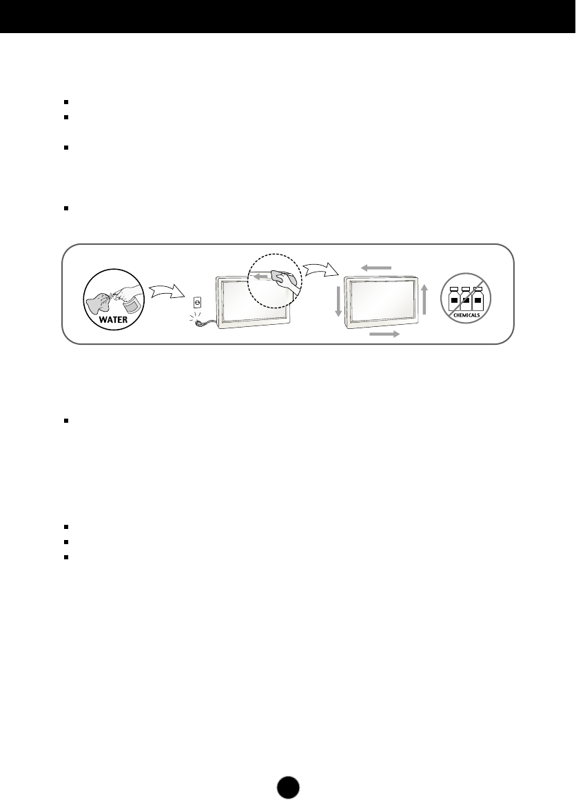
On Cleaning
Unplug the display before cleaning the face of the display screen.
Use a slightly damp (not wet) cloth. Do not use an aerosol directly on the display
screen because over-spraying may cause electrical shock.
When cleaning the product, unplug the power cord and scrub gently with a soft
cloth to prevent scratching. Do not clean with a wet cloth or spray water or
other liquids directly onto the product. An electric shock may occur. (Do not use
chemicals such as benzene, paint thinners or alcohol)
Spray water onto a soft cloth 2 to 4 times, and use it to clean the front frame;
wipe in one direction only. Too much moisture may cause staining.
On Repacking
Do not throw away the carton and packing materials. They make an ideal
container in which to transport the unit. When shipping the unit to another
location, repack it in its original material.
On Disposal (Only, Hg lamp used LCD Monitor)
The fluorescent lamp used in this product contains a small amount of mercury.
Do not dispose of this product with general household waste.
Disposal of this product must be carried out in accordance to the regulations of
your local authority.
4
Accessories
!!! Thank for selecting LGE products !!!
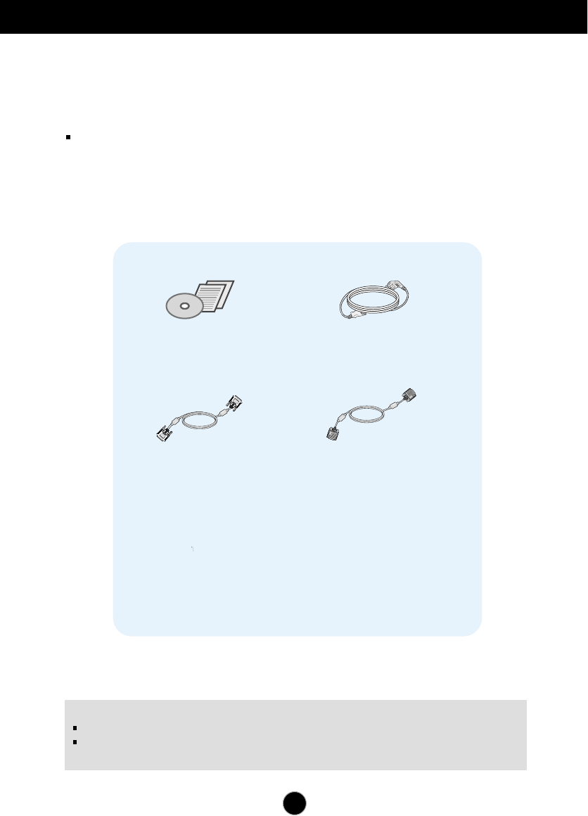
Please make sure the following items are included with your
monitor. If any items are missing, contact your dealer.
User's Guide/Cards Power Cord
(Depending on the country)
15-pin D-Sub Signal Cable
(To set it up, this signal cable may
be attached to this product before
shipping out.)
DVI-D Signal Cable
(This feature is not available
in all countries.)
IMPORTANT
This accessories may look different from those shown here.
User must use shielded signal interface cables (D-sub 15 pin cable, DVI cable) with ferrite
cores to maintain standard compliance for the product.
5
Connecting the Display
Before setting up the monitor, ensure that the power to the monitor,
the computer system, and other attached devices is turned off.
Connecting and Disassembling the stand
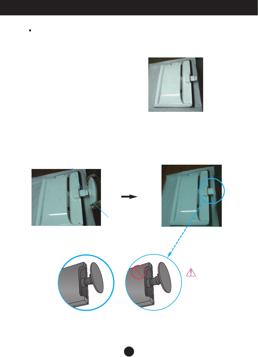
1. Place the monitor face down on the soft cloth.
2. Assemble the Stand Base into the Stand Body in the correct direction.
Make sure you push the Stand Base until the end.
Stand Base
Stand Body
The Stand Base
may fall and get
damaged or cause
injury.
Good Connection Bad Connection
6
Connecting the Display
IMPORTANT
This picture depicts the general model of connection. Your monitor may differ from the items
shown in the picture.
Do not carry the product upside down holding only the stand base. The product may fall and
get damaged or cause injury.
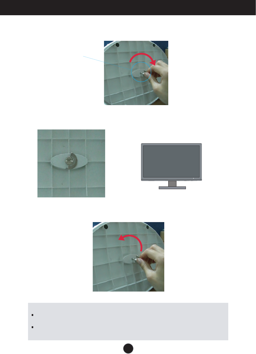
4. Then fold the screw handle flat. 5. Once assembled take the monitor up
carefully and face the front side.
6. To disconnect the Stand Base from the Stand Body, unfold the screw handle and
turn it to the left.
3. Turn the screw to the right to fix the Stand Body to the Stand Base.
Screw
Turn the screw
by using the
screw handle.
Connecting the Display
Before setting up the monitor, ensure that the power to the monitor, the computer
system, and other attached devices is turned off.
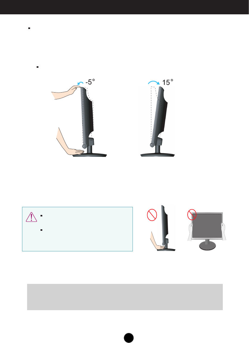
Positioning your display
1. Adjust the position of the panel in various ways for maximum comfort.
Tilt Range: -5˚~15˚
Ergonomic
It is recommended that in order to maintain an ergonomic and comfortable viewing
position, the forward tilt angle of the monitor should not exceed 5 degrees.
7
Do not touch or press the screen when
adjusting the angle of the monitor.
When adjusting the angle of the screen, do
not put your finger(s) in between the head of
the monitor and the stand body. You can
hurt your finger(s).
8
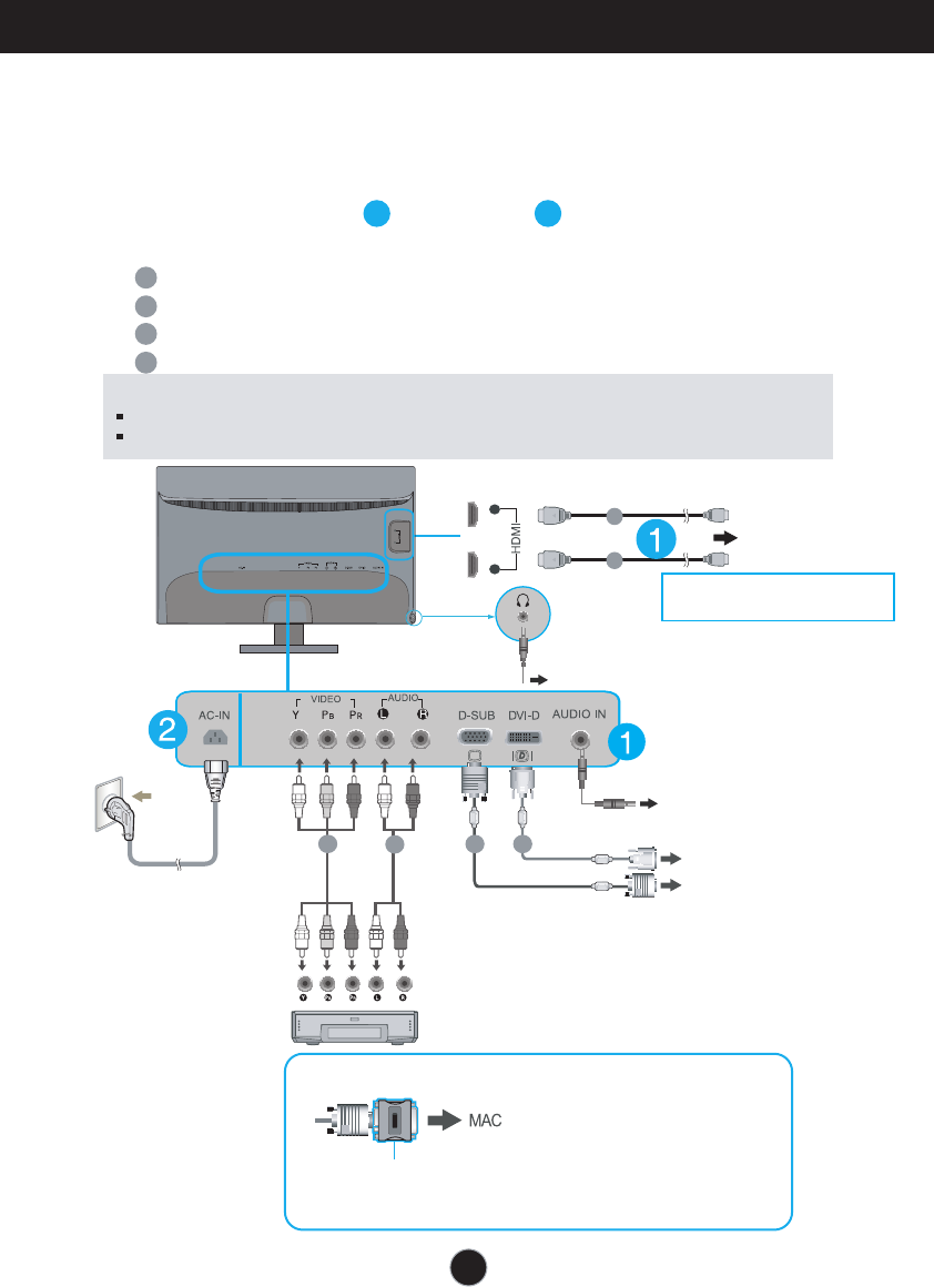
Connecting the Display
A
B
Connect DVI-D(Digital signal) Cable
Connect D-sub(Analog signal) Cable
C
D
Connect VIDEO and AUDIO Cable
Connect HDMI Cable (HDMI1,HDMI2)
1.
Before setting up the monitor, ensure that the power to the monitor, the computer
system, and other attached devices is turned off.
2.
Connect signal input cable and power cord in order, then tighten the screw
of the signal cable.
Connecting with the PC
12
NOTE
This is a simplified representation of the rear view.
This rear view represents a general model; your display may differ from the view as shown.
PC
PC
A
B
Wall-outlet type
Varies according to model.
DVI-D (This feature is not available in all countries.)
DVD player or others which have component port
12
Headphone/Earphone output
Mac adapter : For Apple Macintosh use, a separate plug adapter
is needed to change the 15 pin high density (3 row) D-sub VGA
connector on the supplied cable to a 15 pin 2 row connector.
When using a D-Sub signal input cable connector for Macintosh
AV equipment
(Set-Top Box, DVD, Video,
Video Game Console)
DD
C
C
* HDMI is optimized on the AV equipment.
* Not supported PC.
PC input
Connecting the Display
9
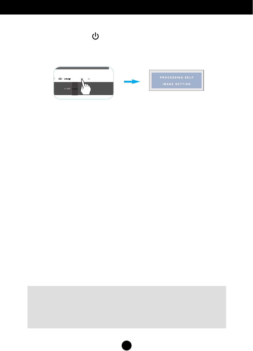
NOTE
‘ Self Image Setting Function’? This function provides the user with optimal display
settings.When the user connects the monitor for the first time, this function automatically adjusts
the display to optimal settings for individual input signals.
‘AUTO/SET’ Function? When you encounter problems such as blurry screen, blurred letters,
screen flicker or tilted screen while using the device or after changing screen resolution, press
the AUTO/SET function button to improve resolution.
3.Press the Power Button ( ) on the front panel to turn the power on. When monitor
power is turned on, the 'Self Image Setting Function' is executed automatically.
(Only Analog Mode)
10
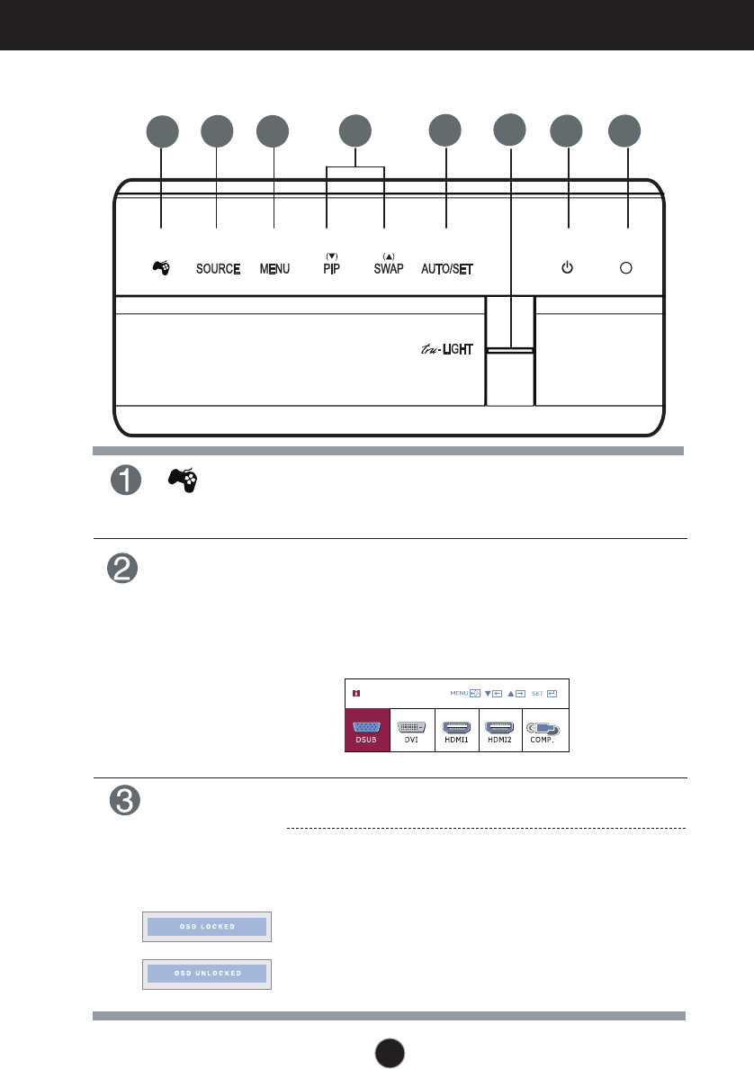
Control Panel Functions
Front Panel Controls
ButtonSOURCE
MENU Button
Use this button to enter or exit the On Screen Display.
OSD LOCKED/UNLOCKED
This function allows you to lock the current control
settings, so that they cannot be inadvertently changed.
Press and hold the MENU button for several seconds.
The message "OSD LOCKED" should appear.
You can unlock the OSD controls at any time by pushing
the MENU button for several seconds. The message
"OSD UNLOCKED" should appear.
Button
Use this button to enter THRU MODE,SRS
TRUSURROUND HD,ARC or AUTO BRIGHT menus.
For more information, refer to page 14.
123568
7
4
When two or more input signals are connected,
first monitor automatically detects one signal as
main input, then you can select the input signal
(DSUB/DVI/HDMI1/HDMI2/COMPONENT) you
want.
INPUT
11
Control Panel Functions
Buttons
Use these buttons to select or adjust functions in the On
Screen Display.
Use this button you can directly use PIP function.
You can use PIP menu to select PIP input.
For more information, refer to page 21.
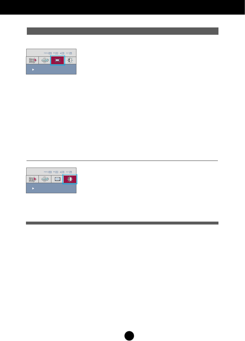
Use this button to select LED light mode,
GAME,MOVIE,MUSIC or turn off the LED
light.
Tru-LIGHT
Button
Use this button to turn the display on or off.
Power
Power Indicator
The power indicator stays blue if the display is running
properly (On Mode). If the display is in Sleep Mode
(Energy Saving), the power indicator is blinking blue.
PIP
SWAP
When two input signals are connected, one is main input,
the other is PIP input. You can use this button to exchange
the main input and PIP input.
AUTO/SET
Use this button to enter a selection in the On Screen
Button
Display.
AUTO IMAGE ADJUSTMENT
When adjusting your display settings, always press
the AUTO/SET button before entering the O
. (Only DSUB and component mode)
n Screen
Display(OSD)
This will automatically adjust your display image to the
ideal settings for the current screen resolution size
(display mode).
The best display mode is
1920 x 1080
TRU-LIGHT
OFF
MUSIC
MOVIE
GAME
12
On Screen Display (OSD) Control Adjustment
Screen Adjustment
Making adjustments to the image size, position and operating
parameters of the display is quick and easy with the On Screen
Display Control system.
A short example is given below to familiarize you with the use of the
controls. The following section is an outline of the available
adjustments and selections you can make using the OSD.
Pops up the
menu screen
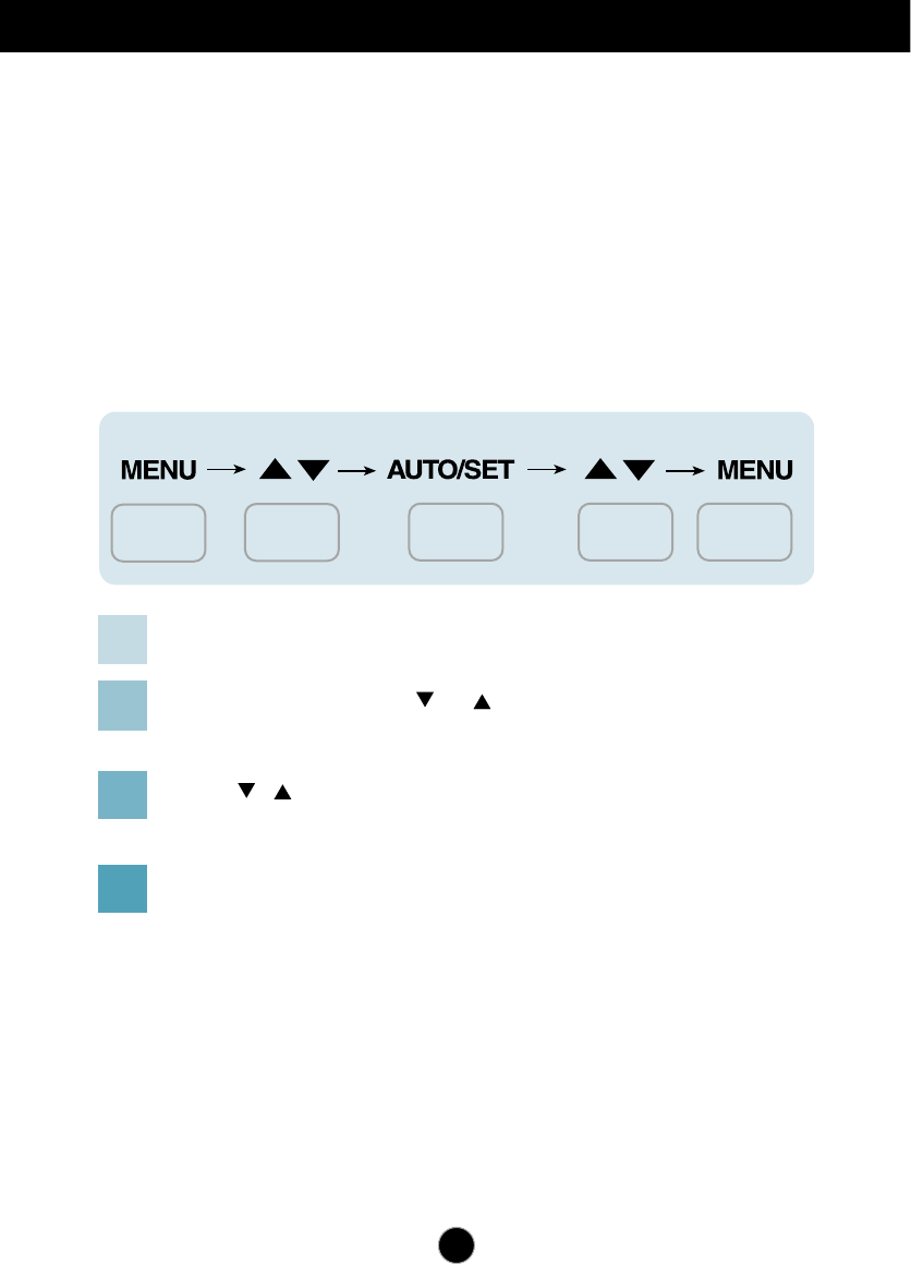
To make adjustments in the On Screen Display, follow these steps:
Move where
you want to
adjust
Select a
menu icon
Adjust the
status
Exit from the
menu screen.
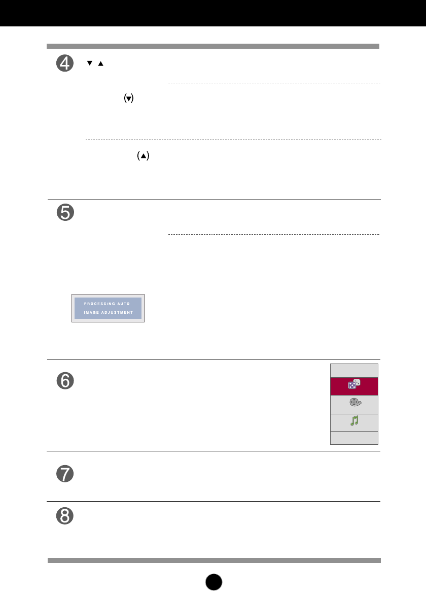
Press the MENU Button, then the main menu of the OSD appears.
To access a control, use the or Buttons. When the icon you want
becomes highlighted, press the AUTO/SET Button.
Use the / Buttons to adjust the image to the desired level.
Use the AUTO/SET Button to select other sub-menu items.
Press the MENU Button once to return to the main menu to select another
function. Press the MENU Button twice to exit from the OSD.
1
2
3
4
NOTE
The order of icons may differ depending on the model (13~21 ).
On Screen Display(OSD) Selection and Adjustment
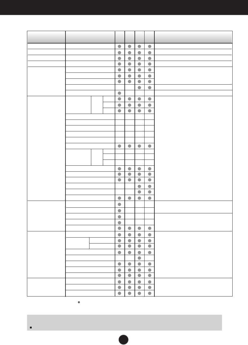
The following table indicates all the On Screen Display control, adjustment,
and setting menus.
: Adjustable A : DSUB Input
D : DVI Input
H : HDMI Input
C : COMPONENT Input
Main menu Sub-menu A D H C Reference
To adjust screen color mode
BRIGHTNESS
CONTRAST
GAMMA
BLACK LEVEL
WHITE BALANCE
COLOR TEMP
sRGB
6500K
PRESET
9300K
RED
GREEN
BLUE
HUE
SATURATION
COLOR RESET
HORIZONTAL
VERTICAL
CLOCK
PHASE
SHARPNESS
OSD
POSITION
HORIZONTAL
VERTICAL
LANGUAGE
VOLUME
OVERSCAN
LIGHTING LEVEL
POWER INDICATOR
FACTORY RESET
PIP ON/OFF
PIP INPUT
PIP POSITION
COLOR TEMP
sRGB
6500K
USER
9300K
RED
GREEN
BLUE
HUE
SATURATION
COLOR RESET
To adjust the brightness, contrast and
gamma of the screen
To
To adjust screen staus for operating environment
set offset level
Use Frame-Buffer to prevent picture delay
Use 3D surround for live sound effect
Use aspect ratio control
To control screen brightness automatically
To adjust the position of the screen
To costomize the screen status for a
user's operating environment
To adjust PIP function
To improve the clarity and stability of the
screen
SETUP
PIP
TRACKING
COLOR
PICTURE
AUTO BRIGHT
ARC
SRS TRUSURROUND HD
THRU MODE
13
G-MODE
THRU MODE ON
G-MODE
SRS TRUSURROUND HD
On Screen Display(OSD) Selection and Adjustment
Menu Name
G-MODE
Icons MENU : Save & Exit
, : Move
Sub-menu Name
THRU MODE ON
Main menu Sub menu Description
THRU MODE ON
Not use the Frame-Buffer memory to prevent
the picture delay.It can use in GAME MODE to
prevent picture delay.
OFF
Using the Frame-Buffer memory to control PIP,
ARC function.
If user select “THRU MODE ON” with “PIP ON”,
“THRU MODE” will turn "OFF" automatically.
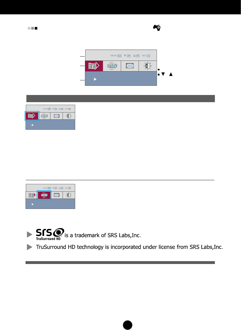
SRS TRUSURROUND HD
The OSD screen will appear when you press the button on the front of
the monitor.
ON
Turn on SRS function, offer 3D surround for live
sound effect.
OFF
Turn off SRS function.
14
G-MODE
ARC FULL
G-MODE
AUTO BRIGHT ON
On Screen Display(OSD) Selection and Adjustment
Main menu Sub menu Description
ARC
AUTO BRIGHT
1:1
The picture will be displayed depends on Input
resolution.No Scaling.If 640x480 resolution input,
the picture will just display 640x480 size even
though the 1920x1080 size panel.
Original
The picture will be displayed with input resolution
ratio scaling. If 640x480 resolution input, the picture
will keep at 4:3 ratio scaling.
FULL
The picture will be displayed with Full size.
To control screen brightness automatically.
When ON is selected, this function adjusts the
screen brightness automatically, depending on
the display data levels, to provide optimal viewing
conditions. When OFF is selected, this function
is turned off.
15
On Screen Display(OSD) Selection and Adjustment
Sub-menus
NOTE
OSD (On Screen Display) menu languages on the monitor may differ from the manual.
You were introduced to the procedure of selecting and adjusting an item
using the OSD system. Listed below are the icons, icon names, and icon
descriptions of the all items shown on the Menu.
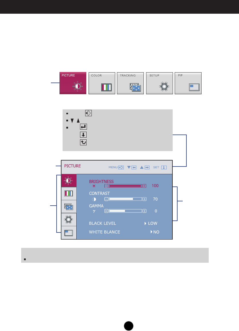
Press the MENU Button, then the main menu of the OSD appears.
Menu Name
Icons
Button Tip
MENU : Exit
: Adjust (Decrease/Increase)
SET : Enter
: Select another sub-menu
:Restart to select sub-menu
Main Menu
16
On Screen Display(OSD) Selection and Adjustment
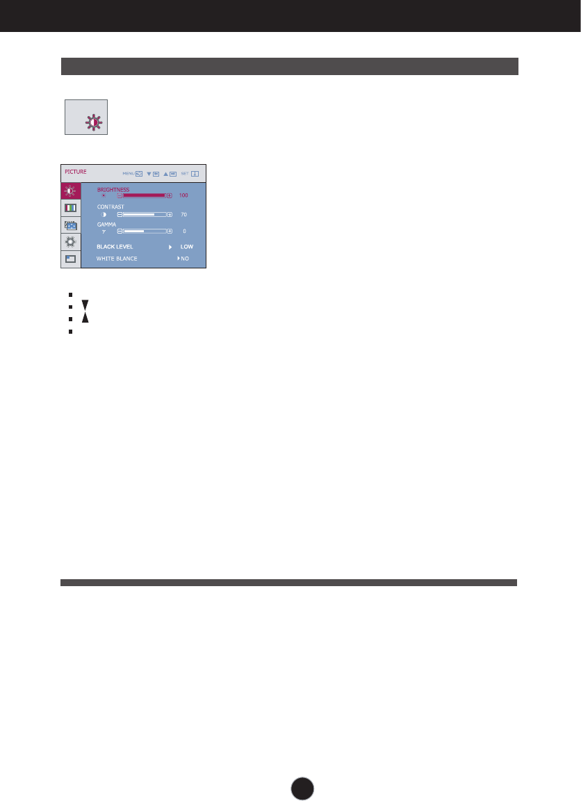
Main menu Sub menu Description
BRIGHTNESS
CONTRAST
GAMMA
BLACK LEVEL
To adjust the brightness of the screen.
To adjust the contrast of the screen.
Set your own gamma value. : -50/0/50
On the monitor, high gamma values
display whitish images and low gamma
values display high contrast images.
You can set the offset level. If you select
'HIGH', the screen will be bright and if you
select ‘LOW’, the screen will be dark.
(only for HDMI input)
* Offset? As the criteria for video signal, it is the
darkest screen the monitor can show.
PICTURE
PICTURE
MENU : Exit
: Decrease
: Increase
SET : Select another sub-menu
WHITE
If the output of the video card is different
the required specifications, the color
level may deteriorate due to video
signal distortion. Using this function, the
signal level is adjusted to fit into the
standard output level of the video card
in order to provide the optimal image.
Activate this function when white and
black colors are present in the screen.
(only for DSUB input)
BALANCE
17
On Screen Display(OSD) Selection and Adjustment
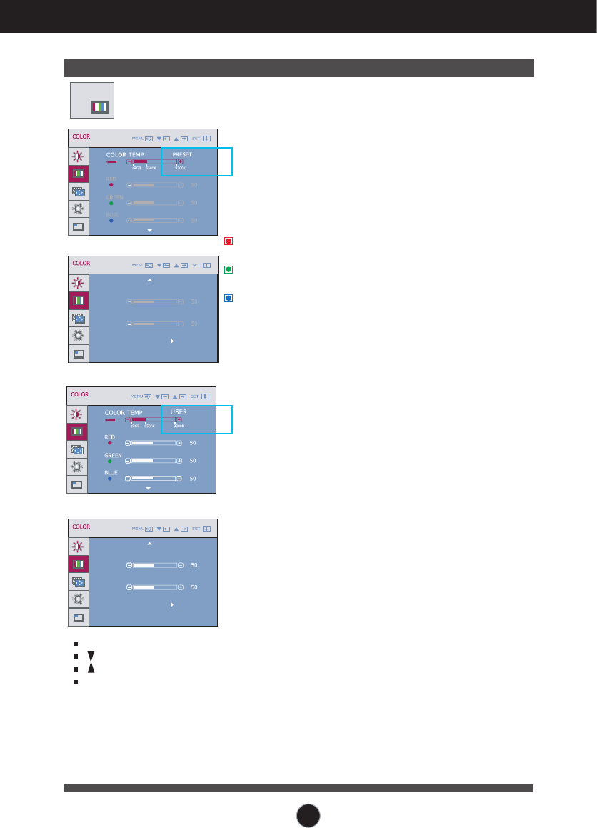
Main menu Sub menu Description
COLOR
COLOR
PRESET
• sRGB: Set the screen color to fit the
SRGB standard color
specification.
• 6500K: Slightly reddish white.
• 9300K: Slightly bluish white.
USER
RED
Set your own red color levels.
GREEN
Set your own green color levels.
BLUE
Set your own blue color levels.
HUE
Set your own HUE levels.
SATURATION
Set your own saturation levels.
COLOR RESET
Pestore “PICTURE” and “COLOR”
default settings.
HUE
SATURATION
COLOR RESET NO
HUE
SATURATION
COLOR RESET NO
MENU : Exit
: Decrease
: Increase
SET : Select another
sub-menu
18
On Screen Display(OSD) Selection and Adjustment
Main menu Sub menu Description
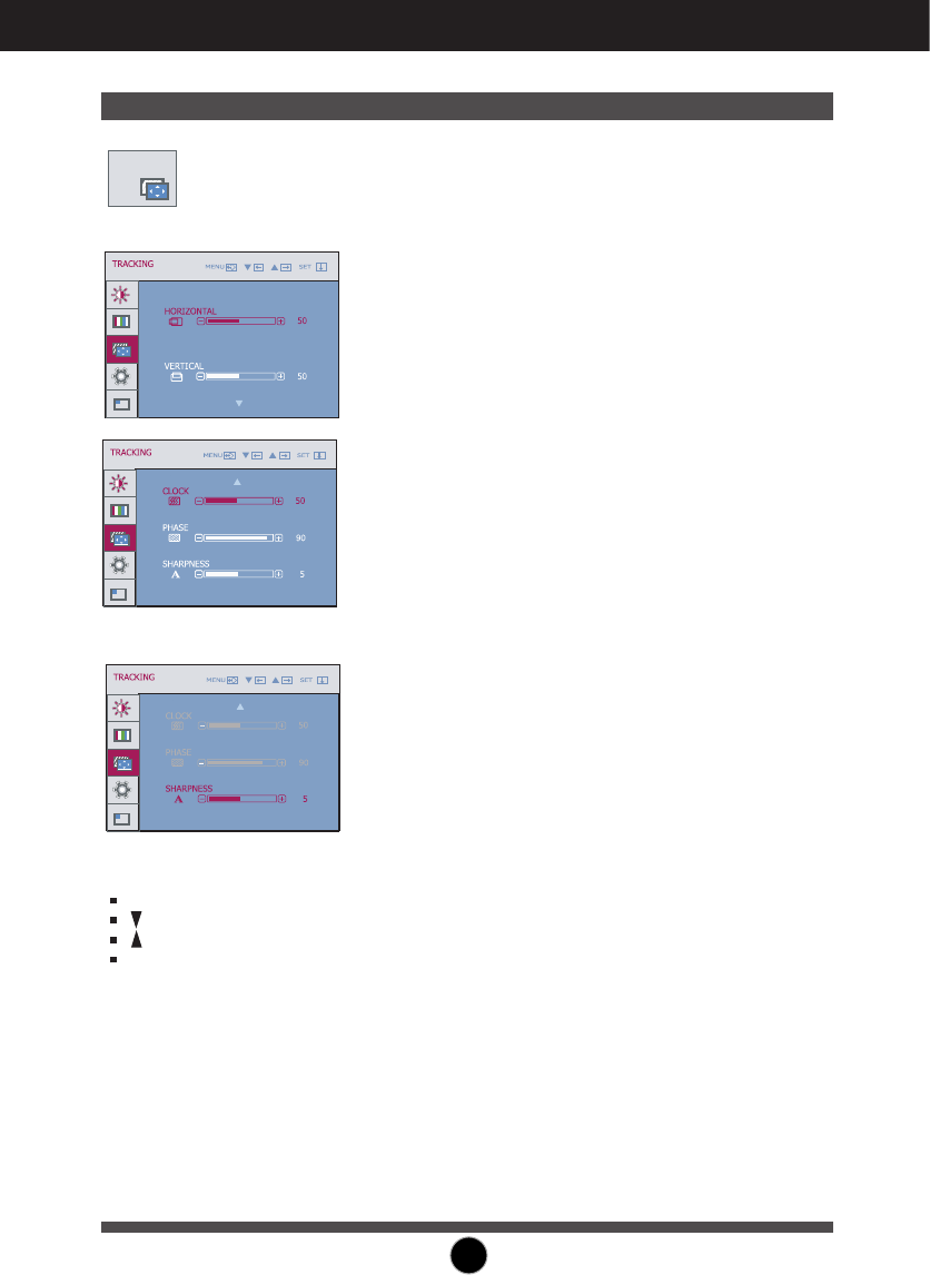
TRACKING
TRACKING
HORIZONTAL To move image left and right.
VERTICAL To move image up and down.
CLOCK
To minimize any vertical bars or
stripes visible on the screen
background.
The horizontal screen size will also
change.
PHASE
To adjust the focus of the display.
This item allows you to remove
any horizontal noise and clear or
sharpen the image of characters.
MENU : Exit
: Decrease
SHARPNESS
To adjust the clearness of the
: Increase
screen.
SET : Select another sub-menu
DSUB input
DVI,HDMI,COMPONET input
19
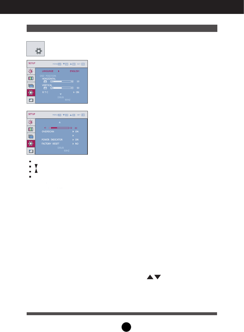
Restore all factory default settings except
"LANGUAGE."
Press the , buttons to reset immediately.
On Screen Display(OSD) Selection and Adjustment
Main menu Sub menu Description
If this does not improve the screen image, restore the factory default settings.
If necessary, perform the white balance function again. This function will be enabled only when
the input signal is an analog signal.
SETUP
To choose the language in which the
control names are displayed.
To adjust position of the OSD window
on the screen.
LANGUAGE
OSD
POSITION
OVERSCAN
FACTORY
RESET
To select the range of output image for
DTV timing in HDMI input.
(only for HDMI input)
Recommend overscan function to turn
on when connect AV equipment.
POWER
INDICATOR
1920 x 1080
VOLUME
LIGHTING LEVEL
1920 x 1080
3
RTC
If you set ON, you enable the Response
Time Control function.
If you set OFF, you disable the
Response Time Control function.
SETUP
MENU : Exit
: Adjust
: Adjust
SET : Select another sub-menu
Use this function to set the power
indicator on the front side of the monitor
to ON or OFF.
If you set OFF, it will go off.
If you set ON at any time, the power
indicator will automatically be turned on.
VOLUME
To adjust the volume of headphone/
Earphone.
LIGHTING
LEVEL
The White LED will move from center of the
PCB depends on Sound input signal level.
If sound signal level is lower than Threshold
level,the LED cannot operate.
About LIGHTING LEVEL,you can change
from 0 to 10.
If No sound input, the LED has no action.
20
On Screen Display(OSD) Selection and Adjustment
Main menu Sub menu Description
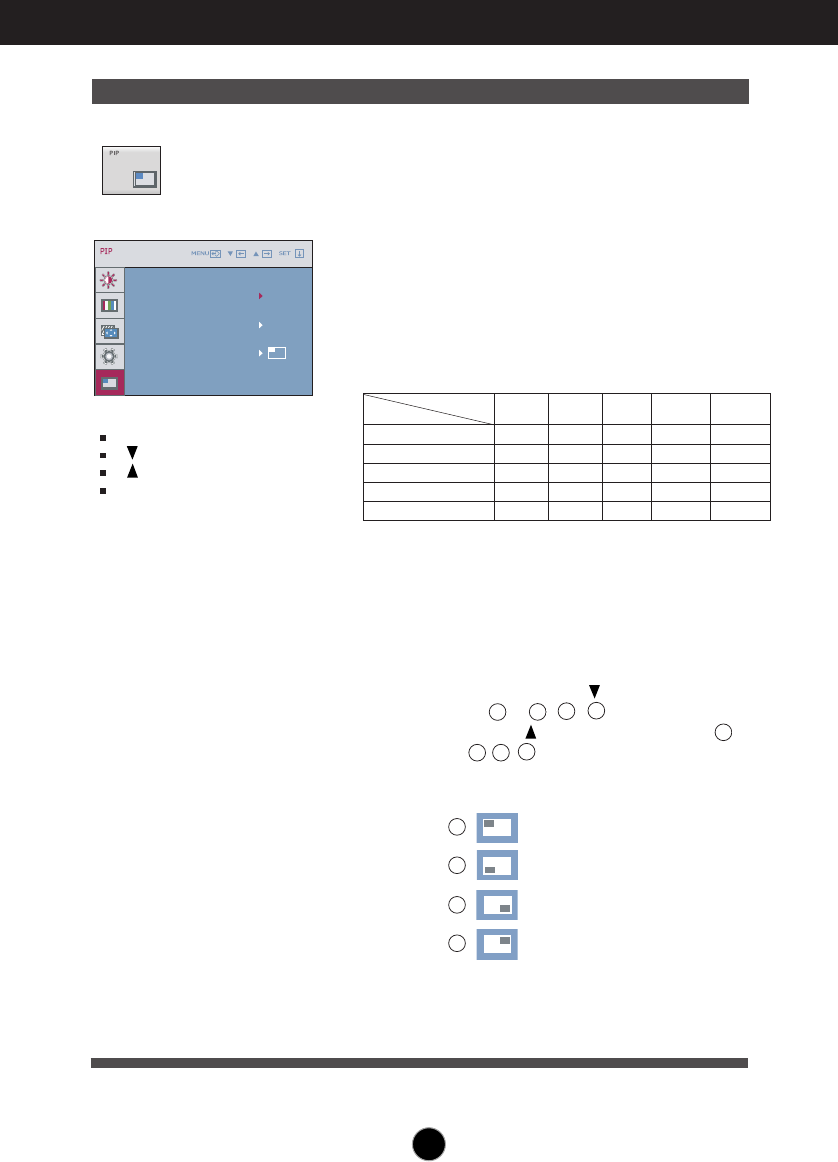
PIP
PIP ON/OFF
PIP POSITION Select the PIP display location. Every
time you touch the button, it will move
from to , , . Every time you
1234
press the button, it will move from
1
to , , . You can use this menu to
43 2
select the PIP display location you want.
1
: Top left
2
: Bottom left
3
: Bottom right
4
: Top right
*It operates only when PIP is on.
MENU : Exit
: Adjust
: Adjust
AUTO/SET
: Select another
sub-menu
To select PIP on or off.
* It supports only for HDMI input in RGB
(
D-sub analog signal)
mode.
* The combinations of main screen and
sub-screen (PIP) available are as shown
below:
Main screen
Sub-screen (PIP)
X-OOO
HDMI #1
OOOX-
RGB
OOO-X
Component
OO-OO
DVI
-XOOO
HDMI #2
HDMI #2HDMI #1DVI
Compon
ent
RGB
X-OOO
HDMI #1
OOOX-
RGB
OOO-X
Component
OO-OO
DVI
-XOOO
HDMI #2
HDMI #2HDMI #1DVI
Compon
ent
RGB
PIP INPUT Select PIP input.
21
PIP ON/OFF
PIP INPUT
PIP POSITION
ON
DVI
Troubleshooting
No image appears
Check the following before calling for service.
No image appears
Do you see a "OSD LOCKED" message on the screen?
●Is the power cord of the
display connected?
●Is the power indicator
light on?
●Is the power indicator
flickering?
●Do you see an "OUT OF
RANGE" message on
the screen?
●Do you see a "CHECK
SIGNAL CABLE"
message on the
screen?
•
Check and see if the power cord is connected
properly to the power outlet.
•
Press the Power button.
•
If the display is in power saving mode, try moving
the mouse or pressing any key on the keyboard to
bring up the screen.
• Try to turn on the PC
.
•
This message appears when the signal from the
PC (video card) is out of horizontal or vertical
frequency range of the display. See the
'Specifications' section of this manual and
configure your display again.
•
This message appears when the signal cable
between your PC and your display is not
connected. Check the signal cable and try again.
• You can secure the current control settings,
so that they cannot be inadvertently changed.
You can unlock the OSD controls at any time
by pushing the MENU button for several
seconds: the message
“OSD UNLOCKED” will appear.
●
Do you see “OSD
LOCKED” when you
push MENU button?
22
Troubleshooting
Display image is incorrect
●Display Position is
incorrect.
●On the screen
background, vertical
bars or stripes are
visible.
●Any horizontal noise
appearing in any
image or characters
are not clearly
portrayed.
•
Press the AUTO/SET button to automatically
adjust your display image to the ideal setting.
If the results are unsatisfactory, adjust the image
position using the H position and V position icon
in the on screen display.
•
Press the AUTO/SET button to automatically
adjust your display image to the ideal setting.
If the results are unsatisfactory, decrease the
vertical bars or stripes using the CLOCK icon in
the on screen display.
•
Press the AUTO/SET button to automatically
adjust your display image to the ideal setting.
If the results are unsatisfactory, decrease the
horizontal bars using the PHASE icon in the on
screen display.
•
Check Control Panel --> Display --> Settings
and adjust the display to the recommended
resolution or adjust the display image to the ideal
setting. Set the color setting higher than 24 bits
(true color).
Important
Check Control Panel --> Display --> Settings and see if the frequency or the
resolution were changed. If yes, readjust the video card to the recommend
resolution.
If the recommended resolution (optimal resolution) is not selected, letters may
be blurred and the screen may be dimmed, truncated or biased. Make sure to
select the recommend resolution.
The setting method can differ by computer and O/S (Operation System),
and resolution mentioned above may not be supported by the video card
performance. In this case, please ask to the computer or the video card
manufacturer.
23
Troubleshooting
Have you installed the display driver?
●
Have you installed the
display driver?
●
Do you see an
"Unrecognized monitor,
Plug&Play (VESA DDC)
monitor found"
message?
•
Be sure to install the display driver from the display
driver CD (or diskette) that comes with your
display. Or, you can also download the driver from
our web site: http://www.lge.com.
•
Make sure to check if the video card supports
Plug&Play function.
Display image is incorrect
●The screen color is
mono or abnormal.
●The screen blinks.
•
Check if the signal cable is properly connected
and use a screwdriver to fasten if necessary.
•
Make sure the video card is properly inserted in
the slot.
•
Set the color setting higher than 24 bits (true color)
at Control Panel - Settings.
•
Check if the screen is set to interlace mode and if
yes, change it to the recommend resolution.
The Audio function is not working
●
Picture OK & No sound.
• Check whether volume is "0".
• Check sound muted.
• HDMI cable installed properly.
• Head phone cable installed properly.
• Check sound format. Not supply to compressed
sound format.
24
Specifications
NOTE
Information in this document is subject to change without notice.
Display
Sync Input
Video Input
Resolution
Plug&Play
Power
Consumption
Dimensions
&Weight
Tilt Range
Power Input
Environmental
Conditions
Stand Base
Power cord
23.0 inches (58.4 cm) Flat Panel Active matrix-TFT LCD
Anti-Glare coating
Visible diagonal size: 58.4 cm
0.265*0.265 mm pixel pitch
Horizontal Freq.
Vertical Freq. Analog,Digital : 56 - 75 Hz (Automatic)
HDMI : 56 - 61 Hz (Automatic)
Analog,Digital : 30 - 83 KHz (Automatic)
HDMI : 30 - 83 KHz (Automatic)
Input Form Separate Sync, Positive/Negative
Digital (HDCP)
Signal Input 15 pin D-Sub Connector
DVI - D connector (Digital)
19 pin HDMI Connector
Input Form Analog (0.7 Vp-p/ 75 ohm), Digital, HDMI
Max VESA 1920 x 1080 @60 Hz
Recommend 1920 x 1080 @60 Hz
DDC 2B (Analog,Digital,HDMI)
On Mode : 42 W(Typ.)
1.4 W(DSUB/DVI)
Sleep Mode
Off Mode 1 W
With Stand Without Stand
Width 55.55 cm / 21.87 inches 55.55 cm / 21.87 inches
Height 41.92 cm / 16.50 inches 40.95 cm / 16.12 inches
Depth 20.59 cm / 8.10 inches 7.33 cm / 2.88 inches
Net 5.1 kg (11.25 lbs)
Tilt -5°~15°
AC 100-240V~ 50/60Hz 1.0A
Operating Conditions
Temperature 10°C to 35 °C
Humidity 10 % to 80 % non-Condensing
Storage Conditions
Temperature -20°C to 60 °C
Humidity 5 % to 90 % non-Condensing
Attached( ), Detached ( O )
Wall-outlet type
25

Specifications
Preset Modes (Resolution)
Display Modes (Resolution) Horizontal Freq. (kHz) Vertical Freq. (Hz)
* Recommend Mode
DSUB/DVI Timing
Display Modes (Resolution) Horizontal Freq. (kHz) Vertical Freq. (Hz)
1
2
3
4
5
6
7
8
480P
576P
720P
720P
1080i
1080i
1080P
1080P
31.50
31.25
37.50
45.00
28.12
33.75
56.25
67.50
60
50
50
60
50
60
50
60
HDMI Timing
1
2
3
4
5
6
7
8
9
10
11
12
13
*14
640 x 350
720 X 400
640 x 480
640 x 480
800 x 600
1024 x 768
1024 x 768
1152 x 864
1280 x 1024
1280 x 1024
1680 x 1050
1680 x 1050
31.469
31.468
31.469
37.500
37.879
48.363
60.123
67.500
63.981
79.976
64.674
65.290
70
70
60
75
60
800 x 600 46.875 75
60
75
75
60
75
60
60
1920 x 1080 67.500 60
26

Specifications
Preset Modes (Resolution)
Display Modes (Resolution) Horizontal Freq. (kHz) Vertical Freq. (Hz)
1
2
3
4
5
6
7
8
480i
576i
480P
576P
720P
720P
1080i
1080i
15.75
15.62
31.50
31.25
37.50
45.00
28.12
33.75
60
50
60
50
50
60
50
60
Component Video Timing
Indicator
On Mode
Sleep Mode
Off Mode
Blue
Blue Blinking
Off
LED Color
MODE
27
Installing the Wall mount plate
This monitor satisfies the specifications of the Wall mount plate
or the interchange device.
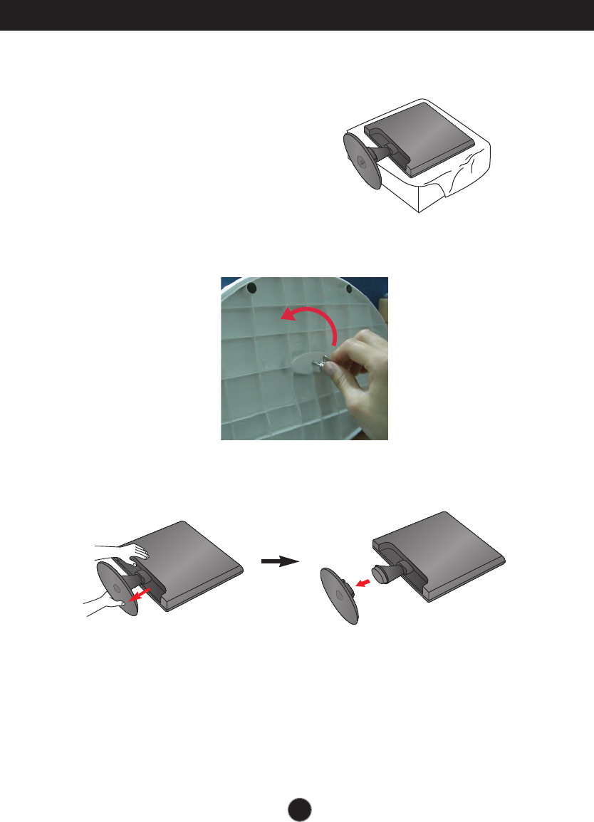
1. Place the monitor face down on the soft cloth.
3.
Pull out the Stand Base to remove.
2.To disconnect the Stand Base from the Stand Body, unfold the screw handle and
turn it to the left.
28
29
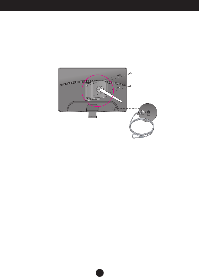
Installing the Wall mount plate
4.
Install the Wall mount plate.
Wall mount plate(Separate purchase)
This is stand-type or wall mount type and is
connectable with Wall mount plate.
Please refer to the installation guide for more details,
which is provided when Wall mount plate is
purchased.
Kensington Security Slot
Connected to a locking cable that
can be purchased separately at
most computer stores.

Digitally yours