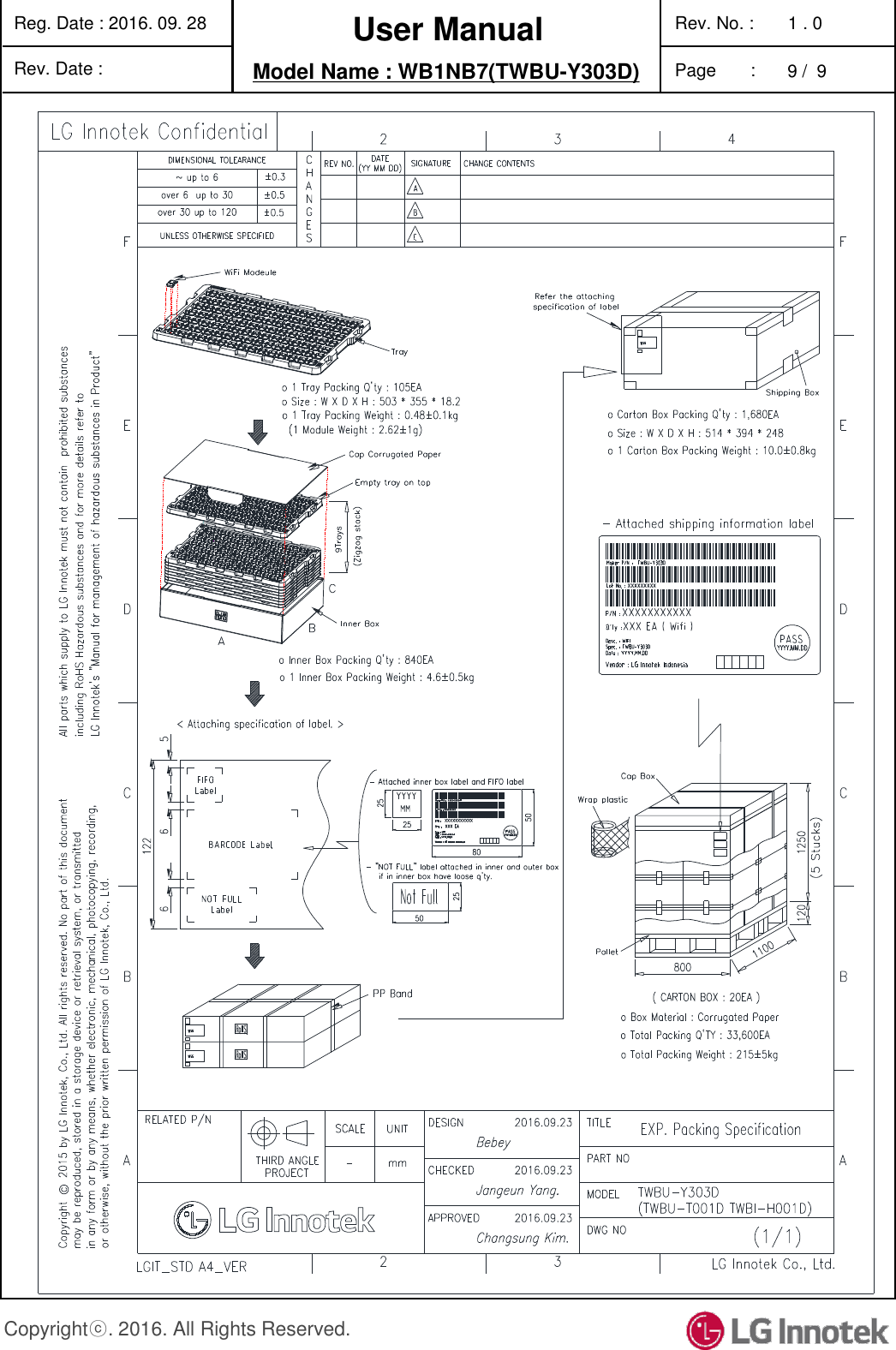
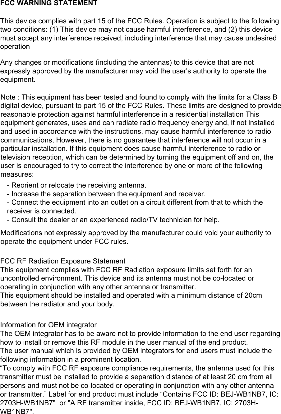
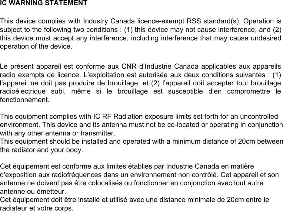
LG Electronics USA WB1NB7 Bluetooth Module User Manual SPECIFICATION

LG Electronics USA Bluetooth Module SPECIFICATION

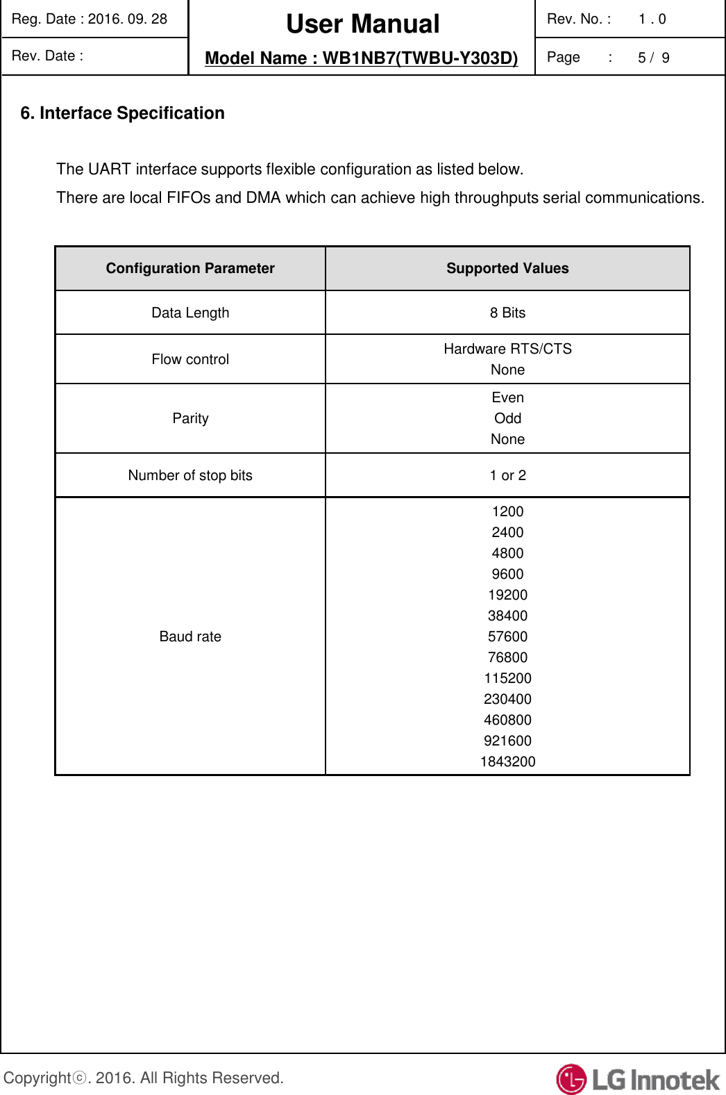
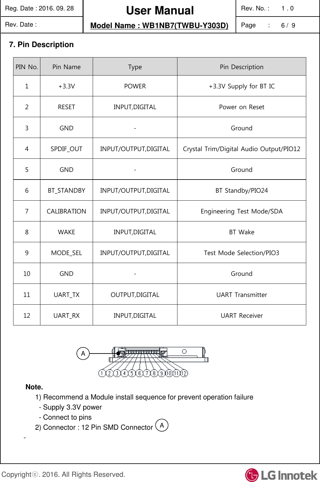
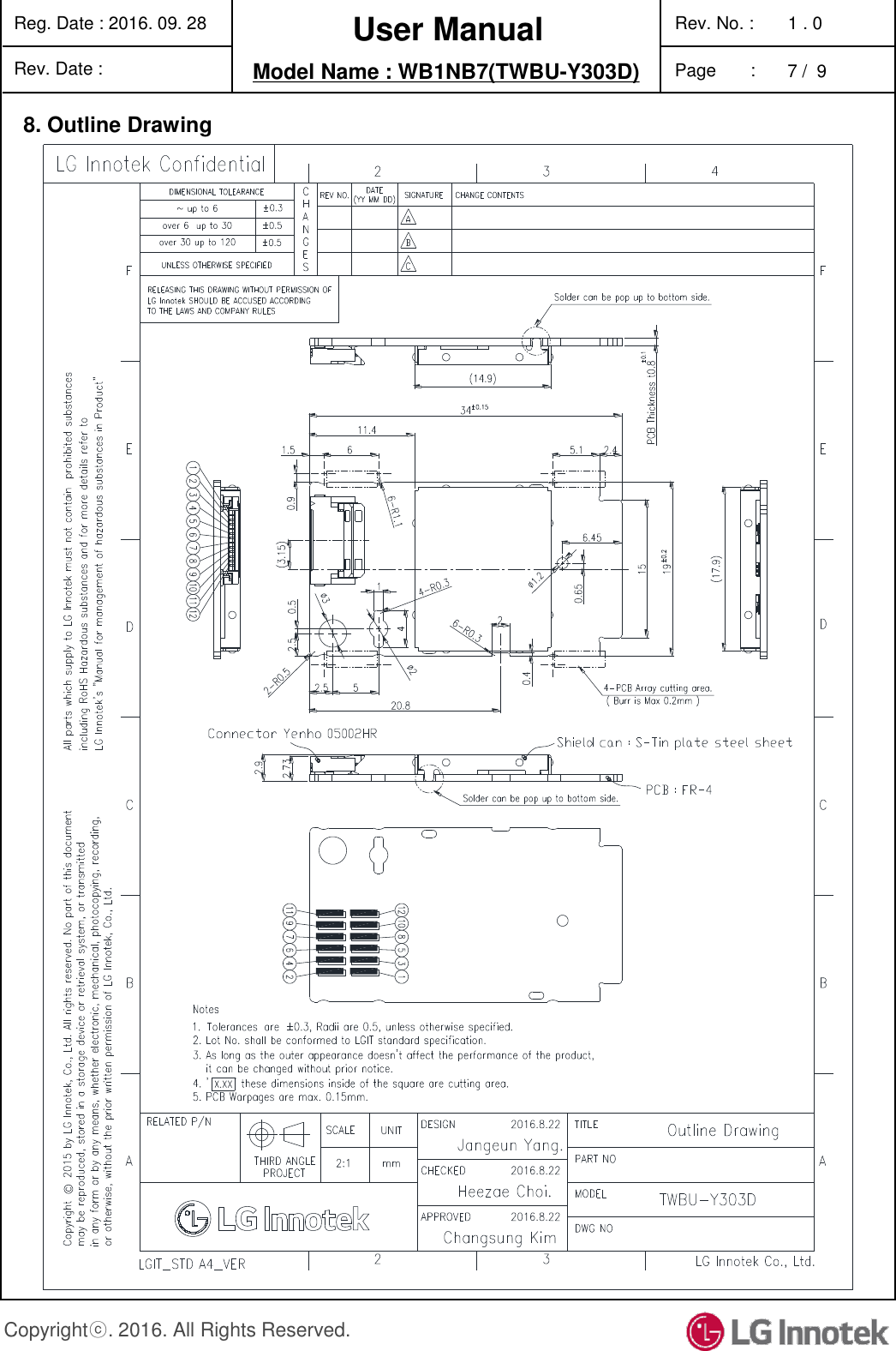
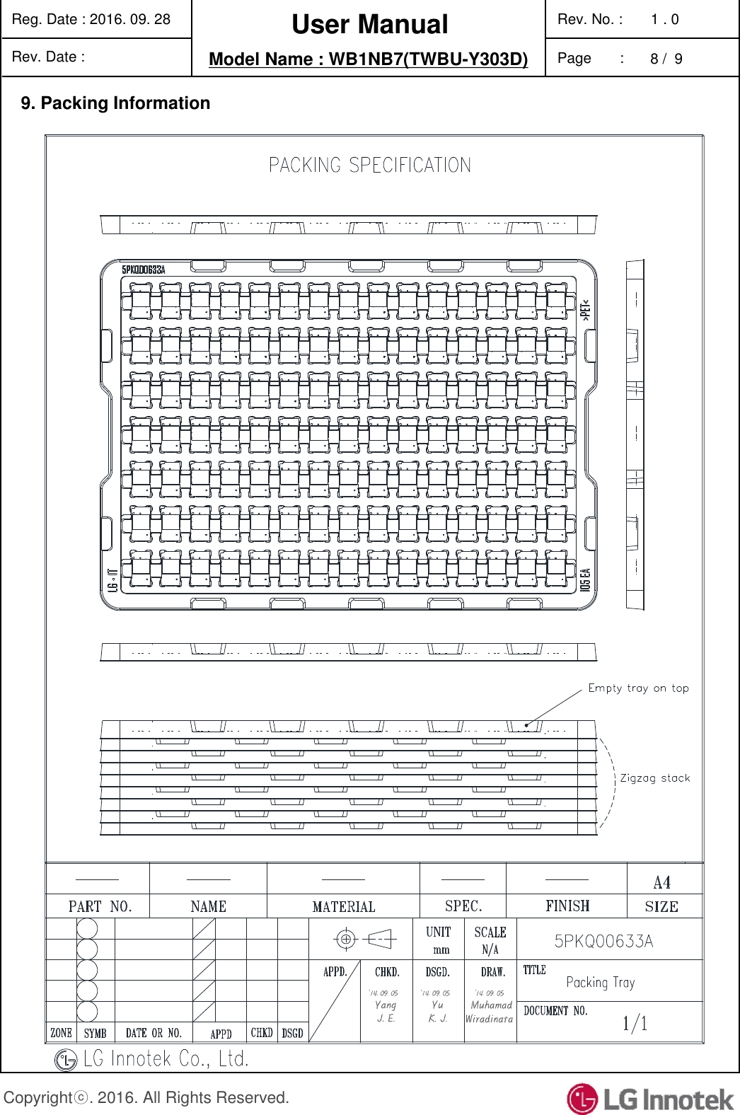
User Manual_WB1NB7_Rev1

User Manual The information contained herein is the exclusive property of LG Innotek and shall not be distributed, reproduced or disclosed in whole or no in part without prior written permission of LG Innotek. Product Name  :  Bluetooth 4.2 Module Model Name     : WB1NB7 (TWBU-Y303D)
User Manual Reg. Date : 2016. 09. 28    Model Name : WB1NB7(TWBU-Y303D) Rev. Date :   Rev. No. :       1 . 0 Page       :   1 /  9 Copyrightⓒ. 2016. All Rights Reserved. Table of Contents No  Description                                                                                                                    Page 1.  Features …………….…………………………………………………....…………...  2 2. Module Photo  …..……………………………………………………….……………  2 3. Block Diagram .. ………………………………………………………………………  3 4.  Storage Conditions ….………………………………………………………………..  4 5.  Operating Conditions ….……………..……………………………………….……...  4 6. Interface Specification ……………..………………………………………….……...  5 7.  Pin Description ………..……………………………………………………………….  6 8.  Outline Drawing    ……………………………………………………………………..  7 9.  Packing Information   ………………………………………………………….………  8
User Manual Reg. Date : 2016. 09. 28    Model Name : WB1NB7(TWBU-Y303D) Rev. Date :   Rev. No. :       1 . 0 Page       :   2 /  9 Copyrightⓒ. 2016. All Rights Reserved. 1. Features      - Complied with Bluetooth 4.2 specification with EDR function      - Internal printed antenna on PCB      - UART with maximum rate of 4Mbps interface      - 12pin SMD connector (connected with FFC)      - Size 34 x 19 x 2.9 mm       - Applied  Airoha AB1520 for Main chipset       - RoHS compliant 2. Module Photo   < TOP  View >                                            < Bottom  View >
User Manual Reg. Date : 2016. 09. 28   Model Name : WB1NB7(TWBU-Y303D) Rev. Date : Rev. No. :       1 . 0 Page       :   4 /  9 Copyrightⓒ. 2016. All Rights Reserved. 5. Operating ConditionsParameter  Min  Typ  Max  Unit Ambient Temperature  0  -  +60  ℃ Operating  Humidity (40℃)  -  -  85  % Supply Voltage  3.15 3.3 3.45  Vdc 4. Storage ConditionsParameter  Min.  Max.  Unit Storage Temperature  -10  +80  ℃ Storage Humidity (@ 40℃)  -  90  % Caution : The specifications above the Table define levels at which permanent damage to the device can occur. Function operation is not guaranteed under these conditions. Operating at absolute maximum conditions for extend periods can adversely affect the long-term reliability of the device. •Other conditions1) Do not use or store modules in the corrosive atmosphere, especially where chloridegas, sulfide gas, acid, alkali, salt or the like are contained.Also, avoid exposure to moisture.2) Store the modules where the temperatureand relative humidity do not exceed 5 to 40℃ and 20 to 60%.
User Manual Reg. Date : 2016. 09. 28   Model Name : WB1NB7(TWBU-Y303D) Rev. Date : Rev. No. :       1 . 0 Page       :   5 /  9 Copyrightⓒ. 2016. All Rights Reserved. 6. Interface SpecificationConfiguration Parameter  Supported Values Data Length  8 Bits Flow control  Hardware RTS/CTS None Parity Even Odd None Number of stop bits  1 or 2 Baud rate 1200 2400 4800 9600 19200 38400 57600 76800 115200 230400 460800 921600 1843200 The UART interface supports flexible configuration as listed below. There are local FIFOs and DMA which can achieve high throughputs serial communications.
User Manual Reg. Date : 2016. 09. 28   Model Name : WB1NB7(TWBU-Y303D) Rev. Date : Rev. No. :       1 . 0 Page       :   6 /  9 Copyrightⓒ. 2016. All Rights Reserved. 7. Pin DescriptionA PIN No. Pin Name  Type  Pin Description 1  +3.3V  POWER  +3.3V Supply for BT IC 2  RESET  INPUT,DIGITAL  Power on Reset 3  GND  -  Ground 4  SPDIF_OUT  INPUT/OUTPUT,DIGITAL  Crystal Trim/Digital Audio Output/PIO12 5  GND  -  Ground 6  BT_STANDBY  INPUT/OUTPUT,DIGITAL  BT Standby/PIO24 7  CALIBRATION  INPUT/OUTPUT,DIGITAL  Engineering Test Mode/SDA 8  WAKE  INPUT,DIGITAL  BT Wake 9  MODE_SEL  INPUT/OUTPUT,DIGITAL  Test Mode Selection/PIO3 10  GND  -  Ground 11  UART_TX  OUTPUT,DIGITAL  UART Transmitter 12  UART_RX  INPUT,DIGITAL  UART Receiver A  Note. 1) Recommend a Module install sequence for prevent operation failure - Supply 3.3V power  - Connect to pins 2) Connector : 12 Pin SMD Connector  -
User Manual Reg. Date : 2016. 09. 28    Model Name : WB1NB7(TWBU-Y303D) Rev. Date :   Rev. No. :       1 . 0 Page       :   7 /  9 Copyrightⓒ. 2016. All Rights Reserved. 8. Outline Drawing
User Manual Reg. Date : 2016. 09. 28    Model Name : WB1NB7(TWBU-Y303D) Rev. Date :   Rev. No. :       1 . 0 Page       :   8 /  9 Copyrightⓒ. 2016. All Rights Reserved. 9. Packing Information
User Manual Reg. Date : 2016. 09. 28   Model Name : WB1NB7(TWBU-Y303D) Rev. Date : Rev. No. :       1 . 0 Page       :   9 /  9 Copyrightⓒ. 2016. All Rights Reserved.
FCC WARNING STATEMENTThis device complies with part 15 of the FCC Rules. Operation is subject to the following two conditions: (1) This device may not cause harmful interference, and (2) this device must accept any interference received, including interference that may cause undesired operationAny changes or modifications (including the antennas) to this device that are not expressly approved by the manufacturer may void the user's authority to operate the equipment.Note : This equipment has been tested and found to comply with the limits for a Class B digital device, pursuant to part 15 of the FCC Rules. These limits are designed to provide reasonable protection against harmful interference in a residential installation This equipment generates, uses and can radiate radio frequency energy and, if not installed and used in accordance with the instructions, may cause harmful interference to radio communications, However, there is no guarantee that interference will not occur in a particular installation. If this equipment does cause harmful interference to radio or television reception, which can be determined by turning the equipment off and on, the user is encouraged to try to correct the interference by one or more of the following measures: - Reorient or relocate the receiving antenna. - Increase the separation between the equipment and receiver. - Connect the equipment into an outlet on a circuit different from that to which the receiver is connected. - Consult the dealer or an experienced radio/TV technician for help.  Modifications not expressly approved by the manufacturer could void your authority to operate the equipment under FCC rules.FCC RF Radiation Exposure StatementThis equipment complies with FCC RF Radiation exposure limits set forth for an uncontrolled environment. This device and its antenna must not be co-located or operating in conjunction with any other antenna or transmitter.This equipment should be installed and operated with a minimum distance of 20cm between the radiator and your body. Information for OEM integratorThe OEM integrator has to be aware not to provide information to the end user regarding how to install or remove this RF module in the user manual of the end product. The user manual which is provided by OEM integrators for end users must include the following information in a prominent location.“To comply with FCC RF exposure compliance requirements, the antenna used for this transmitter must be installed to provide a separation distance of at least 20 cm from all persons and must not be co-located or operating in conjunction with any other antenna or transmitter.” Label for end product must include “Contains FCC ID: BEJ-WB1NB7, IC: 2703H-WB1NB7"  or "A RF transmitter inside, FCC ID: BEJ-WB1NB7, IC: 2703H-WB1NB7".
IC WARNING STATEMENTThis device complies with Industry Canada licence-exempt RSS standard(s). Operation is subject to the following two conditions : (1) this device may not cause interference, and (2) this device must accept any interference, including interference that may cause undesired operation of the device. Le présent appareil est conforme aux CNR d’Industrie Canada applicables aux appareils radio exempts  de licence. L’exploitation  est autorisée aux  deux conditions suivantes  : (1) l’appareil ne  doit  pas  produire  de brouillage,  et  (2)  l’appareil  doit accepter  tout  brouillage radioélectrique  subi,  même  si  le  brouillage  est  susceptible  d’en  compromettre  le fonctionnement.This equipment complies with IC RF Radiation exposure limits set forth for an uncontrolledenvironment. This device and its antenna must not be co-located or operating in conjunctionwith any other antenna or transmitter.This equipment should be installed and operated with a minimum distance of 20cm between the radiator and your body.Cet équipement est conforme aux limites établies par Industrie Canada en matière d'exposition aux radiofréquences dans un environnement non contrôlé. Cet appareil et son antenne ne doivent pas être colocalisés ou fonctionner en conjonction avec tout autre antenne ou émetteur.Cet équipement doit être installé et utilisé avec une distance minimale de 20cm entre le radiateur et votre corps.

Navigation menu