LG ELECTRONICS LST2200 User Manual lst200 2200 EngUser
LG Electronics, Inc. lst200 2200 EngUser
UserManual.wiki
>
LG ELECTRONICS
>
LST2200 User Manual
Users Manual
Navigation menu
Upload a User Manual
Namespaces
Wiki Guide
HTML
PDF
Info
Views
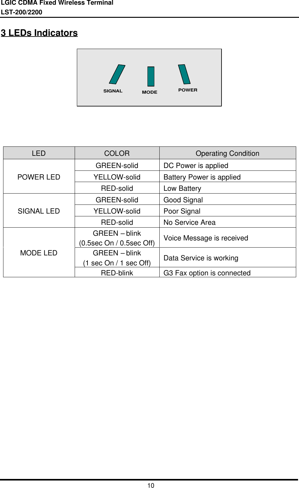
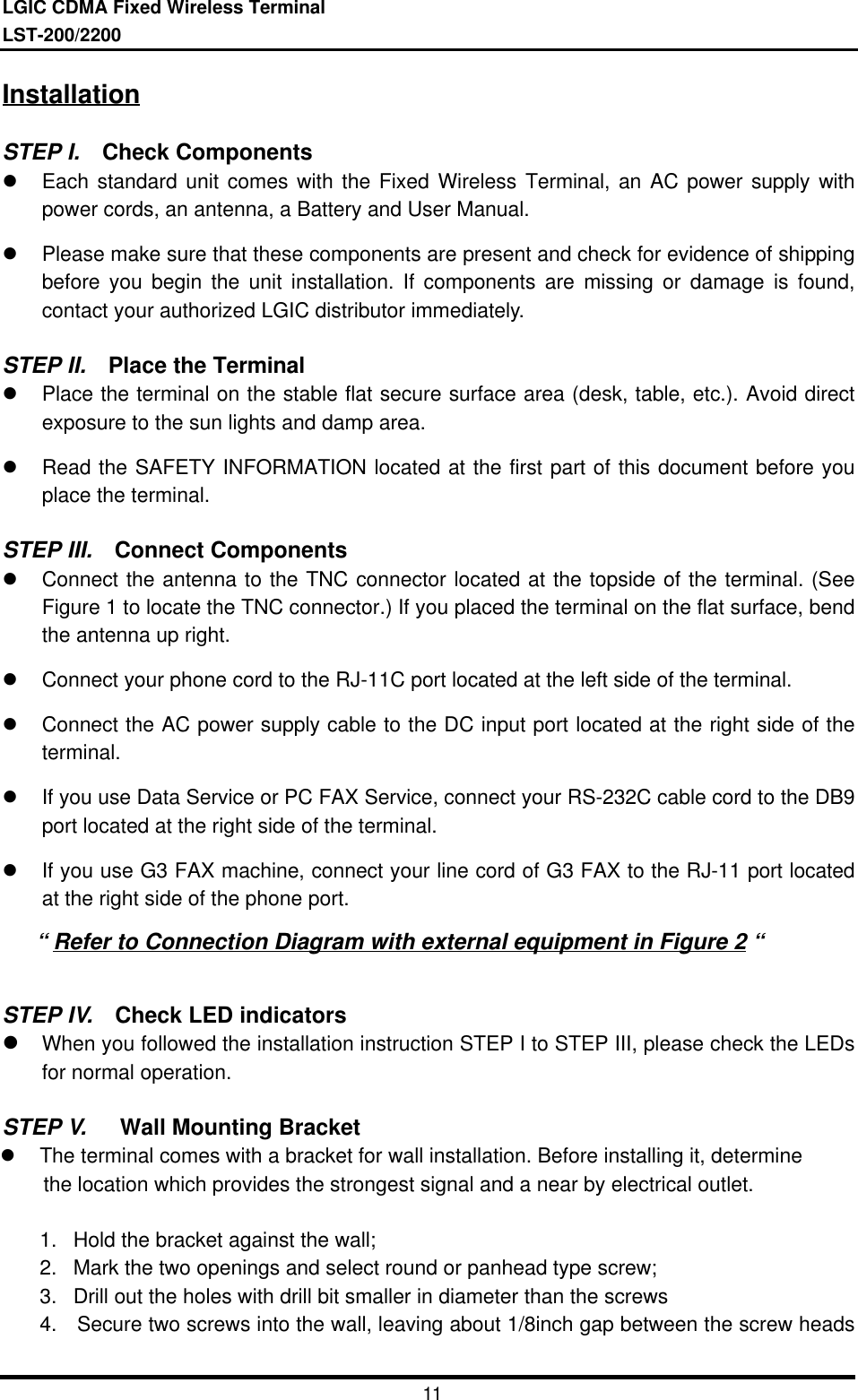
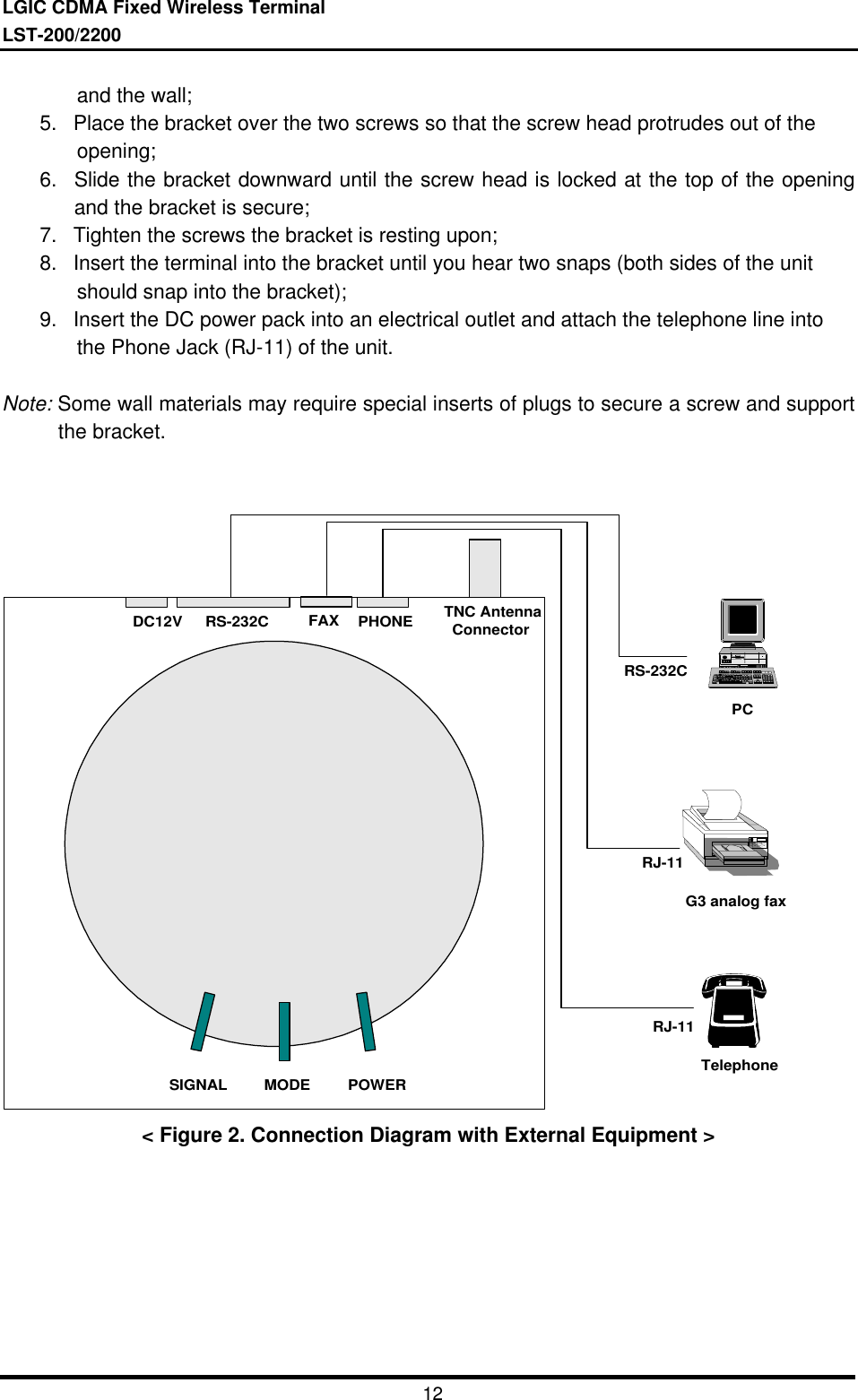
User Manual
Discussion / Help
Navigation