LG 32LD665H User Manual Owner's SAC34134301 5 Edt
55LV555H Owner's Manual SAC34134301_5_edt Most comprehensive of product setup and usage. (English)
37LD665H Owner's Manual SAC34134301_5_edt Most comprehensive of product setup and usage. (English)
32LV555H Owner's Manual SAC34134301_5_edt Most comprehensive of product setup and usage. (English)
37LV555H Owner's Manual SAC34134301_5_edt Most comprehensive of product setup and usage. (English)
32LD665H Owner's Manual File?fileId=KROWM000356324 Most comprehensive of product setup and usage. (English)
2012-03-09
User Manual: LG 32LD665H Owner's Manual Most comprehensive of product setup and usage. (English)
Open the PDF directly: View PDF ![]() .
.
Page Count: 207 [warning: Documents this large are best viewed by clicking the View PDF Link!]
- CD FACE
- COVER
- WARNING / CAUTION
- SAFETY INSTRUCTIONS
- CONTENTS
- FEATURES OF THIS TV
- PREPERATION
- ACCESSORIES
- FRONT PANEL INFORMATION
- BACK PANEL INFORMATION
- STAND INSTRUCTIONS
- CABLE MANAGEMENT
- DESKTOP PEDESTAL INSTALLATION
- SWIVEL STAND
- ATTACHING THE TV TO A DESK
- VESA WALL MOUNTING
- SECURING THE TV TO THE WALL TO PREVENT FALLING WHEN THE TV IS USED ON A STAND
- ANTENNA OR CABLE CONNECTION
- MPI CARD SLOT / PPV CARD INSTALLATION
- EXTERNAL EQUIPMENT SETUP
- WATCHING TV / CHANNEL CONTROL
- USB
- PICTURE CONTROL
- SOUND & LANGUAGE CONTROL
- TIME SETTING
- PARENTAL CONTROL / RATINGS
- APPENDIX
- COMMERCIAL MODE SETUP GUIDE
- Safety Warnings
- IMPORTANT SAFETY INSTRUCTIONS
- Table of Contents
- Commercial Mode Overview
- Pro:Centric Operation
- Installer Remote Control Typical Key Functions
- Master TV Setup
- Installer Menu
- Channel Icons / Custom Text Labels (2-5-4 + MENU Mode)
- Cloning Overview
- USB Cloning Procedures
- Clone Programmer Cloning Procedures
- FTG Mode of Operation Overview
- FTG Mode via CPU
- FTG Mode via EBL (Local Configuration)
- FTG File Manager Utilities Overview
- IP Environment Setup
- Remote Jack Pack / TV Connections & Setup
- Reference
- Upgrading TV/PTC Software using a USB Memory Device
- Downloading a Splash Screen Image
- Power Consumption Settings
- TV Camport Auto Sense Operation
- TV Aux Input Configuration
- b-LAN Setup & Overview
- RJP Model List and Input Auto-sensing Hierarchy
- Resetting Factory Defaults on the TV(s)
- TV Zone Restrictions
- LD660H/LD665H Rear Jack Panel
- LV555H Rear Jack Panel
- Side Connections Panel
- RF Antenna Connection
- Troubleshooting
- Glossary of Terms
- Document Revision History / Notes
- BACK COVER

LED LCD TV / LCD TV
OWNER’S MANUAL
Please read this manual carefully before operating
your set and retain it for future reference.
P/NO : SAC34134301 (1111-REV05) www.lg.com
The model and serial number of the TV is located
on the back and/or on one side of the TV.
Record these numbers below should you ever
need service.
MODEL
SERIAL
32LG710H
37LG710H
42LG710H
32LD650H
37LD650H
42LD650H
47LD650H
55LD650H
32LD655H
37LD655H
42LD655H
32LD660H
37LD660H
42LD660H
32LD665H
37LD665H
42LD665H
32LV555H
37LV555H
42LV555H
47LV555H
55LV555H
LCD TV MODELS LED LCD TV MODELS
1-800-243-0000
1-888-865-3026
1-888-542-2623
USA, Consumer User
USA, Commercial User
CANADA
LG Customer Information Center

2
WARNING / CAUTION
WARNING
RISK OF ELECTRIC SHOCK
DO NOT OPEN
TO REDUCE THE RISK OF ELECTRIC SHOCK
DO NOT REMOVE COVER (OR BACK).
NO USER SERVICEABLE PARTS INSIDE.
REFER TO QUALIFIED SERVICE PERSONNEL.
WARNING
RISK OF ELECTRIC SHOCK
DO NOT OPEN
The lightning flash with arrowhead
symbol, within an equilateral triangle, is
intended to alert the user to the presence of
uninsulated “dangerous voltage” within the
product’s enclosure that may be of sufficient
magnitude to constitute a risk of electric shock
to persons.
WARNING
RISK OF ELECTRIC SHOCK
DO NOT OPEN
The exclamation point within an
equilateral triangle is intended to alert
the user to the presence of important operating
and maintenance (servicing) instructions in the
literature accompanying the appliance.
WARNING / CAUTION
To prevent fire or shock hazards, do not expose this
product to rain or moisture.
FCC NOTICE
Class B digital device
This equipment has been tested and found to comply
with the limits for a Class B digital device, pursuant to
Part 15 of the FCC Rules. These limits are designed to
provide reasonable protection against harmful
interference in a residential installation. This
equipment generates, uses and can radiate radio
frequency energy and, if not installed and used in
accordance with the instructions, may cause harmful
interference to radio communications.However, there
is no guarantee that interference will not occur in a
particular installation. If this equipment does cause
harmful interference to radio or television reception,
which can be determined by turning the equipment off
and on, the user is encouraged to try to correct the
interference by one or more of the following measures:
- Reorient or relocate the receiving antenna.
- Increase the separation between the equipment and
receiver.
- Connect the equipment to an outlet on a circuit
different from that to which the receiver is
connected.
- Consult the dealer or an experienced radio/TV
technician for help.
This device complies with part 15 of the FCC Rules.
Operation is subject to the following two
conditions: (1) This device may not cause (harmful)
interference, and (2) This device must accept any
interference received, including interference that may
cause undesired operation (of the device).
Any changes or modifications in construction of
this device which are not expressly approved by the
party responsible for compliance could void the
user’s authority to operate the equipment.
CAUTION
Do not attempt to modify this product in any way
without written authorization from LG Electronics.
Unauthorized modification could void the user’s
authority to operate this product
NOTE TO CABLE/TV INSTALLER
This reminder is provided to call the CATV system
installer’s attention to Article 820-40 of the
National Electric Code (U.S.A.). The code provides
guidelines for proper grounding and, in particular,
specifies that the cable ground shall be connected
to the grounding system of the building, as close to
the point of the cable entry as practical.
WARNING/CAUTION
TO REDUCE THE RISK OF FIRE AND ELECTRIC
SHOCK, DO NOT EXPOSE THIS PRODUCT
TO RAIN OR MOISTURE.
3
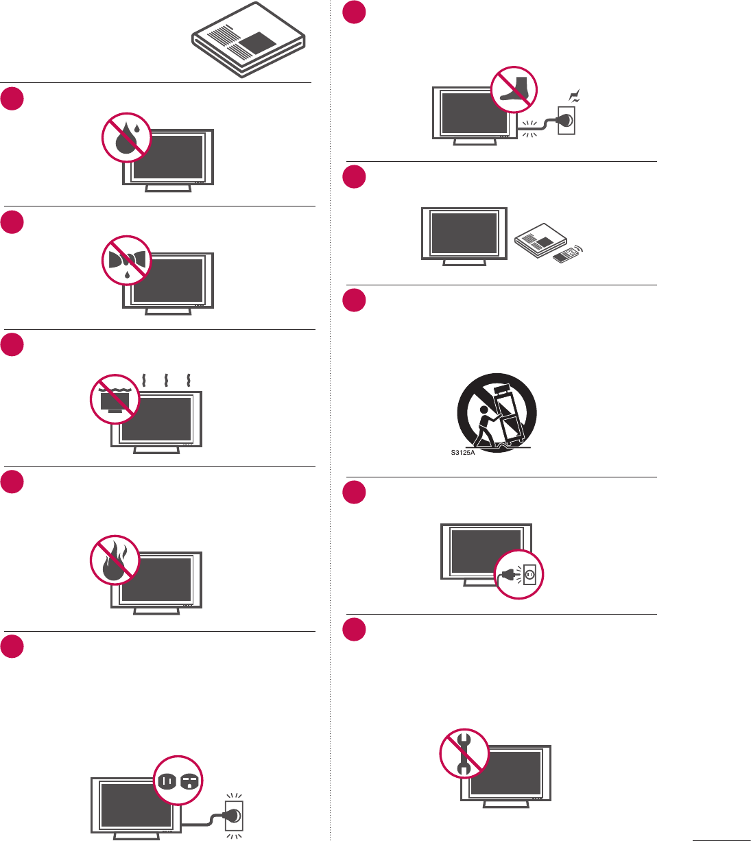
6 Protect the power cord from being walked on or
pinched particularly at plugs, convenience
receptacles, and the point where they exit from
the apparatus.
Antenna Lead in Wire
Antenna Discharge Unit
(NEC Section 810-20)
Grounding Conductor
(NEC Section 810-21)
Ground Clamps
Power Service Grounding
Electrode System (NEC
Art 250, Part H)
Ground Clamp
Electric Service
Equipment
Short-circuit
Breaker
Power
Supply
NEC: National Electrical Code
7 Only use attachments/accessories specified by
the manufacturer.
Antenna Lead in Wire
Antenna Discharge Unit
(NEC Section 810-20)
Grounding Conductor
(NEC Section 810-21)
Ground Clamps
Power Service Grounding
Electrode System (NEC
Art 250, Part H)
Ground Clamp
Electric Service
Equipment
Short-circuit
Breaker
Power
Supply
NEC: National Electrical Code
8 Use only with the cart, stand, tripod, bracket, or
table specified by the manufacturer, or sold with
the apparatus. When a cart is used, use caution
when moving the cart/apparatus combination to
avoid injury from tip-over.
Antenna Lead in Wire
Antenna Discharge Unit
(NEC Section 810-20)
Grounding Conductor
(NEC Section 810-21)
Ground Clamps
Power Service Grounding
Electrode System (NEC
Art 250, Part H)
Ground Clamp
Electric Service
Equipment
Short-circuit
Breaker
Power
Supply
NEC: National Electrical Code
9 Unplug this apparatus during lighting storms or
when unused for long periods of time.
Antenna Lead in Wire
Antenna Discharge Unit
(NEC Section 810-20)
Grounding Conductor
(NEC Section 810-21)
Ground Clamps
Power Service Grounding
Electrode System (NEC
Art 250, Part H)
Ground Clamp
Electric Service
Equipment
Short-circuit
Breaker
Power
Supply
NEC: National Electrical Code
10 Refer all servicing to qualified service personnel.
Servicing is required when the apparatus has
been damaged in any way, such as power-supply
cord or plug is damaged, liquid has been spilled
or objects have fallen into the apparatus, the
apparatus has been exposed to rain or moisture,
does not operate normally, or has been dropped.
Antenna Lead in Wire
Antenna Discharge Unit
(NEC Section 810-20)
Grounding Conductor
(NEC Section 810-21)
Ground Clamps
Power Service Grounding
Electrode System (NEC
Art 250, Part H)
Ground Clamp
Electric Service
Equipment
Short-circuit
Breaker
Power
Supply
NEC: National Electrical Code
SAFETY INSTRUCTIONS
IMPORTANT SAFETY INSTRUCTIONS
Read these instructions.
Keep these instructions.
Heed all warnings.
Follow all instructions.
1 Do not use this apparatus near water.
Antenna Lead in Wire
Antenna Discharge Unit
(NEC Section 810-20)
Grounding Conductor
(NEC Section 810-21)
Ground Clamps
Power Service Grounding
Electrode System (NEC
Art 250, Part H)
Ground Clamp
Electric Service
Equipment
Short-circuit
Breaker
Power
Supply
NEC: National Electrical Code
2 Clean only with a dry cloth.
Antenna Lead in Wire
Antenna Discharge Unit
(NEC Section 810-20)
Grounding Conductor
(NEC Section 810-21)
Ground Clamps
Power Service Grounding
Electrode System (NEC
Art 250, Part H)
Ground Clamp
Electric Service
Equipment
Short-circuit
Breaker
Power
Supply
NEC: National Electrical Code
3 Do not block any ventilation openings. Install in
accordance with the manufacturer’s instructions.
Antenna Lead in Wire
Antenna Discharge Unit
(NEC Section 810-20)
Grounding Conductor
(NEC Section 810-21)
Ground Clamps
Power Service Grounding
Electrode System (NEC
Art 250, Part H)
Ground Clamp
Electric Service
Equipment
Short-circuit
Breaker
Power
Supply
NEC: National Electrical Code
4 Do not install near any heat sources such as
radiators, heat registers, stoves, or other
apparatus (including amplifiers)that produce
heat.
Antenna Lead in Wire
Antenna Discharge Unit
(NEC Section 810-20)
Grounding Conductor
(NEC Section 810-21)
Ground Clamps
Power Service Grounding
Electrode System (NEC
Art 250, Part H)
Ground Clamp
Electric Service
Equipment
Short-circuit
Breaker
Power
Supply
NEC: National Electrical Code
5 Do not defeat the safety purpose of the polar-
ized or grounding-type plug. A polarized plug
has two blades with one wider than the other. A
grounding type plug has two blades and a third
grounding prong, The wide blade or the third
prong are provided for your safety. If the
provided plug does not fit into your outlet,
consult an electrician for replacement of the
obsolete outlet.
Antenna Lead in Wire
Antenna Discharge Unit
(NEC Section 810-20)
Grounding Conductor
(NEC Section 810-21)
Ground Clamps
Power Service Grounding
Electrode System (NEC
Art 250, Part H)
Ground Clamp
Electric Service
Equipment
Short-circuit
Breaker
Power
Supply
NEC: National Electrical Code
Antenna Lead in Wire
Antenna Discharge Unit
(NEC Section 810-20)
Grounding Conductor
(NEC Section 810-21)
Ground Clamps
Power Service Grounding
Electrode System (NEC
Art 250, Part H)
Ground Clamp
Electric Service
Equipment
Short-circuit
Breaker
Power
Supply
NEC: National Electrical Code
4
16 As long as this unit is connected to the AC wall
outlet, it is not disconnected from the AC
power source even if you turn off this unit by
SWITCH.
17 Do not expose to dripping or splashing and do
not place objects filled with liquids, such as
vases, cups, etc. on or over the apparatus (e.g.
on shelves above the unit).
Antenna Lead in Wire
Antenna Discharge Unit
(NEC Section 810-20)
Grounding Conductor
(NEC Section 810-21)
Ground Clamps
Power Service Grounding
Electrode System (NEC
Art 250, Part H)
Ground Clamp
Electric Service
Equipment
Short-circuit
Breaker
Power
Supply
NEC: National Electrical Code
18 GROUNDING
Ensure that you connect the earth ground wire
to prevent possible electric shock. (i.e. a TV
with a three-prong grounded AC plug must be
connected to a three-prong grouned AC
outlet) If grounding methods are not possible,
have a qualified electrician install a separate
circuit breaker.
Do not try to ground the unit by connecting it
to telephone wires, lightening rods, or gas
pipes.
Antenna Lead in Wire
Antenna Discharge Unit
(NEC Section 810-20)
Grounding Conductor
(NEC Section 810-21)
Ground Clamps
Power Service Grounding
Electrode System (NEC
Art 250, Part H)
Ground Clamp
Electric Service
Equipment
Short-circuit
Breaker
Power
Supply
NEC: National Electrical Code
19 DISCONNECTING DEVICE FROM MAINS
Mains plug is the disconnecting device.
The plug must remain readily operable.
20 Dot Defect
The Plasma or LCD panel is a high technology
product with resolution of two million to six
million pixels. In a very few cases, you could see
fine dots on the screen while you’re viewing the
TV. Those dots are deactivated pixels and do
not affect the performance and reliability of
the TV.
21 Generated Sound
“Cracking” noise: A cracking noise that occurs
when watching or turning off the TV is
generated by plastic thermal contraction due
to temperature and humidity. This noise is
common for products where thermal
deformation is required.
Electrical circuit humming/panel buzzing: A low
level noise is generated from a high-speed
switching circuit, which supplies a large amount
of current to operate a product. It varies
depending on the product.
This generated sound does not affect the
performance and reliability of the product.
11 Never touch this apparatus or antenna during
a thunder or lighting storm.
12 When mounting a TV on the wall, make sure
not to install the TV by the hanging power and
signal cables on the back of the TV.
13 Do not allow an impact shock or any objects to
fall into the product, and do not drop onto the
screen with something.
14 CAUTION concerning the Power Cord :
It is recommend that appliances be placed
upon a dedicated circuit; that is, a single outlet
circuit which powers only that appliance and
has no additional outlets or branch circuits.
Check the specification page of this owner's
manual to be certain.
Do not connect too many appliances to the
same AC power outlet as this could result in
fire or electric shock.
Do not overload wall outlets. Overloaded wall
outlets, loose or damaged wall outlets,
extension cords, frayed power cords, or
damaged or cracked wire insulation are
dangerous. Any of these conditions could
result in electric shock or fire. Periodically
examine the cord of your appliance, and if its
appearance indicates damage or deterioration,
unplug it, discontinue use of the appliance, and
have the cord replaced with an exact
replacement part by an authorized servicer.
Protect the power cord from physical or
mechanical abuse, such as being twisted,
kinked, pinched, closed in a door, or walked
upon. Pay particular attention to plugs, wall
outlets, and the point where the cord exits the
appliance.
Do not make the TV with the power cord
plugged in. Do not use a damaged or loose
power cord. Be sure do grasp the plug when
unplugging the power cord. Do not pull on the
power cord to unplug the TV.
Antenna Lead in Wire
Antenna Discharge Unit
(NEC Section 810-20)
Grounding Conductor
(NEC Section 810-21)
Ground Clamps
Power Service Grounding
Electrode System (NEC
Art 250, Part H)
Ground Clamp
Electric Service
Equipment
Short-circuit
Breaker
Power
Supply
NEC: National Electrical Code
15 WARNING - To reduce the risk of fire or
electrical shock, do not expose this product to
rain, moisture or other liquids. Do not touch
the TV with wet hands. Do not install this
product near flammable objects such as
gasoline or candles or expose the TV to direct
air conditioning.
Antenna Lead in Wire
Antenna Discharge Unit
(NEC Section 810-20)
Grounding Conductor
(NEC Section 810-21)
Ground Clamps
Power Service Grounding
Electrode System (NEC
Art 250, Part H)
Ground Clamp
Electric Service
Equipment
Short-circuit
Breaker
Power
Supply
NEC: National Electrical Code
5
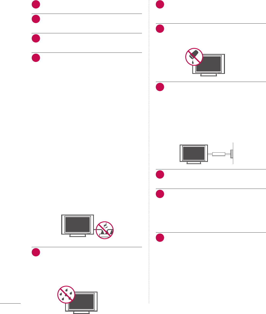
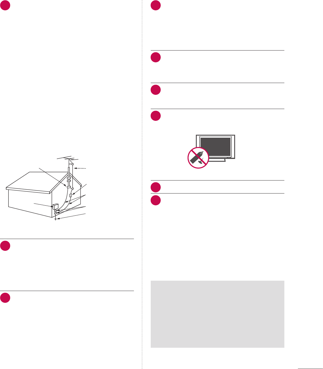
22 ANTENNAS
Outdoor antenna grounding
If an outdoor antenna is installed, follow the
precautions below. An outdoor antenna system
should not be located in the vicinity of
overhead power lines or other electric light or
power circuits, or where it can come in contact
with such power lines or circuits as death or
serious injury can occur.
Be sure the antenna system is grounded so as
to provide some protection against voltage
surges and built-up static charges.
Section 810 of the National Electrical Code
(NEC) in the U.S.A. provides information with
respect to proper grounding of the mast and
supporting structure, grounding of the lead-in
wire to an antenna discharge unit, size of
grounding conductors, location of antenna
discharge unit, connection to grounding
electrodes and requirements for the grounding
electrode.
Antenna grounding according to the
National Electrical Code, ANSI/NFPA 70
Antenna Lead in Wire
Antenna Discharge Unit
(NEC Section 810-20)
Grounding Conductor
(NEC Section 810-21)
Ground Clamps
Power Service Grounding
Electrode System (NEC
Art 250, Part H)
Ground Clamp
Electric Service
Equipment
Short-circuit
Breaker
Power
Supply
NEC: National Electrical Code
23 Cleaning
When cleaning, unplug the power cord and
scrub gently with a soft cloth to prevent
scratching. Do not spray water or other liquids
directly on the TV as electric shock may occur.
Do not clean with chemicals such as alcohol,
thinners or benzene.
24 Moving
Make sure the product is turned off, unplugged
and all cables have been removed. It may take
2 or more people to carry larger TVs. Do not
press against or put stress on the front panel
of the TV.
25 Ventilation
Install your TV where there is proper
ventilation. Do not install in a confined space
such as a bookcase. Do not cover the product
with cloth or other materials (e.g.) plastic while
plugged in. Do not install in excessively dusty
places.
26 Take care not to touch the ventilation
openings. When watching the TV for a long
period, the ventilation openings may become
hot.
27 If you smell smoke or other odors coming from
the TV, unplug the power cord contact and
authorized service center.
28 Do not press strongly upon the panel with a
hand or sharp object such as nail, pencil or pen,
or make a scratch on it.
Antenna Lead in Wire
Antenna Discharge Unit
(NEC Section 810-20)
Grounding Conductor
(NEC Section 810-21)
Ground Clamps
Power Service Grounding
Electrode System (NEC
Art 250, Part H)
Ground Clamp
Electric Service
Equipment
Short-circuit
Breaker
Power
Supply
NEC: National Electrical Code
29 Keep the product away from direct sunlight.
30 For LCD TV
If the TV feels cold to the touch, there may be
a small “flicker” when it is turned on. This is
normal, there is nothing wrong with TV.
Some minute dot defects may be visible on the
screen, appearing as tiny red, green, or blue
spots. However, they have no adverse effect on
the monitor's performance.
Avoid touching the LCD screen or holding your
finger(s) against it for long periods of time.
Doing so may produce some temporary
distortion effects on the screen.
ON DISPOSAL
(Only Hg lamp used LCD TV)
The fluorescent lamp used in this product
contains a small amount of mercury. Do not
dispose of this product with general
household waste. Disposal of this product
must be carried out in accordance to the
regulations of your local authority.

6
CONTENTS
WATCHING TV / CHANNEL CONTROL
Remote Control Functions . . . . . . . . . . . . . . . . 50
Turning On The TV ...................... 52
Channel Selection........................ 53
Volume Adjustment ...................... 53
On-Screen Menus Selection ............... 54
Channel Setup
- Auto Scan (Auto Tuning) ............. 55
- Add / Delete Channel (Manual Tuning) . 56
- Channel Editing ..................... 57
Channel Label ........................... 58
Input List ............................... 59
Example Electronic Program Guide.......... 60
USB
Entry Modes . . . . . . . . . . . . . . . . . . . . . . . . . . . . 61
Photo List .............................. 64
Music List............................... 68
Extra Contents .......................... 70
WARNING / CAUTION ............... 2
SAFETY INSTRUCTIONS ............. 3
FEATURES OF THIS TV ............... 8
PREPARATION
Accessories ............................... 9
Front Panel Information................... 12
Back Panel Information ................... 15
Stand Instructions ....................... 19
Cable Management ...................... 23
Desktop Pedestal Installation .............. 26
Swivel Stand ............................ 26
Attaching the TV to a desk ................ 27
VESA Wall Mounting ..................... 29
Securing the TV to the wall to prevent falling
When the TV is used on a stand ........... 31
Antenna or Cable Connection ............. 32
MPI Card Slot / PPV Card Installation....... 33
EXTERNAL EQUIPMENT SETUP
HD Receiver Setup....................... 34
DVD Setup ............................. 37
VCR Setup ............................. 39
Other A/V Source Setup .................. 41
Audio Out Connection ................... 42
PC Setup ............................... 43

7
PICTURE CONTROL
PIP (Picture-In-Picture) . . . . . . . . . . . . . . . . . . . 71
Picture Size (Aspect Ratio) Control......... 73
Preset Picture Settings (Picture Mode)...... 75
Manual Picture Adjustment - User Mode . . . . 76
Picture Improvement Technology .......... 77
Picture Reset ........................... 79
Demo mode............................. 80
SOUND & LANGUAGE CONTROL
Auto Volume Leveler (Auto Volume) . . . . . . . . 81
Preset Sound Settings (Sound Mode)....... 82
Sound Setting Adjustment - User Mode . . . . . 83
- SRS TruSurround XT ................. 84
- Infinite Sound ....................... 84
Clear Voice ll............................ 86
Balance ................................ 87
TV Speakers On/Off Setup................ 88
Audio Reset ............................ 89
Stereo/SAP Broadcast Setup .............. 90
Audio Language ......................... 91
On-Screen Menus Language Selection . . . . . . 92
Caption Mode
- Analog Broadcasting System Captions . . 93
- Digital Broadcasting System Captions . . 94
- Caption Option ..................... 95
TIME SETTING
Clock Setting
- Auto Clock Setup . . . . . . . . . . . . . . . . . . . 96
- Manual Clock Setup ................. 97
Auto On/Off Time Setting ................ 98
Sleep Timer Setting ...................... 99
Auto Shut-Off Setting ................... 100
PARENTAL CONTROL / RATINGS
Set Password & Lock System . . . . . . . . . . . . . 102
Channel Blocking ....................... 105
Movie & TV Rating...................... 106
Downloadable Rating.................... 111
External Input Blocking .................. 112
APPENDIX
Troubleshooting........................ 113
Maintenance ........................... 115
Product Specifications ................... 116
Programming the Remote Control ......... 120
IR Codes .............................. 123
Open Source License .................... 125
8
FEATURES OF THIS TV
WARNING
RISK OF ELECTRIC SHOCK
DO NOT OPEN
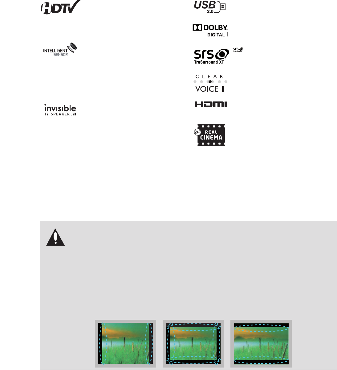
IMPORTANT INFORMATION TO PREVENT
“IMAGE BURN / BURN-IN” ON YOUR TV SCREEN
V When a fixed image (e.g. logos, screen menus, video game, and computer display) is displayed on the TV for
an extended period, it can become permanently imprinted on the screen. This phenomenon is known as
“image burn” or “burn-in.” Image burn is not covered under the manufacturer’s warranty.
V In order to prevent image burn, avoid displaying a fixed image on your TV screen for a prolonged period (2
or more hours for LCD, 1 or more hours for Plasma).
V Image burn can also occur on the letterboxed areas of your TV if you use the 4:3 aspect ratio setting for an
extended period.
V This feature is not available for all models.
High-definition television. High-resolution digital
television broadcast and playback system composed
of roughly a million or more pixels, 16:9 aspect-
ratio screens, and AC3 digital audio. A subset of
digital television, HDTV formats include 1080i and
720p resolutions.
Unlike other sensors which can only sense brightness
of ambient light, LG’s “Intelligent Sensor” uses 4,096
sensing steps to evaluate its surroundings. Using a
sophisticated algorithm, the LG processes picture
quality elements including brightness, contrast,
color, sharpness and white balance. The result is a
picture optimized for it’s surroundings, more pleasing
to watch and which can also save up to 50% in power
consumption.
LG TV include a unique invisible speaker system,
tuned by renowned audio expert, Mr. Mark Levinson.
Speakers are embedded in strategic spots behind the
front cabinet and use minute vibrations to turn the
entire front bezel into the speaker system. The result
is a clean, polished look, and enhanced audio by
increasing the “sweet spot”, giving a wider and richer
sound field.
View videos and photos and listen to music on your
TV through USB 2.0 (‘videos’ dependent on model).
Manufactured under license from Dolby Laboratories.
“Dolby “and the double-D symbol are trademarks of
Dolby Laboratories.
is a trademark of SRS Labs, Inc.
TruSurround XT technology is incorporated under
license from SRS Labs, Inc.
Automatically enhances and amplifies the sound of
human voice frequency range to help keep dialogue
audible when background noise swells.
HDMI, the HDMI logo and High-Definition Multimedia
Interface are trademarks or registered trademarks of
HDMI Licensing LLC."
Matches the original frame rate of the film for a more
film-like experience
PREPARATION
9
For 32/37/42LG710H
PREPARATION
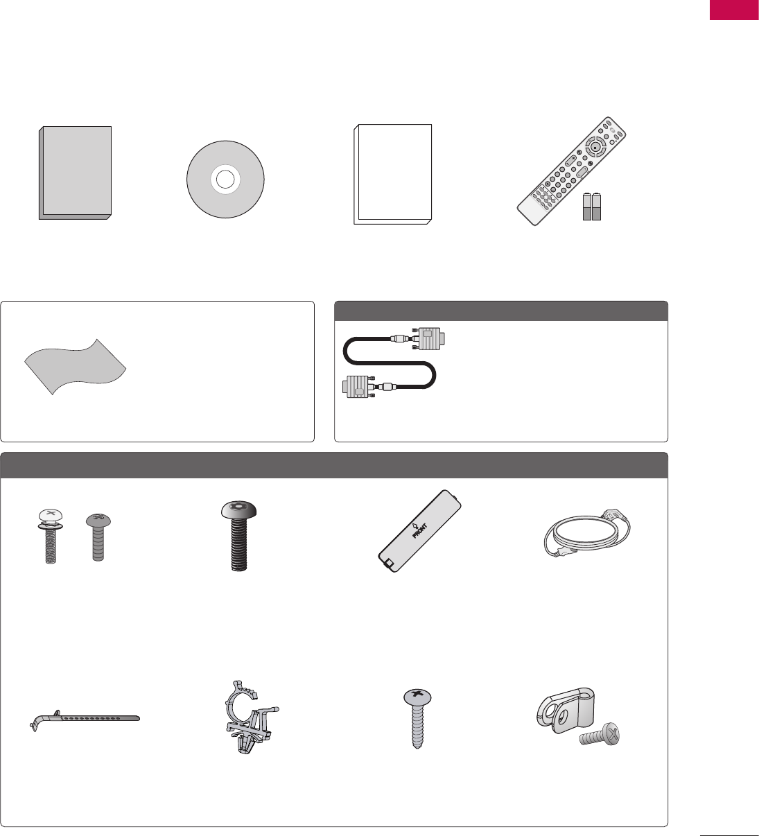
Ensure that the following accessories are included with your TV. If an accessory is missing, please contact the
dealer where you purchased the TV.
The accessories included may differ from the images below.
Not included with all models.
MUTE
RETURN
CC
TV
POWER
GUIDE
PORTAL
ENTER
VOL CH
1 2 3
4 5 6
78
0
9
FLASHBK
VCR
DVD
INPUT
MENU
INFO
i
STB
P
A
G
E
PIP SAP
PIP CH- PIP CH+
PIP SWAP
PIP INPUT
ALPHA/NUM
REMOVE
RATIO
TIMER
ABC DEF
GHI
WXYZ
TUV
PQRS
MNO
JKL
&@
.:/,
1.5V 1.5V
1.5V 1.5V
1,5Vcc 1,5Vcc
기준점
* Wipe spots on the exterior
only with the polishing cloth.
* Do not wipe roughly when
removing stains. Excessive
pressure may cause
scratches or discoloration.
Polishing Cloth
MUTE
RETURN
CC
TV
POWER
GUIDE
PORTAL
ENTER
VOL CH
1 2 3
4 5 6
78
0
9
FLASHBK
VCR
DVD
INPUT
MENU
INFO
i
STB
P
A
G
E
PIP SAP
PIP CH- PIP CH+
PIP SWAP
PIP INPUT
ALPHA/NUM
REMOVE
RATIO
TIMER
ABC DEF
GHI
WXYZ
TUV
PQRS
MNO
JKL
&@
.:/,
1.5V 1.5V
1.5V 1.5V
1,5Vcc 1,5Vcc
기준점
When using the VGA (D-sub 15-pin
signal cable) PC connection, the user
must use shielded signal interface
cables with ferrite cores to maintain
standards compliance.
D-sub 15-pin
signal cable
Optional Extras
ACCESSORIES
(For 32/37/42LG710H,
32/37/42/47/55LD650H,
32/37/42LD655H)
(For 32/37/42LD660H,
32/37/42LD665H
32/37/42/47/55LV555H)
MUTE
RETURN
CC
TV
POWER
GUIDE
PORTAL
ENTER
VOL CH
1 2 3
4 5 6
78
0
9
FLASHBK
VCR
DVD
INPUT
MENU
INFO
i
STB
P
A
G
E
PIP SAP
PIP CH- PIP CH+
PIP SWAP
PIP INPUT
ALPHA/NUM
REMOVE
RATIO
TIMER
ABC DEF
GHI
WXYZ
TUV
PQRS
MNO
JKL
&@
.:/,
1.5V 1.5V
1.5V 1.5V
1,5Vcc 1,5Vcc
기준점
MUTE
RETURN
CC
TV
POWER
GUIDE
PORTAL
ENTER
VOL CH
1 2 3
4 5 6
78
0
9
FLASHBK
VCR
DVD
INPUT
MENU
INFO
i
STB
P
A
G
E
PIP SAP
PIP CH- PIP CH+
PIP SWAP
PIP INPUT
ALPHA/NUM
REMOVE
RATIO
TIMER
ABC DEF
GHI
WXYZ
TUV
PQRS
MNO
JKL
&@
.:/,
1.5V 1.5V
1.5V 1.5V
1,5Vcc 1,5Vcc
기준점
MUTE
RETURN
CC
TV
POWER
GUIDE
PORTAL
ENTER
VOL CH
1 2 3
4 5 6
78
0
9
FLASHBK
VCR
DVD
INPUT
MENU
INFO
i
STB
P
A
G
E
PIP SAP
PIP CH- PIP CH+
PIP SWAP
PIP INPUT
ALPHA/NUM
REMOVE
RATIO
TIMER
ABC DEF
GHI
WXYZ
TUV
PQRS
MNO
JKL
&@
.:/,
1.5V 1.5V
1.5V 1.5V
1,5Vcc 1,5Vcc
기준점
MUTE
RETURN
CC
TV
POWER
GUIDE
PORTAL
ENTER
VOL CH
1 2 3
4 5 6
78
0
9
FLASHBK
VCR
DVD
INPUT
MENU
INFO
i
STB
P
A
G
E
PIP SAP
PIP CH- PIP CH+
PIP SWAP
PIP INPUT
ALPHA/NUM
REMOVE
RATIO
TIMER
ABC DEF
GHI
WXYZ
TUV
PQRS
MNO
JKL
&@
.:/,
1.5V 1.5V
1.5V 1.5V
1,5Vcc 1,5Vcc
기준점
Owner’s Manual CD Manual Quick Reference Guide Remote control,
batteries (AAA)
x 4 x 4 x 2
Screws for
stand assembly
(Refer to P.19)
Torx plus
Star-head screw
(Refer to P.19)
Protection cover
(Refer to P.19) Power cord
(For 32LG710H)
Cable holder
(Refer to P.23)
Plug-in type holder
(Refer to P.23)
Screw for stand fixing
(Refer to P.27)
Protective bracket and
screw for power cord
(Refer to P.23)
PREPARATION
10
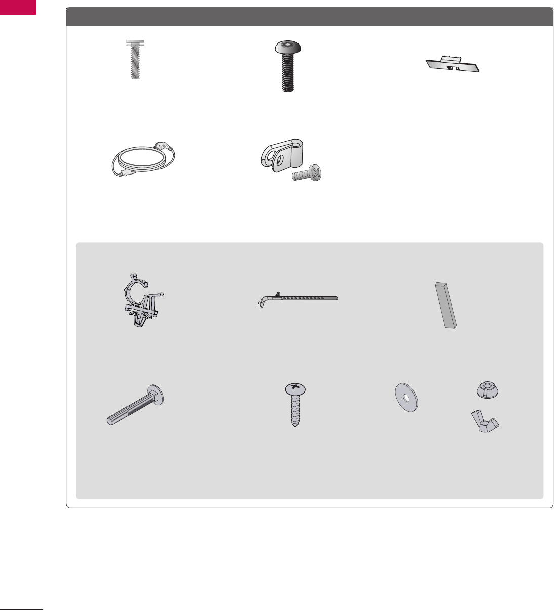
PREPARATION
For 32/37/42/47/55LD650H, 32/37/42LD655H, 32/37/42LD660H, 32/37/42LD665H
x 8
(M4 x 20) x 2
Screws for
stand assembly
(Refer to P.20)
Torx plus
Star-head screw
(Refer to P.20)
Protection Cover
(Refer to P.20)
Power cord
Protective bracket and
screw for power cord
(Refer to P.24)
(For 32/37/42LD650H, 32/37/42LD655H, 32/37/42LD660H, 32/37/42LD665H)
x 4
Plug-in type holder
(Refer to P.24)
Cable holder
(Refer to P.24)
Rubbers for
stand fixing
(Refer to P.27)
x 2
x2
x2
x2
Screws for
stand fixing
(Refer to P.27)
Screw for
stand fixing
(Refer to P.27)
Washers for
stand fixing
(Refer to P.27)
Nuts for
stand fixing
(Refer to P.27)
PREPARATION
11
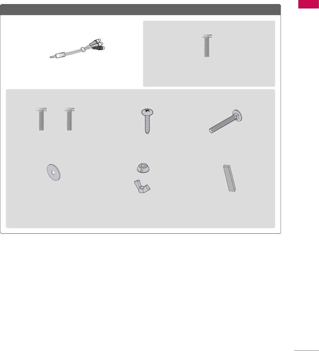
For 32/37/42/47/55LV555H
(For 47/55LV555H)
x 8
(M4 x 12)
Composite gender cable Screws for stand assembly
(Refer to P.22)
(For 32/37/42LV555H)
x 4 x 4
(M4 x 14) (M4 x 20) x 2
Screws for
stand assembly
(Refer to P.21)
Screw for
stand fixing
(Refer to P.27)
Screws for
stand fixing
(Refer to P.27)
x 2
x 2
x 2
Washers for
stand fixing
(Refer to P.27)
Nuts for
stand fixing
(Refer to P.27)
Rubbers for
stand fixing
(Refer to P.27)
PREPARATION
12
PREPARATION
CH
VOL
MENU
INPUT
ENTER
CH
VOL
MENU
INPUT
ENTER
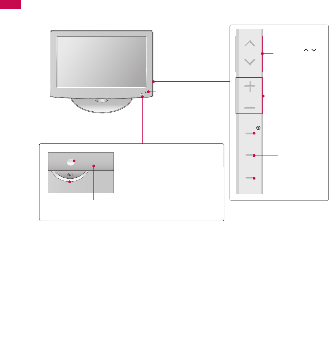
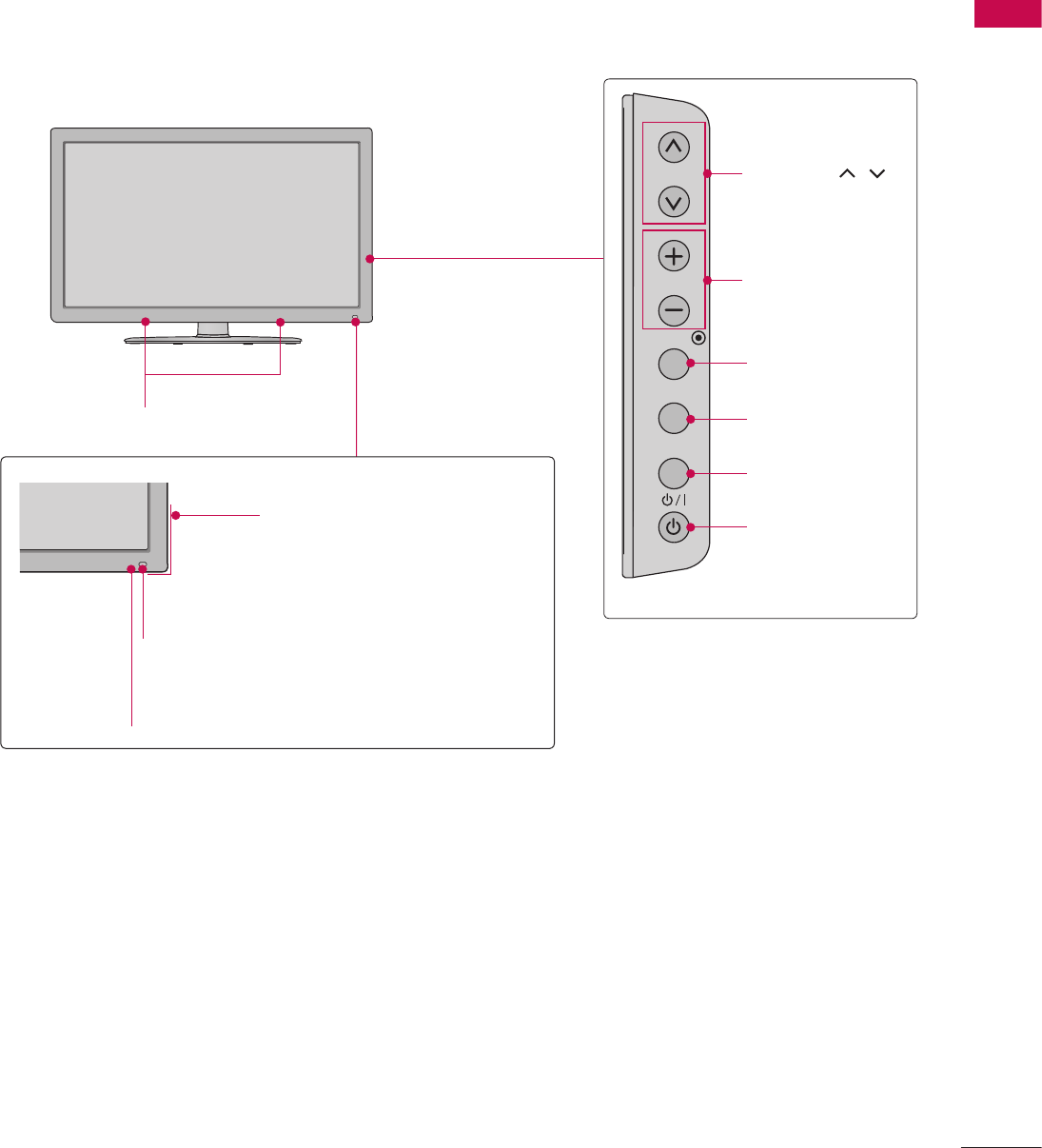
POWER Button
Power/Standby Indicator
Illuminates red in standby mode.
Illuminates blue when the set is
switched on.
CH
VOL
MENU
INPUT
ENTER
VOLUME (+, -)
Buttons
ENTER Button
MENU Button
INPUT Button
Remote Control Sensor
CHANNEL(
ὤ㨴㥄
,
ὤ㨴㥄
)
Buttons
Intelligent Sensor
Adjusts picture according
to the surrounding
conditions.
32/37/42LG710H
FRONT PANEL INFORMATION
V Image shown may differ from your TV.
PREPARATION
13
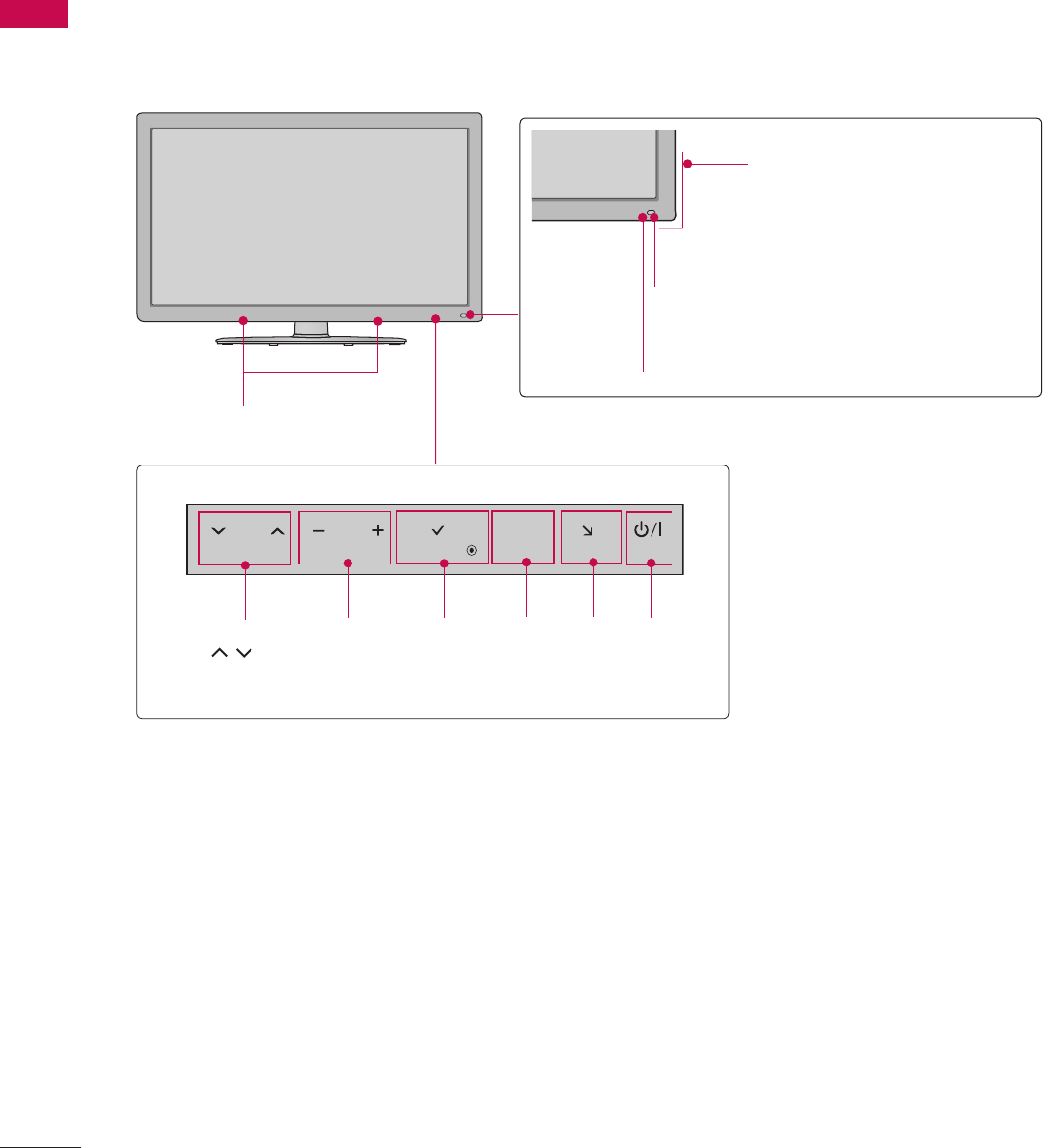
32/37/42/47/55LD650H, 32/37/42LD655H, 32/37/42LD660H, 32/37/42LD665H
CH
VOL
ENTER
INPUT
MENU
VOLUME (+, -)
Buttons
ENTER Button
MENU Button
INPUT Button
POWER Button
CHANNEL(
ὤ㨴㥄
,
ὤ㨴㥄
)
Buttons
CH
VOL
ENTER
INPUT
MENU
Intelligent Sensor
Adjusts picture according to
the surrounding conditions.
Power/Standby Indicator
Illuminates red in standby mode.
Illuminates blue when the set is
switched on.
Remote Control Sensor
CH
VOL
ENTER
INPUT
MENU
SPEAKER
PREPARATION
14
PREPARATION
Intelligent Sensor
Adjusts picture according to
the surrounding conditions.
Power/Standby Indicator
Illuminates red in standby mode.
Illuminates blue when the set is
switched on.
Remote Control Sensor
ENTER
CH VOL HOME
H
INPUT
ENTER
CH VOL HOME
H
INPUT
ENTER
CH VOL HOME
H
INPUT
CHANNEL
(
ὤ㨴㥄
,
ὤ㨴㥄
)
Buttons
VOLUME
(+, -)
Buttons
ENTER
Button
MENU
Button
INPUT
Button
POWER
Button
SPEAKER
32/37/42/47/55LV555H
PREPARATION
15
ANTENNA IN M.P.I.
AV IN 2
L/MONO
R
AUDIO
VIDEO
USB IN
REMOTE
CONTROL OUT
OPTICAL
DIGITAL
AUDIO OUT
AV IN 1
AUDIO VIDEO
MONO
/
UPDATE
RESET
LAN
(SERVICE ONLY)
COMPONENT IN
VIDEO AUDIO
HDMI/DVI IN
2
1(DVI)
RJP
INTERFACE
SPEAKER OUT
8
RGB(PC) AUDIO
(RGB/DVI)
RGB IN
RS-232C IN
(SERVICE ONLY)
TV-LINK
CFG
GAME
CONTROL
.1
.2.3.4.5.6.7.8
.9
11
16
10
111213
15
14 .6
ANTENNA IN M.P.I.
AV IN 2
L/MONO
R
AUDIO
VIDEO
USB IN
REMOTE
CONTROL
OUT
OPTICAL
DIGITAL
UPDATE
RESET
LAN
2
1
RJP
INTERFACE
SPEAKER
OUT
8
AUDIO IN
(RGB/DVI)
RGB IN (PC)
TV-LINK CFG
GAME
CONTROL
RS-232C IN
(SERVIER ONLY)
AUDIO OUT
AV IN 1
AUDIO
VIDEO
MONO
/
COMPONENT
IN
L
R
HDMI/DVI IN
AC IN
ANTENNA IN
OPTICAL
DIGITAL
UPDATERESET
LAN
SPEAKER
OUT
8
TV-LINK CFG
GAME CONTROL
/ M.P.I.
AUDIO OUT
AUDIO
VIDEO
HDMI/DVI IN
2
1
AV IN 1
MONO
/
COMPONENT
IN
L
R
REMOTE
CONTROL
OUT
RJP
INTERFACE
AUDIO IN
(RGB/DVI)
RGB IN (PC) RS-232C IN
(SERVIER ONLY)
ANTENNA IN
AV IN 2
L/MONO
R
AUDIO
VIDEO
USB IN
AC IN
SERVICE
ONLY
OPTICAL
DIGITAL
UPDATE
RESET
LAN2
1
HDMI/DVI IN
2
1
RJP
INTERFACE
SPEAKER
OUT
8
RGB IN (PC) AUDIO IN
(RGB/DVI)
TV-LINK CFG
GAME
CONTROL/MPI
RS-232C IN
(SERVICE ONLY)
AUDIO OUT
AV IN 1
AUDIO
VIDEO MONO
/
COMPONENT
IN
L
R
LAN
ANTENNA IN
AV IN 2
L/MONO
R
AUDIO
VIDEO
USB IN
AC IN
SERVICE
ONLY
OPTICAL
DIGITAL
UPDATE
RESET
LAN2
1
HDMI/DVI IN
2
1
RJP
INTERFACE
SPEAKER
OUT
8
RGB IN (PC) AUDIO IN
(RGB/DVI)
TV-LINK CFG
GAME
CONTROL/MPI
RS-232C IN
(SERVICE ONLY)
AUDIO OUT
AV IN 1
AUDIO
VIDEO MONO
/
COMPONENT
IN
L
R
LAN
.9
18
14
.1
.5.4.8.61717
15
13 .7 12
ANTENNA IN M.P.I.
AV IN 2
L/MONO
R
AUDIO
VIDEO
USB IN
REMOTE
CONTROL
OUT
OPTICAL
DIGITAL
UPDATE
RESET
LAN
2
1
RJP
INTERFACE
SPEAKER
OUT
8
AUDIO IN
(RGB/DVI)
RGB IN (PC)
TV-LINK CFG
GAME
CONTROL
RS-232C IN
(SERVIER ONLY)
AUDIO OUT
AV IN 1
AUDIO
VIDEO
MONO
/
COMPONENT
IN
L
R
HDMI/DVI IN
AC IN
ANTENNA IN
OPTICAL
DIGITAL
UPDATERESET
LAN
SPEAKER
OUT
8
TV-LINK CFG
GAME CONTROL
/ M.P.I.
AUDIO OUT
AUDIO
VIDEO
HDMI/DVI IN
2
1
AV IN 1
MONO
/
COMPONENT
IN
L
R
REMOTE
CONTROL
OUT
RJP
INTERFACE
AUDIO IN
(RGB/DVI)
RGB IN (PC) RS-232C IN
(SERVIER ONLY)
16
11
.2
11
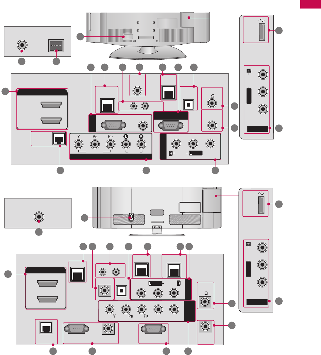
BACK PANEL INFORMATION
V Image shown may differ from your TV.
32/37/42LG710H
32/37/42LD660H, 32/37/42LD665H
PREPARATION
16
PREPARATION
ANTENNA IN M.P.I.
AV IN 2
L/MONO
R
AUDIO
VIDEO
USB IN
REMOTE
CONTROL
OUT
OPTICAL
DIGITAL
UPDATE
RESET
LAN
2
1
RJP
INTERFACE
SPEAKER
OUT
8
AUDIO IN
(RGB/DVI)
RGB IN (PC)
TV-LINK CFG
GAME
CONTROL
RS-232C IN
(SERVIER ONLY)
AUDIO OUT
AV IN 1
AUDIO
VIDEO
MONO
/
COMPONENT
IN
L
R
HDMI/DVI IN
AC IN
ANTENNA IN
OPTICAL
DIGITAL
UPDATERESET
LAN
SPEAKER
OUT
8
TV-LINK CFG
GAME CONTROL
/ M.P.I.
AUDIO OUT
AUDIO
VIDEO
HDMI/DVI IN
2
1
AV IN 1
MONO
/
COMPONENT
IN
L
R
REMOTE
CONTROL
OUT
RJP
INTERFACE
AUDIO IN
(RGB/DVI)
RGB IN (PC) RS-232C IN
(SERVIER ONLY)
.6
.1
.2.7
.3.5.4.8 14
15
11
.9
11
16
10
1213
ANTENNA IN M.P.I.
AV IN 2
L/MONO
R
AUDIO
VIDEO
USB IN
REMOTE
CONTROL
OUT
OPTICAL
DIGITAL
UPDATE
RESET
LAN
2
1
RJP
INTERFACE
SPEAKER
OUT
8
AUDIO IN
(RGB/DVI)
RGB IN (PC)
TV-LINK CFG
GAME
CONTROL
RS-232C IN
(SERVIER ONLY)
AUDIO OUT
AV IN 1
AUDIO
VIDEO
MONO
/
COMPONENT
IN
L
R
HDMI/DVI IN
AC IN
ANTENNA IN
OPTICAL
DIGITAL
UPDATERESET
LAN
SPEAKER
OUT
8
TV-LINK CFG
GAME CONTROL
/ M.P.I.
AUDIO OUT
AUDIO
VIDEO
HDMI/DVI IN
2
1
AV IN 1
MONO
/
COMPONENT
IN
L
R
REMOTE
CONTROL
OUT
RJP
INTERFACE
AUDIO IN
(RGB/DVI)
RGB IN (PC) RS-232C IN
(SERVIER ONLY)
.9
10
14
.1
.3.5.4.8.6 11
.6
15
13 .2.7 12
ANTENNA IN M.P.I.
AV IN 2
L/MONO
R
AUDIO
VIDEO
USB IN
REMOTE
CONTROL
OUT
OPTICAL
DIGITAL
UPDATE
RESET
LAN
2
1
RJP
INTERFACE
SPEAKER
OUT
8
AUDIO IN
(RGB/DVI)
RGB IN (PC)
TV-LINK CFG
GAME
CONTROL
RS-232C IN
(SERVIER ONLY)
AUDIO OUT
AV IN 1
AUDIO
VIDEO
MONO
/
COMPONENT
IN
L
R
HDMI/DVI IN
AC IN
ANTENNA IN
OPTICAL
DIGITAL
UPDATERESET
LAN
SPEAKER
OUT
8
TV-LINK CFG
GAME CONTROL
/ M.P.I.
AUDIO OUT
AUDIO
VIDEO
HDMI/DVI IN
2
1
AV IN 1
MONO
/
COMPONENT
IN
L
R
REMOTE
CONTROL
OUT
RJP
INTERFACE
AUDIO IN
(RGB/DVI)
RGB IN (PC) RS-232C IN
(SERVIER ONLY)
16
11
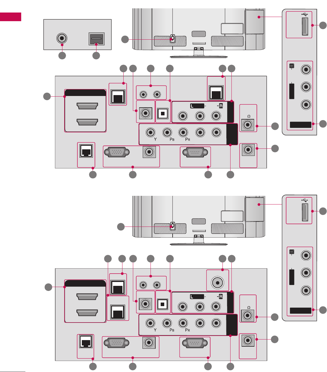
32/37/42LD650H, 32/37/42LD655H
47/55LD650H

PREPARATION
17
USB IN
AV IN 2
VIDEO / AUDIO
USB IN
HDMI/DVI
IN 2
SERVICE
ONLY
1
AUDIO
VIDEO
MONO
/
LR
ANTENNA IN
OPTICAL
DIGITAL
UPDATE
RESET
INTERFACE
RJP
SPEAKER
OUT 8 ( )
AUDIO IN
(RGB/DVI)
RGB IN (PC)
TV-LINK CFG
GAME CONTROL
/ MPI
RS-232C IN
(SERVIER ONLY)
AUDIO OUT
AV IN 1
COMPONENT
IN
HDMI/DVI IN
LAN 1
LAN 2
USB IN
AV IN 2
VIDEO / AUDIO
USB IN
HDMI/DVI
IN 2
SERVICE
ONLY
1
AUDIO
VIDEO
MONO
/
LR
ANTENNA IN
OPTICAL
DIGITAL
UPDATE
RESET
INTERFACE
RJP
SPEAKER
OUT 8 ( )
AUDIO IN
(RGB/DVI)
RGB IN (PC)
TV-LINK CFG
GAME CONTROL
/ MPI
RS-232C IN
(SERVIER ONLY)
AUDIO OUT
AV IN 1 COMPONENT
IN
HDMI/DVI IN
LAN 1
LAN 2
USB IN
AV IN 2
VIDEO / AUDIO
USB IN
HDMI/DVI
IN 2
SERVICE
ONLY
1
AUDIO
VIDEO
MONO
/
LR
ANTENNA IN
OPTICAL
DIGITAL
UPDATE
RESET
INTERFACE
RJP
SPEAKER
OUT 8 ( )
AUDIO IN
(RGB/DVI)
RGB IN (PC)
TV-LINK CFG
GAME CONTROL
/ MPI
RS-232C IN
(SERVIER ONLY)
AUDIO OUT
AV IN 1
COMPONENT
IN
HDMI/DVI IN
LAN 1
LAN 2
.2.713
11 14
12
17 18.1.5.4.6.9.8
.1
11
16
15
32/37/42/47/55LV555H

PREPARATION
18
PREPARATION
.9 SPEAKER OUT (8Ω)
For use with external speakers.
10 REMOTE CONTROL OUT
IR output for controlling an auxiliary device.
11 AV (Audio/Video) IN 1/2
Analog composite connection. Supports standard
definition video only (480i).
12 COMPONENT IN
Analog Connection. Supports HD.
Uses a red, green, and blue cable for video & a
red and white cable for audio.
13 RJP INTERFACE (REMOTE JACK PACK PORT)
Connect this to an LG remote jack pack system.
14 ANTENNA IN
Connect an antenna to receive over-the-air (OTA)
signals.
15 Power Cord Socket
AC power input.
Caution: Never attempt to operate the TV on DC
power.
16 USB IN
Used for viewing multimedia files.
17 LAN
For connecting to a control network.
18 SERVICE ONLY
Used for software updates.
.1 HDMI/DVI IN
Digital Connection.
Supports HD video and Digital audio.
Accepts DVI video using an adapter or HDMI to
DVI cable (not included).
.2 RGB IN (PC)
Analog PC Connection. Uses a D-sub 15 pin
cable (VGA cable).
AUDIO IN (RGB/DVI)
1/8" (0.32 cm) headphone jack for analog PC
audio input.
.3 LAN (SERVICE ONLY)
For connecting to a control network.
.4 RESET
Performs a hardware reset.
UPDATE
Enables/disables software downloads and debug
mode.
.5 TV - LINK CFG
Computer input for programming Free To Guest
services.
.6 GAME CONTROL
Input port for third party game Controllers.
M. P. I.
Allows VOD/PPV devices or set-top boxes to
control the TV.
.7 RS-232C IN (SERVICE ONLY)
Used for software updates.
.8 OPTICAL DIGITAL AUDIO OUT
Optical digital audio output for use with amps
and home theater systems.
Note: In standby mode, this port doesn’t work.
PREPARATION
19
STAND INSTRUCTIONS
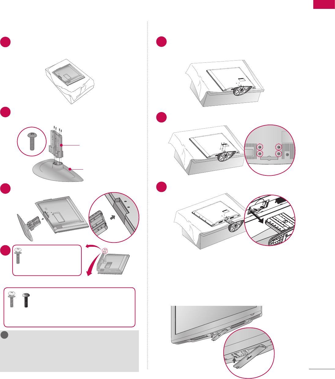
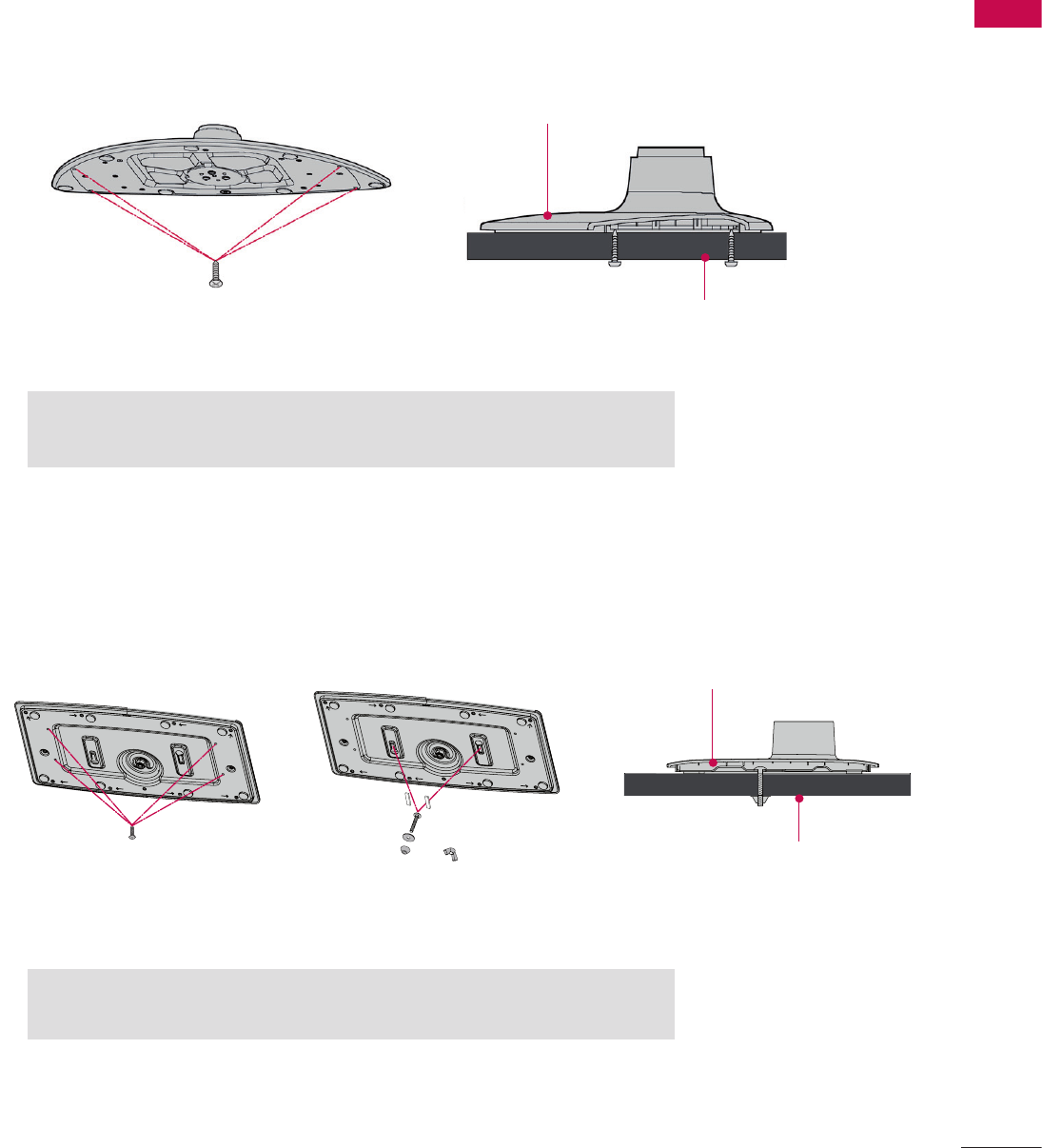
INSTALLATION
1 Carefully place the TV screen side down on a
cushioned surface to protect the screen from
damage.
ὤ㨴㥄
wyv{lj{pvuGjv}ly
2 Assemble the parts of the STAND BODY with
the STAND BASE of the TV.
ὤ㨴㥄
wyv{lj{pvuGjv}ly
STAND BODY
STAND BASE
ὤ㨴㥄
wyv{lj{pvuGjv}ly
3 Insert the stand as shown.
ὤ㨴㥄
wyv{lj{pvuGjv}ly
ὤ㨴㥄
wyv{lj{pvuGjv}ly
4
ὤ㨴㥄
wyv{lj{pvuGjv}ly
x 4 Tighten the stand
with the four screws
(provided as parts of the TV).
ὤ㨴㥄
wyv{lj{pvuGjv}ly
or
ὤ㨴㥄
wyv{lj{pvuGjv}ly
x 2
ὤ㨴㥄
wyv{lj{pvuGjv}ly
x 2
Tighten the two of these four screws and
the two Torx plus star head screws
(provided as parts of the TV) to secure the
TV. Tighten the two Torx plus star head screws with a star
head driver bit (not provided as parts of the TV).
NOTE
G When assembling the desk type stand, make sure
the screws are fully tightened (If not tightened
fully, the TV can tilt forward after the protuct
installation). Do not over tighten.
!
?
!
?
! !
DETACHMENT
1 Carefully place the TV screen side down on a
cushioned surface to protect the screen from
damage.
ὤ㨴㥄
wyv{lj{pvuGjv}ly
2 Remove the four screws that hold the base on.
ὤ㨴㥄
wyv{lj{pvuGjv}ly
ὤ㨴㥄
wyv{lj{pvuGjv}ly
3 Detach the stand from the TV.
ὤ㨴㥄
wyv{lj{pvuGjv}ly
ὤ㨴㥄
wyv{lj{pvuGjv}ly
PROTECTION COVER
After removing the stand, install the included
PROTECTION COVER over the hole for the stand.
Press the PROTECTION COVER into the TV until
you hear it click.
ὤ㨴㥄
wyv{lj{pvuGjv}ly
ὤ㨴㥄
wyv{lj{pvuGjv}ly
V Image shown may differ from your TV.
32/37/42LG710H
PREPARATION
20
PREPARATION
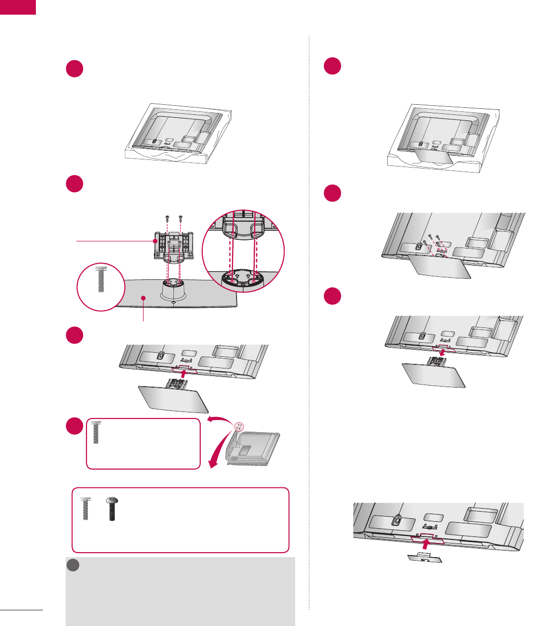
INSTALLATION
1 Carefully place the TV screen side down on a
cushioned surface to protect the screen from
damage.
ὤ㨴㥄
wyv{lj{pvuGjv}ly
AC IN
CABLE MANAGEMEN
T
AC IN
CABLE MANAGEMENT
AC IN
CABLE MANAGEMENT
AC IN
CABLE MANAGEMENT
AC IN
CABLE MANAGEMEN
T
2 Assemble the parts of the STAND BODY with
the STAND BASE of the TV.
ὤ㨴㥄
wyv{lj{pvuGjv}ly
AC IN
CABLE MANAGEMEN
T
AC IN
CABLE MANAGEMENT
AC IN
CABLE MANAGEMENT
AC IN
CABLE MANAGEMENT
AC IN
CABLE MANAGEMEN
T
STAND BODY
STAND BASE
ὤ㨴㥄
wyv{lj{pvuGjv}ly
AC IN
CABLE MANAGEMEN
T
AC IN
CABLE MANAGEMENT
AC IN
CABLE MANAGEMENT
AC IN
CABLE MANAGEMENT
AC IN
CABLE MANAGEMEN
T
ὤ㨴㥄
wyv{lj{pvuGjv}ly
AC IN
CABLE MANAGEMEN
T
AC IN
CABLE MANAGEMENT
AC IN
CABLE MANAGEMENT
AC IN
CABLE MANAGEMENT
AC IN
CABLE MANAGEMEN
T
M4 x 20
3 Insert the stand as shown.
ὤ㨴㥄
wyv{lj{pvuGjv}ly
AC IN
CABLE MANAGEMEN
T
AC IN
CABLE MANAGEMENT
AC IN
CABLE MANAGEMENT
AC IN
CABLE MANAGEMENT
AC IN
CABLE MANAGEMEN
T
4
ὤ㨴㥄
wyv{lj{pvuGjv}ly
AC IN
CABLE MANAGEMEN
T
AC IN
CABLE MANAGEMENT
AC IN
CABLE MANAGEMENT
AC IN
CABLE MANAGEMENT
AC IN
CABLE MANAGEMEN
T
x 4 Tighten the stand
with the four screws
(provided as parts of the TV).
ὤ㨴㥄
wyv{lj{pvuGjv}ly
or
ὤ㨴㥄
wyv{lj{pvuGjv}ly
AC IN
CABLE MANAGEMEN
T
AC IN
CABLE MANAGEMENT
AC IN
CABLE MANAGEMENT
AC IN
CABLE MANAGEMENT
AC IN
CABLE MANAGEMEN
T
x 2
ὤ㨴㥄
wyv{lj{pvuGjv}ly
x 2
Tighten the two of these four screws and
the two Torx plus star head screws
(provided as parts of the TV) to secure the
TV. Tighten the two Torx plus star head screws with a star
head driver bit (not provided as parts of the TV).
NOTE
G When assembling the desk type stand, make sure
the screws are fully tightened (If not tightened
fully, the TV can tilt forward after the protuct
installation). Do not over tighten.
!
?
!
?
! !
DETACHMENT
1 Carefully place the TV screen side down on a
cushioned surface to protect the screen from
damage.
ὤ㨴㥄
wyv{lj{pvuGjv}ly
AC IN
CABLE MANAGEMENT
AC IN
CABLE MANAGEMENT
AC IN
CABLE MANAGEMENT
AC IN
CABLE MANAGEMENT
AC IN
CABLE MANAGEMEN
T
2 Remove the four screws that hold the base on.
ὤ㨴㥄
wyv{lj{pvuGjv}ly
AC IN
CABLE MANAGEMEN
T
AC IN
CABLE MANAGEMENT
AC IN
CABLE MANAGEMENT
AC IN
CABLE MANAGEMENT
AC IN
CABLE MANAGEMEN
T
3 Detach the stand from the TV.
ὤ㨴㥄
wyv{lj{pvuGjv}ly
AC IN
CABLE MANAGEMEN
T
AC IN
CABLE MANAGEMENT
AC IN
CABLE MANAGEMENT
AC IN
CABLE MANAGEMENT
AC IN
CABLE MANAGEMEN
T
PROTECTION COVER
After removing the stand, install the included
PROTECTION COVER over the hole for the stand.
Press the PROTECTION COVER into the TV until
you hear it click.
ὤ㨴㥄
wyv{lj{pvuGjv}ly
AC IN
CABLE MANAGEMEN
T
AC IN
CABLE MANAGEMENT
AC IN
CABLE MANAGEMENT
AC IN
CABLE MANAGEMENT
AC IN
CABLE MANAGEMEN
T
32/37/42/47/55LD650H, 32/37/42LD655H, 32/37/42LD660H, 32/37/42LD665H
PREPARATION
21
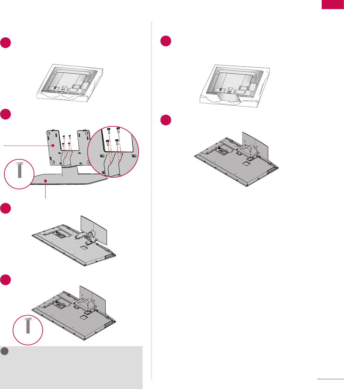
INSTALLATION
1 Carefully place the TV screen side down on a
cushioned surface to protect the screen from
damage.
ὤ㨴㥄
wyv{lj{pvuGjv}ly
AC IN
CABLE MANAGEMEN
T
AC IN
CABLE MANAGEMENT
AC IN
CABLE MANAGEMENT
AC IN
CABLE MANAGEMENT
AC IN
CABLE MANAGEMEN
T
2 Assemble the parts of the STAND BODY with
the STAND BASE of the TV.
ὤ㨴㥄
AC IN
CABLE MANAGEMENT
AC IN
CABLE MANAGEMENT
STAND BODY
STAND BASE
ὤ㨴㥄
AC IN
CABLE MANAGEMENT
AC IN
CABLE MANAGEMENT
ὤ㨴㥄
AC IN
CABLE MANAGEMENT
AC IN
CABLE MANAGEMENT
M4 x 20
3 Insert the stand as shown.
ὤ㨴㥄
AC IN
CABLE MANAGEMENT
AC IN
CABLE MANAGEMENT
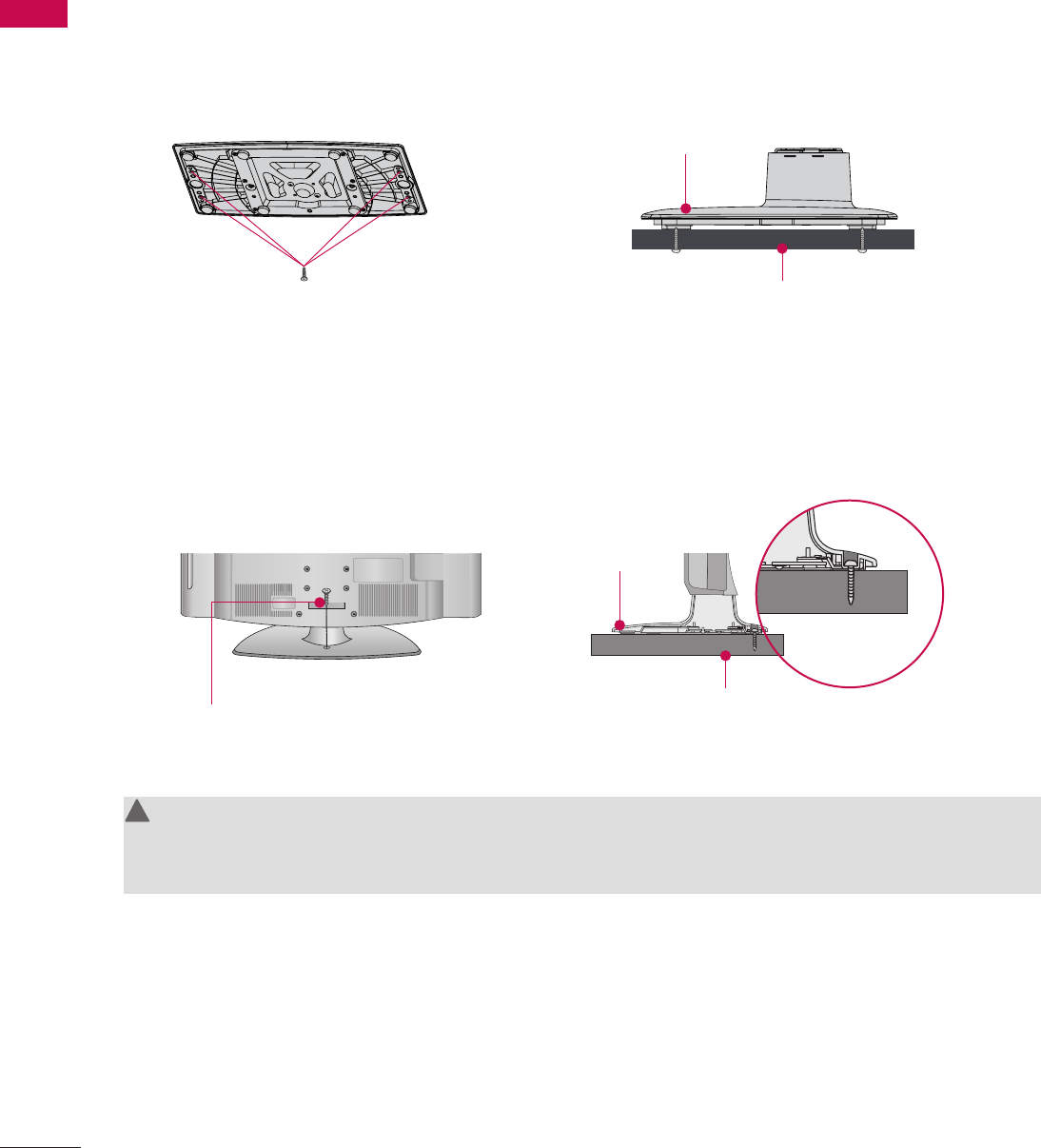
4 Install the 4 screws into the holes shown.
ὤ㨴㥄
AC IN
CABLE MANAGEMENT
AC IN
CABLE MANAGEMENT
ὤ㨴㥄
AC IN
CABLE MANAGEMENT
AC IN
CABLE MANAGEMENT
M4 x 14
NOTE
G When assembling the desk type stand, make sure
the screws are fully tightened (If not tightened
fully, the TV can tilt forward after the protuct
installation). Do not over tighten.
!
?
!
?
! !
DETACHMENT
1 Carefully place the TV screen side down on a
cushioned surface to protect the screen from
damage.
ὤ㨴㥄
wyv{lj{pvuGjv}ly
AC IN
CABLE MANAGEMENT
AC IN
CABLE MANAGEMENT
AC IN
CABLE MANAGEMENT
AC IN
CABLE MANAGEMENT
AC IN
CABLE MANAGEMEN
T
2 Remove the four screws that hold the base on.
ὤ㨴㥄
AC IN
CABLE MANAGEMENT
AC IN
CABLE MANAGEMENT
32/37/42LV555H
PREPARATION
22
PREPARATION
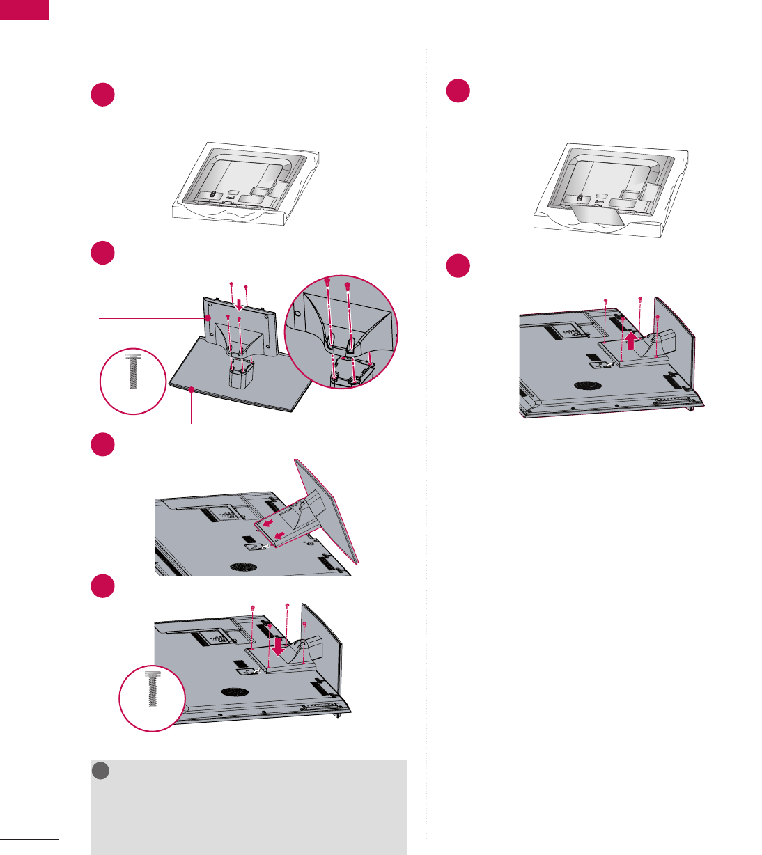
INSTALLATION
1 Carefully place the TV screen side down on a
cushioned surface to protect the screen from
damage.
ὤ㨴㥄
wyv{lj{pvuGjv}ly
AC IN
CABLE MANAGEMEN
T
AC IN
CABLE MANAGEMENT
AC IN
CABLE MANAGEMENT
AC IN
CABLE MANAGEMENT
AC IN
CABLE MANAGEMEN
T
2 Assemble the parts of the STAND BODY with
the STAND BASE of the TV.
ὤ㨴㥄
AC IN
CABLE MANAGEMENT
AC IN
CABLE MANAGEMENT
STAND BODY
STAND BASE
ὤ㨴㥄
AC IN
CABLE MANAGEMENT
AC IN
CABLE MANAGEMENT
ὤ㨴㥄
AC IN
CABLE MANAGEMENT
AC IN
CABLE MANAGEMENT
M4 x 12
3 Insert the stand as shown.
ὤ㨴㥄
AC IN
CABLE MANAGEMENT
AC IN
CABLE MANAGEMENT
4 Install the 4 screws into the holes shown.
ὤ㨴㥄
AC IN
CABLE MANAGEMENT
AC IN
CABLE MANAGEMENT
ὤ㨴㥄
AC IN
CABLE MANAGEMENT
AC IN
CABLE MANAGEMENT
M4 x 12
NOTE
G When assembling the desk type stand, make sure
the screws are fully tightened (If not tightened
fully, the TV can tilt forward after the protuct
installation). Do not over tighten.
!
?
!
?
! !
DETACHMENT
1 Carefully place the TV screen side down on a
cushioned surface to protect the screen from
damage.
ὤ㨴㥄
wyv{lj{pvuGjv}ly
AC IN
CABLE MANAGEMENT
AC IN
CABLE MANAGEMENT
AC IN
CABLE MANAGEMENT
AC IN
CABLE MANAGEMENT
AC IN
CABLE MANAGEMEN
T
2 Remove the four screws that hold the base on.
ὤ㨴㥄
AC IN
CABLE MANAGEMENT
AC IN
CABLE MANAGEMENT
47/55LV555H
PREPARATION
23
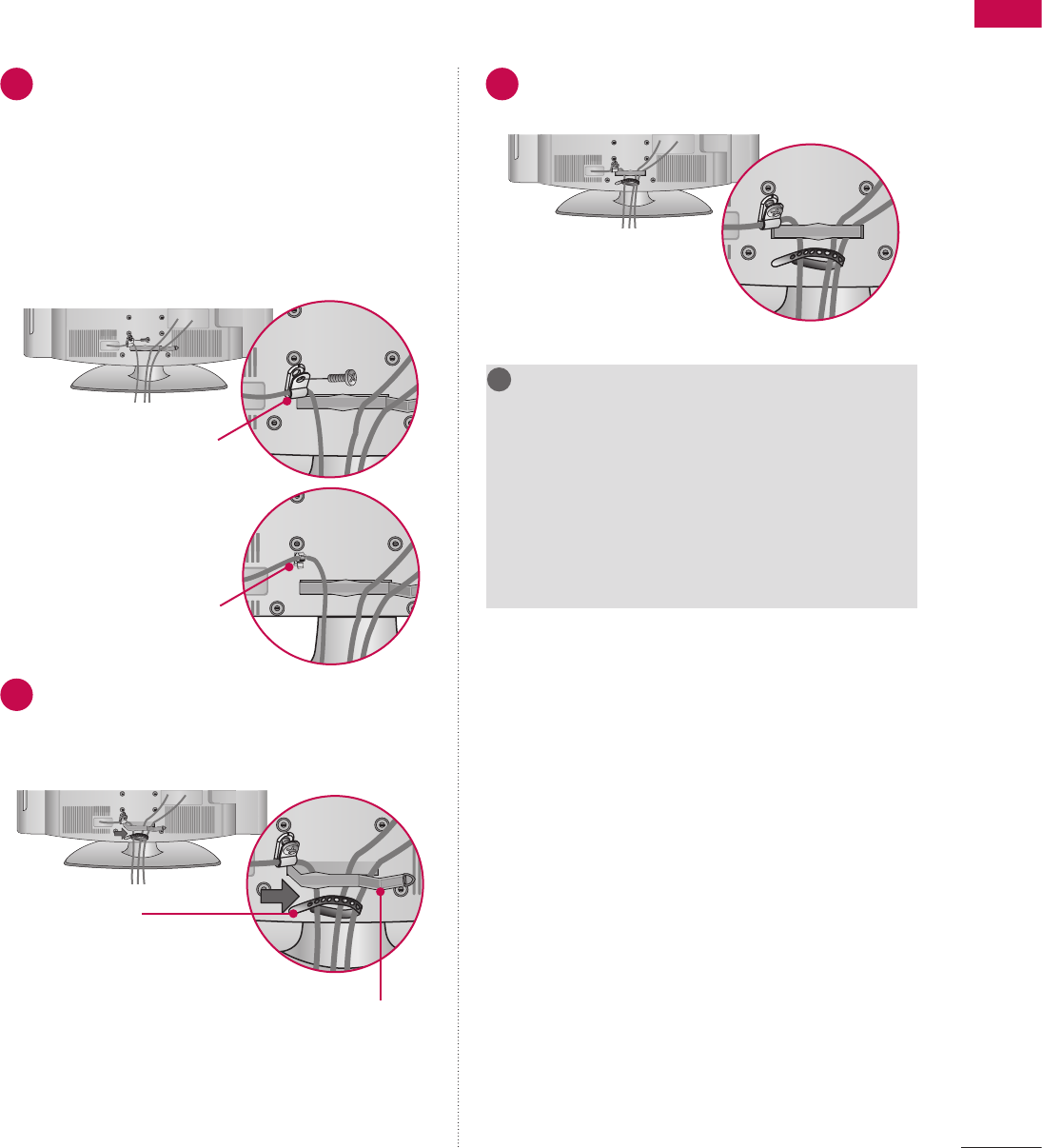
CABLE MANAGEMENT
1 Connect the cables as necessary.
To connect additional equipment, see the
EXTERNAL EQUIPMENT SETUP section.
To help prevent the power cable from being
removed by accident, secure the power cable
with the included PROTECTIVE BRACKET/
SCREW.
The 32LG710H use a PLUG-IN TYPE HOLDER
instead of using a screw.
ὤ㨴㥄
ὤ㨴㥄
ὤ㨴㥄
or
PROTECTIVE BRACKET /SCREW
PLUG-IN TYPE HOLDER
(For 32LG710H model)
2 Open the CABLE MANAGEMENT CLIP as
shown.
If a CABLE HOLDER was included with your TV,
install it as shown.
ὤ㨴㥄
ὤ㨴㥄
CABLE MANAGEMENT CLIP
CABLE HOLDER
3Put the cables inside the CABLE
MANAGEMENT CLIP and snap it closed.
ὤ㨴㥄
ὤ㨴㥄
NOTE
G Do not hold the CABLE MANAGEMENT CLIP
when moving the TV.
- If the TV is dropped, you may be injured or the
product may be broken.
G With some TVs, the PLUG-IN TYPE HOLDER
and the CABLE HOLDER are included. If these
holders are inserted into the hole provided on
back of the TV, they cannot be removed.
!
?
!
?
! !
32/37/42LG710H
V Image shown may differ from your TV.
PREPARATION
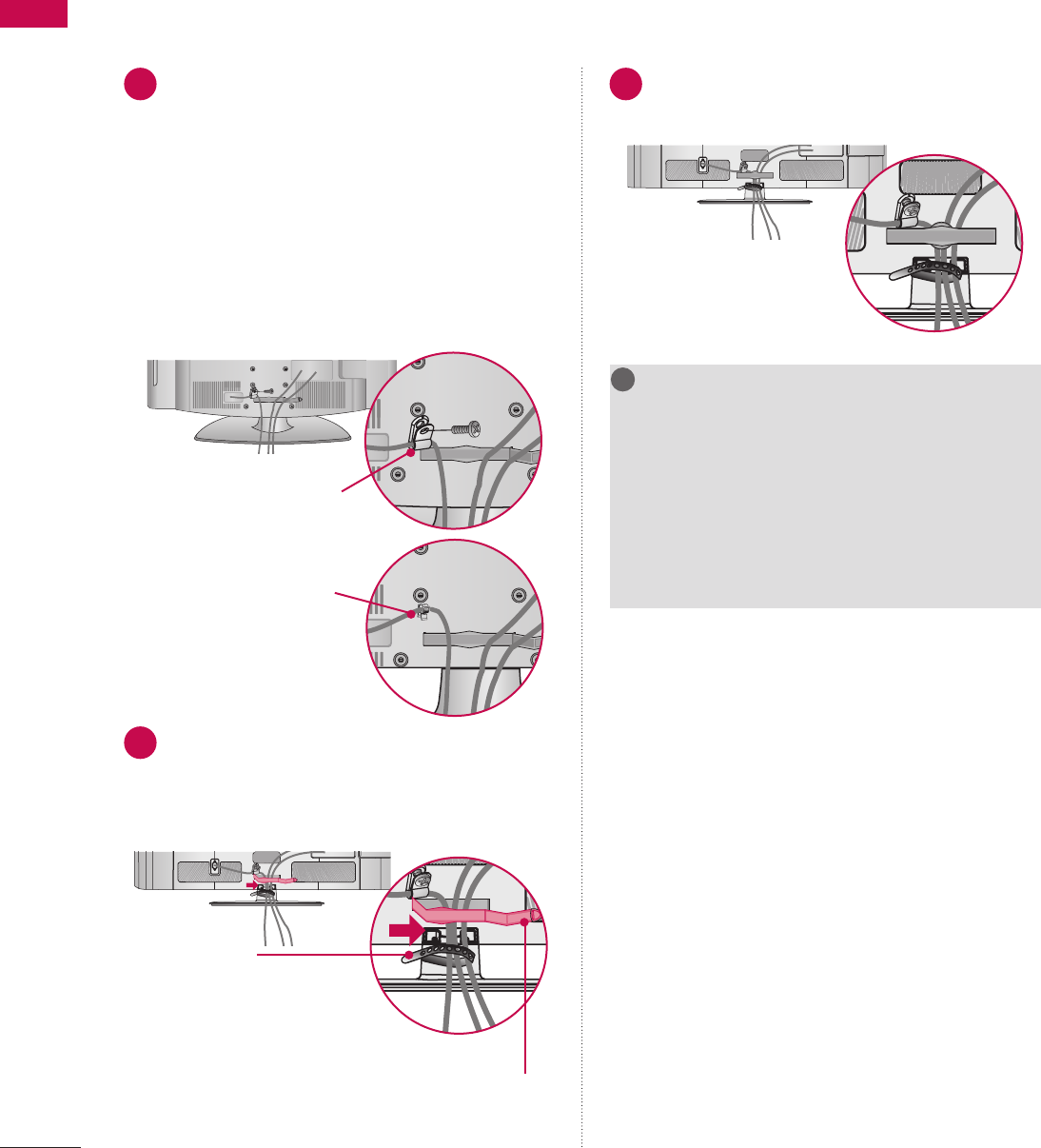
24
PREPARATION
1 Connect the cables as necessary.
To connect additional equipment, see the
EXTERNAL EQUIPMENT SETUP section.
To help prevent the power cable from being
removed by accident, secure the power cable
with the included PROTECTIVE BRACKET /
SCREW.
The 32/37/42LD650H, 32/37/42LD655H,
32/37/42LD660H, 32/37/42LD665H use a
PLUG-IN TYPE HOLDER instead of using a
screw.
ὤ㨴㥄
ὤ㨴㥄
ὤ㨴㥄
or
PROTECTIVE BRACKET /SCREW
PLUG-IN TYPE HOLDER
(For 32/37/42LD650H,
32/37/42LD655H,
32/37/42LD660H,
32/37/42LD665H
model)
2 Open the CABLE MANAGEMENT CLIP as
shown.
If a CABLE HOLDER was included with your TV,
install it as shown.
ὤ㨴㥄
AC IN AC IN
AC IN
ὤ㨴㥄
AC IN AC IN
AC IN
CABLE MANAGEMENT CLIP
CABLE HOLDER
(For 32/37/42LD650H,
32/37/42LD655H,
32/37/42LD660H,
32/37/42LD665H
model)
3Put the cables inside the CABLE
MANAGEMENT CLIP and snap it closed.
ὤ㨴㥄
AC IN AC IN
AC IN
ὤ㨴㥄
AC IN AC IN
AC IN
NOTE
G Do not hold the CABLE MANAGEMENT CLIP
when moving the TV.
- If the TV is dropped, you may be injured or the
product may be broken.
G With some TVs, the PLUG-IN TYPE HOLDER
and the CABLE HOLDER are included. If these
holders are inserted into the hole provided on
back of the TV, they cannot be removed.
!
?
!
?
! !
32/37/42/47/55LD650H, 32/37/42LD655H, 32/37/42LD660H, 32/37/42LD665H
PREPARATION
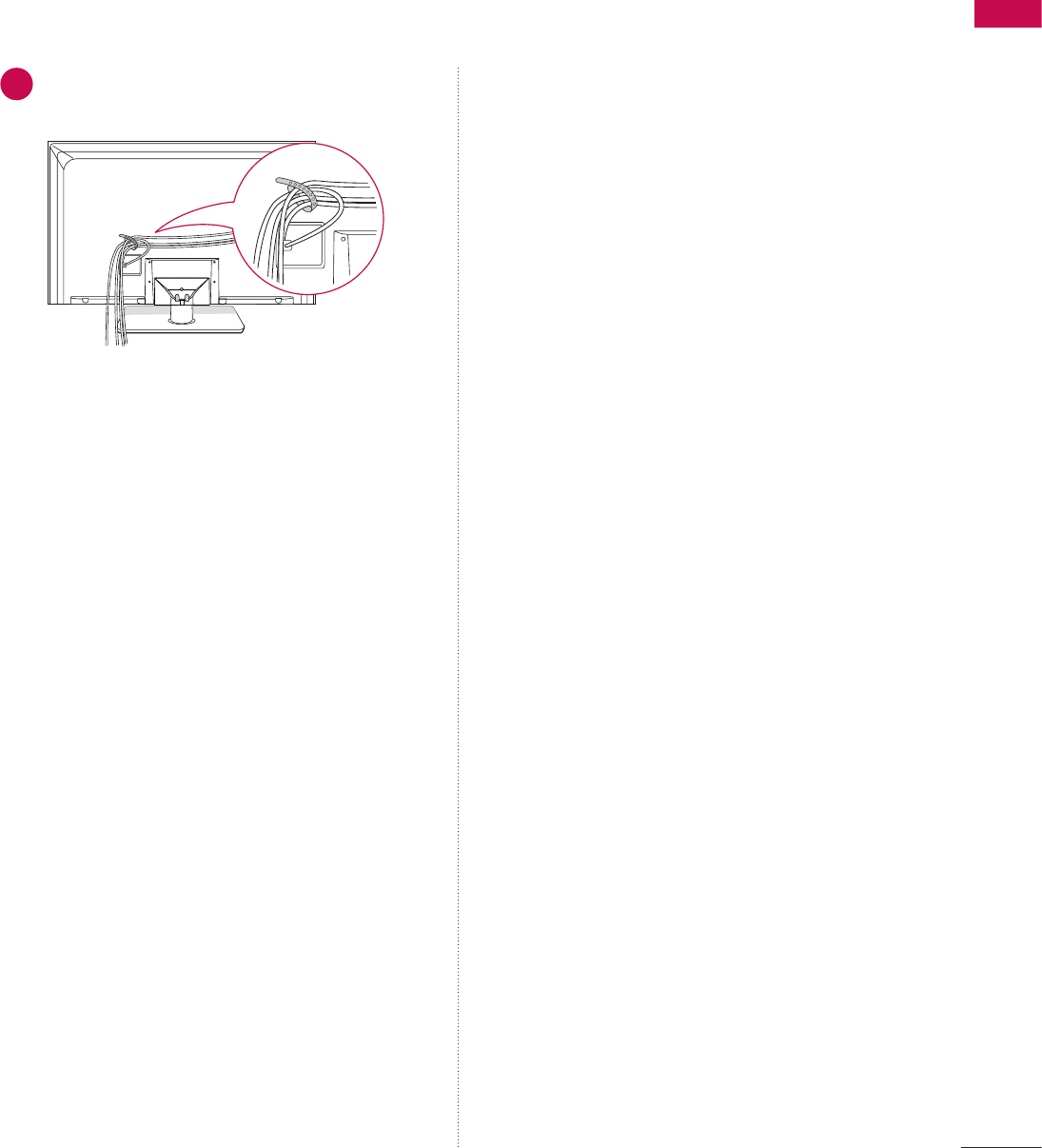
25
1 Gether and bind the cables with the CABLE
HOLDER on the TV back cover.
ὤ㨴㥄
32/37/42/47/55LV555H
PREPARATION
26
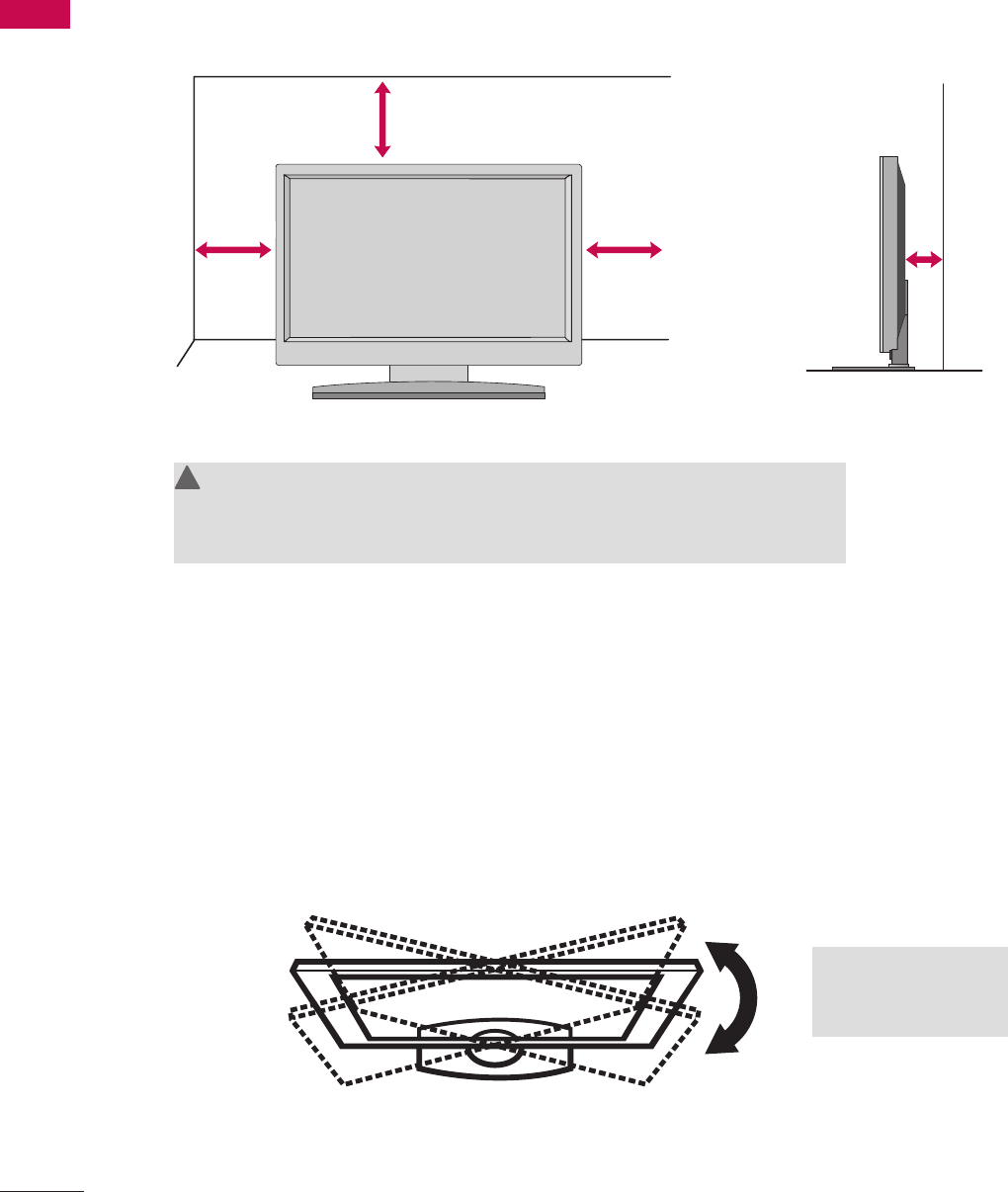
PREPARATION
For proper ventilation, allow a clearance of 4 inches on all four sides from the wall.
After installing the TV, you can adjust the TV set manually to the left or right direction to suit your viewing
position.
4 inches
4 inches 4 inches
4 inches
CAUTION
G Ensure adequate ventilation by following the clearance recommendations.
G Do not mount near or above any type of heat source.
!
?
!
?
! !
20°: 47/55LD650H,
47/55LV555H
90°: Other Models
DESKTOP PEDESTAL INSTALLATION
SWIVEL STAND
V Image shown may differ from your TV.
PREPARATION
27
ὤ㨴㥄
32/37/42LG710H
32/37/42LD650H, 32/37/42LD655H
47/55LD650H
Except 47/55LD650H
ὤ㨴㥄
4-Screws
(not provided as parts of the product)
ὤ㨴㥄
32/37/42LG710H
32/37/42LD650H, 32/37/42LD655H
47/55LD650H
Except 47/55LD650H
ὤ㨴㥄
Desk
Stand
ὤ㨴㥄
32/37/42LG710H
32/37/42LD650H, 32/37/42LD655H
47/55LD650H
Except 47/55LD650H
ὤ㨴㥄
or
Stand
Desk
Type 1 Type 2
2-Screws, 2-Washers, 2-Nuts, 4-Rubbers
(provided as parts of the product)
4-Screws
(not provided as parts of the product)
G Recommended screw size: M5 x L (*L: Table depth + 8~10mm)
ex) Table depth: 15mm, Screw: M5 x 25
G You can select any type of attachment (Type 1 or Type 2)
G Do not over tighten.
ATTACHING THE TV TO A DESK
The TV should be attached to a desk so it cannot be pulled in a forward/backward direction, potentially causing
injury or damaging the product.
32/37/42LD650H, 32/37/42LD655H, 32/37/42LD660H, 32/37/42LD665H, 32/37/42LV555H
32/37/42LG710H
PREPARATION
28
PREPARATION
4-Screws
(not provided as parts of the product)
ὤ㨴㥄
32/37/42LG710H
32/37/42LD650H, 32/37/42LD655H
47/55LD650H
Except 47/55LD650H
ὤ㨴㥄
Stand
Desk
ὤ㨴㥄
32/37/42LG710H
32/37/42LD650H, 32/37/42LD655H
47/55LD650H
Except 47/55LD650H
ὤ㨴㥄
1-Screw
(provided as parts of the product)
Stand
Desk
ὤ㨴㥄
32/37/42LG710H
32/37/42LD650H, 32/37/42LD655H
47/55LD650H
Except 47/55LD650H
ὤ㨴㥄
WARNING
G To prevent TV from falling over, the TV should be securely attached to the floor/wall per installation
instructions. Tipping, shaking, or rocking the TV may cause injury.
!
?
!
?
! !
47/55LD650H, 47/55LV555H
EXCEPT 47/55LD650H, 47/55LV555H
PREPARATION
29
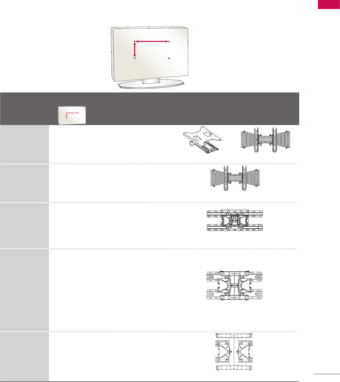
Model
VESA (A * B)
ὤ㨴㥄
y~YZW sz~XWWi sz~YWWi
sz~[WWi
h~T[^snZWt
AA
BB
AA
BB
Standard
Screw Quantity Wall Mounting Bracket
(sold separately)
32LG710H 200 * 100 M4 4
ὤ㨴㥄
y~YZW sz~XWWi sz~YWWi
sz~[WWi
h~T[^snZWt
AA
BB
AA
BB
ὤ㨴㥄
y~YZW sz~XWWi sz~YWWi
sz~[WWi
h~T[^snZWt
AA
BB AA
BB
RW230 AW-47LG30M
37LG710H,
42LG710H 200 * 200 M6 4
ὤ㨴㥄
y~YZW sz~XWWi sz~YWWi
sz~[WWi
h~T[^snZWt
AA
BB AA
BB
AW-47LG30M
32LD650H,
32LD655H,
32LD660H,
32LD665H,
32LV555H
200 * 100 M4 4
ὤ㨴㥄
y~YZW sz~XWWi sz~YWWi
sz~[WWi
h~T[^snZWt
AA
BB AA
BB
LSW100B, LSW100BG
37LD650H,
37LD655H,
37LD660H,
37LD665H,
37LV555H,
42LD650H,
42LD655H,
42LD660H,
42LD665H,
47LD650H
200 * 200 M6 4
ὤ㨴㥄
y~YZW sz~XWWi sz~YWWi
sz~[WWi
h~T[^snZWt
AA
BB AA
BB
LSW200B, LSW200BG
42LV555H,
47LV555H
55LD650H,
55LV555H
400 * 400 M6 4
ὤ㨴㥄
y~YZW sz~XWWi sz~YWWi
sz~[WWi
h~T[^snZWt
AA
BB AA
BB
LSW400B, LSW400BG
ὤ㨴㥄
y~YZW sz~XWWi sz~YWWi
sz~[WWi
h~T[^snZWt
AA
BB
AA
BB
VESA WALL MOUNTING
Install your wall mount on a solid wall perpendicular to the floor. When attaching to other building materials,
please contact an installer. If installed on a ceiling or slanted wall, it may fall and result in severe personal injury.
We recommend that you use an LG brand wall mount when mounting the TV to a wall.
LG recommends that wall mounting be performed by a qualified professional installer.

PREPARATION
30
PREPARATION
NOTE
G Screw length needed depends on the wall mount
used. For further information, refer to the
instructions included with the mount.
G Standard dimensions for wall mount kits are shown
in the table.
G When purchasing our wall mount kit, a detailed
installation manual and all parts necessary for
assembly are provided.
G Do not use screws longer then the standard
dimension, as they may cause damage to the
inside of the TV.
G For wall mounts that do not comply with the VESA
standard screw specifications, the length of the
screws may differ depending on their specifications.
G Do not use screws that do not comply with the
VESA standard screw specifications.
Do not use fasten the screws too strongly, this
may damage the TV or cause the TV to a fall,
leading to personal injury. LG is not liable for these
kinds of accidents.
G LG is not liable for TV damage or personal injury
when a non-VESA or non specified wall mount is
used or the consumer fails to follow the TV
installation instructions.
!
?
!
?
! !
CAUTION
G Do not install your wall mount kit while your TV is turned on. It may result in personal injury due to
electric shock.
!
?
!
?
! !
PREPARATION
31
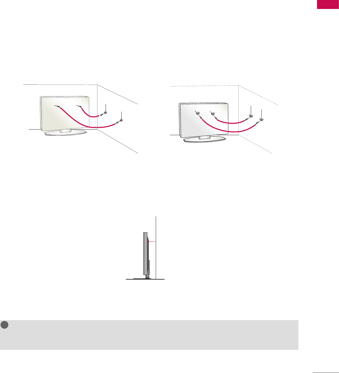
We recommend that you set up the TV close to a wall so it cannot fall over if pushed backwards.
Additionally, we recommend that the TV be attached to a wall so it cannot be pulled in a forward direction,
potentially causing injury or damaging the product.
Caution: Please make sure that children don’t climb on or hang from the TV.
ὤ㨴㥄
V Insert the eye-bolts (or TV brackets and bolts) to tighten the product to the wall as shown in the picture.
* If your product has the bolts in the eye-bolts position before inserting the eye-bolts, loosen the bolts.
* Insert the eye-bolts or TV brackets/bolts and tighten them securely in the upper holes.
Secure the wall brackets with the bolts (sold separately) to the wall. Match the height of the bracket
that is mounted on the wall to the holes in the product.
Ensure the eye-bolts or brackets are tightened securely.
V Use a sturdy rope (sold separately) to tie the product. It is safer to tie the rope so it becomes horizontal between
the wall and the product.
ὤ㨴㥄
NOTE
G Use a platform or cabinet strong enough and large enough to support the size and weight of the TV.
G To use the TV safely make sure that the height of the bracket on the wall and the one on the TV are the same.
!
?
!
?
! !
SECURING THE TV TO THE WALL TO PREVENT
FALLING WHEN THE TV IS USED ON A STAND
V You should purchase necessary components to prevent the TV from tipping over (when not using a wall
mount).
V Image shown may differ from your TV.
PREPARATION
32
PREPARATION
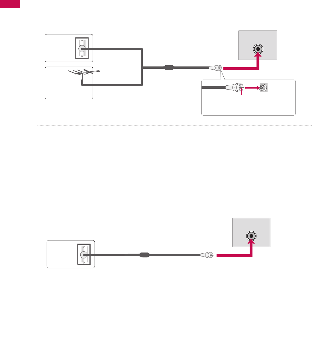
1. Antenna (Analog or Digital)
This image refers to using a Wall Antenna Socket or Outdoor Antenna without a Cable Box Connection.
2. Cable
This image refers to using a cable connection without a cable box.
ὤ㨴㥄
Wall
Antenna
Socket
Outdoor
Antenna
(VHF, UHF)
Multi-family Dwellings/Apartments
(Connect to wall antenna socket)
RF Coaxial Wire (75Ω)
Single-family Dwellings /Houses
(Connect to wall jack for outdoor antenna)
Be careful not to bend the copper wire
when connecting the antenna.
Copper Wire
Cable
TV Wall
Jack
RF Coaxial Wire (75 Ω)
ANTENNA IN
ANTENNA IN
- For optimum picture quality, adjust the antenna direction if needed.
V To improve the picture quality in a poor signal area, please purchase a signal amplifier and install properly.
V If the antenna needs to be split for two TV’s, install a 2-Way Signal Splitter.
V If the antenna is not installed properly, contact your dealer for assistance.
- If you experience a poor signal when using cable, make sure the RF cable is screwed in completely.
Contact your cable company is a poor signal persists.
ANTENNA OR CABLE CONNECTION
V To prevent damage, do not connect to the power outlet until all connections are made between the devices.
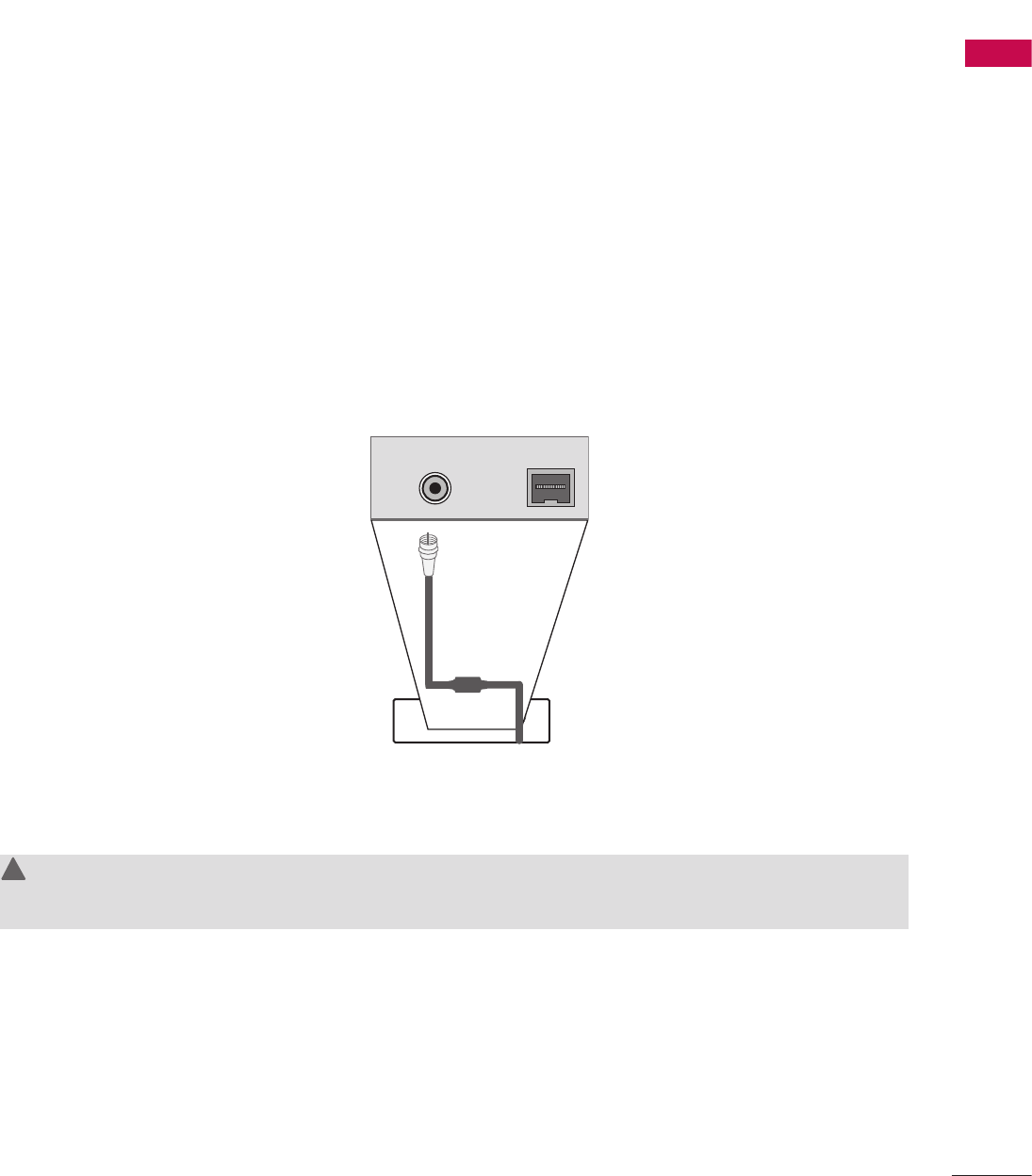
PREPARATION
33
(Except 47/55LD650H, 32/37/42/47/55LV555H)
1. Remove the two MPI card retainer screws.
2. Pull out current MPI card far enough so that the RF cable can be detached from the old card.
3. Detach RF cable.
4. Place new PPV card into slot and slide it in far enough to reconnect RF cable.
5. Insert card all the way into the slot making sure it is fully seated into back plane connector.
6. Replace the two card retainer screws.
MPI Card Removal / PPV Card Installation
ὤ㨴㥄
ANTENNA IN M.P.I.
M.P. I.
Card Slot
RF Cable
WARNING
G There is an RF cable connected to the back of the card. Remove the card slowly.
!
?
!
?
! !
MPI CARD SLOT / PPV CARD INSTALLATION
The MPI card is equipped with an RF jack for antenna/cable signal source connection.
This card can be removed and replaced with a third-party PPV (Pay-Per-View) card.
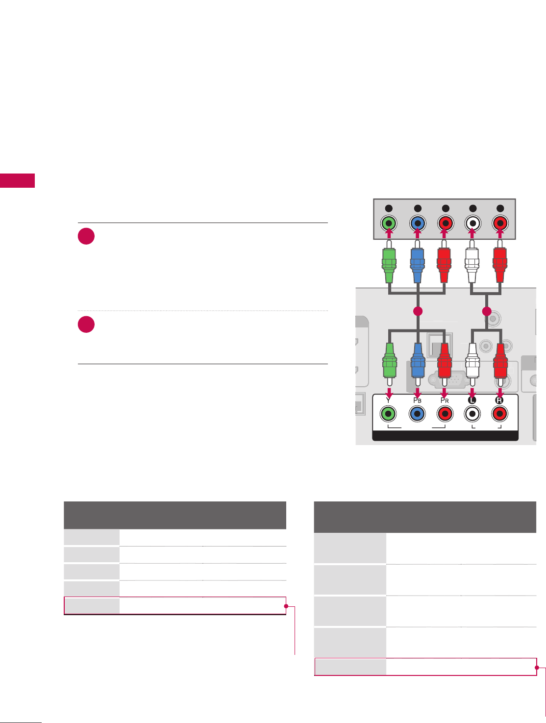
34
EXTERNAL EQUIPMENT SETUP
EXTERNAL EQUIPMENT SETUP
EXTERNAL EQUIPMENT SETUP
HD RECEIVER SETUP
V To prevent the equipment damage, never plug in any power cords until you have finished connecting all equipment.
V Image shown may differ from your TV.
This TV can receive Digital Over-the-air or Digital Cable signals without an external digital set-top box.
However, if you do receive digital signals from a digital set-top box or other digital external device, refer to the
figure as shown below.
1. How to connect
1 Connect the video outputs (Y, PB, PR) of the digital
set-top box to the COMPONENT IN VIDEO jacks on
the TV. Match the jack colors (Y = green, PB = blue,
and PR = red).
2 Connect the audio output of the digital set-top box to
the COMPONENT IN AUDIO jacks on the TV.
2. How to use
V Turn on the digital set-top box.
(Refer to the owner’s manual for the digital set-top box.)
V Select Component input source using the INPUT button
on the remote control.
Component Connection
L R
S-VIDEO VIDEO
OUTPUT
SWITCH
L
R
S
-VIDE
O
VIDE
O
OUTPUT
S
WITC
H
ὤ㨴㥄
REMOTE
CONTROL OUT
OPTICAL
DIGITAL
AUDIO OUT
AV IN 1
AUDIO VIDEO
MONO
/
UPDATE
RESET
LAN
(SERVICE ONLY)
COMPONENT IN
VIDEO AUDIO
HDMI/DVI IN
2
1(DVI)
RJP
INTERFACE
SPEAKER OUT
8
RGB(PC) AUDIO
(RGB/DVI)
RGB IN
RS-232C IN
(SERVICE ONLY)
TV-LINK
CFG
GAME
CONTROL
REMOTE
CONTROL OUT
OPTICAL
DIGITAL
AUDIO OUT
AV IN 1
AUDIO VIDEO
MONO
/
UPDATE
RESET
LAN
(SERVICE ONLY)
COMPONENT IN
VIDEO AUDIO
RJP
INTERFACE
SPEAKER OUT
8
RGB(PC) AUDIO
(RGB/DVI)
RGB IN
RS-232C IN
(SERVICE ONLY)
TV-LINK
CFG
GAME
CONTROL
REMOT
E
C
ONTROL OU
T
O
PTI
C
A
L
D
I
G
ITAL
AUDI
O
O
U
T
AV IN 1
A
U
DI
O
VIDE
O
MONO
MONO
/
UPDATE
R
E
S
E
T
LAN
(
SERVICE ONLY)
CO
MP
O
NENT I
N
VIDE
O
AUDIO
R
J
P
INTERFA
CE
S
PEAKER
OU
T
8
R
G
B(P
C)
AUDIO
(RGB/DVI)
R
G
B IN
RS-232C IN
N
(SERVICE ONLY)
Y)
T
V-LIN
K
C
F
G
G
AM
E
CO
NTR
O
L
HDMI/DVI IN
2
1(DVI)
HDMI-DTV OUTPUT
1
REMOTE
CONTROL OUT
AV IN 1
AUDIO VIDEO
MONO
/
UPDATE
RESET
LAN
(SERVICE ONLY)
COMPONENT IN
VIDEO AUDIO
HDMI/DVI IN
2
1(DVI)
RJP
INTERFACE
SPEAKER OUT
8
RGB(PC) AUDIO
(RGB/DVI)
RGB IN
RS-232C IN
(SERVICE ONLY)
TV-LINK
CFG
GAME
CONTROL
R
EM
O
T
E
CO
NTR
O
L
OUT
AV IN
1
AUDI
O
VIDE
O
MONO
MONO
/
UPDATE
R
E
S
E
T
L
AN
(S
ERVI
C
E
O
NLY)
CO
MP
O
NENT I
N
VIDEO A
U
DI
O
HDMI
/
DVI IN
2
1(DVI
)
RJP
INTERFA
C
E
S
PEAKER
OU
T
8
RG
B
(
P
C)
A
UDIO
(RGB/DVI)
R
G
B I
N
RS-232C IN
N
(SERVICE ONLY)
Y)
T
V-LIN
K
CF
G
G
AME
CO
NTR
OL
OPTICAL
DIGITAL
AUDIO OUT
1
2
REMOTE
CONTROL OUT
OPTICAL
DIGITAL
AUDIO OUT
AV IN 1
AUDIO VIDEO
MONO
/
UPDATE
RESET
LAN
(SERVICE ONLY)
COMPONENT IN
VIDEO AUDIO
RJP
INTERFACE
SPEAKER OUT
8
RS-232C IN
(SERVICE ONLY)
TV-LINK
CFG
GAME
CONTROL
R
EM
O
T
E
CO
NTR
O
L
O
U
T
O
PTICA
L
D
I
G
ITAL
AUDIO OU
T
AV IN
1
A
U
DI
O
VIDE
O
MONO
MONO
/
UPDATE
R
E
S
E
T
LA
N
(
SERVICE ONLY
)
CO
MP
O
NENT I
N
VIDE
O
AUDI
O
R
JP
INTERFA
CE
S
PEAKER
OUT
8
RS-232C IN
N
(SERVICE ONLY)
Y)
TV
-L
INK
C
F
G
G
AME
C
O
NTR
OL
HDMI/DVI IN
2
1(DVI)
RGB(PC) AUDIO
(RGB/DVI)
RGB IN
L R
DVI-DTV OUTPUT LR
1
2
REMOTE
CONTROL OUT
OPTICAL
DIGITAL
AUDIO OUT
UPDATE
RESET
LAN
(SERVICE ONLY)
COMPONENT IN
VIDEO AUDIO
HDMI/DVI IN
2
1(DVI)
RJP
INTERFACE
SPEAKER OUT
8
RGB(PC) AUDIO
(RGB/DVI)
RGB IN
RS-232C IN
(SERVICE ONLY)
TV-LINK
CFG
GAME
CONTROL
R
EMOT
E
CO
NTR
O
L
O
U
T
O
PTICA
L
D
IGITA
L
A
U
DI
O
OUT
UPDATE
RE
S
E
T
LA
N
(SERVICE ONLY
)
C
OMPONENT I
N
VIDEO AUDI
O
H
DMI
/
DVI IN
2
1(DVI)
RJP
I
NTERFA
C
E
S
PEAKER
OU
T
8
RGB(PC
)
AUDI
O
(RGB/DVI)
RG
B IN
RS-232C IN
N
(SERVICE ONLY)
Y)
TV
-L
INK
C
F
G
G
AME
C
O
NTR
OL
AV IN 1
AUDIO VIDEO
MONO
/
L
R
S-VIDEO
VIDEO
OUTPUT
SWITCH
ANT IN
ANT OUT
1
HDMI/DVI IN
2
1(DVI)
REMOTE
CONTROL OUT
OPTICAL
DIGITAL
AUDIO OUT
AV IN 1
AUDIO VIDEO
MONO
/
UPDATE
RESET
LAN
(SERVICE ONLY)
COMPONENT IN
VIDEO AUDIO
RJP
INTERFACE
SPEAKER OUT
8
RS-232C IN
(SERVICE ONLY)
TV-LINK
CFG
GAME
CONTROL
H
DMI
/
DVI IN
2
1
(
DVI
)
R
EM
O
T
E
CO
NTR
O
L
O
U
T
O
PTI
C
A
L
D
I
G
ITA
L
AUDI
O
O
U
T
AV IN
1
A
U
DI
O
VIDE
O
MONO
MONO
/
UPDATE
R
E
S
E
T
LAN
(
SERVICE ONLY
)
CO
MP
O
NENT I
N
VIDE
O
AUDI
O
RJ
P
I
NTERFA
C
E
S
PEAKER
O
UT
8
RS-232C IN
N
(SERVICE ONLY)
Y)
TV
-L
INK
C
F
G
G
AME
CO
NTR
OL
RGB(PC) AUDIO
(RGB/DVI)
RGB IN
AUDIO
RGB OUTPUT
2
1
ὤ㨴㥄
AV IN 2
L/MONO
R
AUDIO
VIDEO
USB IN
L R
VIDEO
1
Camcorder
Video Game Set
ANT IN
ANT OUT
ANTENNA IN M.P.I.
2
1
Wall Jack
Antenna
REMOTE
CONTROL OUT
OPTICAL
DIGITAL
AUDIO OUT
AV IN 1
AUDIO VIDEO
MONO
/
UPDATE
RESET
LAN
(SERVICE ONLY)
HDMI/DVI IN
2
1(DVI)
RJP
INTERFACE
SPEAKER OUT
8
RGB(PC) AUDIO
(RGB/DVI)
RGB IN
RS-232C IN
(SERVICE ONLY)
TV-LINK
CFG
GAME
CONTROL
R
EM
O
T
E
CO
NTR
O
L
OUT
O
PTICA
L
D
IGITAL
A
U
DI
O
OUT
AV IN
1
AUDIO VIDEO
MONO
MONO
/
U
PDAT
E
R
E
S
E
T
LA
N
(SERVICE ONLY
)
HDMI/DVI IN
2
1(DVI
)
RJP
INTERFA
CE
SPEAKER OU
T
8
RGB
(
PC
)
A
U
DI
O
(RGB/DVI)
RG
B IN
RS-232C IN
N
(SERVICE ONLY)
Y)
T
V-LIN
K
CF
G
G
AME
CO
NTR
OL
COMPONENT IN
VIDEO AUDIO
Y L RPBPR
12
Supported Resolutions
Signal Component HDMI
480i Yes No
480p Yes Yes
720p Yes Yes
1080i Yes Yes
1080p Yes Yes
Except 32/37/42LG710H,32LD65H,
32LD655H, 32LD660H,
32LD665H, 32LV555H
Y, CB/PB, CR/PR
Resolution Horizontal
Frequency(kHz)
Vertical
Frequency(Hz)
720x480i 15.73
15.73
59.94
60.00
720x480p 31.47
31.47
59.94
60.00
1280x720p 44.96
45.00
59.94
60.00
1920x1080i 33.72
33.75
59.94
60.00
1920x1080p 67.50 60.00
Except 32/37/42LG710H,32LD65H,
32LD655H, 32LD660H,
32LD665H, 32LV555H
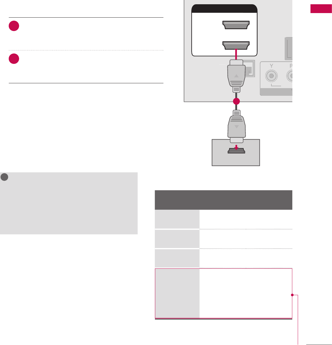
35
EXTERNAL EQUIPMENT SETUP
HDMI Connection
NOTE
G If the HDMI cables don’t support High Speed
HDMI, it can cause flickers or no screen display.
In this case use the latest cables that support
High Speed HDMI.
G HDMI mode supports PCM, Dolby Digital audio
format.
!
?
!
?
! !
1. How to connect
1 Connect the digital set-top box to HDMI/DVI IN 1
(DVI) or 2* jack on the TV.
2 No separate audio connection is necessary.
HDMI supports both audio and video.
2. How to use
V Turn on the digital set-top box.
(Refer to the owner’s manual for the digital set-top box.)
V Select HDMI1 or HDMI2 input source with using the
INPUT button on the remote control.
*HDMI2: Except 32/37/42/47/55LV555H
L R
S-VIDEO VIDEO
OUTPUT
SWITCH
L
R
S
-VIDE
O
VIDE
O
OUTPUT
S
WITC
H
ὤ㨴㥄
REMOTE
CONTROL OUT
OPTICAL
DIGITAL
AUDIO OUT
AV IN 1
AUDIO VIDEO
MONO
/
UPDATE
RESET
LAN
(SERVICE ONLY)
COMPONENT IN
VIDEO AUDIO
HDMI/DVI IN
2
1(DVI)
RJP
INTERFACE
SPEAKER OUT
8
RGB(PC) AUDIO
(RGB/DVI)
RGB IN
RS-232C IN
(SERVICE ONLY)
TV-LINK
CFG
GAME
CONTROL
REMOTE
CONTROL OUT
OPTICAL
DIGITAL
AUDIO OUT
AV IN 1
AUDIO VIDEO
MONO
/
UPDATE
RESET
LAN
(SERVICE ONLY)
COMPONENT IN
VIDEO AUDIO
RJP
INTERFACE
SPEAKER OUT
8
RGB(PC) AUDIO
(RGB/DVI)
RGB IN
RS-232C IN
(SERVICE ONLY)
TV-LINK
CFG
GAME
CONTROL
REMOT
E
C
ONTROL OU
T
O
PTI
C
A
L
D
I
G
ITAL
AUDI
O
O
U
T
AV IN 1
A
U
DI
O
VIDE
O
MONO
MONO
/
UPDATE
R
E
S
E
T
LAN
(
SERVICE ONLY)
CO
MP
O
NENT I
N
VIDE
O
AUDIO
R
J
P
INTERFA
CE
S
PEAKER
OU
T
8
R
G
B(P
C)
AUDIO
(RGB/DVI)
R
G
B IN
RS-232C IN
N
(SERVICE ONLY)
Y)
T
V-LIN
K
C
F
G
G
AM
E
CO
NTR
O
L
HDMI/DVI IN
2
1(DVI)
HDMI-DTV OUTPUT
1
REMOTE
CONTROL OUT
AV IN 1
AUDIO VIDEO
MONO
/
UPDATE
RESET
LAN
(SERVICE ONLY)
COMPONENT IN
VIDEO AUDIO
HDMI/DVI IN
2
1(DVI)
RJP
INTERFACE
SPEAKER OUT
8
RGB(PC) AUDIO
(RGB/DVI)
RGB IN
RS-232C IN
(SERVICE ONLY)
TV-LINK
CFG
GAME
CONTROL
R
EM
O
T
E
CO
NTR
O
L
OUT
AV IN
1
AUDI
O
VIDE
O
MONO
MONO
/
UPDATE
R
E
S
E
T
L
AN
(S
ERVI
C
E
O
NLY)
CO
MP
O
NENT I
N
VIDEO A
U
DI
O
HDMI
/
DVI IN
2
1(DVI
)
RJP
INTERFA
C
E
S
PEAKER
OU
T
8
RG
B
(
P
C)
A
UDIO
(RGB/DVI)
R
G
B I
N
RS-232C IN
N
(SERVICE ONLY)
Y)
T
V-LIN
K
CF
G
G
AME
CO
NTR
OL
OPTICAL
DIGITAL
AUDIO OUT
1
2
REMOTE
CONTROL OUT
OPTICAL
DIGITAL
AUDIO OUT
AV IN 1
AUDIO VIDEO
MONO
/
UPDATE
RESET
LAN
(SERVICE ONLY)
COMPONENT IN
VIDEO AUDIO
RJP
INTERFACE
SPEAKER OUT
8
RS-232C IN
(SERVICE ONLY)
TV-LINK
CFG
GAME
CONTROL
R
EM
O
T
E
CO
NTR
O
L
O
U
T
O
PTICA
L
D
I
G
ITAL
AUDIO OU
T
AV IN
1
A
U
DI
O
VIDE
O
MONO
MONO
/
UPDATE
R
E
S
E
T
LA
N
(
SERVICE ONLY
)
CO
MP
O
NENT I
N
VIDE
O
AUDI
O
R
JP
INTERFA
CE
S
PEAKER
OUT
8
RS-232C IN
N
(SERVICE ONLY)
Y)
TV
-L
INK
C
F
G
G
AME
C
O
NTR
OL
HDMI/DVI IN
2
1(DVI)
RGB(PC) AUDIO
(RGB/DVI)
RGB IN
L R
DVI-DTV OUTPUT LR
1
2
REMOTE
CONTROL OUT
OPTICAL
DIGITAL
AUDIO OUT
UPDATE
RESET
LAN
(SERVICE ONLY)
COMPONENT IN
VIDEO AUDIO
HDMI/DVI IN
2
1(DVI)
RJP
INTERFACE
SPEAKER OUT
8
RGB(PC) AUDIO
(RGB/DVI)
RGB IN
RS-232C IN
(SERVICE ONLY)
TV-LINK
CFG
GAME
CONTROL
R
EMOT
E
CO
NTR
O
L
O
U
T
O
PTICA
L
D
IGITA
L
A
U
DI
O
OUT
UPDATE
RE
S
E
T
LA
N
(SERVICE ONLY
)
C
OMPONENT I
N
VIDEO AUDI
O
H
DMI
/
DVI IN
2
1(DVI)
RJP
I
NTERFA
C
E
S
PEAKER
OU
T
8
RGB(PC
)
AUDI
O
(RGB/DVI)
RG
B IN
RS-232C IN
N
(SERVICE ONLY)
Y)
TV
-L
INK
C
F
G
G
AME
C
O
NTR
OL
AV IN 1
AUDIO VIDEO
MONO
/
L
R
S-VIDEO
VIDEO
OUTPUT
SWITCH
ANT IN
ANT OUT
1
HDMI/DVI IN
2
1(DVI)
REMOTE
CONTROL OUT
OPTICAL
DIGITAL
AUDIO OUT
AV IN 1
AUDIO VIDEO
MONO
/
UPDATE
RESET
LAN
(SERVICE ONLY)
COMPONENT IN
VIDEO AUDIO
RJP
INTERFACE
SPEAKER OUT
8
RS-232C IN
(SERVICE ONLY)
TV-LINK
CFG
GAME
CONTROL
H
DMI
/
DVI IN
2
1
(
DVI
)
R
EM
O
T
E
CO
NTR
O
L
O
U
T
O
PTI
C
A
L
D
I
G
ITA
L
AUDI
O
O
U
T
AV IN
1
A
U
DI
O
VIDE
O
MONO
MONO
/
UPDATE
R
E
S
E
T
LAN
(
SERVICE ONLY
)
CO
MP
O
NENT I
N
VIDE
O
AUDI
O
RJ
P
I
NTERFA
C
E
S
PEAKER
O
UT
8
RS-232C IN
N
(SERVICE ONLY)
Y)
TV
-L
INK
C
F
G
G
AME
CO
NTR
OL
RGB(PC) AUDIO
(RGB/DVI)
RGB IN
AUDIO
RGB OUTPUT
2
1
ὤ㨴㥄
AV IN 2
L/MONO
R
AUDIO
VIDEO
USB IN
L R
VIDEO
1
Camcorder
Video Game Set
ANT IN
ANT OUT
ANTENNA IN M.P.I.
2
1
Wall Jack
Antenna
REMOTE
CONTROL OUT
OPTICAL
DIGITAL
AUDIO OUT
AV IN 1
AUDIO VIDEO
MONO
/
UPDATE
RESET
LAN
(SERVICE ONLY)
HDMI/DVI IN
2
1(DVI)
RJP
INTERFACE
SPEAKER OUT
8
RGB(PC) AUDIO
(RGB/DVI)
RGB IN
RS-232C IN
(SERVICE ONLY)
TV-LINK
CFG
GAME
CONTROL
R
EM
O
T
E
CO
NTR
O
L
OUT
O
PTICA
L
D
IGITAL
A
U
DI
O
OUT
AV IN
1
AUDIO VIDEO
MONO
MONO
/
U
PDAT
E
R
E
S
E
T
LA
N
(SERVICE ONLY
)
HDMI/DVI IN
2
1(DVI
)
RJP
INTERFA
CE
SPEAKER OU
T
8
RGB
(
PC
)
A
U
DI
O
(RGB/DVI)
RG
B IN
RS-232C IN
N
(SERVICE ONLY)
Y)
T
V-LIN
K
CF
G
G
AME
CO
NTR
OL
COMPONENT IN
VIDEO AUDIO
Y L RPBPR
12
HDMI-DTV
Resolution Horizontal
Frequency(kHz)
Vertical
Frequency(Hz)
720x480p 31.47
31.47
59.94
60.00
1280x720p 44.96
45.00
59.94
60.00
1920x1080i 33.72
33.75
59.94
60.00
1920x1080p
26.97
27.00
33.71
33.75
67.432
67.50
23.94
24.00
29.97
30.00
59.939
60.00
Except 32/37/42LG710H,32LD65H,
32LD655H, 32LD660H,
32LD665H, 32LV555H
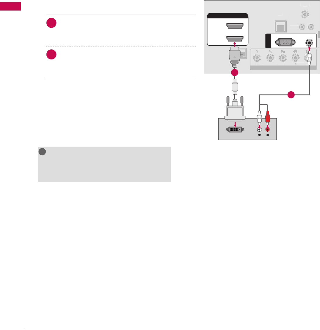
36
EXTERNAL EQUIPMENT SETUP
EXTERNAL EQUIPMENT SETUP
L R
S-VIDEO VIDEO
OUTPUT
SWITCH
L
R
S
-VIDE
O
VIDE
O
OUTPUT
S
WITC
H
ὤ㨴㥄
REMOTE
CONTROL OUT
OPTICAL
DIGITAL
AUDIO OUT
AV IN 1
AUDIO VIDEO
MONO
/
UPDATE
RESET
LAN
(SERVICE ONLY)
COMPONENT IN
VIDEO AUDIO
HDMI/DVI IN
2
1(DVI)
RJP
INTERFACE
SPEAKER OUT
8
RGB(PC) AUDIO
(RGB/DVI)
RGB IN
RS-232C IN
(SERVICE ONLY)
TV-LINK
CFG
GAME
CONTROL
REMOTE
CONTROL OUT
OPTICAL
DIGITAL
AUDIO OUT
AV IN 1
AUDIO VIDEO
MONO
/
UPDATE
RESET
LAN
(SERVICE ONLY)
COMPONENT IN
VIDEO AUDIO
RJP
INTERFACE
SPEAKER OUT
8
RGB(PC) AUDIO
(RGB/DVI)
RGB IN
RS-232C IN
(SERVICE ONLY)
TV-LINK
CFG
GAME
CONTROL
REMOT
E
C
ONTROL OU
T
O
PTI
C
A
L
D
I
G
ITAL
AUDI
O
O
U
T
AV IN 1
A
U
DI
O
VIDE
O
MONO
MONO
/
UPDATE
R
E
S
E
T
LAN
(
SERVICE ONLY)
CO
MP
O
NENT I
N
VIDE
O
AUDIO
R
J
P
INTERFA
CE
S
PEAKER
OU
T
8
R
G
B(P
C)
AUDIO
(RGB/DVI)
R
G
B IN
RS-232C IN
N
(SERVICE ONLY)
Y)
T
V-LIN
K
C
F
G
G
AM
E
CO
NTR
O
L
HDMI/DVI IN
2
1(DVI)
HDMI-DTV OUTPUT
1
REMOTE
CONTROL OUT
AV IN 1
AUDIO VIDEO
MONO
/
UPDATE
RESET
LAN
(SERVICE ONLY)
COMPONENT IN
VIDEO AUDIO
HDMI/DVI IN
2
1(DVI)
RJP
INTERFACE
SPEAKER OUT
8
RGB(PC) AUDIO
(RGB/DVI)
RGB IN
RS-232C IN
(SERVICE ONLY)
TV-LINK
CFG
GAME
CONTROL
R
EM
O
T
E
CO
NTR
O
L
OUT
AV IN
1
AUDI
O
VIDE
O
MONO
MONO
/
UPDATE
R
E
S
E
T
L
AN
(S
ERVI
C
E
O
NLY)
CO
MP
O
NENT I
N
VIDEO A
U
DI
O
HDMI
/
DVI IN
2
1(DVI
)
RJP
INTERFA
C
E
S
PEAKER
OU
T
8
RG
B
(
P
C)
A
UDIO
(RGB/DVI)
R
G
B I
N
RS-232C IN
N
(SERVICE ONLY)
Y)
T
V-LIN
K
CF
G
G
AME
CO
NTR
OL
OPTICAL
DIGITAL
AUDIO OUT
1
2
REMOTE
CONTROL OUT
OPTICAL
DIGITAL
AUDIO OUT
AV IN 1
AUDIO VIDEO
MONO
/
UPDATE
RESET
LAN
(SERVICE ONLY)
COMPONENT IN
VIDEO AUDIO
RJP
INTERFACE
SPEAKER OUT
8
RS-232C IN
(SERVICE ONLY)
TV-LINK
CFG
GAME
CONTROL
R
EM
O
T
E
CO
NTR
O
L
O
U
T
O
PTICA
L
D
I
G
ITAL
AUDIO OU
T
AV IN
1
A
U
DI
O
VIDE
O
MONO
MONO
/
UPDATE
R
E
S
E
T
LA
N
(
SERVICE ONLY
)
CO
MP
O
NENT I
N
VIDE
O
AUDI
O
R
JP
INTERFA
CE
S
PEAKER
OUT
8
RS-232C IN
N
(SERVICE ONLY)
Y)
TV
-L
INK
C
F
G
G
AME
C
O
NTR
OL
HDMI/DVI IN
2
1(DVI)
RGB(PC) AUDIO
(RGB/DVI)
RGB IN
L R
DVI-DTV OUTPUT LR
1
2
REMOTE
CONTROL OUT
OPTICAL
DIGITAL
AUDIO OUT
UPDATE
RESET
LAN
(SERVICE ONLY)
COMPONENT IN
VIDEO AUDIO
HDMI/DVI IN
2
1(DVI)
RJP
INTERFACE
SPEAKER OUT
8
RGB(PC) AUDIO
(RGB/DVI)
RGB IN
RS-232C IN
(SERVICE ONLY)
TV-LINK
CFG
GAME
CONTROL
R
EMOT
E
CO
NTR
O
L
O
U
T
O
PTICA
L
D
IGITA
L
A
U
DI
O
OUT
UPDATE
RE
S
E
T
LA
N
(SERVICE ONLY
)
C
OMPONENT I
N
VIDEO AUDI
O
H
DMI
/
DVI IN
2
1(DVI)
RJP
I
NTERFA
C
E
S
PEAKER
OU
T
8
RGB(PC
)
AUDI
O
(RGB/DVI)
RG
B IN
RS-232C IN
N
(SERVICE ONLY)
Y)
TV
-L
INK
C
F
G
G
AME
C
O
NTR
OL
AV IN 1
AUDIO VIDEO
MONO
/
L
R
S-VIDEO
VIDEO
OUTPUT
SWITCH
ANT IN
ANT OUT
1
HDMI/DVI IN
2
1(DVI)
REMOTE
CONTROL OUT
OPTICAL
DIGITAL
AUDIO OUT
AV IN 1
AUDIO VIDEO
MONO
/
UPDATE
RESET
LAN
(SERVICE ONLY)
COMPONENT IN
VIDEO AUDIO
RJP
INTERFACE
SPEAKER OUT
8
RS-232C IN
(SERVICE ONLY)
TV-LINK
CFG
GAME
CONTROL
H
DMI
/
DVI IN
2
1
(
DVI
)
R
EM
O
T
E
CO
NTR
O
L
O
U
T
O
PTI
C
A
L
D
I
G
ITA
L
AUDI
O
O
U
T
AV IN
1
A
U
DI
O
VIDE
O
MONO
MONO
/
UPDATE
R
E
S
E
T
LAN
(
SERVICE ONLY
)
CO
MP
O
NENT I
N
VIDE
O
AUDI
O
RJ
P
I
NTERFA
C
E
S
PEAKER
O
UT
8
RS-232C IN
N
(SERVICE ONLY)
Y)
TV
-L
INK
C
F
G
G
AME
CO
NTR
OL
RGB(PC) AUDIO
(RGB/DVI)
RGB IN
AUDIO
RGB OUTPUT
2
1
ὤ㨴㥄
AV IN 2
L/MONO
R
AUDIO
VIDEO
USB IN
L R
VIDEO
1
Camcorder
Video Game Set
ANT IN
ANT OUT
ANTENNA IN M.P.I.
2
1
Wall Jack
Antenna
REMOTE
CONTROL OUT
OPTICAL
DIGITAL
AUDIO OUT
AV IN 1
AUDIO VIDEO
MONO
/
UPDATE
RESET
LAN
(SERVICE ONLY)
HDMI/DVI IN
2
1(DVI)
RJP
INTERFACE
SPEAKER OUT
8
RGB(PC) AUDIO
(RGB/DVI)
RGB IN
RS-232C IN
(SERVICE ONLY)
TV-LINK
CFG
GAME
CONTROL
R
EM
O
T
E
CO
NTR
O
L
OUT
O
PTICA
L
D
IGITAL
A
U
DI
O
OUT
AV IN
1
AUDIO VIDEO
MONO
MONO
/
U
PDAT
E
R
E
S
E
T
LA
N
(SERVICE ONLY
)
HDMI/DVI IN
2
1(DVI
)
RJP
INTERFA
CE
SPEAKER OU
T
8
RGB
(
PC
)
A
U
DI
O
(RGB/DVI)
RG
B IN
RS-232C IN
N
(SERVICE ONLY)
Y)
T
V-LIN
K
CF
G
G
AME
CO
NTR
OL
COMPONENT IN
VIDEO AUDIO
Y L RPBPR
12
NOTE
G A DVI to HDMI cable or adapter is required for
this connection. DVI doesn't support audio, so a
separate audio connection is necessary.
!
?
!
?
! !
DVI to HDMI Connection
1. How to connect
1 Connect the DVI output of the digital set-top box to
the HDMI/DVI IN 1 (DVI) jack on the TV.
2 Connect the audio output of the digital set-top box to
the AUDIO (RGB/DVI) jack on the TV.
2. How to use
V Turn on the digital set-top box.
(Refer to the owner’s manual for the digital set-top box.)
V Select the HDMI1 input source on the TV using the
INPUT button on the remote control.
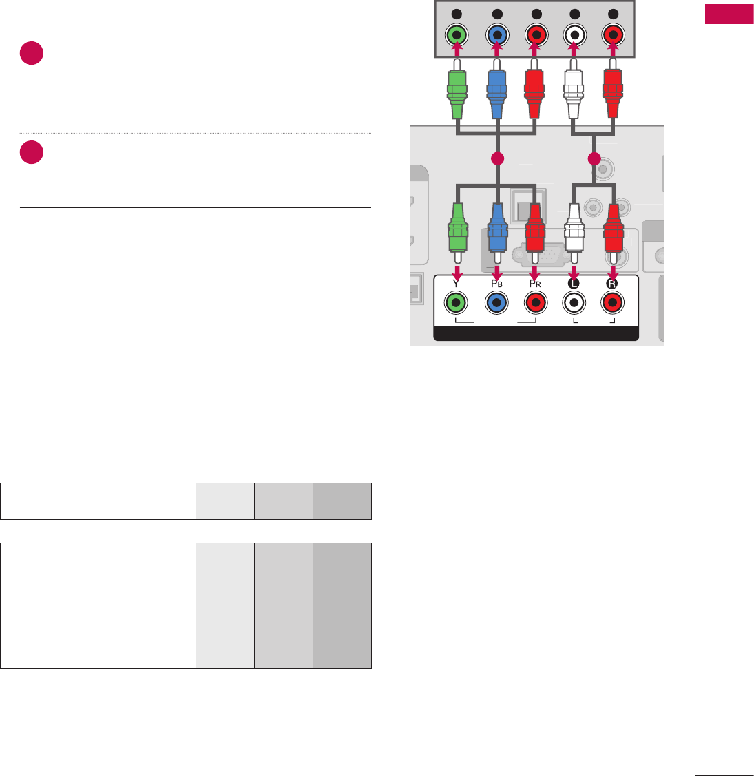
37
EXTERNAL EQUIPMENT SETUP
Component Input ports
To get better picture quality, connect a DVD player to the component input ports as shown below.
L R
S-VIDEO VIDEO
OUTPUT
SWITCH
L
R
S
-VIDE
O
VIDE
O
OUTPUT
S
WITC
H
ὤ㨴㥄
REMOTE
CONTROL OUT
OPTICAL
DIGITAL
AUDIO OUT
AV IN 1
AUDIO VIDEO
MONO
/
UPDATE
RESET
LAN
(SERVICE ONLY)
COMPONENT IN
VIDEO AUDIO
HDMI/DVI IN
2
1(DVI)
RJP
INTERFACE
SPEAKER OUT
8
RGB(PC) AUDIO
(RGB/DVI)
RGB IN
RS-232C IN
(SERVICE ONLY)
TV-LINK
CFG
GAME
CONTROL
REMOTE
CONTROL OUT
OPTICAL
DIGITAL
AUDIO OUT
AV IN 1
AUDIO VIDEO
MONO
/
UPDATE
RESET
LAN
(SERVICE ONLY)
COMPONENT IN
VIDEO AUDIO
RJP
INTERFACE
SPEAKER OUT
8
RGB(PC) AUDIO
(RGB/DVI)
RGB IN
RS-232C IN
(SERVICE ONLY)
TV-LINK
CFG
GAME
CONTROL
REMOT
E
C
ONTROL OU
T
O
PTI
C
A
L
D
I
G
ITAL
AUDI
O
O
U
T
AV IN 1
A
U
DI
O
VIDE
O
MONO
MONO
/
UPDATE
R
E
S
E
T
LAN
(
SERVICE ONLY)
CO
MP
O
NENT I
N
VIDE
O
AUDIO
R
J
P
INTERFA
CE
S
PEAKER
OU
T
8
R
G
B(P
C)
AUDIO
(RGB/DVI)
R
G
B IN
RS-232C IN
N
(SERVICE ONLY)
Y)
T
V-LIN
K
C
F
G
G
AM
E
CO
NTR
O
L
HDMI/DVI IN
2
1(DVI)
HDMI-DTV OUTPUT
1
REMOTE
CONTROL OUT
AV IN 1
AUDIO VIDEO
MONO
/
UPDATE
RESET
LAN
(SERVICE ONLY)
COMPONENT IN
VIDEO AUDIO
HDMI/DVI IN
2
1(DVI)
RJP
INTERFACE
SPEAKER OUT
8
RGB(PC) AUDIO
(RGB/DVI)
RGB IN
RS-232C IN
(SERVICE ONLY)
TV-LINK
CFG
GAME
CONTROL
R
EM
O
T
E
CO
NTR
O
L
OUT
AV IN
1
AUDI
O
VIDE
O
MONO
MONO
/
UPDATE
R
E
S
E
T
L
AN
(S
ERVI
C
E
O
NLY)
CO
MP
O
NENT I
N
VIDEO A
U
DI
O
HDMI
/
DVI IN
2
1(DVI
)
RJP
INTERFA
C
E
S
PEAKER
OU
T
8
RG
B
(
P
C)
A
UDIO
(RGB/DVI)
R
G
B I
N
RS-232C IN
N
(SERVICE ONLY)
Y)
T
V-LIN
K
CF
G
G
AME
CO
NTR
OL
OPTICAL
DIGITAL
AUDIO OUT
1
2
REMOTE
CONTROL OUT
OPTICAL
DIGITAL
AUDIO OUT
AV IN 1
AUDIO VIDEO
MONO
/
UPDATE
RESET
LAN
(SERVICE ONLY)
COMPONENT IN
VIDEO AUDIO
RJP
INTERFACE
SPEAKER OUT
8
RS-232C IN
(SERVICE ONLY)
TV-LINK
CFG
GAME
CONTROL
R
EM
O
T
E
CO
NTR
O
L
O
U
T
O
PTICA
L
D
I
G
ITAL
AUDIO OU
T
AV IN
1
A
U
DI
O
VIDE
O
MONO
MONO
/
UPDATE
R
E
S
E
T
LA
N
(
SERVICE ONLY
)
CO
MP
O
NENT I
N
VIDE
O
AUDI
O
R
JP
INTERFA
CE
S
PEAKER
OUT
8
RS-232C IN
N
(SERVICE ONLY)
Y)
TV
-L
INK
C
F
G
G
AME
C
O
NTR
OL
HDMI/DVI IN
2
1(DVI)
RGB(PC) AUDIO
(RGB/DVI)
RGB IN
L R
DVI-DTV OUTPUT LR
1
2
REMOTE
CONTROL OUT
OPTICAL
DIGITAL
AUDIO OUT
UPDATE
RESET
LAN
(SERVICE ONLY)
COMPONENT IN
VIDEO AUDIO
HDMI/DVI IN
2
1(DVI)
RJP
INTERFACE
SPEAKER OUT
8
RGB(PC) AUDIO
(RGB/DVI)
RGB IN
RS-232C IN
(SERVICE ONLY)
TV-LINK
CFG
GAME
CONTROL
R
EMOT
E
CO
NTR
O
L
O
U
T
O
PTICA
L
D
IGITA
L
A
U
DI
O
OUT
UPDATE
RE
S
E
T
LA
N
(SERVICE ONLY
)
C
OMPONENT I
N
VIDEO AUDI
O
H
DMI
/
DVI IN
2
1(DVI)
RJP
I
NTERFA
C
E
S
PEAKER
OU
T
8
RGB(PC
)
AUDI
O
(RGB/DVI)
RG
B IN
RS-232C IN
N
(SERVICE ONLY)
Y)
TV
-L
INK
C
F
G
G
AME
C
O
NTR
OL
AV IN 1
AUDIO VIDEO
MONO
/
L
R
S-VIDEO
VIDEO
OUTPUT
SWITCH
ANT IN
ANT OUT
1
HDMI/DVI IN
2
1(DVI)
REMOTE
CONTROL OUT
OPTICAL
DIGITAL
AUDIO OUT
AV IN 1
AUDIO VIDEO
MONO
/
UPDATE
RESET
LAN
(SERVICE ONLY)
COMPONENT IN
VIDEO AUDIO
RJP
INTERFACE
SPEAKER OUT
8
RS-232C IN
(SERVICE ONLY)
TV-LINK
CFG
GAME
CONTROL
H
DMI
/
DVI IN
2
1
(
DVI
)
R
EM
O
T
E
CO
NTR
O
L
O
U
T
O
PTI
C
A
L
D
I
G
ITA
L
AUDI
O
O
U
T
AV IN
1
A
U
DI
O
VIDE
O
MONO
MONO
/
UPDATE
R
E
S
E
T
LAN
(
SERVICE ONLY
)
CO
MP
O
NENT I
N
VIDE
O
AUDI
O
RJ
P
I
NTERFA
C
E
S
PEAKER
O
UT
8
RS-232C IN
N
(SERVICE ONLY)
Y)
TV
-L
INK
C
F
G
G
AME
CO
NTR
OL
RGB(PC) AUDIO
(RGB/DVI)
RGB IN
AUDIO
RGB OUTPUT
2
1
ὤ㨴㥄
AV IN 2
L/MONO
R
AUDIO
VIDEO
USB IN
L R
VIDEO
1
Camcorder
Video Game Set
ANT IN
ANT OUT
ANTENNA IN M.P.I.
2
1
Wall Jack
Antenna
REMOTE
CONTROL OUT
OPTICAL
DIGITAL
AUDIO OUT
AV IN 1
AUDIO VIDEO
MONO
/
UPDATE
RESET
LAN
(SERVICE ONLY)
HDMI/DVI IN
2
1(DVI)
RJP
INTERFACE
SPEAKER OUT
8
RGB(PC) AUDIO
(RGB/DVI)
RGB IN
RS-232C IN
(SERVICE ONLY)
TV-LINK
CFG
GAME
CONTROL
R
EM
O
T
E
CO
NTR
O
L
OUT
O
PTICA
L
D
IGITAL
A
U
DI
O
OUT
AV IN
1
AUDIO VIDEO
MONO
MONO
/
U
PDAT
E
R
E
S
E
T
LA
N
(SERVICE ONLY
)
HDMI/DVI IN
2
1(DVI
)
RJP
INTERFA
CE
SPEAKER OU
T
8
RGB
(
PC
)
A
U
DI
O
(RGB/DVI)
RG
B IN
RS-232C IN
N
(SERVICE ONLY)
Y)
T
V-LIN
K
CF
G
G
AME
CO
NTR
OL
COMPONENT IN
VIDEO AUDIO
Y L RPBPR
12
DVD SETUP
Component ports on the TV Y PBPR
Video output ports
on DVD player
Y PBPR
Y B-Y R-Y
Y CBCR
Y PBPR
Component Connection
1. How to connect
1 Connect the video outputs (Y, PB, PR) of the DVD to
the COMPONENT IN VIDEO jacks on the TV. Match
the jack colors (Y = green, PB = blue, and PR = red).
2 Connect the audio outputs of the DVD to the
COMPONENT IN AUDIO jacks on the TV.
2. How to use
V Turn on the DVD player, insert a DVD.
V Select the Component input source on the TV using the
INPUT button on the remote control.
V Refer to the DVD player's manual for operating
instructions.
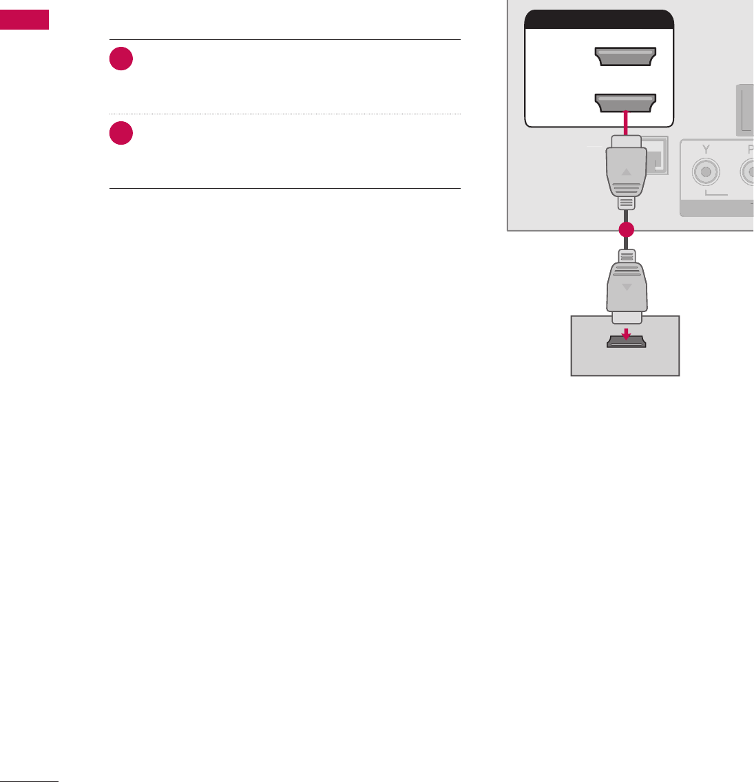
38
EXTERNAL EQUIPMENT SETUP
EXTERNAL EQUIPMENT SETUP
L R
S-VIDEO VIDEO
OUTPUT
SWITCH
L
R
S
-VIDE
O
VIDE
O
OUTPUT
S
WITC
H
ὤ㨴㥄
REMOTE
CONTROL OUT
OPTICAL
DIGITAL
AUDIO OUT
AV IN 1
AUDIO VIDEO
MONO
/
UPDATE
RESET
LAN
(SERVICE ONLY)
COMPONENT IN
VIDEO AUDIO
HDMI/DVI IN
2
1(DVI)
RJP
INTERFACE
SPEAKER OUT
8
RGB(PC) AUDIO
(RGB/DVI)
RGB IN
RS-232C IN
(SERVICE ONLY)
TV-LINK
CFG
GAME
CONTROL
REMOTE
CONTROL OUT
OPTICAL
DIGITAL
AUDIO OUT
AV IN 1
AUDIO VIDEO
MONO
/
UPDATE
RESET
LAN
(SERVICE ONLY)
COMPONENT IN
VIDEO AUDIO
RJP
INTERFACE
SPEAKER OUT
8
RGB(PC) AUDIO
(RGB/DVI)
RGB IN
RS-232C IN
(SERVICE ONLY)
TV-LINK
CFG
GAME
CONTROL
REMOT
E
C
ONTROL OU
T
O
PTI
C
A
L
D
I
G
ITAL
AUDI
O
O
U
T
AV IN 1
A
U
DI
O
VIDE
O
MONO
MONO
/
UPDATE
R
E
S
E
T
LAN
(
SERVICE ONLY)
CO
MP
O
NENT I
N
VIDE
O
AUDIO
R
J
P
INTERFA
CE
S
PEAKER
OU
T
8
R
G
B(P
C)
AUDIO
(RGB/DVI)
R
G
B IN
RS-232C IN
N
(SERVICE ONLY)
Y)
T
V-LIN
K
C
F
G
G
AM
E
CO
NTR
O
L
HDMI/DVI IN
2
1(DVI)
HDMI-DTV OUTPUT
1
REMOTE
CONTROL OUT
AV IN 1
AUDIO VIDEO
MONO
/
UPDATE
RESET
LAN
(SERVICE ONLY)
COMPONENT IN
VIDEO AUDIO
HDMI/DVI IN
2
1(DVI)
RJP
INTERFACE
SPEAKER OUT
8
RGB(PC) AUDIO
(RGB/DVI)
RGB IN
RS-232C IN
(SERVICE ONLY)
TV-LINK
CFG
GAME
CONTROL
R
EM
O
T
E
CO
NTR
O
L
OUT
AV IN
1
AUDI
O
VIDE
O
MONO
MONO
/
UPDATE
R
E
S
E
T
L
AN
(S
ERVI
C
E
O
NLY)
CO
MP
O
NENT I
N
VIDEO A
U
DI
O
HDMI
/
DVI IN
2
1(DVI
)
RJP
INTERFA
C
E
S
PEAKER
OU
T
8
RG
B
(
P
C)
A
UDIO
(RGB/DVI)
R
G
B I
N
RS-232C IN
N
(SERVICE ONLY)
Y)
T
V-LIN
K
CF
G
G
AME
CO
NTR
OL
OPTICAL
DIGITAL
AUDIO OUT
1
2
REMOTE
CONTROL OUT
OPTICAL
DIGITAL
AUDIO OUT
AV IN 1
AUDIO VIDEO
MONO
/
UPDATE
RESET
LAN
(SERVICE ONLY)
COMPONENT IN
VIDEO AUDIO
RJP
INTERFACE
SPEAKER OUT
8
RS-232C IN
(SERVICE ONLY)
TV-LINK
CFG
GAME
CONTROL
R
EM
O
T
E
CO
NTR
O
L
O
U
T
O
PTICA
L
D
I
G
ITAL
AUDIO OU
T
AV IN
1
A
U
DI
O
VIDE
O
MONO
MONO
/
UPDATE
R
E
S
E
T
LA
N
(
SERVICE ONLY
)
CO
MP
O
NENT I
N
VIDE
O
AUDI
O
R
JP
INTERFA
CE
S
PEAKER
OUT
8
RS-232C IN
N
(SERVICE ONLY)
Y)
TV
-L
INK
C
F
G
G
AME
C
O
NTR
OL
HDMI/DVI IN
2
1(DVI)
RGB(PC) AUDIO
(RGB/DVI)
RGB IN
L R
DVI-DTV OUTPUT LR
1
2
REMOTE
CONTROL OUT
OPTICAL
DIGITAL
AUDIO OUT
UPDATE
RESET
LAN
(SERVICE ONLY)
COMPONENT IN
VIDEO AUDIO
HDMI/DVI IN
2
1(DVI)
RJP
INTERFACE
SPEAKER OUT
8
RGB(PC) AUDIO
(RGB/DVI)
RGB IN
RS-232C IN
(SERVICE ONLY)
TV-LINK
CFG
GAME
CONTROL
R
EMOT
E
CO
NTR
O
L
O
U
T
O
PTICA
L
D
IGITA
L
A
U
DI
O
OUT
UPDATE
RE
S
E
T
LA
N
(SERVICE ONLY
)
C
OMPONENT I
N
VIDEO AUDI
O
H
DMI
/
DVI IN
2
1(DVI)
RJP
I
NTERFA
C
E
S
PEAKER
OU
T
8
RGB(PC
)
AUDI
O
(RGB/DVI)
RG
B IN
RS-232C IN
N
(SERVICE ONLY)
Y)
TV
-L
INK
C
F
G
G
AME
C
O
NTR
OL
AV IN 1
AUDIO VIDEO
MONO
/
L
R
S-VIDEO
VIDEO
OUTPUT
SWITCH
ANT IN
ANT OUT
1
HDMI/DVI IN
2
1(DVI)
REMOTE
CONTROL OUT
OPTICAL
DIGITAL
AUDIO OUT
AV IN 1
AUDIO VIDEO
MONO
/
UPDATE
RESET
LAN
(SERVICE ONLY)
COMPONENT IN
VIDEO AUDIO
RJP
INTERFACE
SPEAKER OUT
8
RS-232C IN
(SERVICE ONLY)
TV-LINK
CFG
GAME
CONTROL
H
DMI
/
DVI IN
2
1
(
DVI
)
R
EM
O
T
E
CO
NTR
O
L
O
U
T
O
PTI
C
A
L
D
I
G
ITA
L
AUDI
O
O
U
T
AV IN
1
A
U
DI
O
VIDE
O
MONO
MONO
/
UPDATE
R
E
S
E
T
LAN
(
SERVICE ONLY
)
CO
MP
O
NENT I
N
VIDE
O
AUDI
O
RJ
P
I
NTERFA
C
E
S
PEAKER
O
UT
8
RS-232C IN
N
(SERVICE ONLY)
Y)
TV
-L
INK
C
F
G
G
AME
CO
NTR
OL
RGB(PC) AUDIO
(RGB/DVI)
RGB IN
AUDIO
RGB OUTPUT
2
1
ὤ㨴㥄
AV IN 2
L/MONO
R
AUDIO
VIDEO
USB IN
L R
VIDEO
1
Camcorder
Video Game Set
ANT IN
ANT OUT
ANTENNA IN M.P.I.
2
1
Wall Jack
Antenna
REMOTE
CONTROL OUT
OPTICAL
DIGITAL
AUDIO OUT
AV IN 1
AUDIO VIDEO
MONO
/
UPDATE
RESET
LAN
(SERVICE ONLY)
HDMI/DVI IN
2
1(DVI)
RJP
INTERFACE
SPEAKER OUT
8
RGB(PC) AUDIO
(RGB/DVI)
RGB IN
RS-232C IN
(SERVICE ONLY)
TV-LINK
CFG
GAME
CONTROL
R
EM
O
T
E
CO
NTR
O
L
OUT
O
PTICA
L
D
IGITAL
A
U
DI
O
OUT
AV IN
1
AUDIO VIDEO
MONO
MONO
/
U
PDAT
E
R
E
S
E
T
LA
N
(SERVICE ONLY
)
HDMI/DVI IN
2
1(DVI
)
RJP
INTERFA
CE
SPEAKER OU
T
8
RGB
(
PC
)
A
U
DI
O
(RGB/DVI)
RG
B IN
RS-232C IN
N
(SERVICE ONLY)
Y)
T
V-LIN
K
CF
G
G
AME
CO
NTR
OL
COMPONENT IN
VIDEO AUDIO
Y L RPBPR
12
HDMI Connection
1. How to connect
1 Connect the HDMI output of the DVD to the HDMI/
DVI IN 1 (DVI) or 2* jack on the TV.
2 No separate audio connection is necessary.
HDMI supports both audio and video.
2. How to use
V Select the HDMI1 or HDMI2 input source on the TV
using the INPUT button on the remote control.
V Refer to the DVD player's manual for operating
instructions.
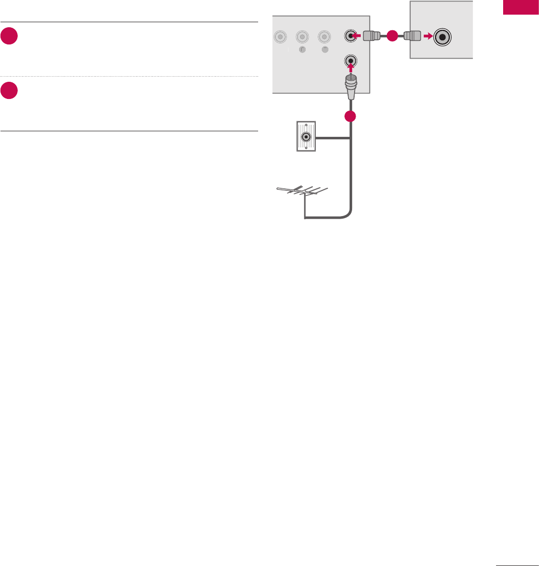
39
EXTERNAL EQUIPMENT SETUP
L R
S-VIDEO VIDEO
OUTPUT
SWITCH
L
R
S
-VIDE
O
VIDE
O
OUTPUT
S
WITC
H
ὤ㨴㥄
REMOTE
CONTROL OUT
OPTICAL
DIGITAL
AUDIO OUT
AV IN 1
AUDIO VIDEO
MONO
/
UPDATE
RESET
LAN
(SERVICE ONLY)
COMPONENT IN
VIDEO AUDIO
HDMI/DVI IN
2
1(DVI)
RJP
INTERFACE
SPEAKER OUT
8
RGB(PC) AUDIO
(RGB/DVI)
RGB IN
RS-232C IN
(SERVICE ONLY)
TV-LINK
CFG
GAME
CONTROL
REMOTE
CONTROL OUT
OPTICAL
DIGITAL
AUDIO OUT
AV IN 1
AUDIO VIDEO
MONO
/
UPDATE
RESET
LAN
(SERVICE ONLY)
COMPONENT IN
VIDEO AUDIO
RJP
INTERFACE
SPEAKER OUT
8
RGB(PC) AUDIO
(RGB/DVI)
RGB IN
RS-232C IN
(SERVICE ONLY)
TV-LINK
CFG
GAME
CONTROL
REMOT
E
C
ONTROL OU
T
O
PTI
C
A
L
D
I
G
ITAL
AUDI
O
O
U
T
AV IN 1
A
U
DI
O
VIDE
O
MONO
MONO
/
UPDATE
R
E
S
E
T
LAN
(
SERVICE ONLY)
CO
MP
O
NENT I
N
VIDE
O
AUDIO
R
J
P
INTERFA
CE
S
PEAKER
OU
T
8
R
G
B(P
C)
AUDIO
(RGB/DVI)
R
G
B IN
RS-232C IN
N
(SERVICE ONLY)Y)
T
V-LIN
K
C
F
G
G
AM
E
CO
NTR
O
L
HDMI/DVI IN
2
1(DVI)
HDMI-DTV OUTPUT
1
REMOTE
CONTROL OUT
AV IN 1
AUDIO VIDEO
MONO
/
UPDATE
RESET
LAN
(SERVICE ONLY)
COMPONENT IN
VIDEO AUDIO
HDMI/DVI IN
2
1(DVI)
RJP
INTERFACE
SPEAKER OUT
8
RGB(PC) AUDIO
(RGB/DVI)
RGB IN
RS-232C IN
(SERVICE ONLY)
TV-LINK
CFG
GAME
CONTROL
R
EM
O
T
E
CO
NTR
O
L
OUT
AV IN
1
AUDI
O
VIDE
O
MONO
MONO
/
UPDATE
R
E
S
E
T
L
AN
(S
ERVI
C
E
O
NLY)
CO
MP
O
NENT I
N
VIDEO A
U
DI
O
HDMI
/
DVI IN
2
1(DVI
)
RJP
INTERFA
C
E
S
PEAKER
OU
T
8
RG
B
(
P
C)
A
UDIO
(RGB/DVI)
R
G
B I
N
RS-232C IN
N
(SERVICE ONLY)
Y)
T
V-LIN
K
CF
G
G
AME
CO
NTR
OL
OPTICAL
DIGITAL
AUDIO OUT
1
2
REMOTE
CONTROL OUT
OPTICAL
DIGITAL
AUDIO OUT
AV IN 1
AUDIO VIDEO
MONO
/
UPDATE
RESET
LAN
(SERVICE ONLY)
COMPONENT IN
VIDEO AUDIO
RJP
INTERFACE
SPEAKER OUT
8
RS-232C IN
(SERVICE ONLY)
TV-LINK
CFG
GAME
CONTROL
R
EM
O
T
E
CO
NTR
O
L
O
U
T
O
PTICA
L
D
I
G
ITAL
AUDIO OU
T
AV IN
1
A
U
DI
O
VIDE
O
MONO
MONO
/
UPDATE
R
E
S
E
T
LA
N
(
SERVICE ONLY
)
CO
MP
O
NENT I
N
VIDE
O
AUDI
O
R
JP
INTERFA
CE
S
PEAKER
OUT
8
RS-232C IN
N
(SERVICE ONLY)Y)
TV
-L
INK
C
F
G
G
AME
C
O
NTR
OL
HDMI/DVI IN
2
1(DVI)
RGB(PC) AUDIO
(RGB/DVI)
RGB IN
L R
DVI-DTV OUTPUT LR
1
2
REMOTE
CONTROL OUT
OPTICAL
DIGITAL
AUDIO OUT
UPDATE
RESET
LAN
(SERVICE ONLY)
COMPONENT IN
VIDEO AUDIO
HDMI/DVI IN
2
1(DVI)
RJP
INTERFACE
SPEAKER OUT
8
RGB(PC) AUDIO
(RGB/DVI)
RGB IN
RS-232C IN
(SERVICE ONLY)
TV-LINK
CFG
GAME
CONTROL
R
EMOT
E
CO
NTR
O
L
O
U
T
O
PTICA
L
D
IGITA
L
A
U
DI
O
OUT
UPDATE
RE
S
E
T
LA
N
(SERVICE ONLY
)
C
OMPONENT I
N
VIDEO AUDI
O
H
DMI
/
DVI IN
2
1(DVI)
RJP
I
NTERFA
C
E
S
PEAKER
OU
T
8
RGB(PC
)
AUDI
O
(RGB/DVI)
RG
B IN
RS-232C IN
N
(SERVICE ONLY)
Y)
TV
-L
INK
C
F
G
G
AME
C
O
NTR
OL
AV IN 1
AUDIO VIDEO
MONO
/
L
R
S-VIDEO
VIDEO
OUTPUT
SWITCH
ANT IN
ANT OUT
1
HDMI/DVI IN
2
1(DVI)
REMOTE
CONTROL OUT
OPTICAL
DIGITAL
AUDIO OUT
AV IN 1
AUDIO VIDEO
MONO
/
UPDATE
RESET
LAN
(SERVICE ONLY)
COMPONENT IN
VIDEO AUDIO
RJP
INTERFACE
SPEAKER OUT
8
RS-232C IN
(SERVICE ONLY)
TV-LINK
CFG
GAME
CONTROL
H
DMI
/
DVI IN
2
1
(
DVI
)
R
EM
O
T
E
CO
NTR
O
L
O
U
T
O
PTI
C
A
L
D
I
G
ITA
L
AUDI
O
O
U
T
AV IN
1
A
U
DI
O
VIDE
O
MONO
MONO
/
UPDATE
R
E
S
E
T
LAN
(
SERVICE ONLY
)
CO
MP
O
NENT I
N
VIDE
O
AUDI
O
RJ
P
I
NTERFA
C
E
S
PEAKER
O
UT
8
RS-232C IN
N
(SERVICE ONLY)
Y)
TV
-L
INK
C
F
G
G
AME
CO
NTR
OL
RGB(PC) AUDIO
(RGB/DVI)
RGB IN
AUDIO
RGB OUTPUT
2
1
ὤ㨴㥄
AV IN 2
L/MONO
R
AUDIO
VIDEO
USB IN
L R
VIDEO
1
Camcorder
Video Game Set
ANT IN
ANT OUT
ANTENNA IN
M.P.I.
2
1
Wall Jack
Antenna
REMOTE
CONTROL OUT
OPTICAL
DIGITAL
AUDIO OUT
AV IN 1
AUDIO VIDEO
MONO
/
UPDATE
RESET
LAN
(SERVICE ONLY)
HDMI/DVI IN
2
1(DVI)
RJP
INTERFACE
SPEAKER OUT
8
RGB(PC) AUDIO
(RGB/DVI)
RGB IN
RS-232C IN
(SERVICE ONLY)
TV-LINK
CFG
GAME
CONTROL
R
EM
O
T
E
CO
NTR
O
L
OUT
O
PTICA
L
D
IGITAL
A
U
DI
O
OUT
AV IN
1
AUDIO VIDEO
MONO
MONO
/
U
PDAT
E
R
E
S
E
T
LA
N
(SERVICE ONLY
)
HDMI/DVI IN
2
1(DVI
)
RJP
INTERFA
CE
SPEAKER OU
T
8
RGB
(
PC
)
A
U
DI
O
(RGB/DVI)
RG
B IN
RS-232C IN
N
(SERVICE ONLY)Y)
T
V-LIN
K
CF
G
G
AME
CO
NTR
OL
COMPONENT IN
VIDEO AUDIO
Y L RPBPR
12
VCR SETUP
V To avoid picture noise (interference), leave an adequate distance between the VCR and TV.
Antenna Connection
1. How to connect
1 Connect the RF antenna out socket of the VCR to the
ANTENNA IN socket on the TV.
2 Connect the antenna cable to the RF antenna in
socket of the VCR.
2. How to use
V Set VCR output switch to 3 or 4 and then tune TV to the
same channel number.
V Insert a video tape into the VCR and press PLAY on the
VCR. (Refer to the VCR owner’s manual.)
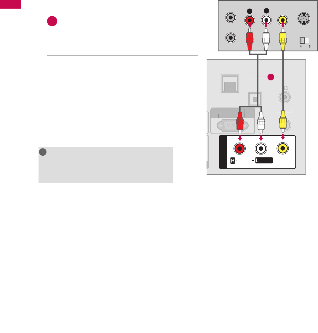
40
EXTERNAL EQUIPMENT SETUP
EXTERNAL EQUIPMENT SETUP
L R
S-VIDEO VIDEO
OUTPUT
SWITCH
L
R
S
-VIDE
O
VIDE
O
OUTPUT
S
WITC
H
ὤ㨴㥄
REMOTE
CONTROL OUT
OPTICAL
DIGITAL
AUDIO OUT
AV IN 1
AUDIO VIDEO
MONO
/
UPDATE
RESET
LAN
(SERVICE ONLY)
COMPONENT IN
VIDEO AUDIO
HDMI/DVI IN
2
1(DVI)
RJP
INTERFACE
SPEAKER OUT
8
RGB(PC) AUDIO
(RGB/DVI)
RGB IN
RS-232C IN
(SERVICE ONLY)
TV-LINK
CFG
GAME
CONTROL
REMOTE
CONTROL OUT
OPTICAL
DIGITAL
AUDIO OUT
AV IN 1
AUDIO VIDEO
MONO
/
UPDATE
RESET
LAN
(SERVICE ONLY)
COMPONENT IN
VIDEO AUDIO
RJP
INTERFACE
SPEAKER OUT
8
RGB(PC) AUDIO
(RGB/DVI)
RGB IN
RS-232C IN
(SERVICE ONLY)
TV-LINK
CFG
GAME
CONTROL
REMOT
E
C
ONTROL OU
T
O
PTI
C
A
L
D
I
G
ITAL
AUDI
O
O
U
T
AV IN 1
A
U
DI
O
VIDE
O
MONO
MONO
/
UPDATE
R
E
S
E
T
LAN
(
SERVICE ONLY)
CO
MP
O
NENT I
N
VIDE
O
AUDIO
R
J
P
INTERFA
CE
S
PEAKER
OU
T
8
R
G
B(P
C)
AUDIO
(RGB/DVI)
R
G
B IN
RS-232C IN
N
(SERVICE ONLY)Y)
T
V-LIN
K
C
F
G
G
AM
E
CO
NTR
O
L
HDMI/DVI IN
2
1(DVI)
HDMI-DTV OUTPUT
1
REMOTE
CONTROL OUT
AV IN 1
AUDIO VIDEO
MONO
/
UPDATE
RESET
LAN
(SERVICE ONLY)
COMPONENT IN
VIDEO AUDIO
HDMI/DVI IN
2
1(DVI)
RJP
INTERFACE
SPEAKER OUT
8
RGB(PC) AUDIO
(RGB/DVI)
RGB IN
RS-232C IN
(SERVICE ONLY)
TV-LINK
CFG
GAME
CONTROL
R
EM
O
T
E
CO
NTR
O
L
OUT
AV IN
1
AUDI
O
VIDE
O
MONO
MONO
/
UPDATE
R
E
S
E
T
L
AN
(S
ERVI
C
E
O
NLY)
CO
MP
O
NENT I
N
VIDEO A
U
DI
O
HDMI
/
DVI IN
2
1(DVI
)
RJP
INTERFA
C
E
S
PEAKER
OU
T
8
RG
B
(
P
C)
A
UDIO
(RGB/DVI)
R
G
B I
N
RS-232C IN
N
(SERVICE ONLY)
Y)
T
V-LIN
K
CF
G
G
AME
CO
NTR
OL
OPTICAL
DIGITAL
AUDIO OUT
1
2
REMOTE
CONTROL OUT
OPTICAL
DIGITAL
AUDIO OUT
AV IN 1
AUDIO VIDEO
MONO
/
UPDATE
RESET
LAN
(SERVICE ONLY)
COMPONENT IN
VIDEO AUDIO
RJP
INTERFACE
SPEAKER OUT
8
RS-232C IN
(SERVICE ONLY)
TV-LINK
CFG
GAME
CONTROL
R
EM
O
T
E
CO
NTR
O
L
O
U
T
O
PTICA
L
D
I
G
ITAL
AUDIO OU
T
AV IN
1
A
U
DI
O
VIDE
O
MONO
MONO
/
UPDATE
R
E
S
E
T
LA
N
(
SERVICE ONLY
)
CO
MP
O
NENT I
N
VIDE
O
AUDI
O
R
JP
INTERFA
CE
S
PEAKER
OUT
8
RS-232C IN
N
(SERVICE ONLY)Y)
TV
-L
INK
C
F
G
G
AME
C
O
NTR
OL
HDMI/DVI IN
2
1(DVI)
RGB(PC) AUDIO
(RGB/DVI)
RGB IN
L R
DVI-DTV OUTPUT LR
1
2
REMOTE
CONTROL OUT
OPTICAL
DIGITAL
AUDIO OUT
UPDA
TE
RESET
LAN
(SERVICE ONLY)
COMPONENT IN
VIDEO AUDIO
HDMI/DVI IN
2
1(DVI)
RJP
INTERFACE
SPEAKER OUT
8
RGB(PC) AUDIO
(RGB/DVI)
RGB IN
RS-232C IN
(SERVICE ONLY)
TV-LINK
CFG
GAME
CONTROL
R
EMOT
E
CO
NTR
O
L
O
U
T
O
PTICA
L
D
IGITA
L
A
U
DI
O
OUT
UPDATE
RE
S
E
T
LA
N
(SERVICE ONLY
)
C
OMPONENT I
N
VIDEO AUDI
O
H
DMI
/
DVI IN
2
1(DVI)
RJP
I
NTERFA
C
E
S
PEAKER
OU
T
8
RGB(PC
)
AUDI
O
(RGB/DVI)
RG
B IN
RS-232C IN
N
(SERVICE ONLY)
Y)
TV
-L
INK
C
F
G
G
AME
C
O
NTR
OL
AV IN 1
AUDIO VIDEO
MONO
/
L
R
S-VIDEO
VIDEO
OUTPUT
SWITCH
ANT IN
ANT OUT
1
HDMI/DVI IN
2
1(DVI)
REMOTE
CONTROL OUT
OPTICAL
DIGITAL
AUDIO OUT
AV IN 1
AUDIO VIDEO
MONO
/
UPDATE
RESET
LAN
(SERVICE ONLY)
COMPONENT IN
VIDEO AUDIO
RJP
INTERFACE
SPEAKER OUT
8
RS-232C IN
(SERVICE ONLY)
TV-LINK
CFG
GAME
CONTROL
H
DMI
/
DVI IN
2
1
(
DVI
)
R
EM
O
T
E
CO
NTR
O
L
O
U
T
O
PTI
C
A
L
D
I
G
ITA
L
AUDI
O
O
U
T
AV IN
1
A
U
DI
O
VIDE
O
MONO
MONO
/
UPDATE
R
E
S
E
T
LAN
(
SERVICE ONLY
)
CO
MP
O
NENT I
N
VIDE
O
AUDI
O
RJ
P
I
NTERFA
C
E
S
PEAKER
O
UT
8
RS-232C IN
N
(SERVICE ONLY)
Y)
TV
-L
INK
C
F
G
G
AME
CO
NTR
OL
RGB(PC) AUDIO
(RGB/DVI)
RGB IN
AUDIO
RGB OUTPUT
2
1
ὤ㨴㥄
AV IN 2
L/MONO
R
AUDIO
VIDEO
USB IN
L R
VIDEO
1
Camcorder
Video Game Set
ANT IN
ANT OUT
ANTENNA IN M.P.I.
2
1
Wall Jack
Antenna
REMOTE
CONTROL OUT
OPTICAL
DIGITAL
AUDIO OUT
AV IN 1
AUDIO VIDEO
MONO
/
UPDATE
RESET
LAN
(SERVICE ONLY)
HDMI/DVI IN
2
1(DVI)
RJP
INTERFACE
SPEAKER OUT
8
RGB(PC) AUDIO
(RGB/DVI)
RGB IN
RS-232C IN
(SERVICE ONLY)
TV-LINK
CFG
GAME
CONTROL
R
EM
O
T
E
CO
NTR
O
L
OUT
O
PTICA
L
D
IGITAL
A
U
DI
O
OUT
AV IN
1
AUDIO VIDEO
MONO
MONO
/
U
PDAT
E
R
E
S
E
T
LA
N
(SERVICE ONLY
)
HDMI/DVI IN
2
1(DVI
)
RJP
INTERFA
CE
SPEAKER OU
T
8
RGB
(
PC
)
A
U
DI
O
(RGB/DVI)
RG
B IN
RS-232C IN
N
(SERVICE ONLY)
Y)
T
V-LIN
K
CF
G
G
AME
CO
NTR
OL
COMPONENT IN
VIDEO AUDIO
Y L RPBPR
12
NOTE
G If you have a mono VCR, connect the audio
cable from the VCR to the AUDIO L/MONO
jack of the TV.
!
?
!
?
! !
Composite (RCA) Connection
1. How to connect
1 Connect the AUDIO/VIDEO jacks between TV and
VCR. Match the jack colors (Video = yellow, Audio Left
= white, and Audio Right = red).
2. How to use
V Insert a video tape into the VCR and press PLAY on the
VCR. (Refer to the VCR owner’s manual.)
V Select the AV1 input source on the TV using the INPUT
button on the remote control.
V If connected to AV IN 2, select AV2 input source on the
TV.
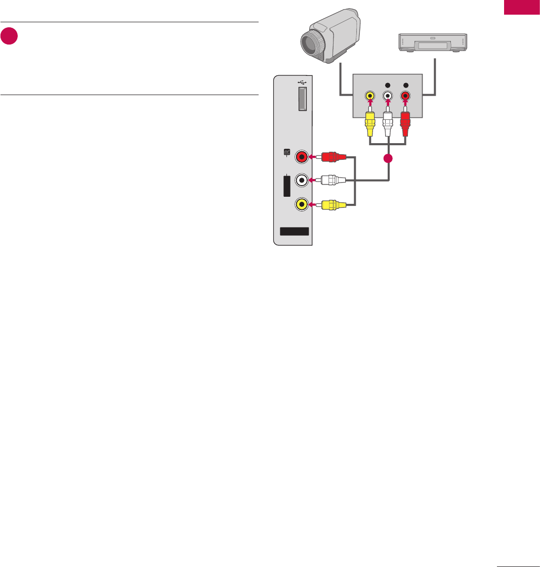
41
EXTERNAL EQUIPMENT SETUP
L R
S-VIDEO VIDEO
OUTPUT
SWITCH
L
R
S
-VIDE
O
VIDE
O
OUTPUT
S
WITC
H
ὤ㨴㥄
REMOTE
CONTROL OUT
OPTICAL
DIGITAL
AUDIO OUT
AV IN 1
AUDIO VIDEO
MONO
/
UPDATE
RESET
LAN
(SERVICE ONLY)
COMPONENT IN
VIDEO AUDIO
HDMI/DVI IN
2
1(DVI)
RJP
INTERFACE
SPEAKER OUT
8
RGB(PC) AUDIO
(RGB/DVI)
RGB IN
RS-232C IN
(SERVICE ONLY)
TV-LINK
CFG
GAME
CONTROL
REMOTE
CONTROL OUT
OPTICAL
DIGITAL
AUDIO OUT
AV IN 1
AUDIO VIDEO
MONO
/
UPDATE
RESET
LAN
(SERVICE ONLY)
COMPONENT IN
VIDEO AUDIO
RJP
INTERFACE
SPEAKER OUT
8
RGB(PC) AUDIO
(RGB/DVI)
RGB IN
RS-232C IN
(SERVICE ONLY)
TV-LINK
CFG
GAME
CONTROL
REMOT
E
C
ONTROL OU
T
O
PTI
C
A
L
D
I
G
ITAL
AUDI
O
O
U
T
AV IN 1
A
U
DI
O
VIDE
O
MONO
MONO
/
UPDATE
R
E
S
E
T
LAN
(
SERVICE ONLY)
CO
MP
O
NENT I
N
VIDE
O
AUDIO
R
J
P
INTERFA
CE
S
PEAKER
OU
T
8
R
G
B(P
C)
AUDIO
(RGB/DVI)
R
G
B IN
RS-232C IN
N
(SERVICE ONLY)
Y)
T
V-LIN
K
C
F
G
G
AM
E
CO
NTR
O
L
HDMI/DVI IN
2
1(DVI)
HDMI-DTV OUTPUT
1
REMOTE
CONTROL OUT
AV IN 1
AUDIO VIDEO
MONO
/
UPDATE
RESET
LAN
(SERVICE ONLY)
COMPONENT IN
VIDEO AUDIO
HDMI/DVI IN
2
1(DVI)
RJP
INTERFACE
SPEAKER OUT
8
RGB(PC) AUDIO
(RGB/DVI)
RGB IN
RS-232C IN
(SERVICE ONLY)
TV-LINK
CFG
GAME
CONTROL
R
EM
O
T
E
CO
NTR
O
L
OUT
AV IN
1
AUDI
O
VIDE
O
MONO
MONO
/
UPDATE
R
E
S
E
T
L
AN
(S
ERVI
C
E
O
NLY)
CO
MP
O
NENT I
N
VIDEO A
U
DI
O
HDMI
/
DVI IN
2
1(DVI
)
RJP
INTERFA
C
E
S
PEAKER
OU
T
8
RG
B
(
P
C)
A
UDIO
(RGB/DVI)
R
G
B I
N
RS-232C IN
N
(SERVICE ONLY)
Y)
T
V-LIN
K
CF
G
G
AME
CO
NTR
OL
OPTICAL
DIGITAL
AUDIO OUT
1
2
REMOTE
CONTROL OUT
OPTICAL
DIGITAL
AUDIO OUT
AV IN 1
AUDIO VIDEO
MONO
/
UPDATE
RESET
LAN
(SERVICE ONLY)
COMPONENT IN
VIDEO AUDIO
RJP
INTERFACE
SPEAKER OUT
8
RS-232C IN
(SERVICE ONLY)
TV-LINK
CFG
GAME
CONTROL
R
EM
O
T
E
CO
NTR
O
L
O
U
T
O
PTICA
L
D
I
G
ITAL
AUDIO OU
T
AV IN
1
A
U
DI
O
VIDE
O
MONO
MONO
/
UPDATE
R
E
S
E
T
LA
N
(
SERVICE ONLY
)
CO
MP
O
NENT I
N
VIDE
O
AUDI
O
R
JP
INTERFA
CE
S
PEAKER
OUT
8
RS-232C IN
N
(SERVICE ONLY)Y)
TV
-L
INK
C
F
G
G
AME
C
O
NTR
OL
HDMI/DVI IN
2
1(DVI)
RGB(PC) AUDIO
(RGB/DVI)
RGB IN
L R
DVI-DTV OUTPUT LR
1
2
REMOTE
CONTROL OUT
OPTICAL
DIGITAL
AUDIO OUT
UPDATE
RESET
LAN
(SERVICE ONLY)
COMPONENT IN
VIDEO AUDIO
HDMI/DVI IN
2
1(DVI)
RJP
INTERFACE
SPEAKER OUT
8
RGB(PC) AUDIO
(RGB/DVI)
RGB IN
RS-232C IN
(SERVICE ONLY)
TV-LINK
CFG
GAME
CONTROL
R
EMOT
E
CO
NTR
O
L
O
U
T
O
PTICA
L
D
IGITA
L
A
U
DI
O
OUT
UPDATE
RE
S
E
T
LA
N
(SERVICE ONLY
)
C
OMPONENT I
N
VIDEO AUDI
O
H
DMI
/
DVI IN
2
1(DVI)
RJP
I
NTERFA
C
E
S
PEAKER
OU
T
8
RGB(PC
)
AUDI
O
(RGB/DVI)
RG
B IN
RS-232C IN
N
(SERVICE ONLY)
Y)
TV
-L
INK
C
F
G
G
AME
C
O
NTR
OL
AV IN 1
AUDIO VIDEO
MONO
/
L
R
S-VIDEO
VIDEO
OUTPUT
SWITCH
ANT IN
ANT OUT
1
HDMI/DVI IN
2
1(DVI)
REMOTE
CONTROL OUT
OPTICAL
DIGITAL
AUDIO OUT
AV IN 1
AUDIO VIDEO
MONO
/
UPDATE
RESET
LAN
(SERVICE ONLY)
COMPONENT IN
VIDEO AUDIO
RJP
INTERFACE
SPEAKER OUT
8
RS-232C IN
(SERVICE ONLY)
TV-LINK
CFG
GAME
CONTROL
H
DMI
/
DVI IN
2
1
(
DVI
)
R
EM
O
T
E
CO
NTR
O
L
O
U
T
O
PTI
C
A
L
D
I
G
ITA
L
AUDI
O
O
U
T
AV IN
1
A
U
DI
O
VIDE
O
MONO
MONO
/
UPDATE
R
E
S
E
T
LAN
(
SERVICE ONLY
)
CO
MP
O
NENT I
N
VIDE
O
AUDI
O
RJ
P
I
NTERFA
C
E
S
PEAKER
O
UT
8
RS-232C IN
N
(SERVICE ONLY)
Y)
TV
-L
INK
C
F
G
G
AME
CO
NTR
OL
RGB(PC) AUDIO
(RGB/DVI)
RGB IN
AUDIO
RGB OUTPUT
2
1
ὤ㨴㥄
AV IN 2
L/MONO
R
AUDIO
VIDEO
USB IN
L R
VIDEO
1
Camcorder
Video Game Set
ANT IN
ANT OUT
ANTENNA IN M.P.I.
2
1
Wall Jack
Antenna
REMOTE
CONTROL OUT
OPTICAL
DIGITAL
AUDIO OUT
AV IN 1
AUDIO VIDEO
MONO
/
UPDATE
RESET
LAN
(SERVICE ONLY)
HDMI/DVI IN
2
1(DVI)
RJP
INTERFACE
SPEAKER OUT
8
RGB(PC) AUDIO
(RGB/DVI)
RGB IN
RS-232C IN
(SERVICE ONLY)
TV-LINK
CFG
GAME
CONTROL
R
EM
O
T
E
CO
NTR
O
L
OUT
O
PTICA
L
D
IGITAL
A
U
DI
O
OUT
AV IN
1
AUDIO VIDEO
MONO
MONO
/
U
PDAT
E
R
E
S
E
T
LA
N
(SERVICE ONLY
)
HDMI/DVI IN
2
1(DVI
)
RJP
INTERFA
CE
SPEAKER OU
T
8
RGB
(
PC
)
A
U
DI
O
(RGB/DVI)
RG
B IN
RS-232C IN
N
(SERVICE ONLY)Y)
T
V-LIN
K
CF
G
G
AME
CO
NTR
OL
COMPONENT IN
VIDEO AUDIO
Y L RP
B
P
R
12
OTHER A/V SOURCE SETUP
1. How to connect
1 Connect the AUDIO/VIDEO jacks between TV and
external equipment. Match the jack colors (Video =
yellow, Audio Left = white, and Audio Right = red).
2. How to use
V Select the AV2 input source on the TV using the INPUT
button on the remote control.
V If connected to AV IN 1 input, select the AV1 input
source on the TV.
V Operate the corresponding external equipment.
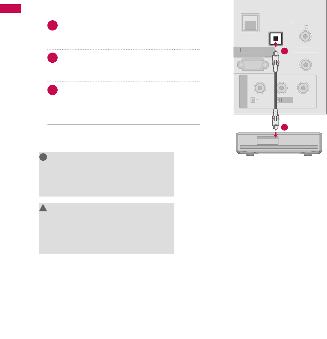
42
EXTERNAL EQUIPMENT SETUP
EXTERNAL EQUIPMENT SETUP
Send the TV’s audio to external audio equipment via the Audio Output port.
L R
S-VIDEO VIDEO
OUTPUT
SWITCH
L
R
S
-VIDE
O
VIDE
O
OUTPUT
S
WITC
H
ὤ㨴㥄
REMOTE
CONTROL OUT
OPTICAL
DIGITAL
AUDIO OUT
AV IN 1
AUDIO VIDEO
MONO
/
UPDATE
RESET
LAN
(SERVICE ONLY)
COMPONENT IN
VIDEO AUDIO
HDMI/DVI IN
2
1(DVI)
RJP
INTERFACE
SPEAKER OUT
8
RGB(PC) AUDIO
(RGB/DVI)
RGB IN
RS-232C IN
(SERVICE ONLY)
TV-LINK
CFG
GAME
CONTROL
REMOTE
CONTROL OUT
OPTICAL
DIGITAL
AUDIO OUT
AV IN 1
AUDIO VIDEO
MONO
/
UPDATE
RESET
LAN
(SERVICE ONLY)
COMPONENT IN
VIDEO AUDIO
RJP
INTERFACE
SPEAKER OUT
8
RGB(PC) AUDIO
(RGB/DVI)
RGB IN
RS-232C IN
(SERVICE ONLY)
TV-LINK
CFG
GAME
CONTROL
REMOT
E
C
ONTROL OU
T
O
PTI
C
A
L
D
I
G
ITAL
AUDI
O
O
U
T
AV IN 1
A
U
DI
O
VIDE
O
MONO
MONO
/
UPDATE
R
E
S
E
T
LAN
(
SERVICE ONLY)
CO
MP
O
NENT I
N
VIDE
O
AUDIO
R
J
P
INTERFA
CE
S
PEAKER
OU
T
8
R
G
B(P
C)
AUDIO
(RGB/DVI)
R
G
B IN
RS-232C IN
N
(SERVICE ONLY)
Y)
T
V-LIN
K
C
F
G
G
AM
E
CO
NTR
O
L
HDMI/DVI IN
2
1(DVI)
HDMI-DTV OUTPUT
1
REMOTE
CONTROL OUT
AV IN 1
AUDIO VIDEO
MONO
/
UPDA
TE
RESET
LAN
(SERVICE ONLY)
COMPONENT IN
VIDEO AUDIO
HDMI/DVI IN
2
1(DVI)
RJP
INTERFACE
SPEAKER OUT
8
RGB(PC) AUDIO
(RGB/DVI)
RGB IN
RS-232C IN
(SERVICE ONLY)
TV-LINK
CFG
GAME
CONTROL
R
EM
O
T
E
CO
NTR
O
L
OUT
AV IN
1
AUDI
O
VIDE
O
MONO
MONO
/
UPDATE
R
E
S
E
T
L
AN
(S
ERVI
C
E
O
NLY)
CO
MP
O
NENT I
N
VIDEO A
U
DI
O
HDMI
/
DVI IN
2
1(DVI
)
RJP
INTERFA
C
E
S
PEAKER
OU
T
8
RG
B
(
P
C)
A
UDIO
(RGB/DVI)
R
G
B I
N
RS-232C IN
N
(SERVICE ONLY)
Y)
T
V-LIN
K
CF
G
G
AME
CO
NTR
OL
OPTICAL
DIGITAL
AUDIO OUT
1
2
REMOTE
CONTROL OUT
OPTICAL
DIGITAL
AUDIO OUT
AV IN 1
AUDIO VIDEO
MONO
/
UPDATE
RESET
LAN
(SERVICE ONLY)
COMPONENT IN
VIDEO AUDIO
RJP
INTERFACE
SPEAKER OUT
8
RS-232C IN
(SERVICE ONLY)
TV-LINK
CFG
GAME
CONTROL
R
EM
O
T
E
CO
NTR
O
L
O
U
T
O
PTICA
L
D
I
G
ITAL
AUDIO OU
T
AV IN
1
A
U
DI
O
VIDE
O
MONO
MONO
/
UPDATE
R
E
S
E
T
LA
N
(
SERVICE ONLY
)
CO
MP
O
NENT I
N
VIDE
O
AUDI
O
R
JP
INTERFA
CE
S
PEAKER
OUT
8
RS-232C IN
N
(SERVICE ONLY)Y)
TV
-L
INK
C
F
G
G
AME
C
O
NTR
OL
HDMI/DVI IN
2
1(DVI)
RGB(PC) AUDIO
(RGB/DVI)
RGB IN
L R
DVI-DTV OUTPUT LR
1
2
REMOTE
CONTROL OUT
OPTICAL
DIGITAL
AUDIO OUT
UPDATE
RESET
LAN
(SERVICE ONLY)
COMPONENT IN
VIDEO AUDIO
HDMI/DVI IN
2
1(DVI)
RJP
INTERFACE
SPEAKER OUT
8
RGB(PC) AUDIO
(RGB/DVI)
RGB IN
RS-232C IN
(SERVICE ONLY)
TV-LINK
CFG
GAME
CONTROL
R
EMOT
E
CO
NTR
O
L
O
U
T
O
PTICA
L
D
IGITA
L
A
U
DI
O
OUT
UPDATE
RE
S
E
T
LA
N
(SERVICE ONLY
)
C
OMPONENT I
N
VIDEO AUDI
O
H
DMI
/
DVI IN
2
1(DVI)
RJP
I
NTERFA
C
E
S
PEAKER
OU
T
8
RGB(PC
)
AUDI
O
(RGB/DVI)
RG
B IN
RS-232C IN
N
(SERVICE ONLY)
Y)
TV
-L
INK
C
F
G
G
AME
C
O
NTR
OL
AV IN 1
AUDIO VIDEO
MONO
/
L
R
S-VIDEO
VIDEO
OUTPUT
SWITCH
ANT IN
ANT OUT
1
HDMI/DVI IN
2
1(DVI)
REMOTE
CONTROL OUT
OPTICAL
DIGITAL
AUDIO OUT
AV IN 1
AUDIO VIDEO
MONO
/
UPDATE
RESET
LAN
(SERVICE ONLY)
COMPONENT IN
VIDEO AUDIO
RJP
INTERFACE
SPEAKER OUT
8
RS-232C IN
(SERVICE ONLY)
TV-LINK
CFG
GAME
CONTROL
H
DMI
/
DVI IN
2
1
(
DVI
)
R
EM
O
T
E
CO
NTR
O
L
O
U
T
O
PTI
C
A
L
D
I
G
ITA
L
AUDI
O
O
U
T
AV IN
1
A
U
DI
O
VIDE
O
MONO
MONO
/
UPDATE
R
E
S
E
T
LAN
(
SERVICE ONLY
)
CO
MP
O
NENT I
N
VIDE
O
AUDI
O
RJ
P
I
NTERFA
C
E
S
PEAKER
O
UT
8
RS-232C IN
N
(SERVICE ONLY)
Y)
TV
-L
INK
C
F
G
G
AME
CO
NTR
OL
RGB(PC) AUDIO
(RGB/DVI)
RGB IN
AUDIO
RGB OUTPUT
2
1
ὤ㨴㥄
AV IN 2
L/MONO
R
AUDIO
VIDEO
USB IN
L R
VIDEO
1
Camcorder
Video Game Set
ANT IN
ANT OUT
ANTENNA IN M.P.I.
2
1
Wall Jack
Antenna
REMOTE
CONTROL OUT
OPTICAL
DIGITAL
AUDIO OUT
AV IN 1
AUDIO VIDEO
MONO
/
UPDATE
RESET
LAN
(SERVICE ONLY)
HDMI/DVI IN
2
1(DVI)
RJP
INTERFACE
SPEAKER OUT
8
RGB(PC) AUDIO
(RGB/DVI)
RGB IN
RS-232C IN
(SERVICE ONLY)
TV-LINK
CFG
GAME
CONTROL
R
EM
O
T
E
CO
NTR
O
L
OUT
O
PTICA
L
D
IGITAL
A
U
DI
O
OUT
AV IN
1
AUDIO VIDEO
MONO
MONO
/
U
PDAT
E
R
E
S
E
T
LA
N
(SERVICE ONLY
)
HDMI/DVI IN
2
1(DVI
)
RJP
INTERFA
CE
SPEAKER OU
T
8
RGB
(
PC
)
A
U
DI
O
(RGB/DVI)
RG
B IN
RS-232C INN
(SERVICE ONLY)
Y)
T
V-LIN
K
CF
G
G
AME
CO
NTR
OL
COMPONENT IN
VIDEO AUDIO
Y L RPBPR
12
NOTE
G When connecting with external audio
equipment, such as amplifiers or speakers, you
can turn the TV speakers off in the menu.
(G p. 88)
!
?
!
?
! !
CAUTION
G Do not look into the optical output port.
Looking at the laser beam may damage your
vision.
G Audio with ACP(Audio Copy Protection)
function my block digital audio output.
!
?
!
?
! !
AUDIO OUT CONNECTION
1. How to connect
1 Connect one end of the optical cable to the TV’s
OPTICAL DIGITAL AUDIO OUT.
2 Connect the other end of the optical cable to the
digital audio input on the audio equipment.
3 Set the “TV Speaker option - Off” in the AUDIO menu.
(G p. 88). See the external audio equipment instruc-
tion manual for operation.
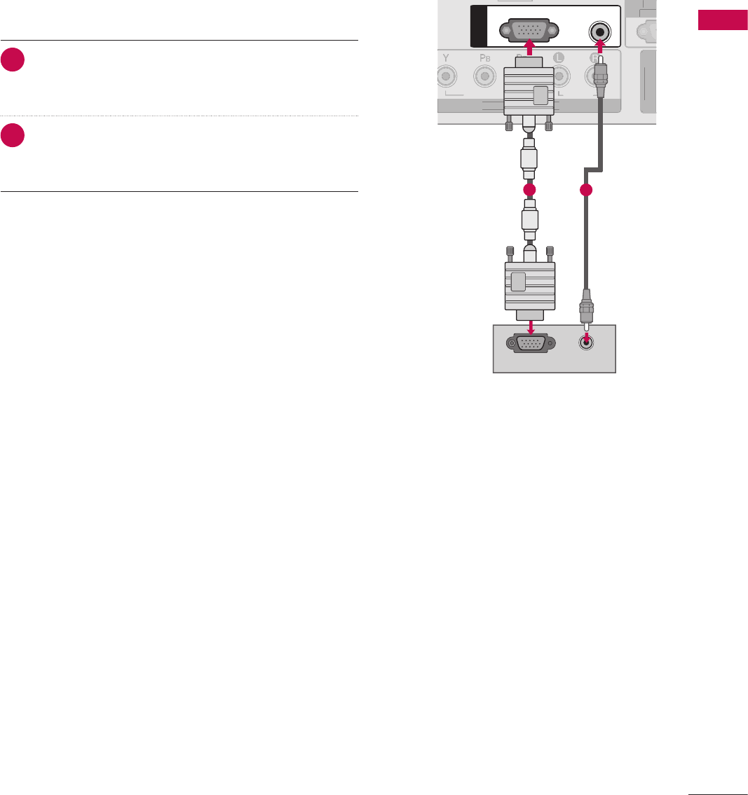
43
EXTERNAL EQUIPMENT SETUP
L R
S-VIDEO VIDEO
OUTPUT
SWITCH
L
R
S
-VIDE
O
VIDE
O
OUTPUT
S
WITC
H
ὤ㨴㥄
REMOTE
CONTROL OUT
OPTICAL
DIGITAL
AUDIO OUT
AV IN 1
AUDIO VIDEO
MONO
/
UPDATE
RESET
LAN
(SERVICE ONLY)
COMPONENT IN
VIDEO AUDIO
HDMI/DVI IN
2
1(DVI)
RJP
INTERFACE
SPEAKER OUT
8
RGB(PC) AUDIO
(RGB/DVI)
RGB IN
RS-232C IN
(SERVICE ONLY)
TV-LINK
CFG
GAME
CONTROL
REMOTE
CONTROL OUT
OPTICAL
DIGITAL
AUDIO OUT
AV IN 1
AUDIO VIDEO
MONO
/
UPDATE
RESET
LAN
(SERVICE ONLY)
COMPONENT IN
VIDEO AUDIO
RJP
INTERFACE
SPEAKER OUT
8
RGB(PC) AUDIO
(RGB/DVI)
RGB IN
RS-232C IN
(SERVICE ONLY)
TV-LINK
CFG
GAME
CONTROL
REMOT
E
C
ONTROL OU
T
O
PTI
C
A
L
D
I
G
ITAL
AUDI
O
O
U
T
AV IN 1
A
U
DI
O
VIDE
O
MONO
MONO
/
UPDATE
R
E
S
E
T
LAN
(
SERVICE ONLY)
CO
MP
O
NENT I
N
VIDE
O
AUDIO
R
J
P
INTERFA
CE
S
PEAKER
OU
T
8
R
G
B(P
C)
AUDIO
(RGB/DVI)
R
G
B IN
RS-232C INN
(SERVICE ONLY)
Y)
T
V-LIN
K
C
F
G
G
AM
E
CO
NTR
O
L
HDMI/DVI IN
2
1(DVI)
HDMI-DTV OUTPUT
1
REMOTE
CONTROL OUT
AV IN 1
AUDIO VIDEO
MONO
/
UPDATE
RESET
LAN
(SERVICE ONLY)
COMPONENT IN
VIDEO AUDIO
HDMI/DVI IN
2
1(DVI)
RJP
INTERFACE
SPEAKER OUT
8
RGB(PC) AUDIO
(RGB/DVI)
RGB IN
RS-232C IN
(SERVICE ONLY)
TV-LINK
CFG
GAME
CONTROL
R
EM
O
T
E
CO
NTR
O
L
OUT
AV IN
1
AUDI
O
VIDE
O
MONO
MONO
/
UPDATE
R
E
S
E
T
L
AN
(S
ERVI
C
E
O
NLY)
CO
MP
O
NENT I
N
VIDEO A
U
DI
O
HDMI
/
DVI IN
2
1(DVI
)
RJP
INTERFA
C
E
S
PEAKER
OU
T
8
RG
B
(
P
C)
A
UDIO
(RGB/DVI)
R
G
B I
N
RS-232C IN
N
(SERVICE ONLY)
Y)
T
V-LIN
K
CF
G
G
AME
CO
NTR
OL
OPTICAL
DIGITAL
AUDIO OUT
1
2
REMOTE
CONTROL OUT
OPTICAL
DIGITAL
AUDIO OUT
AV IN 1
AUDIO VIDEO
MONO
/
UPDATE
RESET
LAN
(SERVICE ONLY)
COMPONENT IN
VIDEO AUDIO
RJP
INTERFACE
SPEAKER OUT
8
RS-232C IN
(SERVICE ONLY)
TV-LINK
CFG
GAME
CONTROL
R
EM
O
T
E
CO
NTR
O
L
O
U
T
O
PTICA
L
D
I
G
ITAL
AUDIO OU
T
AV IN
1
A
U
DI
O
VIDE
O
MONO
MONO
/
UPDATE
R
E
S
E
T
LA
N
(
SERVICE ONLY
)
CO
MP
O
NENT I
N
VIDE
O
AUDI
O
R
JP
INTERFA
CE
S
PEAKER
OUT
8
RS-232C INN
(SERVICE ONLY)
Y)
TV
-L
INK
C
F
G
G
AME
C
O
NTR
OL
HDMI/DVI IN
2
1(DVI)
RGB(PC) AUDIO
(RGB/DVI)
RGB IN
L R
DVI-DTV OUTPUT LR
1
2
REMOTE
CONTROL OUT
OPTICAL
DIGITAL
AUDIO OUT
UPDATE
RESET
LAN
(SERVICE ONLY)
COMPONENT IN
VIDEO AUDIO
HDMI/DVI IN
2
1(DVI)
RJP
INTERFACE
SPEAKER OUT
8
RGB(PC) AUDIO
(RGB/DVI)
RGB IN
RS-232C IN
(SERVICE ONLY)
TV-LINK
CFG
GAME
CONTROL
R
EMOT
E
CO
NTR
O
L
O
U
T
O
PTICA
L
D
IGITA
L
A
U
DI
O
OUT
UPDATE
RE
S
E
T
LA
N
(SERVICE ONLY
)
C
OMPONENT I
N
VIDEO AUDI
O
H
DMI
/
DVI IN
2
1(DVI)
RJP
I
NTERFA
C
E
S
PEAKER
OU
T
8
RGB(PC
)
AUDI
O
(RGB/DVI)
RG
B IN
RS-232C IN
N
(SERVICE ONLY)
Y)
TV
-L
INK
C
F
G
G
AME
C
O
NTR
OL
AV IN 1
AUDIO VIDEO
MONO
/
L
R
S-VIDEO
VIDEO
OUTPUT
SWITCH
ANT IN
ANT OUT
1
HDMI/DVI IN
2
1(DVI)
REMOTE
CONTROL OUT
OPTICAL
DIGITAL
AUDIO OUT
AV IN 1
AUDIO VIDEO
MONO
/
UPDATE
RESET
LAN
(SERVICE ONLY)
COMPONENT IN
VIDEO AUDIO
RJP
INTERFACE
SPEAKER OUT
8
RS-232C IN
(SER
VICE ONLY)
TV-LINK
CFG
GAME
CONTROL
H
DMI
/
DVI IN
2
1
(
DVI
)
R
EM
O
T
E
CO
NTR
O
L
O
U
T
O
PTI
C
A
L
D
I
G
ITA
L
AUDI
O
O
U
T
AV IN
1
A
U
DI
O
VIDE
O
MONO
MONO
/
UPDATE
R
E
S
E
T
LAN
(
SERVICE ONLY
)
CO
MP
O
NENT I
N
VIDE
O
AUDI
O
RJ
P
I
NTERFA
C
E
S
PEAKER
O
UT
8
RS-232C IN
N
(SERVICE ONLY)
Y)
TV
-L
INK
C
F
G
G
AME
CO
NTR
OL
RGB(PC) AUDIO
(RGB/DVI)
RGB IN
AUDIO
RGB OUTPUT
2
1
ὤ㨴㥄
AV IN 2
L/MONO
R
AUDIO
VIDEO
USB IN
L R
VIDEO
1
Camcorder
Video Game Set
ANT IN
ANT OUT
ANTENNA IN M.P.I.
2
1
Wall Jack
Antenna
REMOTE
CONTROL OUT
OPTICAL
DIGITAL
AUDIO OUT
AV IN 1
AUDIO VIDEO
MONO
/
UPDATE
RESET
LAN
(SERVICE ONLY)
HDMI/DVI IN
2
1(DVI)
RJP
INTERFACE
SPEAKER OUT
8
RGB(PC) AUDIO
(RGB/DVI)
RGB IN
RS-232C IN
(SERVICE ONLY)
TV-LINK
CFG
GAME
CONTROL
R
EM
O
T
E
CO
NTR
O
L
OUT
O
PTICA
L
D
IGITAL
A
U
DI
O
OUT
AV IN
1
AUDIO VIDEO
MONO
MONO
/
U
PDAT
E
R
E
S
E
T
LA
N
(SERVICE ONLY
)
HDMI/DVI IN
2
1(DVI
)
RJP
INTERFA
CE
SPEAKER OU
T
8
RGB
(
PC
)
A
U
DI
O
(RGB/DVI)
RG
B IN
RS-232C INN
(SERVICE ONLY)
Y)
T
V-LIN
K
CF
G
G
AME
CO
NTR
OL
COMPONENT IN
VIDEO AUDIO
Y L RP
B
P
R
12
PC SETUP
This TV provides Plug and Play capability, meaning that the PC adjusts automatically to the TV's settings.
VGA (D-Sub 15 pin) Connection
1. How to connect
1 Connect the VGA output of the PC to the RGB (PC)
jack on the TV.
2 Connect the PC audio output to the AUDIO (RGB/
DVI) jack on the TV.
2. How to use
V Turn on the PC and the TV.
V Select the RGB-PC input source on the TV using the
INPUT button on the remote control.
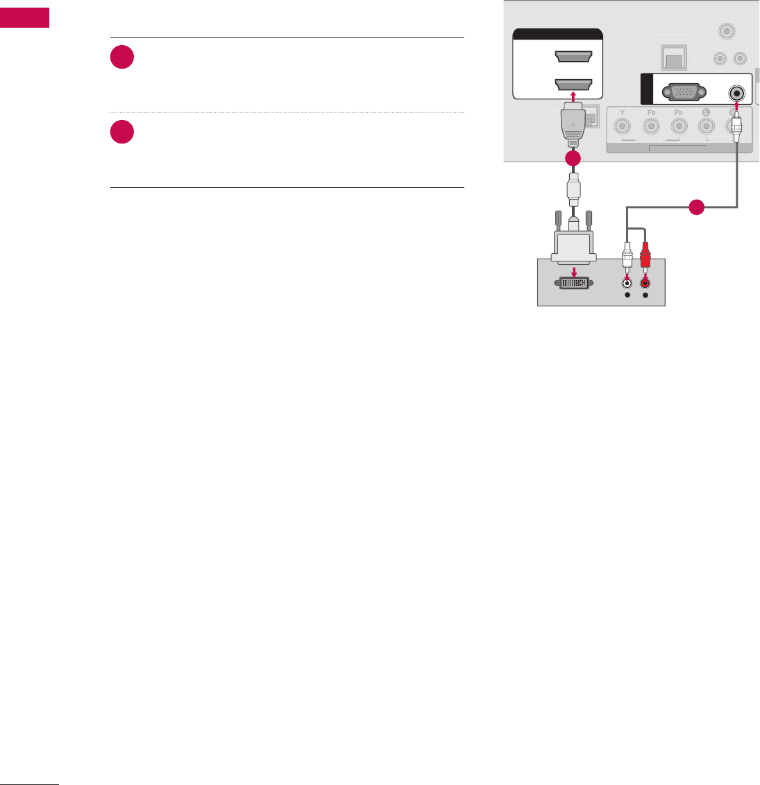
44
EXTERNAL EQUIPMENT SETUP
EXTERNAL EQUIPMENT SETUP
L R
S-VIDEO VIDEO
OUTPUT
SWITCH
L
R
S
-VIDE
O
VIDE
O
OUTPUT
S
WITC
H
ὤ㨴㥄
REMOTE
CONTROL OUT
OPTICAL
DIGITAL
AUDIO OUT
AV IN 1
AUDIO VIDEO
MONO
/
UPDATE
RESET
LAN
(SERVICE ONLY)
COMPONENT IN
VIDEO AUDIO
HDMI/DVI IN
2
1(DVI)
RJP
INTERFACE
SPEAKER OUT
8
RGB(PC) AUDIO
(RGB/DVI)
RGB IN
RS-232C IN
(SERVICE ONLY)
TV-LINK
CFG
GAME
CONTROL
REMOTE
CONTROL OUT
OPTICAL
DIGITAL
AUDIO OUT
AV IN 1
AUDIO VIDEO
MONO
/
UPDATE
RESET
LAN
(SERVICE ONLY)
COMPONENT IN
VIDEO AUDIO
RJP
INTERFACE
SPEAKER OUT
8
RGB(PC) AUDIO
(RGB/DVI)
RGB IN
RS-232C IN
(SERVICE ONLY)
TV-LINK
CFG
GAME
CONTROL
REMOT
E
C
ONTROL OU
T
O
PTI
C
A
L
D
I
G
ITAL
AUDI
O
O
U
T
AV IN 1
A
U
DI
O
VIDE
O
MONO
MONO
/
UPDATE
R
E
S
E
T
LAN
(
SERVICE ONLY)
CO
MP
O
NENT I
N
VIDE
O
AUDIO
R
J
P
INTERFA
CE
S
PEAKER
OU
T
8
R
G
B(P
C)
AUDIO
(RGB/DVI)
R
G
B IN
RS-232C IN
N
(SERVICE ONLY)
Y)
T
V-LIN
K
C
F
G
G
AM
E
CO
NTR
O
L
HDMI/DVI IN
2
1(DVI)
HDMI-DTV OUTPUT
1
REMOTE
CONTROL OUT
AV IN 1
AUDIO VIDEO
MONO
/
UPDATE
RESET
LAN
(SERVICE ONLY)
COMPONENT IN
VIDEO AUDIO
HDMI/DVI IN
2
1(DVI)
RJP
INTERFACE
SPEAKER OUT
8
RGB(PC) AUDIO
(RGB/DVI)
RGB IN
RS-232C IN
(SERVICE ONLY)
TV-LINK
CFG
GAME
CONTROL
R
EM
O
T
E
CO
NTR
O
L
OUT
AV IN
1
AUDI
O
VIDE
O
MONO
MONO
/
UPDATE
R
E
S
E
T
L
AN
(S
ERVI
C
E
O
NLY)
CO
MP
O
NENT I
N
VIDEO A
U
DI
O
HDMI
/
DVI IN
2
1(DVI
)
RJP
INTERFA
C
E
S
PEAKER
OU
T
8
RG
B
(
P
C)
A
UDIO
(RGB/DVI)
R
G
B I
N
RS-232C IN
N
(SERVICE ONLY)
Y)
T
V-LIN
K
CF
G
G
AME
CO
NTR
OL
OPTICAL
DIGITAL
AUDIO OUT
1
2
REMOTE
CONTROL OUT
OPTICAL
DIGITAL
AUDIO OUT
AV IN 1
AUDIO VIDEO
MONO
/
UPDATE
RESET
LAN
(SERVICE ONLY)
COMPONENT IN
VIDEO AUDIO
RJP
INTERFACE
SPEAKER OUT
8
RS-232C IN
(SERVICE ONLY)
TV-LINK
CFG
GAME
CONTROL
R
EM
O
T
E
CO
NTR
O
L
O
U
T
O
PTICA
L
D
I
G
ITAL
AUDIO OU
T
AV IN
1
A
U
DI
O
VIDE
O
MONO
MONO
/
UPDATE
R
E
S
E
T
LA
N
(
SERVICE ONLY
)
CO
MP
O
NENT I
N
VIDE
O
AUDI
O
R
JP
INTERFA
CE
S
PEAKER
OUT
8
RS-232C IN
N
(SERVICE ONLY)
Y)
TV
-L
INK
C
F
G
G
AME
C
O
NTR
OL
HDMI/DVI IN
2
1(DVI)
RGB(PC) AUDIO
(RGB/DVI)
RGB IN
L R
DVI-DTV OUTPUT LR
1
2
REMOTE
CONTROL OUT
OPTICAL
DIGITAL
AUDIO OUT
UPDATE
RESET
LAN
(SERVICE ONLY)
COMPONENT IN
VIDEO AUDIO
HDMI/DVI IN
2
1(DVI)
RJP
INTERFACE
SPEAKER OUT
8
RGB(PC) AUDIO
(RGB/DVI)
RGB IN
RS-232C IN
(SERVICE ONLY)
TV-LINK
CFG
GAME
CONTROL
R
EMOT
E
CO
NTR
O
L
O
U
T
O
PTICA
L
D
IGITA
L
A
U
DI
O
OUT
UPDATE
RE
S
E
T
LA
N
(SERVICE ONLY
)
C
OMPONENT I
N
VIDEO AUDI
O
H
DMI
/
DVI IN
2
1(DVI)
RJP
I
NTERFA
C
E
S
PEAKER
OU
T
8
RGB(PC
)
AUDI
O
(RGB/DVI)
RG
B IN
RS-232C IN
N
(SERVICE ONLY)
Y)
TV
-L
INK
C
F
G
G
AME
C
O
NTR
OL
AV IN 1
AUDIO VIDEO
MONO
/
L
R
S-VIDEO
VIDEO
OUTPUT
SWITCH
ANT IN
ANT OUT
1
HDMI/DVI IN
2
1(DVI)
REMOTE
CONTROL OUT
OPTICAL
DIGITAL
AUDIO OUT
AV IN 1
AUDIO VIDEO
MONO
/
UPDATE
RESET
LAN
(SERVICE ONLY)
COMPONENT IN
VIDEO AUDIO
RJP
INTERFACE
SPEAKER OUT
8
RS-232C IN
(SERVICE ONLY)
TV-LINK
CFG
GAME
CONTROL
H
DMI
/
DVI IN
2
1
(
DVI
)
R
EM
O
T
E
CO
NTR
O
L
O
U
T
O
PTI
C
A
L
D
I
G
ITA
L
AUDI
O
O
U
T
AV IN
1
A
U
DI
O
VIDE
O
MONO
MONO
/
UPDATE
R
E
S
E
T
LAN
(
SERVICE ONLY
)
CO
MP
O
NENT I
N
VIDE
O
AUDI
O
RJ
P
I
NTERFA
C
E
S
PEAKER
O
UT
8
RS-232C IN
N
(SERVICE ONLY)
Y)
TV
-L
INK
C
F
G
G
AME
CO
NTR
OL
RGB(PC) AUDIO
(RGB/DVI)
RGB IN
AUDIO
RGB OUTPUT
2
1
ὤ㨴㥄
AV IN 2
L/MONO
R
AUDIO
VIDEO
USB IN
L R
VIDEO
1
Camcorder
Video Game Set
ANT IN
ANT OUT
ANTENNA IN M.P.I.
2
1
Wall Jack
Antenna
REMOTE
CONTROL OUT
OPTICAL
DIGITAL
AUDIO OUT
AV IN 1
AUDIO VIDEO
MONO
/
UPDATE
RESET
LAN
(SERVICE ONLY)
HDMI/DVI IN
2
1(DVI)
RJP
INTERFACE
SPEAKER OUT
8
RGB(PC) AUDIO
(RGB/DVI)
RGB IN
RS-232C IN
(SERVICE ONLY)
TV-LINK
CFG
GAME
CONTROL
R
EM
O
T
E
CO
NTR
O
L
OUT
O
PTICA
L
D
IGITAL
A
U
DI
O
OUT
AV IN
1
AUDIO VIDEO
MONO
MONO
/
U
PDAT
E
R
E
S
E
T
LA
N
(SERVICE ONLY
)
HDMI/DVI IN
2
1(DVI
)
RJP
INTERFA
CE
SPEAKER OU
T
8
RGB
(
PC
)
A
U
DI
O
(RGB/DVI)
RG
B IN
RS-232C IN
N
(SERVICE ONLY)
Y)
T
V-LIN
K
CF
G
G
AME
CO
NTR
OL
COMPONENT IN
VIDEO AUDIO
Y L RP
B
P
R
12
DVI to HDMI Connection
1. How to connect
1 Connect the DVI output of the PC to the HDMI/DVI
IN 1 (DVI) jack on the TV.
2 Connect the PC audio output to the AUDIO (RGB/
DVI) jack on the TV.
2. How to use
V Turn on the PC and the TV.
V Select the HDMI1 input source on the TV using the
INPUT button on the remote control.
45
EXTERNAL EQUIPMENT SETUP
Supported Display Specifications
NOTE
G To get the best picture quality, adjust the PC
graphics card to 1360x768
(32/37/42LG710H, 32LD650H, 32LD655H,
32LD660H, 32LD665H, 32LV555H) or
1920x1080 (37/42/47/55LD650H,
37/42LD655H, 37/42LD660H,
37/42LD665H, 37/42/47/55LV555H).
G Depending on the graphics card, DOS mode may
not work if a HDMI to DVI Cable is in use.
G In PC mode, there may be noise associated with
the resolution, vertical pattern, contrast or
brightness. If noise is present, change the PC
output to another resolution, change the refresh
rate to another rate or adjust the brightness and
contrast on the PICTURE menu until the picture is
clear.
When you use too long RGB-PC cable, there might
be a noise on the screen.
G Avoid keeping a fixed image on the screen for a
long period of time. The fixed image could become
permanently imprinted on the screen.
G The synchronization input form for Horizontal and
Vertical frequencies is separate.
G Depending on the graphics card, some resolution
settings may not allow the image to be
positioned on the screen properly.
!
?
!
?
! !
HDMI-PC
Resolution Horizontal
Frequency(kHz)
Vertical
Frequency(Hz)
720x400 31.469 70.08
800x600 35.156
37.879
56.25
60.31
1024x768 48.363 60.00
1280x768 47.776 59.87
1360x768 47.712 60.015
1280x1024 63.981 60.02
1920x1080 67.500 60.000
RGB-PC
Resolution Horizontal
Frequency(kHz)
Vertical
Frequency(Hz)
720x400 31.469 70.08
640x480 31.469
37.861
59.94
72.80
800x600 37.879
48.077
60.31
72.18
1024x768 48.363
56.476
60.00
70.06
1280x768
47.776
60.289
59.870
74.893
1360x768 47.712 60.015
1280x1024
63.981
79.976
60.020
75.025
1920x1080 66.587 59.934
Except 32/37/42LG710H,32LD65H,
32LD655H, 32LD660H,
32LD665H, 32LV555H
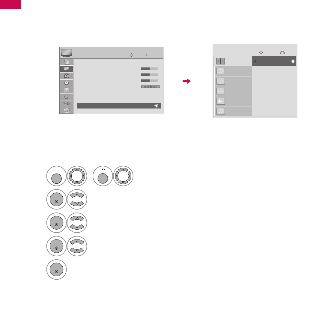
46
EXTERNAL EQUIPMENT SETUP
EXTERNAL EQUIPMENT SETUP
Screen Setup for PC mode
Selecting Resolution
When using RGB-PC input, change the resolution in the menus to match the PC’s.
The Position, Phase, and Size can also be adjusted.
1
MENU
or
Home
Select PICTURE.
2
ENTER
Select Screen (RGB-PC).
3
ENTER
Select Resolution.
4
ENTER
Select the desired resolution.
5
ENTER
ὤ㨴㥄
EnterMove
PICTURE
D
• Brightness 50
• Sharpness 50
• Color 50
• Tint 0 R G
• Advanced Control
• Picture Reset
Screen (RGB-PC)
SCREEN
ὤ㨴㥄
Move
ὤ㨴㥄
Prev.
Resolution 1024 x 768
Auto Config. 1280 x 768
Position 1360 x 768
Size
Phase
Reset
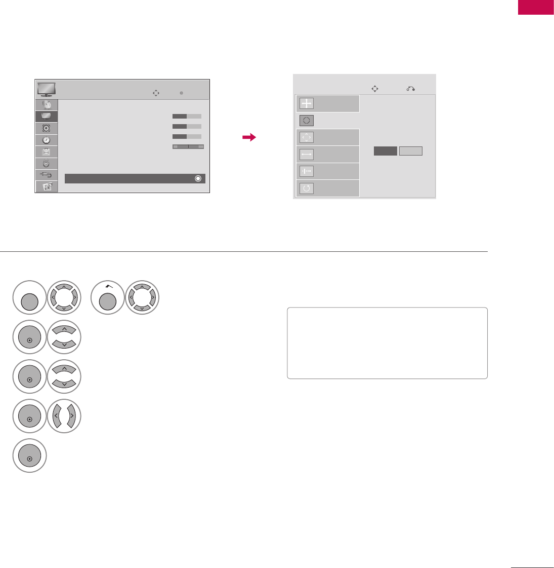
47
EXTERNAL EQUIPMENT SETUP
1
MENU
or
Home
Select PICTURE.
2
ENTER
Select Screen (RGB-PC).
3
ENTER
Select Auto config.
4
ENTER
Select Yes.
5
ENTER
Auto Configure
Automatically adjusts picture position and minimizes image instability. After adjustment, if the image is still
not correct, try using the manual settings or a different resolution or refresh rate on the PC.
• If the position of the image is still not
correct, try Auto adjustment again.
• If picture needs to be adjusted again after
Auto adjustment in RGB-PC, you can adjust
the Position, Size or Phase.
ὤ㨴㥄
EnterMove
PICTURE
D
• Brightness 50
• Sharpness 50
• Color 50
• Tint 0 R G
• Advanced Control
• Picture Reset
Screen (RGB-PC)
SCREEN
ὤ㨴㥄
Move
ὤ㨴㥄
Prev.
Resolution
To Set
Yes No
Auto Config.
Position
Size
Phase
Reset
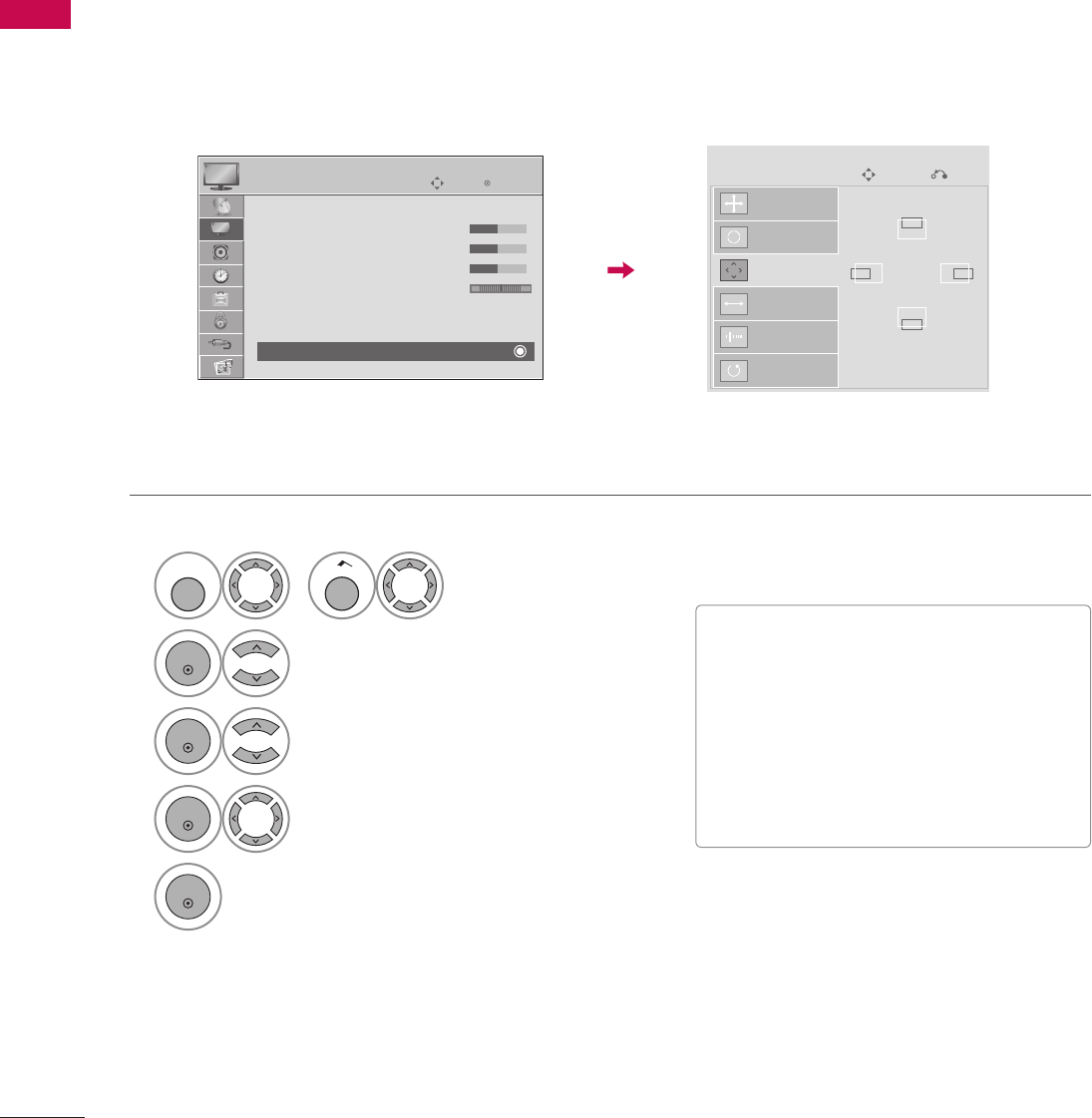
48
EXTERNAL EQUIPMENT SETUP
EXTERNAL EQUIPMENT SETUP
1
MENU
or
Home
Select PICTURE.
2
ENTER
Select Screen (RGB-PC).
3
ENTER
Select Position, Size, or Phase.
4
ENTER
Make appropriate adjustments.
5
ENTER
Adjustment for screen Position, Size, and Phase
If the picture is not clear after auto adjustment and especially if characters are still trembling, adjust the picture
phase manually.
This feature operates only in RGB-PC mode.
V Position: This function is to adjust picture
to left/right and up/down as you prefer.
V Size: This function is to minimize any vertical
bars or stripes visible on the screen
background. And the horizontal screen size
will also change.
V Phase: This function allows you to remove
any horizontal noise and clear or sharpen
the image of characters.
ὤ㨴㥄
EnterMove
PICTURE
D
• Brightness 50
• Sharpness 50
• Color 50
• Tint 0 R G
• Advanced Control
• Picture Reset
Screen (RGB-PC)
SCREEN
ὤ㨴㥄
Move
ὤ㨴㥄
Prev.
Resolution
D
Auto Config.
Position
F G
Size
E
Phase
Reset

49
EXTERNAL EQUIPMENT SETUP
1
MENU
or
Home
Select PICTURE.
2
ENTER
Select Screen (RGB-PC).
3
ENTER
Select Reset.
4
ENTER
SelecttYes.
5
ENTER
Screen Reset (Reset to original factory values)
Returns Position, Size, and Phase to the default factory settings.
This feature operates only in RGB-PC mode.
ὤ㨴㥄
EnterMove
PICTURE
D
• Brightness 50
• Sharpness 50
• Color 50
• Tint 0 R G
• Advanced Control
• Picture Reset
Screen (RGB-PC)
SCREEN
ὤ㨴㥄
Move
ὤ㨴㥄
Prev.
Resolution
To Set
Yes No
Auto Config.
Position
Size
Phase
Reset
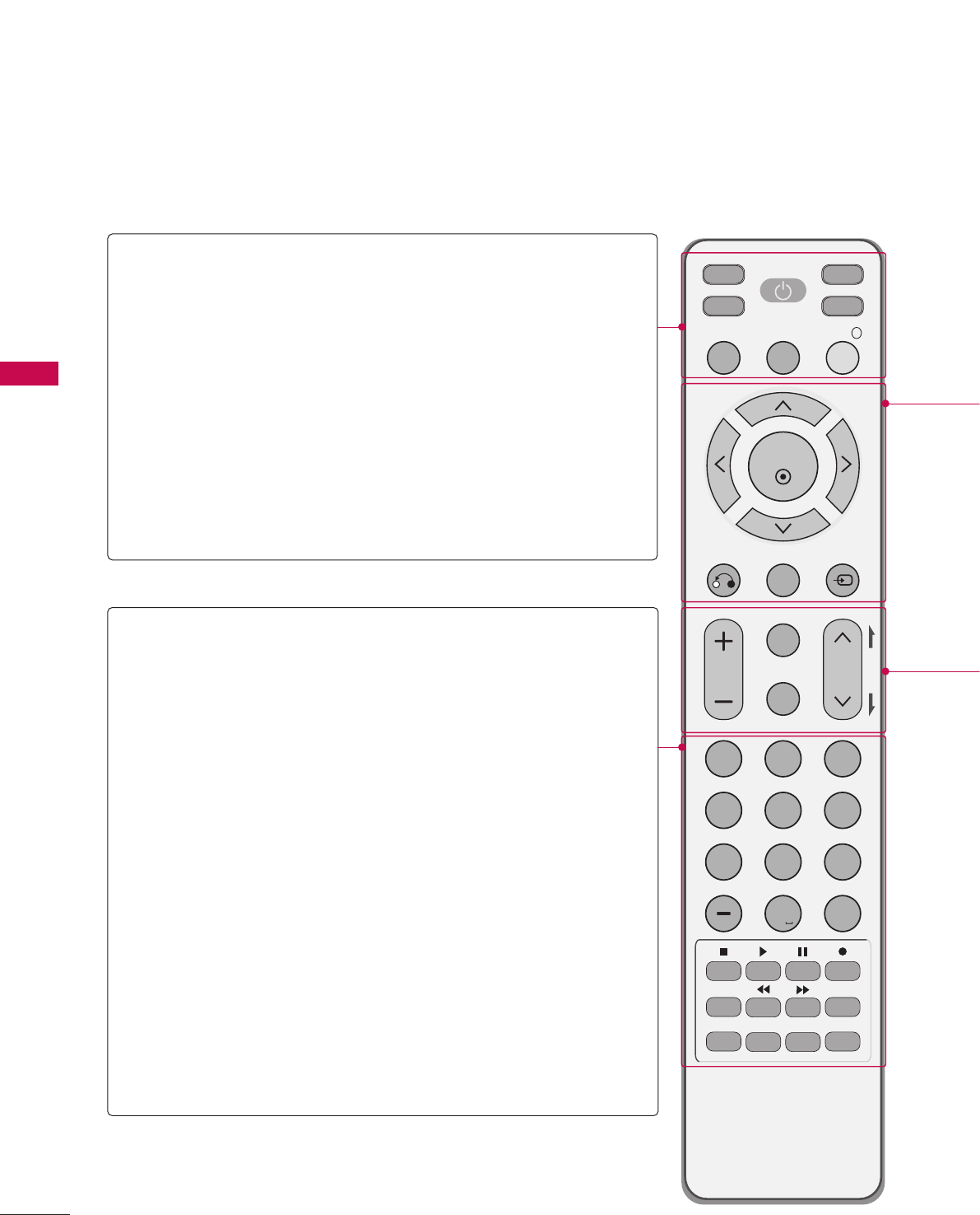
50
WATCHING TV / CHANNEL CONTROL
WATCHING TV / CHANNEL CONTROL
WATCHING TV / CHANNEL CONTROL
REFERENCE
POINT
MUTE
RETURN
CC
TV
POWER
GUIDE PORTAL
ENTER
VOL CH
1 2 3
4 5 6
7 8
0
9
FLASHBK
VCR
DVD
INPUT
MENU
INFO
i
STB
P
A
G
E
PIP SAP
PIP CH- PIP CH+
PIP SWAP
PIP INPUT
ALPHA/NUM
REMOVE
RATIO
TIMER
ABC DEF
GHI
WXYZ
TUVPQRS
MNOJKL
&@
.:/,
REMOTE CONTROL FUNCTIONS
When using the remote control, aim it at the remote control sensor on the TV.
POWER Turns your TV or any other programmed equipment on
or off, depending on mode.
TV/STB/DVD/
VCR
Selects the remote’s operating mode: TV, STB, DVD, or
VCR.
GUIDE Displays and removes the electronic channel guide.
This key works only in GEM or Flash environment.
PORTAL Displays and removes the hotel interactive menu.
This key works only in GEM or Flash environment.
INFO Displays information about the selected or current
events.
This key works only in GEM or Flash environment.
NUMBER
button
Selects channel numbers or other numbers required.
Also supports characters.
— (DASH) Selects a program number for multiple program channels
such as 2-1, 2-2, etc.
FLASH BK Tunes to the last channel or input viewed.
VCR/DVD/USB
control buttons
Controls video cassette recorders or DVD players or
USB.
PIP Toggles through picture-in-picture options.
RATIO Changes the aspect ratio. G p.73
TIMER Turns the TV off in a set amount of time. G p.100
SAP O Analog mode: Selects MTS sound (Mono, Stereo, or a
SAP). G p.90
O DTV mode: Changes the audio language.
PIP CH +/- Changes the PIP channel.
PIP SWAP Exchanges the main/sub images.
PIP INPUT Selects the connected input source for the sub-picture.
51
WATCHING TV / CHANNEL CONTROL
THUMBSTICK
(Up/Down/Left
Right/ENTER)
Navigates the on-screen menus and adjusts the system settings to your preference.
RETURN Clears all on-screen displays and returns to TV viewing from any menu.
MENU Displays the main menu.
INPUT Rotates through inputs.
Also switches the TV on from standby.
VOLUME UP
/DOWN
Adjusts the volume.
CC Selects a closed caption. G p.93
MUTE Switches the sound on or off. G p.53
CHANNEL
UP/DOWN
Selects available channels.
PAGE
UP/DOWN
Moves from one full set of screen information to the next one.
Installing Batteries
REFERENCE
POINT
MUTE
RETURN
CC
TV
POWER
GUIDE PORTAL
ENTER
VOL CH
1 2 3
4 5 6
7 8
0
9
FLASHBK
VCR
DVD
INPUT
MENU
INFO
i
STB
P
A
G
E
PIP SAP
PIP CH- PIP CH+
PIP SWAP
PIP INPUT
ALPHA/NUM
REMOVE
RATIO
TIMER
ABC DEF
GHI
WXYZ
TUVPQRS
MNOJKL
&@
.:/,
V Open the battery compartment cover on the back side and install the
batteries with the correct polarity (+with +,-with -).
V Install two 1.5V AAA batteries. Don’t mix old or used batteries
with new ones.
V Close cover.

52
WATCHING TV / CHANNEL CONTROL
WATCHING TV / CHANNEL CONTROL
NOTE
G If you intend to be away on vacation, disconnect the power plug from the wall power outlet.
!
?
!
?
! !
TURNING ON THE TV
1 First, connect the power cord correctly.
At this moment, the TV switches to standby mode.
V
In standby mode to turn TV on, press the
ὤ㨴㥄
button on the TV or press
the POWER button on the remote control.
2 Select the viewing source by using the INPUT button on the remote
control.
3 When finished using the TV, press the POWER button on the remote
control. The TV reverts to standby mode.

53
WATCHING TV / CHANNEL CONTROL
Adjust the volume to suit your personal preference.
CHANNEL SELECTION
VOLUME ADJUSTMENT
1 Press the CH(
ὤ㨴㥄
or
ὤ㨴㥄
) or NUMBER buttons to select a channel number.
1 Press the VOL (+ or -) button to adjust the volume.
2 If you want to switch the sound off, press the MUTE button.
3 You can cancel the Mute function by pressing the MUTE or VOL (+ or -)
button.
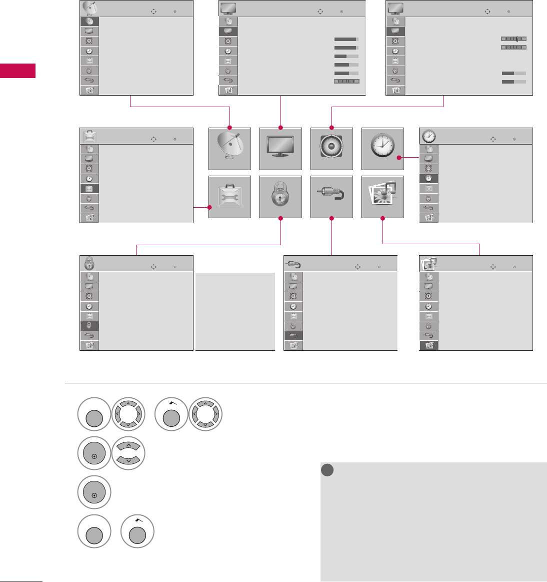
54
WATCHING TV / CHANNEL CONTROL
WATCHING TV / CHANNEL CONTROL
1
MENU
or
Home
Display each menu.
2
ENTER
Select a menu item.
3
ENTER
Accept the current selection.
4
MENU
or
Home
Return to TV viewing.
Your TV's OSD (On Screen Display) may differ slightly from that shown in this manual.
NOTE
G Infinite Sound: For 32/37/42/47/55LD650H,
32/37/42LD655H, 32/37/42LD660H,
32/37/42LD665H, 32/37/42/47/55LV555H
G Data Broadcasting: For 32/37/42LG710H,
32/37/42/47/55LD650H,
32/37/42LD655H
G Zone : For 32/37/42LD660H,
32/37/42LD665H, 32/37/42/47/55LV555H
!
?
!
?
! !
ON-SCREEN MENUS SELECTION
CHANNEL
OPTION
PICTURE
LOCK
AUDIO
INPUT
TIME
USB
EnterMove
PICTURE
Aspect Ratio : 16:9
Picture Mode : Standard
• BackLight 90
• Contrast 90
• Brightness 50
• Sharpness 30
• Color 60
• Tint 0 R G
E
EnterMove
AUDIO
Auto Volume : On
Clear Voice II : On
•L eve l 3 - +
Balance 0 L R
Sound Mode : Standard
• SRS TruSurround XT: Off
•Treble 50
•Bass 50
E
EnterMove
CHANNEL
Auto Tuning
Manual Tuning
Channel Edit
Channel Label
EnterMove
OPTION
Menu Language : English
Audio Language : English
Caption : Off
Set ID : 1
Demo Mode : Off
Data Broadcasting
Zone
For USA
EnterMove
LOCK
Lock System : Off
Set Password
Block Channel
Movie Rating
TV Rating-Children
TV Rating-General
Downloadable Rating
Input Block
For CANADA
Lock System : Off
Set Password
Block Channel
TV Rating-English
TV Rating-French
Downloadable Rating
Input Block
EnterMove
INPUT
TV
AV1
AV2
Component
RGB-PC
HDMI1
HDMI2
EnterMove
USB
Photo List
Music List
Extra Contents
Eject
EnterMove
TIME
Clock
Off Time : Off
On Time : Off
Sleep Timer : Off
Auto Off : On
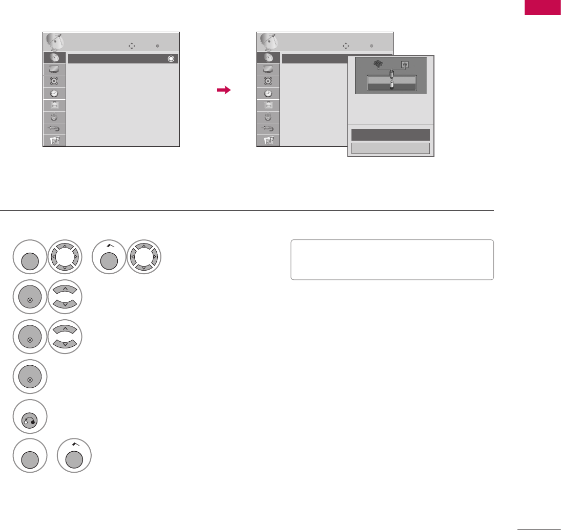
55
WATCHING TV / CHANNEL CONTROL
Auto Scan (Auto Tuning)
Automatically finds all channels available through antenna or cable inputs and stores them in memory on the
channel list.
Run Auto Tuning again after any Antenna/Cable connection changes.
CHANNEL SETUP
1
MENU
or
Home
Select CHANNEL.
2
ENTER
Select Auto Tuning.
3
ENTER
Select Yes.
4
ENTER
Run Auto tuning.
5
RETURN
Return to the previous menu.
MENU
or
Home
Return to TV viewing.
EnterMove
CHANNEL
Auto Tuning
Manual Tuning
Channel Edit
Channel Label
Check your antenna connection.
The previous channel
information will be updated
during Auto Tuning.
Yes
No
ὤ㨴㥄
EnterMove
CHANNEL
Auto Tuning
Manual Tuning
Channel Edit
Channel Label
V A password is required to gain access to
Auto Tuning menu if the Lock System is
turned on.
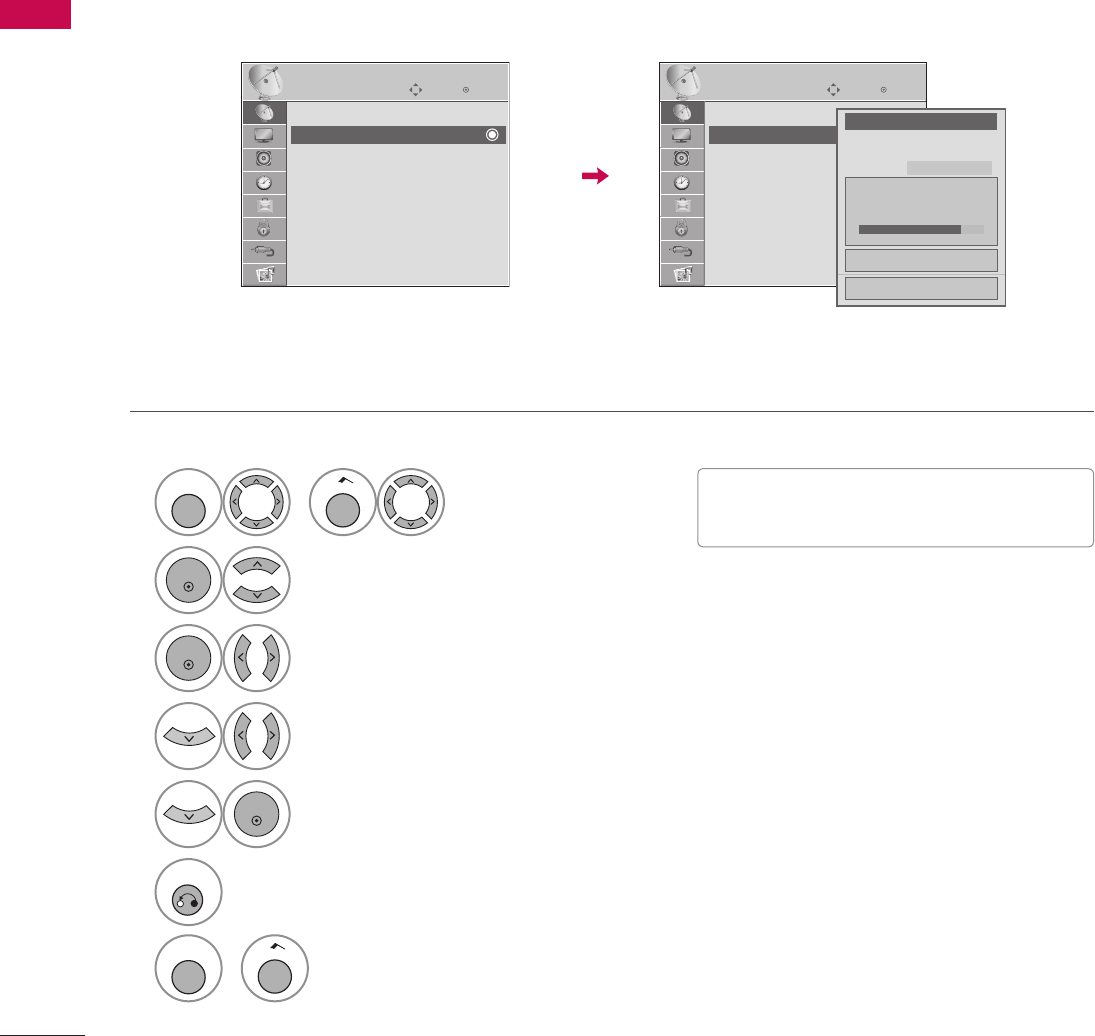
56
WATCHING TV / CHANNEL CONTROL
WATCHING TV / CHANNEL CONTROL
1
MENU
or
Home
Select CHANNEL.
2
ENTER
Select Manual Tuning.
3
ENTER
Select DIGITAL or ANALOG.
4
Select channel you want to add or delete.
5
ENTER
Select Add or Delete.
6
RETURN
Return to the previous menu.
MENU
or
Home
Return to TV viewing.
If selecting DIGITAL input signal, you can view the on-screen signal strength monitor to see the quality of the
signal being received.
Add/Delete Channel (Manual Tuning)
V A password is required to gain access to
Manual Tuning menu if the Lock System is
turned on.
EnterMove
CHANNEL
Auto Tuning
Manual Tuning
Channel Edit
Channel Label
F DIGITAL G
Select channel type and
RF-channel number.
Channel 2
DIGITAL 2-1
Bad Normal Good
Delete
No
ὤ㨴㥄
EnterMove
CHANNEL
Auto Tuning
Manual Tuning
Channel Edit
Channel Label
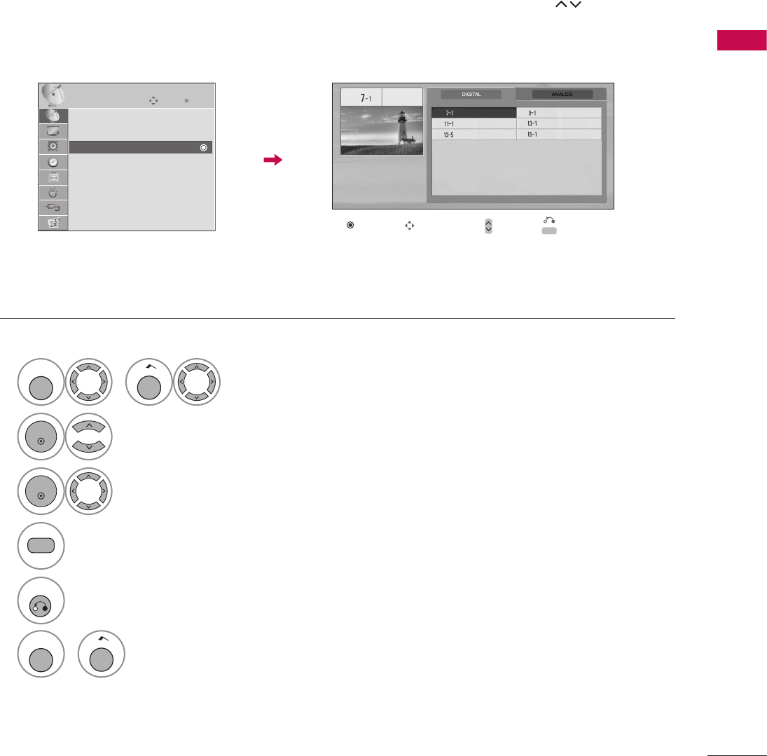
57
WATCHING TV / CHANNEL CONTROL
1
MENU
or
Home
Select CHANNEL.
2
ENTER
Select Channel Edit.
3
ENTER
Select a channel.
4
Select channel you want to add or delete.
5
RETURN
Return to the previous menu.
MENU
or
Home
Return to TV viewing.
The channels in the Channel Edit List are displayed in black and the channels deleted from the Channel Edit
List are displayed in blue.
When a channel number is deleted, it means that you will be unable to select it using CH
ὤ㨴㥄
ὤ㨴㥄
button during
TV viewing. If you wish to select the deleted channel, directly enter the channel number with the NUMBER but-
tons or select it in the Channel Edit menu.
Channel Editing
ὤ㨴㥄
Enter
Move
CHANNEL
Auto Tuning
Manual Tuning
Channel Edit
Channel Label
Ch. Change
ὤ㨴㥄
Navigation CH
ὤ㨴㥄
ὤ㨴㥄
Page Change
ὤ㨴㥄
Previous
Add/Delete
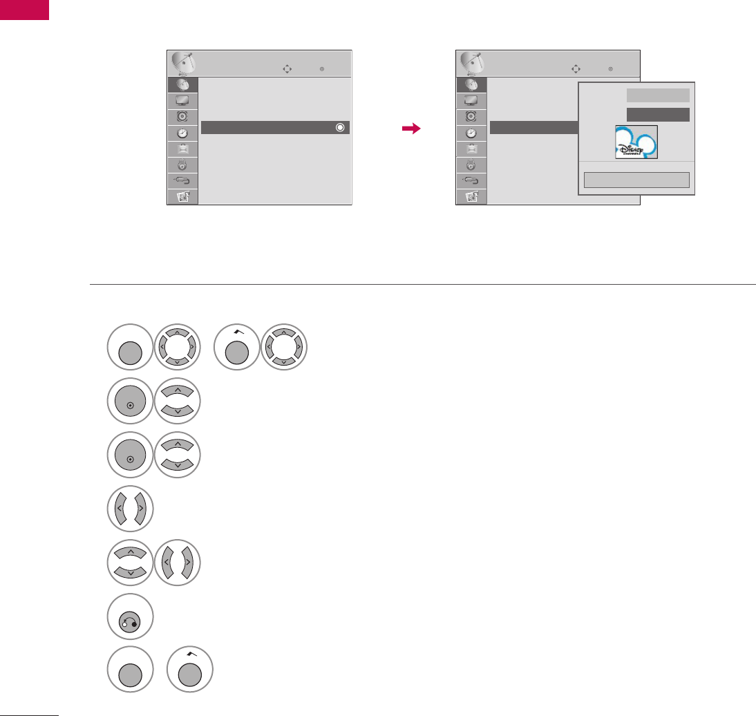
58
WATCHING TV / CHANNEL CONTROL
WATCHING TV / CHANNEL CONTROL
Choose preset labels for your channels.
If a channel label is provided on the signal from the broadcasting station, the TV displays a short name for a
channel even if you didn't preset a label for the channel.
CHANNEL LABEL
1
MENU
or
Home
Select CHANNEL.
2
ENTER
Select Channel Label.
3
ENTER
Select a channel.
4
Select a channel to set logo.
5
Select the appropriate logo for the channel.
6
RETURN
Return to the previous menu.
MENU
or
Home
Return to TV viewing.
EnterMove
CHANNEL
Auto Tuning
Manual Tuning
Channel Edit
Channel Label
Channel ANALOG 2-0
Logo F Disney G
Close
ὤ㨴㥄
EnterMove
CHANNEL
Auto Tuning
Manual Tuning
Channel Edit
Channel Label
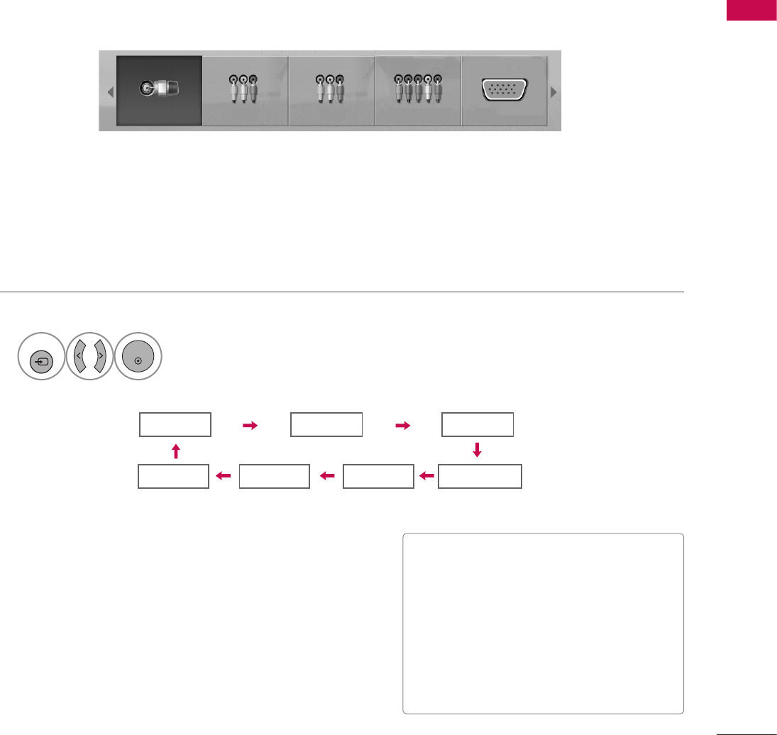
59
WATCHING TV / CHANNEL CONTROL
TV AV1 AV2
Component
HDMI1 RGB-PC
HDMI2
ὤ㨴㥄
ὤ㨴㥄
ὤ㨴㥄
ὤ㨴㥄
ὤ㨴㥄
ὤ㨴㥄
ὤ㨴㥄
INPUT LIST
1
INPUT
ENTER
Select the desired input source.
V TV: Select it to watch over-the-air, cable and
digital cable broadcasts.
V AV1-2: Select them to watch a VCR or other
external equipment.
V Component: Select them to watch DVD or a
Digital set-top box.
V RGB-PC: Select it to view PC input.
V HDMI1-2: Select them to watch high
definition devices.
TV AV1 AV2 Component RGB-PC
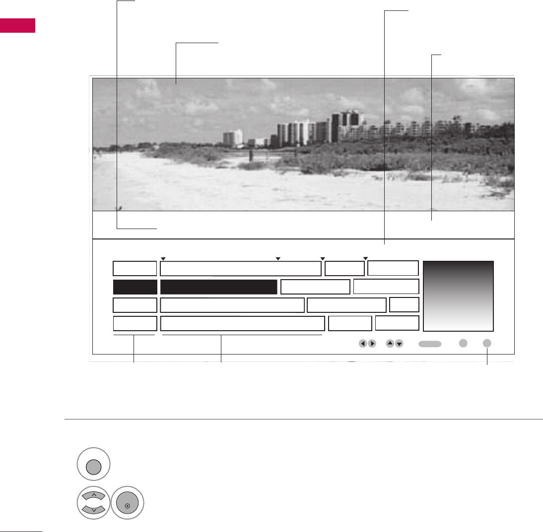
60
WATCHING TV / CHANNEL CONTROL
WATCHING TV / CHANNEL CONTROL
This is an example of a typical TV electronic program guide showing available programming.
On The Political Scene
Kids Movies
Top Fashions
World Events Today
Channel 01:30 AM 2:30 AM 2:45 AM 3:00 AM
Kids ... Kids ...
Kids Movies
K&M
17 XYZ
18 K&M
19 PQX
20 WBD
Mon. 29 May 2009 11:07
New Release
Greatest Hits
Kids
EVENT
CHANNEL
SELECTION
PORTAL
INFO
ENTER
PROGRAMMING GRID
Program listings arranged
in time slots.
CHANNEL LIST
Shows available channels
in numerical order.
DATE/TIME OSD
Shows current Date/Time.
CHANNEL INDICATOR
Currently tuned chan-
nel and program.
PROGRAM TITLES
Highlight a title and press
Enter to display additional
program information.
FEATURED ATTRACTION
Highlight and click to get
expanded information.
TV PROGRAM
Current program on
selected channel.
EXAMPLE ELECTRONIC PROGRAM GUIDE
1
GUIDE
Select GUIDE button to shows available TV programs.
2
ENTER
Select a channel.
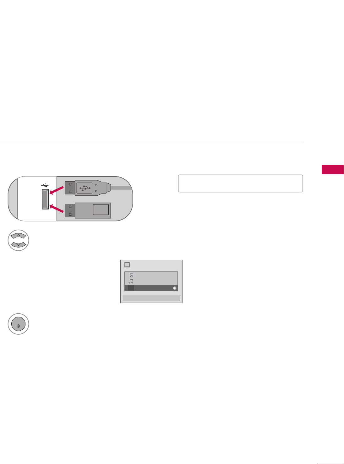
61
USB
1 Connect the USB device to the USB IN jack on the side of TV.
USB IN
Memory Key
or
2
Select PHOTO LIST, MUSIC LIST, or EXTRA CONTENTS.
i
Choose the media you want.
Close
Fl
Photo List
Music List
Extra Contents
3
ENTER
When you connect a USB device, this pop-up menu is displayed automatically.
When the Pop-Up menu does not appear, you can select Photo List or Music List on Extra contents.
On a USB device, you can not add a new folder or delete an existing folder.
USB
ENTRY MODES
V Image shown may differ from your TV.
V This TV supports playback of JPG pictures
and MP3 audio.
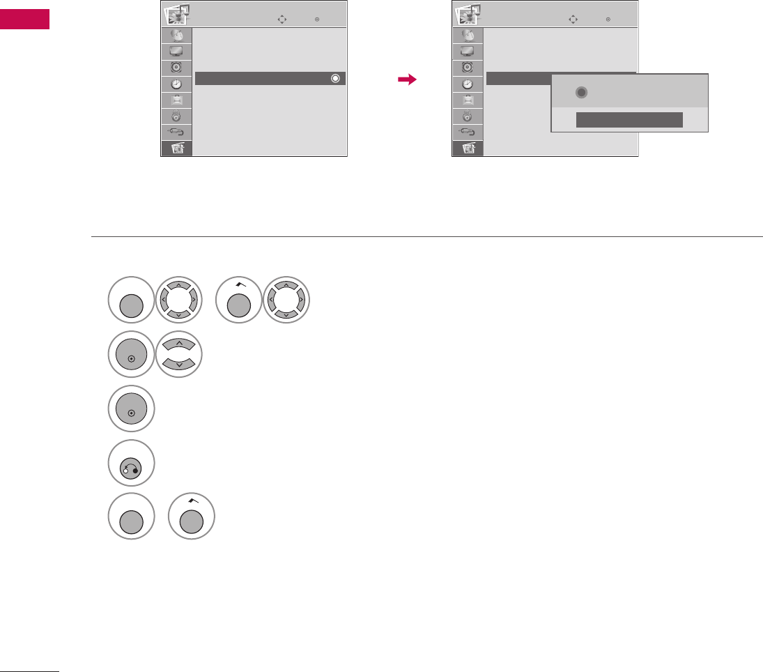
62
USB
USB
When removing the USB device
1
MENU
or
Home
Select USB.
2
ENTER
Select Eject.
3
ENTER
4
RETURN
Return to the previous menu.
MENU
or
Home
Return to TV viewing.
EnterMove
USB
Photo List
Music List
Extra Contents
Eject
ὤ㨴㥄
EnterMove
USB
Photo List
Music List
Extra Contents
Eject
i Now you can eject USB.
Close

63
USB
Precautions with USB devices.
G Only a USB storage device is recognizable.
G If the USB storage device is connected through a USB hub, the device is not recognizable.
G A USB storage device using an automatic recognition program may not be recognized.
G A USB storage device which uses its own driver may not be recognized.
G The recognition speed of a USB storage device may depend on each device.
G In case of a card reader, up to four memory cards are concurrently recognizable.
G Please do not turn off the TV or unplug the USB device when the connected USB storage device is working.
When such device is suddenly separated or unplugged, the stored files or the USB storage device may be
damaged.
G Only use a USB storage device which has normal music, image or movie files.
G Please connect power to a USB storage device (over 0.4A) which requires an external power supply. If not,
the device may not be recognized.
G Please connect a USB storage device with cable is offered by USB maker. If connected with cable is not
offered by USB maker or an excessively long cable, the device may not be recognized.
G Some USB storage devices may not be supported or operate properly.
G File alignment method of USB storage device is similar to Window XP and filename can recognize up to
100 English characters.
G Please backup important files because data on the USB device may be damaged. Data management is the
consumer's responsibility and as a result, the manufacturer does not cover data damage.
G Please use only a USB storage device which was formatted as a FAT32, NTFS file system provided with the
Windows operating system. In case of a storage device formatted as a different utility programme which is
not supported by Windows, it may not be recognized.
G Data in a USB storage device cannot be deleted in the NTFS file system.
G If your USB memory device has multiple partitions, or if you use a USB multi-card reader, you can use up
to 4 partitions or USB memory devices.
G The recommended capacity is 1TB or less for a USB external hard disk and 32GB or less for USB memory.
G Any device with more than the recommended capacity may not work properly.
G When using a USB HDD via the USB extensing cable, connect a support electric power source.
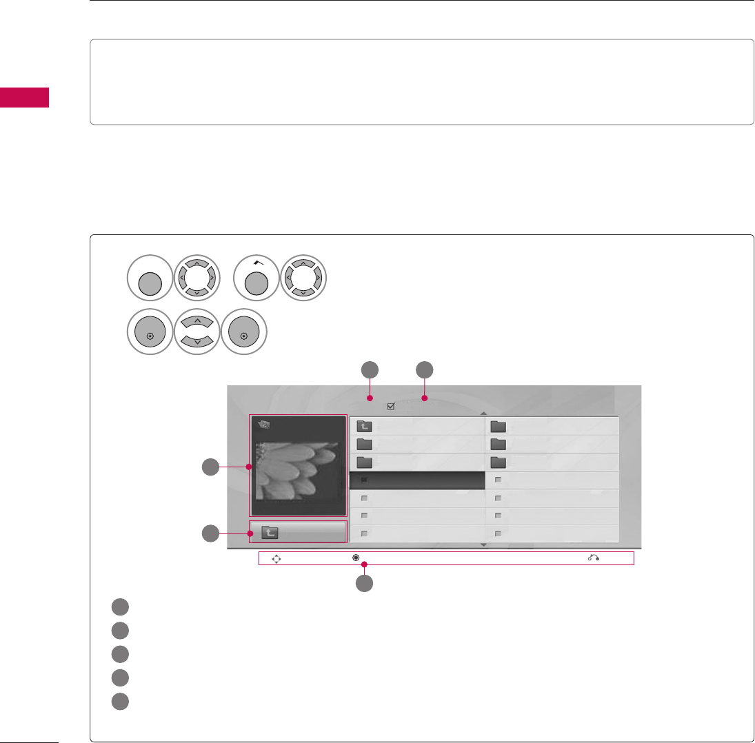
64
USB
USB
This TV only supports picture in JPEG(.jpg) format.
The On-Screen Display on your model may be slightly different.
Screen Components
PHOTO LIST
1
MENU
or
Home
Select USB.
2
ENTER
ENTER
Select Photo List.
Photo List
Page 2/3 No Marked
Drive1
Up Folder KY103 03/30/2011
JMJ001
KY101 06/10/2011 KY104 06/19/2011
KY102 04/03/2011 KY105 01/31/2011
JMJ001 01/01/2011 JMJ005 05/13/2011
1366x768, 125KB
JMJ002 06/15/2011 JMJ006 05/26/2011
JMJ003 04/03/2011 JMJ007 02/18/2011
Up Folder
JMJ004 02/18/2011 JMJ008 02/18/2011
ὤ㨴㥄
Navigation Popup Menu
ὤ㨴㥄
Exit
.3.4
.2
.1
.5
.1 Moves to upper level folder
.2 Preview: Displays the thumbnail/folder name of the photo in the selected folder
.3 Current page/Total pages
.4 Total number of marked photos
.5 Corresponding buttons on the remote control
Supported photo file: *.JPG
• You can view JPG files only.
• Only baseline scan is supported among JPG.
• Supported JPG size: 64 pixel (width) x 64 pixel (height) to 15360 pixel (width) x 8640 pixel (height)

65
USB
Photo Selection and Pop-up Menu
V When one or more photos are marked, you can
view individual photos or a slide show of the
marked photos. If no photos are marked, you can
view all photos individually or all photos in the
folder in a slide show.
1
Select the target folder or drive.
2
ENTER
Select the desired photos.
3
ENTER
Show the Pop-up menu.
4
ENTER
Select the desired Popup menu.
Photo List
Page 2/3 No Marked
Drive1
Up Folder KY103 03/30/2008
JMJ001
KY101 06/10/2008 KY104 06/19/2008
KY102 04/03/2008 KY105 01/31/2008
JMJ001 01/01/2000 JMJ005 05/13/2008
1366x768, 125KB
JMJ002 06/15/2008 JMJ006 05/26/2008
JMJ003 04/03/2008 JMJ007 02/18/2008
Up Folder JMJ004 02/18/2008 JMJ008 02/18/2008
ὤ㨴㥄
Navigation Popup Menu
ὤ㨴㥄
Exit
ὤ㨴㥄
Photo List
Page 2/3 No Marked
Drive1
Up Folder KY103 03/30/2008
JMJ001
KY101 06/10/2008 KY104 06/19/2008
KY102 04/03/2008 KY105 01/31/2008
JMJ001 01/01/2000 JMJ005 05/13/2008
1366x768, 125KB
JMJ002 06/15/2008 JMJ006 05/26/2008
JMJ003 04/03/2008 JMJ007 02/18/2008
Up Folder JMJ004 02/18/2008 JMJ008 02/18/2008
ὤ㨴㥄
Navigation Popup Menu
ὤ㨴㥄
Exit
1366x768, 125KB
View
Mark
Mark All
Delete
Close
When you select a file (not folder),
this Pop-Up menu is displayed.
G View: Display the selected item.
G Mark: Use to mark a photo.
G Unmark: Use to unmark a photo.
G Mark All: Mark all photos on the screen.
G Unmark All: Deselect all marked photos.
G Delete or Delete Marked
: Delete the selected photo item.
G Close: Close the pop-up menu.
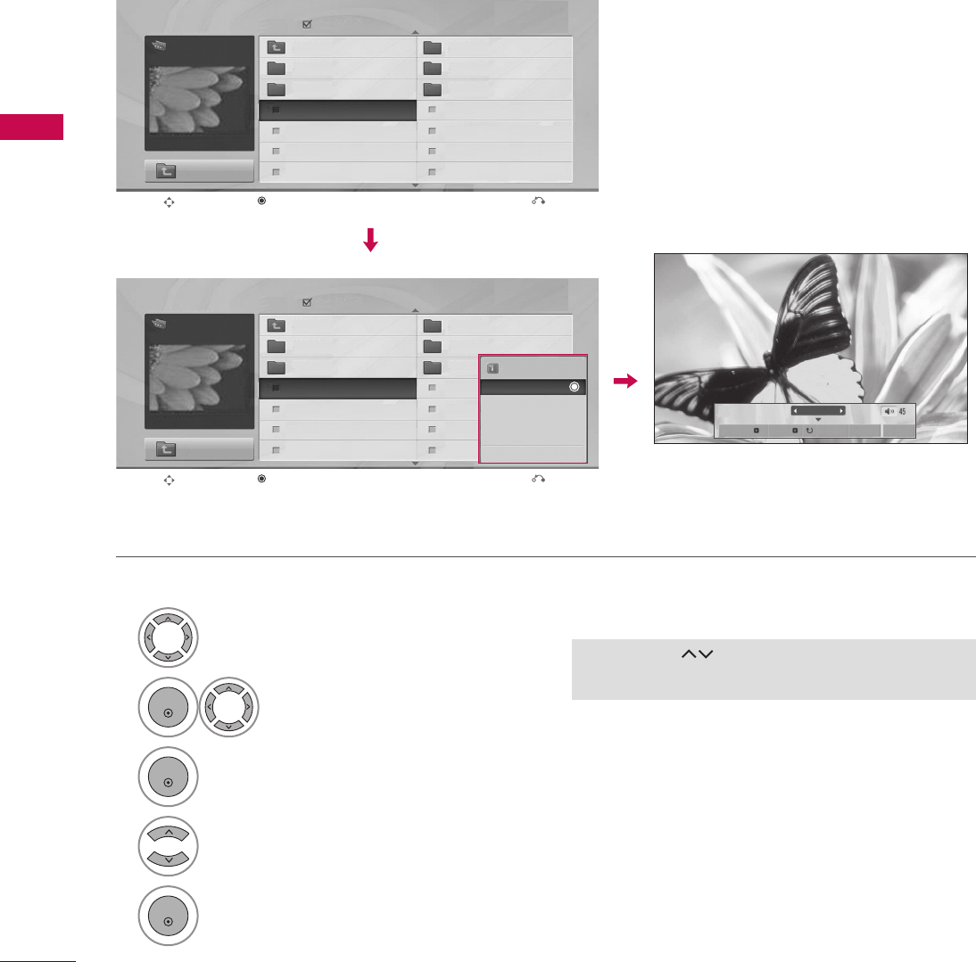
66
USB
USB
1
Select the target folder or drive.
2
ENTER
Select the desired photos.
3
ENTER
Show the Pop-up menu.
4
Select View.
5
ENTER
The selected photo is displayed in full size.
Full Screen Menu
You can change the Photo List view so that it fills the screen. More operations are available in full screen
mode.
ὤ㨴㥄
V Use the CH
ὤ㨴㥄
ὤ㨴㥄
button to navigate in the photo
page.
Photo List
Page 2/3 No Marked
Drive1
Up Folder KY103 03/30/2008
JMJ001
KY101 06/10/2008 KY104 06/19/2008
KY102 04/03/2008 KY105 01/31/2008
JMJ001 01/01/2000 JMJ005 05/13/2008
1366x768, 125KB
JMJ002 06/15/2008 JMJ006 05/26/2008
JMJ003 04/03/2008 JMJ007 02/18/2008
Up Folder JMJ004 02/18/2008 JMJ008 02/18/2008
ὤ㨴㥄
Navigation Popup Menu
ὤ㨴㥄
Exit
ὤ㨴㥄
Photo List
Page 2/3 No Marked
Drive1
Up Folder KY103 03/30/2008
JMJ001
KY101 06/10/2008 KY104 06/19/2008
KY102 04/03/2008 KY105 01/31/2008
JMJ001 01/01/2000 JMJ005 05/13/2008
1366x768, 125KB
JMJ002 06/15/2008 JMJ006 05/26/2008
JMJ003 04/03/2008 JMJ007 02/18/2008
Up Folder JMJ004 02/18/2008 JMJ008 02/18/2008
ὤ㨴㥄
Navigation Popup Menu
ὤ㨴㥄
Exit
1366x768, 125KB
View
Mark
Mark All
Delete
Close The aspect ratio of a photo may change the size of
the photo displayed on the screen in full size.
Press the RETURN button to move to the previous menu
screen.
1 /17
Slideshow BGM Delete Option Hide
ὤ㨴㥄
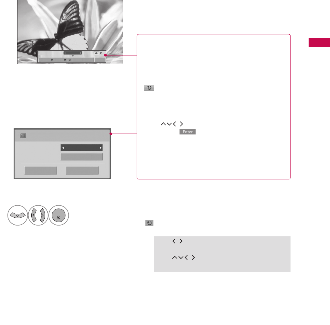
67
USB
V Use
ὤ㨴㥄
ὤ㨴㥄
button to select the previous or next
photo.
V Use
ὤ㨴㥄
ὤ㨴㥄
ὤ㨴㥄
ὤ㨴㥄
button to select and control the
menu on the full-sized screen.
6
ENTER
Select the Slideshow, BGM, (Rotate), Delete, Option, or Hide.
1 /17
Slideshow BGM Delete Option Hide
Press F G to set the time interval between slides.
Slide Speed Fast
Cancel
...
Music Album
Enter
G Slideshow: Selected photos are displayed during the
slide show. If no photo is selected, all photos in the
current folder are displayed during slide show.
V Set the time interval of the slide show in Option.
G BGM: Listen to music while viewing photos in full size.
V Set the BGM device and album in Option.
G (Rotate): Rotate photos.
V Rotates the photo 90°, 180°, 270°, 360° clockwise.
G Delete: Delete photos.
G Option: Set values for Slide Speed and Music Album.
V Use
ὤ㨴㥄
ὤ㨴㥄
ὤ㨴㥄
ὤ㨴㥄
button and ENTER button to set values.
Then go to and press ENTER to save the
settings.
V You cannot change Music Album while BGM is playing.
G Hide: Hide the menu on the full-sized screen.
V To see the menu again on the full-sized screen, press
ENTER button to display.
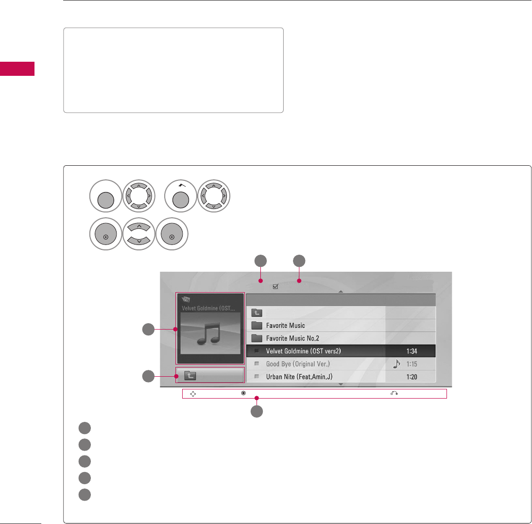
68
USB
USB
1
MENU
or
Home
Select USB.
2
ENTER
ENTER
Select Photo List.
Music List
Page 2/3 No Marked
Drive1 Title Duration
Up Folder
A 00:00 / 04:16
Up Folder
ὤ㨴㥄
Navigation Popup Menu
ὤ㨴㥄
Exit
.3.4
.2
.1
.5
.1 Moves to upper level folder
.2 Preview: If a supported picture of the album jacket is in the file, it will be displayed here.
.3 Current page/Total pages
.4 Total number of marked files
.5 Corresponding buttons on the remote control
You can use the Music List menu to play MP3 files from a USB storage device.
This TV cannot play back copy-protected files.
The On-Screen Display on your model may be slightly different.
Screen Components
MUSIC LIST
Supported music file: *.MP3
Bit rate range 32 Kbps - 320 Kbps
• Sampling rate (Sampling Frequency)
MPEG1 layer 3: 32 kHz, 44.1 kHz, 48 kHz
MPEG2 layer 3: 16 kHz, 22.05 kHz, 24 kHz
MPEG2.5 layer 3: 8 kHz, 11.025 kHz, 12 kHz
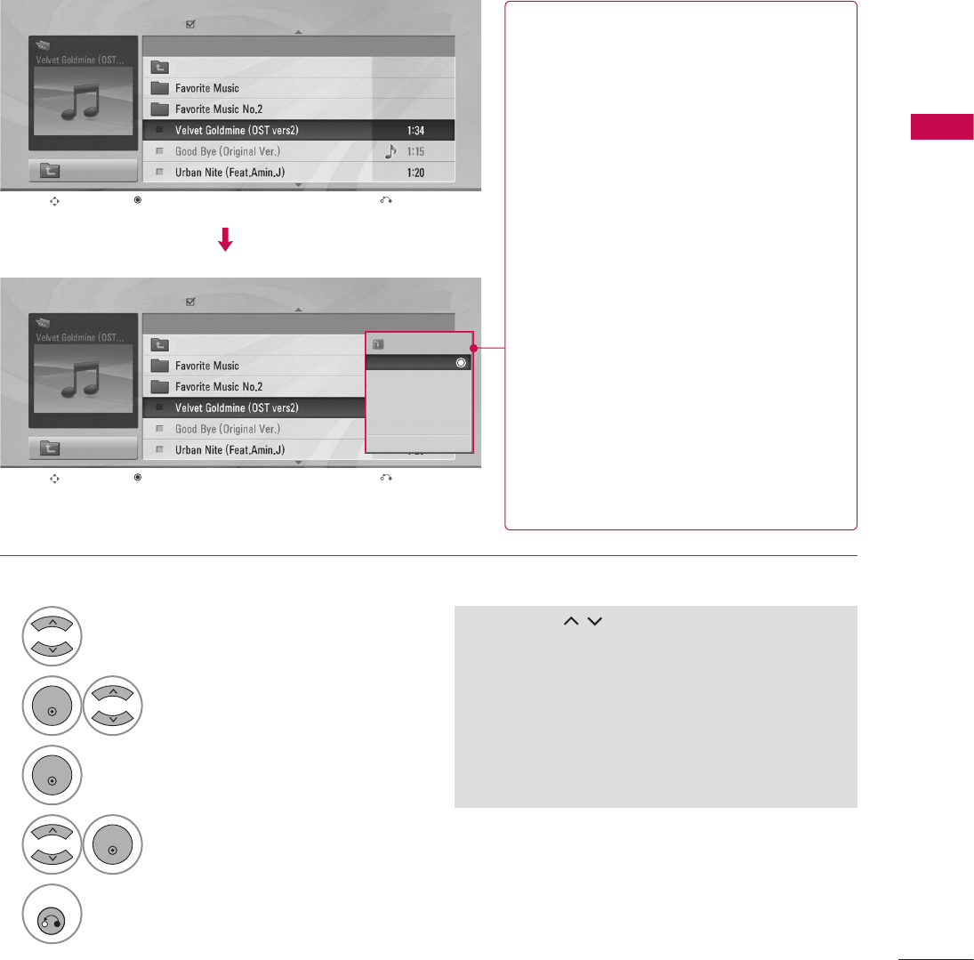
69
USB
Music Selection and Pop-up Menu
V Use the CH
ὤ㨴㥄
ὤ㨴㥄
button to navigate in the music
page.
V If no music is marked, all the music in the folder
will be played in sequence. When one or more
music files are marked, the marked music files will
be played in sequence. If you want to listen to
only one song repeatedly, just mark that one file
and play.
1
Select the target folder or drive.
2
ENTER
Select the desired musics.
3
ENTER
Show the Pop-up menu.
4
ENTER
Select the desired Pop-up menu.
5
RETURN
Return to TV viewing.
ὤ㨴㥄
Music List
Page 2/3 No Marked
Drive1 Title Duration
Up Folder
A 00:00 / 04:16
Up Folder
ὤ㨴㥄
Navigation Popup Menu
ὤ㨴㥄
Exit
Music List
Page 2/3 No Marked
Drive1 Title Duration
Up Folder
A 00:00 / 04:16
Up Folder
ὤ㨴㥄
Navigation Popup Menu
ὤ㨴㥄
Exit
3945 KB
128 Kbps
Play
Play with Photo
Mark
Mark All
Delete
Close
G Play (During stop): Play the selected file.
Once a song finishes playing, the next
selected one will be played. When there are
no selected files to play, the next one in the
current folder will be played. If you go to a
different folder and press the ENTER
button, the current song in playback will
stop.
G Play Marked: Play the selected files. Once
a file finishes playing, the next selected one
will be played automatically.
G Stop Play (During playback): Stop the
playing files.
G Play with Photo: Start playing the selected
files and then move to the Photo List.
G Mark: Use to mark a file.
G Unmark: Use to unmark a file.
G Mark All: Mark all files in the folder.
G Unmark All: Deselect all marked files.
G Delete or Delete Marked: Delete the
selected files.
G Close: Close the pop-up menu.
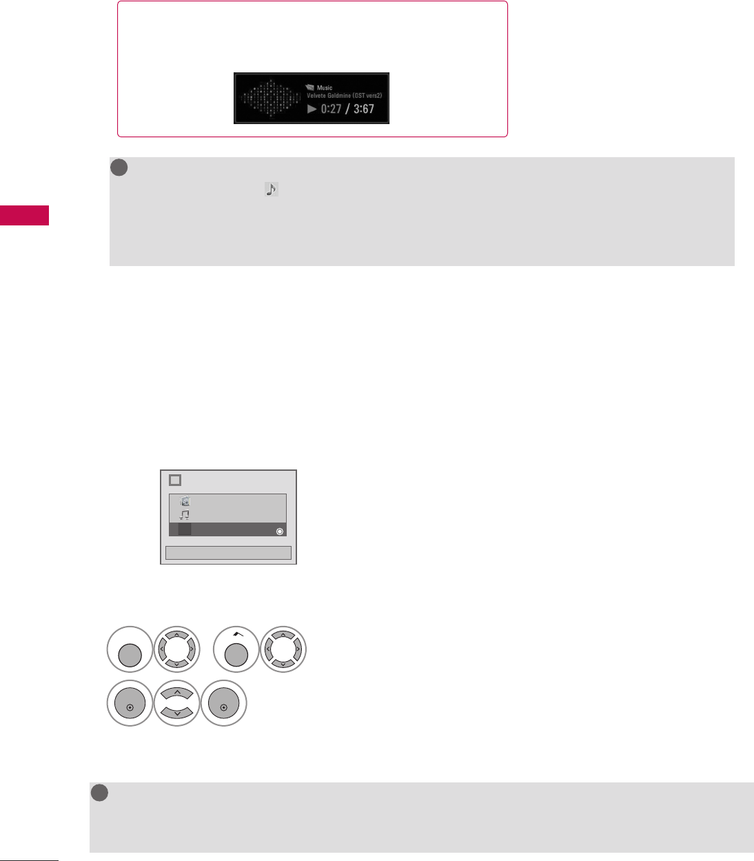
70
USB
USB
Extra Contents will be activated when Data Channel service is available.
i
Choose the media you want.
Close
Fl
Photo List
Music List
Extra Contents
NOTE
G Pro: Centric contents in USB memory stick can be played.
G For more information, contact to Customer Support.(www.lgcommercial.com)
!
?
!
?
! !
EXTRA CONTENTS
1
MENU
or
Home
Select USB.
2
ENTER
ENTER
Select Extra Contents.
V
The play information box (as shown below) will automatically
move across the screen when there is no user input to prevent a
fixed image remaining on the screen for a extended period of
time.
NOTE
G When music is playing, is displayed in front of the music play time.
G A damaged or corrupted music file that does not play displays 00:00 as the play time.
G Files downloaded from a paid service with copyright protection are not supported and will not play.
G Press ENTER, A, or RETURN button to stop the screen saver.
!
?
!
?
! !
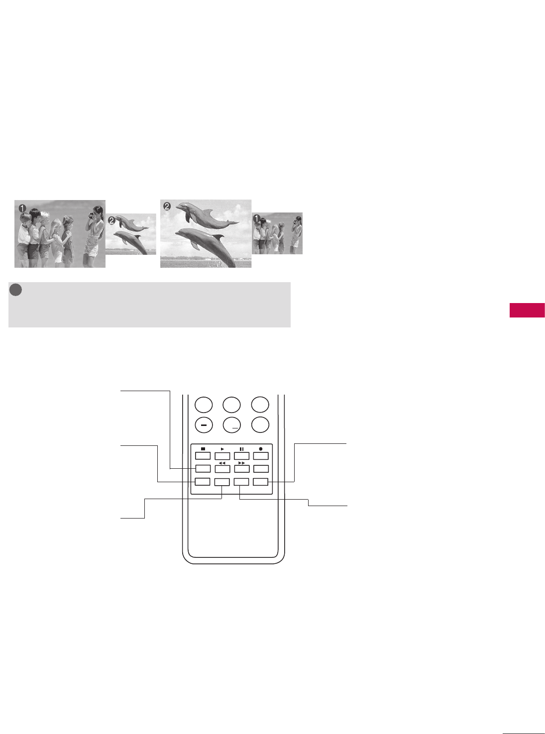
71
PICTURE CONTROL
PIP enables the end user to view two sources on the screen at the same time. The end user can switch
between the Main and Sub picture sizes.
REFERENCE
POINT
REFERENCE
POINT
PIP Operation
1. Connect auxiliary source(s) to TV
connections panel.
2. Enter Installer menu to be sure
source(s) is enabled.
3. Use the interactive remote provided
in the room to operate PIP.
4. Press PIP on remote.
Use the PIP function keys to operate
the available PIP features.
5. To exit PIP mode, simply press PIP.
123
456
789
0
ABC DEF
GHI JKL MNO
PQRS TUV WXYZ
PIP CH- PIP CH+
PIP SWAP PIP INPUT
PIP SAP
FLASHBK
REMOVE
ALPHA/NUM
P
A
G
E
MUTE
TIMER
MENU
RETURN
VOL CH
POWER
GUIDE
INPUT
CC
ENTER
TV DVD
VCR
STB
&@
.:/,
RATIO
PORTAL INFO i
REFERENCE
POINT
REFERENCE
POINT
PIP INPUT
Selects viewing source for PIP
window.
PIP SWAP
Switches Main screen and PIP
window sources.
PIP CH-
Selects next lower channel
for PIP window.
PIP CH+
Selects next higher channel
for PIP window.
PIP
Turns PIP mode on and off.
PICTURE CONTROL
PIP (PICTURE-IN-PICTURE)
NOTE
G Actual size of Main screen and PIP inset may be different than
shown above.
!
?
!
?
! !

72
PICTURE CONTROL
PICTURE CONTROL
REFERENCE
POINT
REFERENCE
POINT
Main Picture Source Available Sub Picture Sources
TV AV1, AV2, HDMI1, HDMI2
AV1or AV2 TV, AV1or AV2, HDMI1, HDMI2
HDMI1or HDMI2 TV, AV1, AV2, HDMI1or HDMI2
Component, RGB-PC TV, AV1, AV2, HDMI1, HDMI2
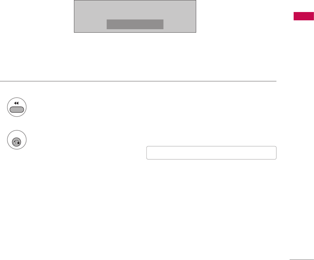
73
PICTURE CONTROL
This feature lets you choose the way an analog picture with a 4:3 aspect ratio is displayed on your TV.
V RGB-PC input source can only use 4:3 or 16:9 aspect ratio.
PICTURE SIZE (ASPECT RATIO) CONTROL
1
RATIO
Press the RATIO button repeatedly to select the picture options
: Set By Program, 4:3, 16:9, Zoom, Just Scan.
2
RETURN
Return to TV viewing. V You can also adjust Aspect Ratio in the
PICTURE menu.
16:9
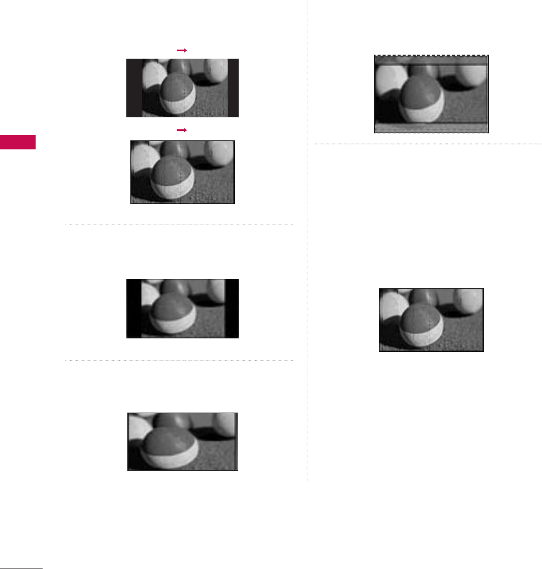
74
PICTURE CONTROL
PICTURE CONTROL
Set by program
Selects the proper picture proportion to match
the source’s image.
(4:3
ὤ㨴㥄
4:3)
Set By Program
(16:9
ὤ㨴㥄
16:9)
Set By Program
4:3
Choose 4:3 when you want to view a picture
with an original 4:3 aspect ratio.
16:9
Adjust the picture horizontally, in a linear
proportion to fill the entire screen.
Zoom
Choose Zoom when you want to view the picture
without any alteration. However, the top and
bottom portions of the picture will be cropped.
Just Scan
Normally the edges of video signals are cropped
1-2%. Just Scan turns off this cropping and
shows the complete video.
Notes: If there is noise on the edges of the
original signal, it will be visible when Just Scan is
activated.
Just Scan operates only with DTV/CADTV/
HDMI-DTV/DVI-DTV (720p/1080i),
Component(720p/1080i) input sources.
Just Scan
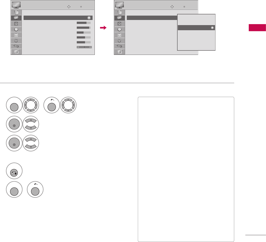
75
PICTURE CONTROL
There are factory presets for picture settings available in the user menus.
You can use a preset, change each setting manually, or use the Intelligent Sensor.
PRESET PICTURE SETTINGS (PICTURE MODE)
1
MENU
or
Home
Select PICTURE.
2
ENTER
Select Picture Mode.
3
ENTER
Select Intelligent Sensor, Vivid, Standard,
Natural, Cinema, Sport or Game.
4
RETURN
Return to the previous menu.
MENU
or
Home
Return to TV viewing.
V When selecting Intelligent Sensor is
changed to Auto automatically.
V When selecting Intelligent Sensor, it is
changed contrast, brightness, sharpness,
color and tint automatically.
V Vivid, Standard, Natural, Cinema, Sport,
and Game Settings are preset for the
optimum picture quality at the factory.
V Intelligent Sensor: The most suitable
picture is automatically adjusted according
to the surrounding conditions.
V Vivid: This is the mode to maximize the
effect of the video in the retail store.
Strengthen the contrast, brightness, color
and sharpness for vivid picture.
V Standard: This is the mode to realize
optimum viewing condition for the general
user.
V Natural: This is the mode to display the
most natural screen status.
V Cinema: This mode optimizes video for
watching movies.
V Sport: This is the video mode to emphasize
dynamic video and primary color (e.g, white,
uniform, grass, sky blue etc.) by realizing the
optimal screen for sports.
V Game: This is the mode to realize fast
response speed in a fast gaming screen.
EnterMove
PICTURE
Aspect Ratio : 16:9
Picture Mode : Standard
• BackLight 70
• Contrast 90
• Brightness 50
• Sharpness 30
• Color 60
• Tint 0 R G
E
EnterMove
PICTURE
Aspect Ratio : 16:9
Picture Mode : Standard
• BackLight 70
• Contrast 90
• Brightness 50
• Sharpness 30
• Color 60
• Tint 0 R G
E
R G
Intelligent Sensor
Vivid
Standard
Natural
Cinema
Sport
Game
ὤ㨴㥄
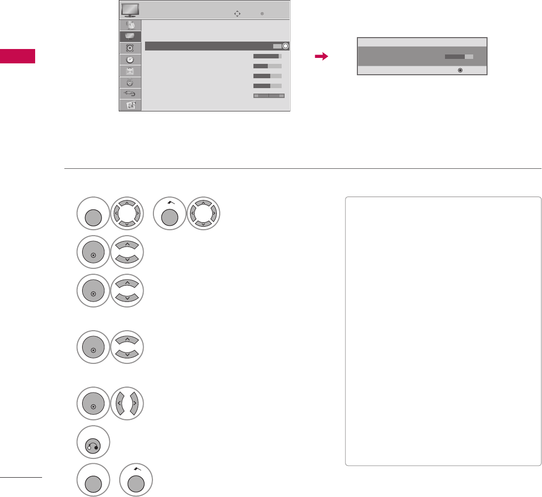
76
PICTURE CONTROL
PICTURE CONTROL
Adjust the picture appearance to suit your preference and viewing situations.
This feature is disable in “Picture Mode-Intelligent Sensor”.
MANUAL PICTURE ADJUSTMENT - USER MODE
1
MENU
or
Home
Select PICTURE.
2
ENTER
Select Picture Mode.
3
ENTER
Select Vivid, Standard, Natural,
Cinema, Sport or Game.
4
ENTER
Select Backlight, Contrast, Brightness,
Sharpness, Color, or Tint.
5
ENTER
Make appropriate adjustments.
6
RETURN
Return to the previous menu.
MENU
or
Home
Return to TV viewing.
V Backlight: This function adjusts the
brightness of LCD panel, to control the
brightness of the screen. Adjusting the
backlight is recommended when setting the
brightness of the set. When decreasing the
backlight, the brightness of the black
becomes darker without any loss in video
signal and the power consumption is
reduced.
V Contrast: Increase or decrease the gradient
of the video signal. You may use Contrast
when the bright part of picture is saturated.
V Brightness: Adjusts the base level of the
signal in the picture. You may use Brightness
when the dark part of the picture is
saturated.
V Sharpness: Adjusts the level of crispness in
the edges between the light and dark areas
of the picture. The lower the level, the softer
the image.
V Color: Adjusts intensity of all colors.
V Tint: Adjusts the balance between red and
green levels.
EnterMove
PICTURE
Aspect Ratio : 16:9
Picture Mode : Standard
• BackLight 70
• Contrast 90
• Brightness 50
• Sharpness 30
• Color 60
• Tint 0 R G
E
ὤ㨴㥄
D
• BackLight 70 F G
E Enter
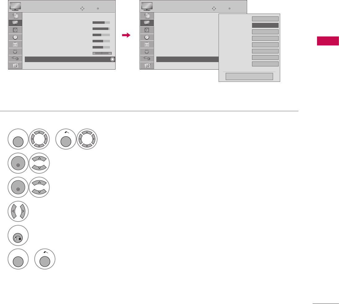
77
PICTURE CONTROL
You can calibrate the screen for each Picture Mode or set the video value according to the special video screen.
You can set the video seeing differently for each input.
To reset to the factory default after making adjustments to each input source, execute the Picture Reset
function for each Picture Mode.
PICTURE IMPROVEMENT TECHNOLOGY
1
MENU
or
Home
Select PICTURE.
2
ENTER
Select Advanced Control.
3
ENTER
Select your desired options.
4
Make appropriate adjustments.
5
RETURN
Return to the previous menu.
MENU
or
Home
Return to TV viewing.
EnterMove
PICTURE
Picture Mode : Standard
• BackLight 70
• Contrast 90
• Brightness 50
• Sharpness 30
• Color 60
• Tint 0 R G
• Advanced Control
E
ὤ㨴㥄
EnterMove
PICTURE
Picture Mode : Standard
• BackLight 70
• Contrast 90
• Brightness 50
• Sharpness 30
• Color 60
• Tint 0 R G
• Advanced Control
E
Color Temperature Medium
Dynamic Contrast F Medium G
Dynamic Color Low
Noise Reduction Medium
Gamma Medium
Black Level Low
Eye Care Off
Real Cinema Off
E
Close

78
PICTURE CONTROL
PICTURE CONTROL
Color Temperature V Set to warm to enhance hotter colors such as red, or set to cool to enhance cooler
colors such as blue.
Dynamic Contrast
V Adjusts the contrast to keep it at the best level according to the brightness of the
screen. The picture is improved by making bright parts brighter and dark parts
darker.
Dynamic Color
V Adjusts screen colors so that they look livelier, richer and clearer. This feature
enhances hue, saturation and luminance so that red, blue, green and white look more
vivid.
Noise Reduction V Reduces screen noise without compromising video quality.
Gamma
Low : Make dark and middle gray level area of the picture brighter.
Medium: Express original picture levels.
High: Make dark and middle gray level area of the picture darker.
V You can adjust brightness of dark area and middle gray level area of the picture.
Black Level
Low: The reflection of the screen gets darker.
High: The reflection of the screen gets brighter.
V Set black level of the screen to proper level.
V This function enables to select 'Low' or 'High' in the following mode: AV (NTSC-M),
HDMI or Component.
Eye Care
V Adjust the brightness of the screen to prevent the screen from being too bright.
Dims extremely bright pictures.
V This feature is disabled in “Picture Mode-Intelligent Sensor, Vivid, Cinema”.
Real Cinema V Makes video clips recorded in film look more natural by eliminating judder effect.
TruMotion
(Depending on model)
High: Provides smoother picture movement.
Low: Provides smooth picture movement. Use this setting for standard use.
Off: Turn off TruMotion operation.
V Advance video technology that provides clearer, smoother images, even during fast
action scenes creating a more stable structure for a crisper picture.
V TruMotion works with all inputs except PC mode.
V If you enable “TruMotion”, noise may appear on the screen. If this occurs, set
“TruMotion” to “Off”.
V If you select “Picture Mode-Game”, set “TruMotion” to “Off”.
Color Gamut
Standard: Displays standard set of colors.
Wide: Increase number of colors used.
V Maximize the utilization of color to increase color quality.
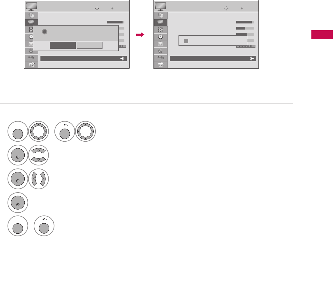
79
PICTURE CONTROL
Settings of the selected picture modes return to the default factory settings.
PICTURE RESET
1
MENU
or
Home
Select PICTURE.
2
ENTER
Select Picture Reset.
3
ENTER
Select Yes.
4
ENTER
Initialize the adjusted value.
5
MENU
or
Home
Return to TV viewing.
ὤ㨴㥄
EnterMove
PICTURE
D
• Contrast 90
• Brightness 50
• Sharpness 30
• Color 60
• Tint 0 R G
• Advanced Control
• Picture Reset
Screen (RGB-PC)
? All picture settings will be resetted.
Continue?
Yes
No
EnterMove
PICTURE
D
• Contrast 90
• Brightness 50
• Sharpness 30
• Color 60
• Tint 0 R G
• Advanced Control
• Picture Reset
Screen (RGB-PC)
i Resetting video configuration...
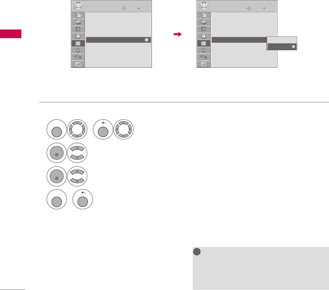
80
PICTURE CONTROL
PICTURE CONTROL
Displays a slide show to explain the various features of this TV.
NOTE
G Data Broadcasting: For 32/37/42LG710H,
32/37/42/47/55LD650H, 32/37/42LD655H
G Zone: For 32/37/42LD660H,
32/37/42LD665H, 32/37/42/47/55LV555H
!
?
!
?
! !
DEMO MODE
1
MENU
or
Home
Select OPTION.
2
ENTER
Select Demo Mode.
3
ENTER
Select On to show the various feature of the TV.
4
MENU
or
Home
Return to TV viewing.
After a while, Demo Mode starts.
If you want to stop the demo, press any button
(Except VOL +, - and MUTE button).
ὤ㨴㥄
EnterMove
OPTION
Menu Language : English
Audio Language : English
Caption : Off
Set ID : 1
Demo Mode : Off
Data Broadcasting
Zone
EnterMove
OPTION
Menu Language : English
Audio Language : English
Caption : Off
Set ID : 1
Demo Mode : Off
Data Broadcasting
Zone
Off
On
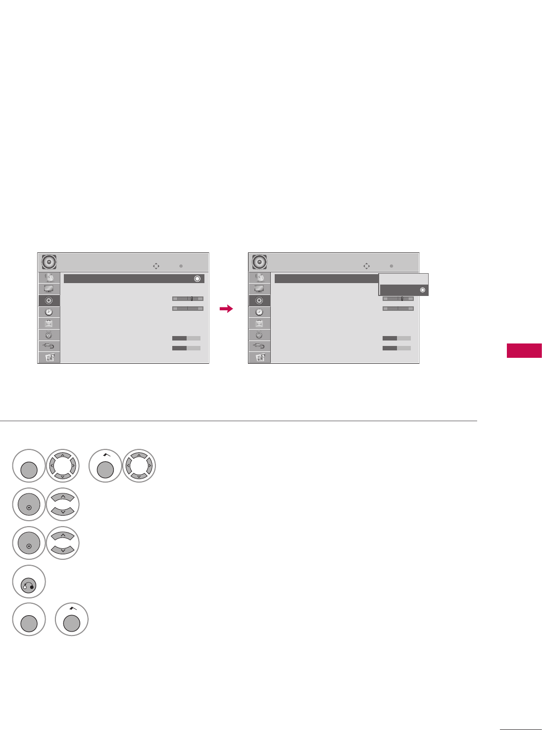
81
SOUND & LANGUAGE CONTROL
Auto Volume makes sure that the volume level remains consistent whether you are watching a commercial or a
regular TV program.
Because each broadcasting station has its own signal conditions, volume adjustment may be needed every
time the channel is changed. This feature allows users to enjoy stable volume levels by making automatic
adjustments for each program.
SOUND & LANGUAGE CONTROL
AUTO VOLUME LEVELER (AUTO VOLUME)
1
MENU
or
Home
Select AUDIO.
2
ENTER
Select Auto Volume.
3
ENTER
Select On or Off.
4
RETURN
Return to the previous menu.
MENU
or
Home
Return to TV viewing.
EnterMove
AUDIO
Auto Volume : Off
Clear Voice II : On
• Level 3 - +
Balance 0 L R
Sound Mode : Standard
• SRS TruSurround XT: Off
• Treble 50
• Bass 50
E
ὤ㨴㥄
EnterMove
AUDIO
Auto Volume : On
Clear Voice II : On
• Level 3 - +
Balance 0 L R
Sound Mode : Standard
• SRS TruSurround XT: Off
• Treble 50
• Bass 50
E
Off
On
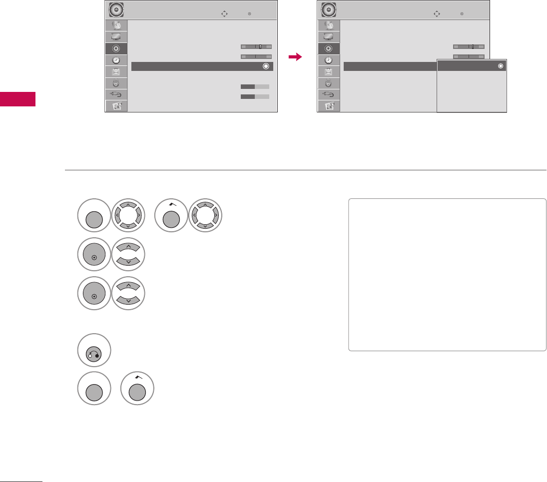
82
SOUND & LANGUAGE CONTROL
SOUND & LANGUAGE CONTROL
1
MENU
or
Home
Select AUDIO.
2
ENTER
Select Sound Mode.
3
ENTER
Select Standard, Music,
Cinema, Sport, or Game.
4
RETURN
Return to the previous menu.
MENU
or
Home
Return to TV viewing.
Sound Mode lets you enjoy the best sound without any special adjustment as the TV sets the appropriate
sound options based on the program content.
PRESET SOUND SETTINGS (SOUND MODE)
V Standard, Music, Cinema, Sport, and
Game are preset for optimum sound quality
at the factory.
V Standard: Offers standard-quality sound.
V Music: Optimizes sound for listening to
music.
V Cinema: Optimizes sound for watching
movies.
V Sport: Optimizes sound for watching sports
events.
V Game: Optimizes sound for playing games.
EnterMove
AUDIO
Auto Volume : Off
Clear Voice II : On
• Level 3 - +
Balance 0 L R
Sound Mode : Standard
• SRS TruSurround XT: Off
• Treble 50
• Bass 50
E
ὤ㨴㥄
EnterMove
AUDIO
Auto Volume : Off
Clear Voice II : On
• Level 3 - +
Balance 0 L R
Sound Mode : Standard
• SRS TruSurround XT: Off
• Treble 50
• Bass 50
E
Standard
Music
Cinema
Sport
Game
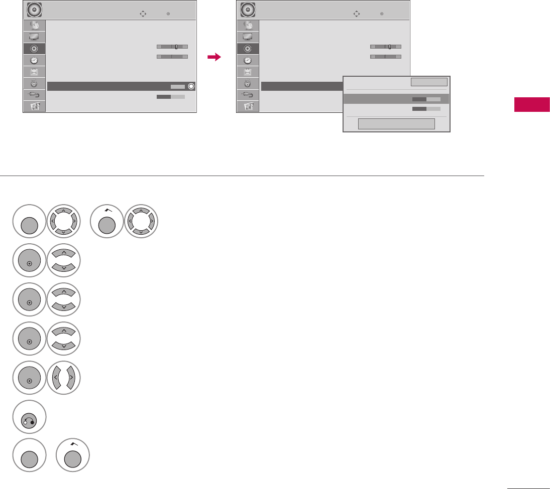
83
SOUND & LANGUAGE CONTROL
Adjust the sound to suit your taste and room situations.
SOUND SETTING ADJUSTMENT - USER MODE
1
MENU
or
Home
Select AUDIO.
2
ENTER
Select Sound Mode.
3
ENTER
Select Standard, Music, Cinema, Sport, or Game.
4
ENTER
Select Treble or Bass.
5
ENTER
Make appropriate adjustments.
6
RETURN
Return to the previous menu.
MENU
or
Home
Return to TV viewing.
EnterMove
AUDIO
Auto Volume : Off
Clear Voice II : On
• Level 3 - +
Balance 0 L R
Sound Mode : Standard
• SRS TruSurround XT: Off
• Treble 50
• Bass 50
E
ὤ㨴㥄
EnterMove
AUDIO
Auto Volume : Off
Clear Voice II : On
• Level 3 - +
Balance 0 L R
Sound Mode : Standard
• SRS TruSurround XT: Off
• Treble 50
• Bass 50
E
• SRS TruSurround XT Off
• BackLight 50 F G
• Bass 50
Close
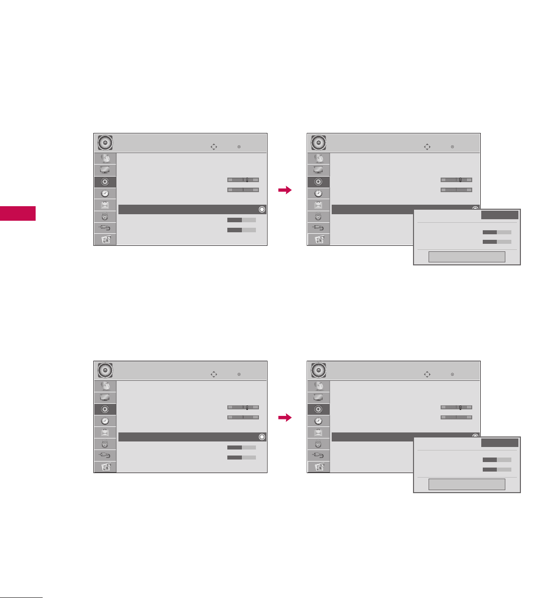
84
SOUND & LANGUAGE CONTROL
SOUND & LANGUAGE CONTROL
Takes advantage of any multi-channel format without needing to add extra speakers or equipment. Dialog
clarity, bass enrichment, and the addition of stereo audio enhancement produces an immersive sound
experience from standard stereo material.
32/37/42LG710H
32/37/42/47/55LD650H, 32/37/42LD655H, 32/37/42LD660H, 32/37/42LD665H,
32/37/42/47/55LV555H
SRS TRUSURROUND XT / INFINITE SOUND
EnterMove
AUDIO
Auto Volume : Off
Clear Voice II : On
• Level 3 - +
Balance 0 L R
Sound Mode : Standard
• SRS TruSurround XT: Off
• Treble 50
• Bass 50
E
ὤ㨴㥄
EnterMove
AUDIO
Auto Volume : Off
Clear Voice II : On
• Level 3 - +
Balance 0 L R
Sound Mode : Standard
• SRS TruSurround XT: Off
• Treble 50
• Bass 50
E
• SRS TruSurround XT Off
• BackLight 50
• Bass 50
Close
EnterMove
AUDIO
Auto Volume : Off
Clear Voice II : On
• Level 3 - +
Balance 0 L R
Sound Mode : Standard
• Infinite Sound: Off
• Treble 50
• Bass 50
E
ὤ㨴㥄
EnterMove
AUDIO
Auto Volume : Off
Clear Voice II : On
• Level 3 - +
Balance 0 L R
Sound Mode : Standard
• Infinite Sound: Off
• Treble 50
• Bass 50
E
• Infinite Sound Off
• BackLight 50
• Bass 50
Close
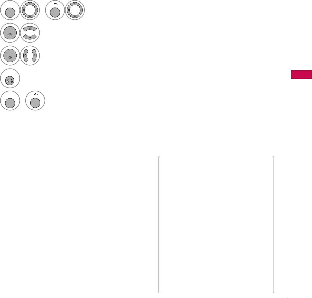
85
SOUND & LANGUAGE CONTROL
1
MENU
or
Home
Select AUDIO.
2
ENTER
Select SRS TruSurround XT or Infinite Sound.
3
ENTER
Select On or Off.
4
RETURN
Return to the previous menu.
MENU
or
Home
Return to TV viewing.
V If sound quality or volume is not at the
level you want, it is recommended to use a
separate home theater system or amp to
cope with different user environments.
V If you select “Clear Voice II-On”, SRS
TruSurround XT feature will not work.
V SRS TruSurround XT: TruSurround XT is a
patented SRS technology that solves the
problem of playing 5.1 multichannel
content over two speakers.
V Infinite Sound: Infinite Sound is a patented
LG proprietary sound processing
technology that strives immersive 5.1
surround sound with just two front
speakers. (For 32/37/42/47/55LD650H,
32/37/42LD655H, 32/37/42LD660H,
32/37/42LD665H,
32/37/42/47/55LV555H)
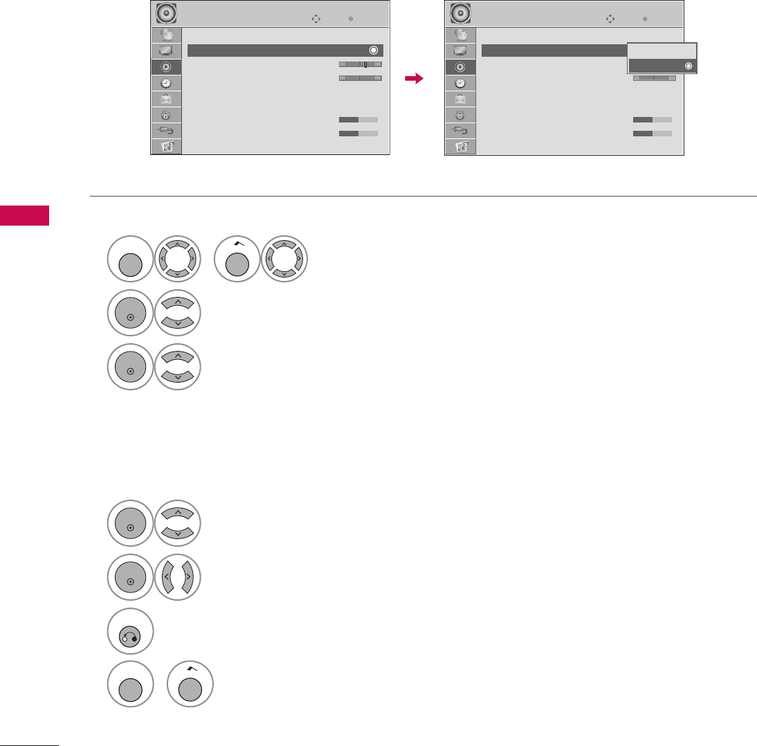
86
SOUND & LANGUAGE CONTROL
SOUND & LANGUAGE CONTROL
By differentiating the human sound range from others, it improves the sound quality of voices.
CLEAR VOICE II
1
MENU
or
Home
Select AUDIO.
2
ENTER
Select Clear Voice II.
3
ENTER
Select On or Off.
4
ENTER
Select Level.
5
ENTER
Make appropriate adjustments.
6
RETURN
Return to the previous menu.
MENU
or
Home
Return to TV viewing.
Adjustment for Clear Voice ll Level With selecting On
EnterMove
AUDIO
Auto Volume : Off
Clear Voice II : On
• Level 3 - +
Balance 0 L R
Sound Mode : Standard
• SRS TruSurround XT: Off
• Treble 50
• Bass 50
E
ὤ㨴㥄
EnterMove
AUDIO
Auto Volume : Off
Clear Voice II : On
• Level 3 - +
Balance 0 L R
Sound Mode : Standard
• SRS TruSurround XT: Off
• Treble 50
• Bass 50
E
Off
On
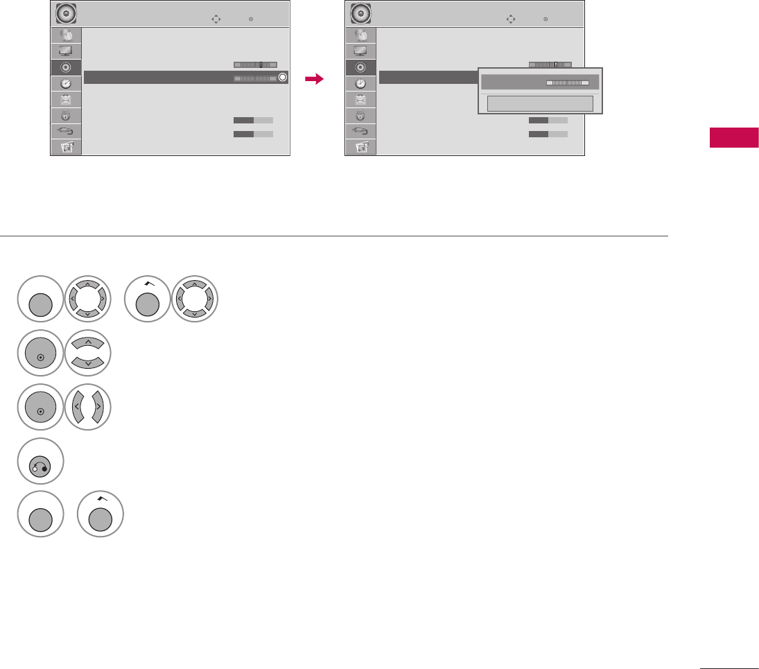
87
SOUND & LANGUAGE CONTROL
Adjust the left/right sound of speaker to suit your taste and room situations.
BALANCE
1
MENU
or
Home
Select AUDIO.
2
ENTER
Select Balance.
3
ENTER
Make appropriate adjustments.
4
RETURN
Return to the previous menu.
MENU
or
Home
Return to TV viewing.
EnterMove
AUDIO
Auto Volume : Off
Clear Voice II : On
• Level 3 - +
Balance 0 L R
Sound Mode : Standard
• SRS TruSurround XT: Off
• Treble 50
• Bass 50
E
ὤ㨴㥄
EnterMove
AUDIO
Auto Volume : Off
Clear Voice II : On
• Level 3 - +
Balance 0 L R
Sound Mode : Standard
• SRS TruSurround XT: Off
• Treble 50
• Bass 50
E
BackLight 0 FL R G
Close
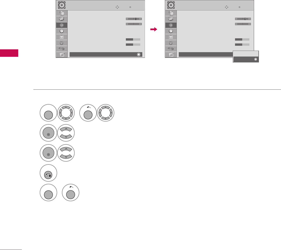
88
SOUND & LANGUAGE CONTROL
SOUND & LANGUAGE CONTROL
If you wish to use an external Hi-Fi system or a SRS System, turn off the TV’s internal speakers.
In AV, Component, RGB and HDMI with HDMI to DVI cable, the TV speaker can be operational even when there
is no video signal.
Turn the TV speakers off if using external audio equipment.
TV SPEAKERS ON/OFF SETUP
1
MENU
or
Home
Select AUDIO.
2
ENTER
Select TV Speaker.
3
ENTER
Select On or Off.
4
RETURN
Return to the previous menu.
MENU
or
Home
Return to TV viewing.
EnterMove
AUDIO
D
• Level 3 - +
Balance 0 L R
Sound Mode : Standard
• SRS TruSurround XT: Off
• Treble 50
• Bass 50
• Reset
TV Speaker : On
ὤ㨴㥄
EnterMove
AUDIO
D
• Level 3 - +
Balance 0 L R
Sound Mode : Standard
• SRS TruSurround XT: Off
• Treble 50
• Bass 50
• Reset
TV Speaker : On Off
On
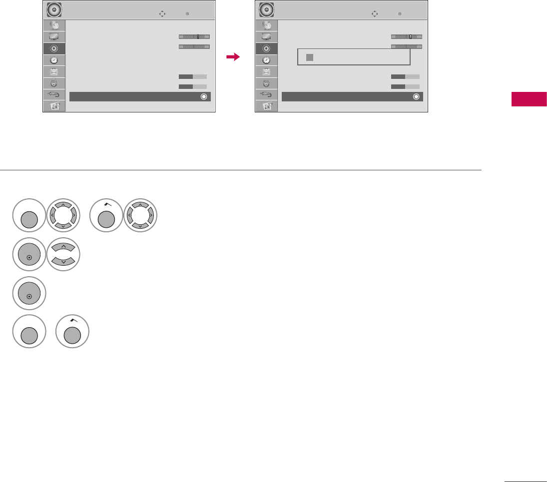
89
SOUND & LANGUAGE CONTROL
Settings of the selected Sound Mode return to the default factory settings.
AUDIO RESET
1
MENU
or
Home
Select AUDIO.
2
ENTER
Select Reset.
3
ENTER
Initialize the adjusted value.
4
MENU
or
Home
Return to TV viewing.
EnterMove
AUDIO
D
• Level 3 - +
Balance 0 L R
Sound Mode : Standard
• SRS TruSurround XT: Off
• Treble 50
• Bass 50
• Reset
E
ὤ㨴㥄
EnterMove
AUDIO
D
• Level 3 - +
Balance 0 L R
Sound Mode : Standard
• SRS TruSurround XT: Off
• Treble 50
• Bass 50
• Reset
E
i Resetting audio configuration...
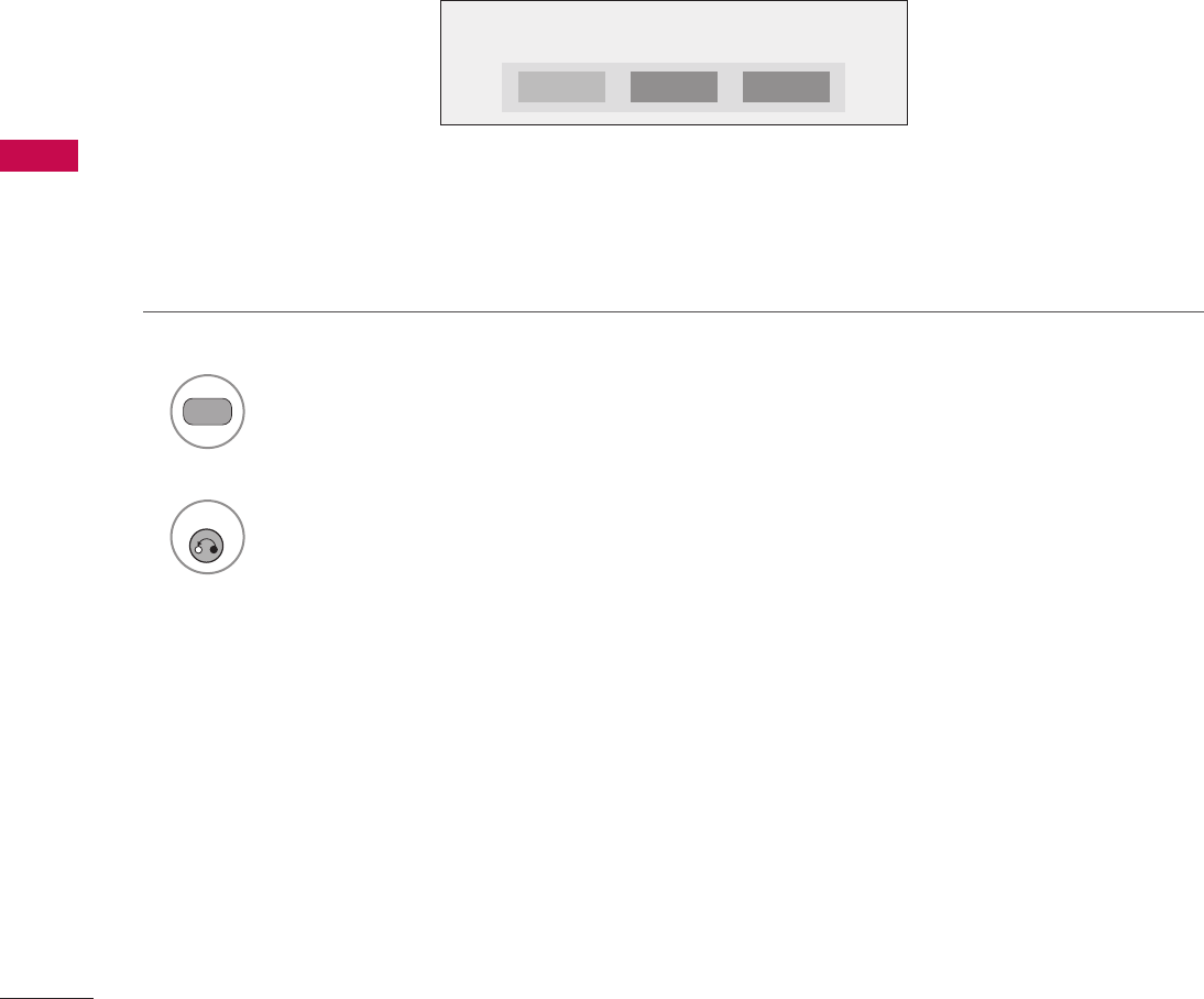
90
SOUND & LANGUAGE CONTROL
SOUND & LANGUAGE CONTROL
For Analog only: This TV can receive MTS stereo programs and any SAP (Secondary Audio Program) that
accompanies the stereo program if the station transmits an additional sound signal. Mono sound is
automatically used if the broadcast is only in Mono.
If other languages are available on the digital signal, select them with the SAP button.
STEREO/SAP BROADCAST SETUP
1
SAP
Each time you press the SAP button,
Mono, Stereo, or SAP appear in turn.
2
RETURN
Return to TV viewing.
STEREO SAPMONO
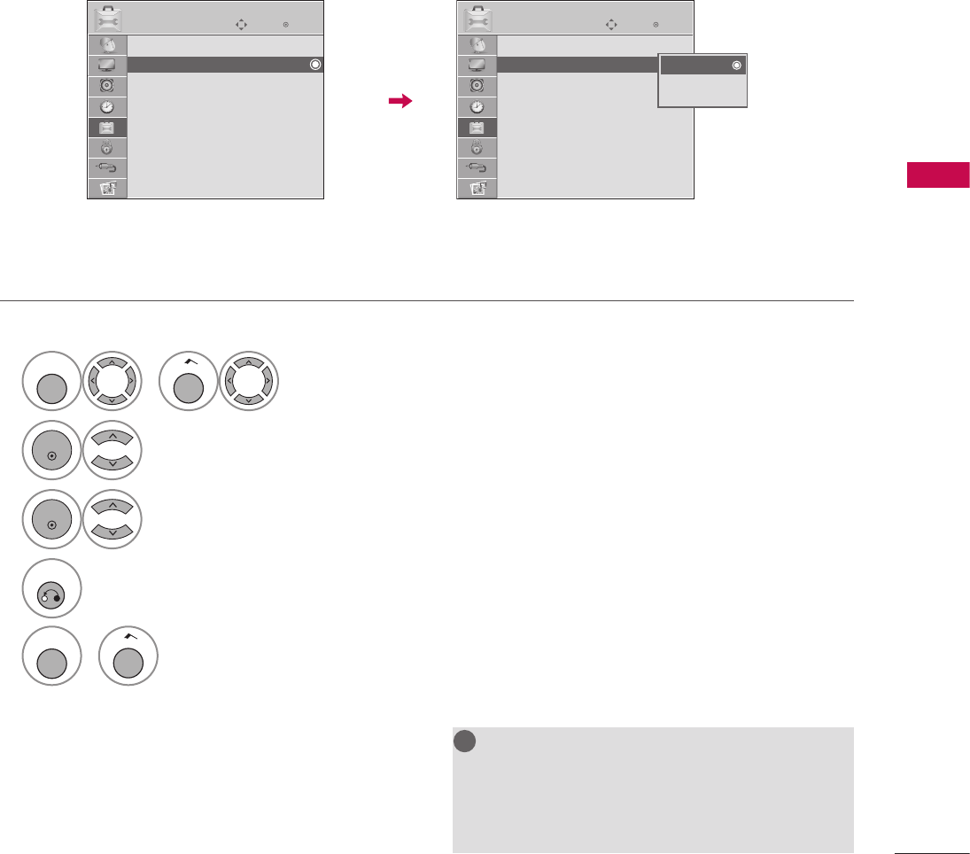
91
SOUND & LANGUAGE CONTROL
Other languages may be available if a digital signal is provided by the broadcasting station.
This feature operates only in DTV mode.
NOTE
G Data Broadcasting: For 32/37/42LG710H,
32/37/42/47/55LD650H, 32/37/42LD655H
G Zone: For 32/37/42LD660H,
32/37/42LD665H, 32/37/42/47/55LV555H
!
?
!
?
! !
AUDIO LANGUAGE
1
MENU
or
Home
Select OPTION.
2
ENTER
Select Audio Language.
3
ENTER
Select your desired language.
4
RETURN
Return to the previous menu.
MENU
or
Home
Return to TV viewing.
ὤ㨴㥄
EnterMove
OPTION
Menu Language : English
Audio Language : English
Caption : Off
Set ID : 1
Demo Mode : Off
Data Broadcasting
Zone
EnterMove
OPTION
Menu Language : English
Audio Language : English
Caption : Off
Set ID : 1
Demo Mode : Off
Data Broadcasting
Zone
English
Spanish
French
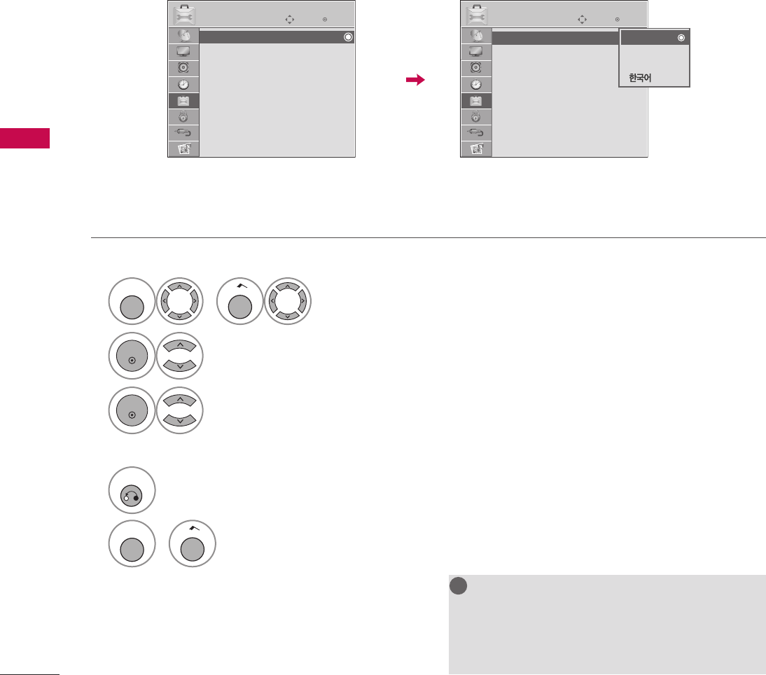
92
SOUND & LANGUAGE CONTROL
SOUND & LANGUAGE CONTROL
The menus can be shown on the screen in the selected language.
NOTE
G Data Broadcasting: For 32/37/42LG710H,
32/37/42/47/55LD650H, 32/37/42LD655H
G Zone: For 32/37/42LD660H,
32/37/42LD665H, 32/37/42/47/55LV555H
!
?
!
?
! !
ON-SCREEN MENUS LANGUAGE SELECTION
1
MENU
or
Home
Select OPTION.
2
ENTER
Select Menu Language.
3
ENTER
Select your desired language.
From this point on, the on-screen menus will be shown in the selected language.
4
RETURN
Return to the previous menu.
MENU
or
Home
Return to TV viewing.
ὤ㨴㥄
EnterMove
OPTION
Menu Language : English
Audio Language : English
Caption : Off
Set ID : 1
Demo Mode : Off
Data Broadcasting
Zone
EnterMove
OPTION
Menu Language : English
Audio Language : English
Caption : Off
Set ID : 1
Demo Mode : Off
Data Broadcasting
Zone
English
Español
Français
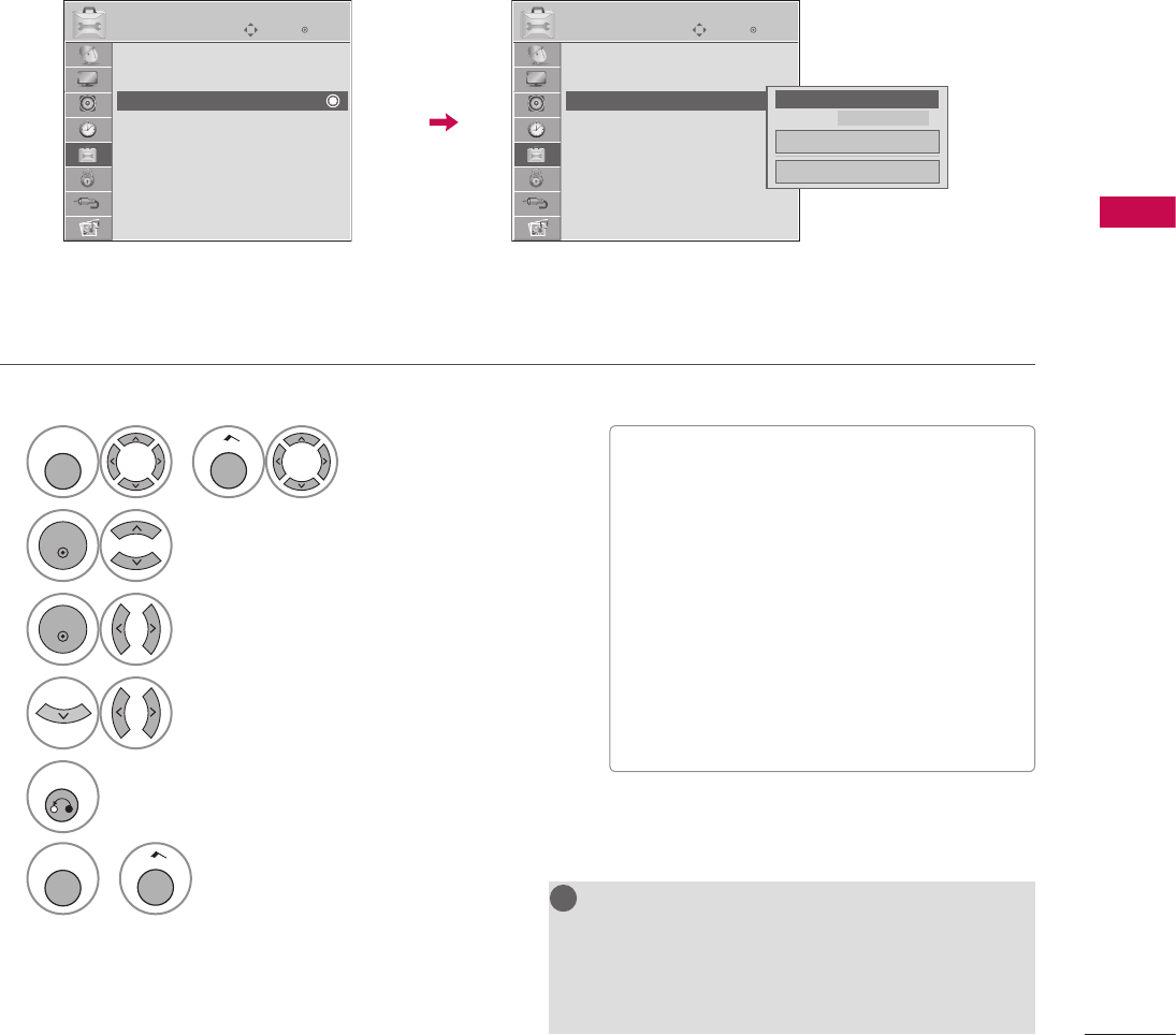
93
SOUND & LANGUAGE CONTROL
1
MENU
or
Home
Select OPTION.
2
ENTER
Select Caption.
3
ENTER
Select On.
4
Select CC1-4 or Text1-4.
5
RETURN
Return to the previous menu.
MENU
or
Home
Return to TV viewing.
Captions are provided to help the hearing impaired watch TV. Select a caption mode for displaying captioning
information if provided on a program. Analog caption displays information at any position on the screen and
is usually the program's dialog. Caption/Text, if provided by the broadcaster, would be available for both
digital and analog channels on the Antenna/Cable. This TV is programmed to memorize the caption/text mode
which was last set when you turned the power off. This function is only available when Caption Mode is set On.
Analog Broadcasting System Captions
NOTE
G Data Broadcasting: For 32/37/42LG710H,
32/37/42/47/55LD650H, 32/37/42LD655H
G Zone: For 32/37/42LD660H,
32/37/42LD665H, 32/37/42/47/55LV555H
!
?
!
?
! !
CAPTION MODE
V When selecting Off, Sub-menus for Analog,
DTV, and Digital Option become disabled.
V CAPTION
The term for the words that scroll across the
bottom of the TV screen; usually the audio
portion of the program provided for the
hearing impaired.
V TEXT
The term for the words that appear in a
large black frame and almost cover the
entire screen; usually messages provided by
the broadcaster.
ὤ㨴㥄
EnterMove
OPTION
Menu Language : English
Audio Language : English
Caption : Off
Set ID : 1
Demo Mode : Off
Data Broadcasting
Zone
EnterMove
OPTION
Menu Language : English
Audio Language : English
Caption : CC1
Set ID : 1
Demo Mode : Off
Data Broadcasting
Zone
F On G
Mode CC1
Digital Option
Close
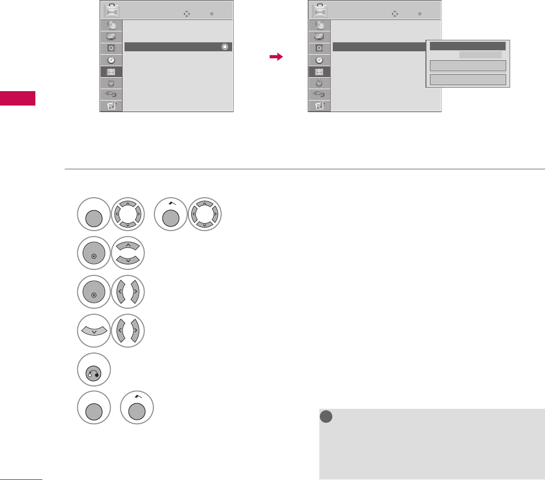
94
SOUND & LANGUAGE CONTROL
SOUND & LANGUAGE CONTROL
Digital Broadcasting System Captions
Choose the language you want the DTV/CADTV Captions to appear in.
Other Languages can be chosen for digital sources only if they are included on the program.
This function in only available when Caption Mode is set On.
NOTE
G Data Broadcasting: For 32/37/42LG710H,
32/37/42/47/55LD650H, 32/37/42LD655H
G Zone: For 32/37/42LD660H,
32/37/42LD665H, 32/37/42/47/55LV555H
!
?
!
?
! !
1
MENU
or
Home
Select OPTION.
2
ENTER
Select Caption.
3
ENTER
Select On.
4
Select CC1-4, Text1-4, or Service1-6.
5
RETURN
Return to the previous menu.
MENU
or
Home
Return to TV viewing.
ὤ㨴㥄
EnterMove
OPTION
Menu Language : English
Audio Language : English
Caption : Off
Set ID : 1
Demo Mode : Off
Data Broadcasting
Zone
EnterMove
OPTION
Menu Language : English
Audio Language : English
Caption : CC1
Set ID : 1
Demo Mode : Off
Data Broadcasting
Zone
F On G
Mode CC1
Digital Option
Close
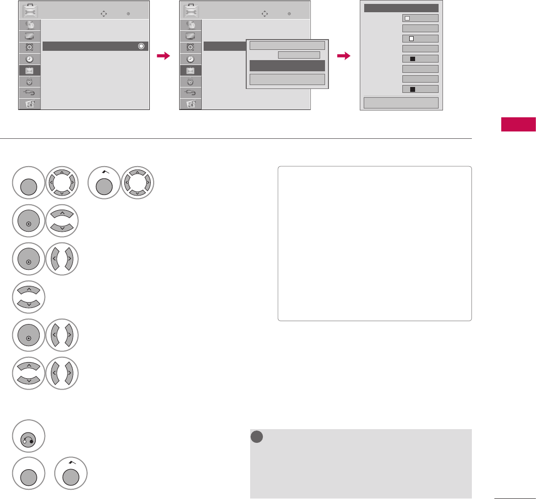
95
SOUND & LANGUAGE CONTROL
1
MENU
or
Home
Select OPTION.
2
ENTER
Select Caption.
3
ENTER
Select On.
4
Select Digital Option.
5
ENTER
Select Custom.
6
Customize the Size, Font, etc., to your preference.
A preview icon is provided at the bottom of the screen,
use it to see the caption language.
7
RETURN
Return to the previous menu.
MENU
or
Home
Return to TV viewing.
Customize the DTV captions that appear on your screen.
This function in only available when Caption Mode is set On.
Caption Option
NOTE
G Data Broadcasting: For 32/37/42LG710H,
32/37/42/47/55LD650H, 32/37/42LD655H
G Zone: For 32/37/42LD660H,
32/37/42LD665H, 32/37/42/47/55LV555H
!
?
!
?
! !
V
Size: Set the word size.
V Font: Select a typeface for the text.
V Text Color: Choose a color for the text.
V Text Opacity: Specify the opacity for the
text color.
V Bg (Background) Color: Select a
background color.
V Bg (Background) Opacity: Select the
opacity for the background color.
V Edge Type: Select an edge type.
V Edge Color: Select a color for the edges.
ὤ㨴㥄
ὤ㨴㥄
EnterMove
OPTION
Menu Language : English
Audio Language : English
Caption : Off
Set ID : 1
Demo Mode : Off
Data Broadcasting
Zone
EnterMove
OPTION
Menu Language : English
Audio Language : English
Caption : CC1
Set ID : 1
Demo Mode : Off
Data Broadcasting
Zone
On
Mode CC1
Digital Option
Close
F Custom G
Size A Standard
Font Font 1
Text Color White
Text Opacity Solid
Bg Color Black
Bg Opacity Solid
Edge Type None
Edge Color Black
Close
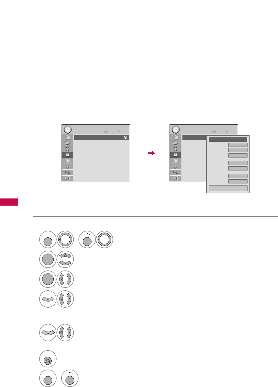
96
TIME SETTING
TIME SETTING
TIME SETTING
Auto Clock Setup
The time is set automatically from a digital channel signal.
The digital channel signal includes information for the current time provided by the broadcasting station.
Set the clock manually if the current time is set incorrectly by the auto clock function.
CLOCK SETTING
1
MENU
or
Home
Select TIME.
2
ENTER
Select Clock.
3
ENTER
Select Auto.
4
Select your viewing area time zone.
• U.S.A: Eastern, Central, Mountain, Pacific, Alaska, or Hawaii.
• Canada: Eastern, Central, Mountain, Pacific, New F.land, or Atlantic.
5
Select Auto, Off, or On
(depending on whether or not your viewing area observes Daylight Saving time).
6
RETURN
Return to the previous menu.
MENU
or
Home
Return to TV viewing.
EnterMove
TIME
Clock
Off Time : Off
On Time : Off
Sleep Timer : Off
Auto Off : On
ὤ㨴㥄
EnterMove
TIME
Clock
Off Time : Off
On Time : Off
Sleep Timer : Off
Auto Off : On
F Auto G
Month 11
Date 27
Year 2011
Hour 10 AM
Minute 10
Time Zone Eastern
Daylight Saving Auto
Close
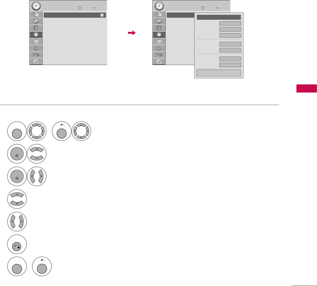
97
TIME SETTING
Manual Clock Setup
If the current time setting is wrong, reset the clock manually.
1
MENU
or
Home
Select TIME.
2
ENTER
Select Clock.
3
ENTER
Select Manual.
4
Select the Year, Month, Date, Hour, or Minutes option.
5
Set the Year, Month, Date, Hour, or Minutes option.
6
RETURN
Return to the previous menu.
MENU
or
Home
Return to TV viewing.
EnterMove
TIME
Clock
Off Time : Off
On Time : Off
Sleep Timer : Off
Auto Off : On
ὤ㨴㥄
EnterMove
TIME
Clock
Off Time : Off
On Time : Off
Sleep Timer : Off
Auto Off : On
F Manual G
Month 11
Date 27
Year 2011
Hour 10 AM
Minute 10
Time Zone Eastern
Daylight Saving Auto
Close
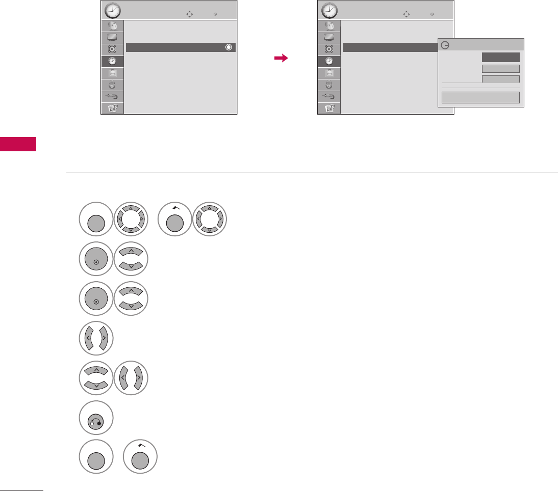
98
TIME SETTING
TIME SETTING
This function operates only if the current time has been set.
The Off Time function overrides the On Time function if they are both set to the same time.
The TV must be in standby mode for the On Time to work.
AUTO ON/OFF TIME SETTING
1
MENU
or
Home
Select TIME.
2
ENTER
Select Off Time or On Time.
3
ENTER
Select Repeat.
4
Select Off, Once, Daily, Mon.~Fri., Mon.~Sat., Sat.~Sun., or Sun..
5
Select and set Hour or Minute.
6
RETURN
Return to the previous menu.
MENU
or
Home
Return to TV viewing.
EnterMove
TIME
Clock
Off Time : Off
On Time : Off
Sleep Timer: Off
Auto Off : On
ὤ㨴㥄
EnterMove
TIME
Clock
Off Time : Off
On Time : 6:30 AM (Once)
Sleep Timer: Off
Auto Off : On
Nov. 27, 2011 10:10 AM
Repeat F Once G
Hour 6 AM
Minute 30
Close
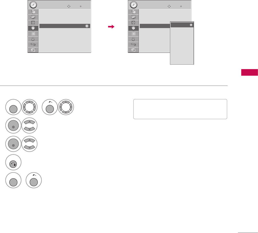
99
TIME SETTING
1
MENU
or
Home
Select TIME.
2
ENTER
Select Sleep Timer.
3
ENTER
Make appropriate adjustments.
4
RETURN
Return to the previous menu.
MENU
or
Home
Return to TV viewing.
The Sleep Timer turns the TV off at the preset time.
Note that this setting is cleared when the TV is turned off.
SLEEP TIMER SETTING
V To cancel the Sleep Timer, select Off.
V Press the SLEEP button repeatedly to select
the number of minutes.
EnterMove
TIME
Clock
Off Time : Off
On Time : Off
Sleep Timer: Off
Auto Off : On
ὤ㨴㥄
EnterMove
TIME
Clock
Off Time : Off
On Time : Off
Sleep Timer: Off
Auto Off : On
Off
10 min.
20 min.
30 min.
60 min.
90 min.
120 min.
180 min.
240 min.
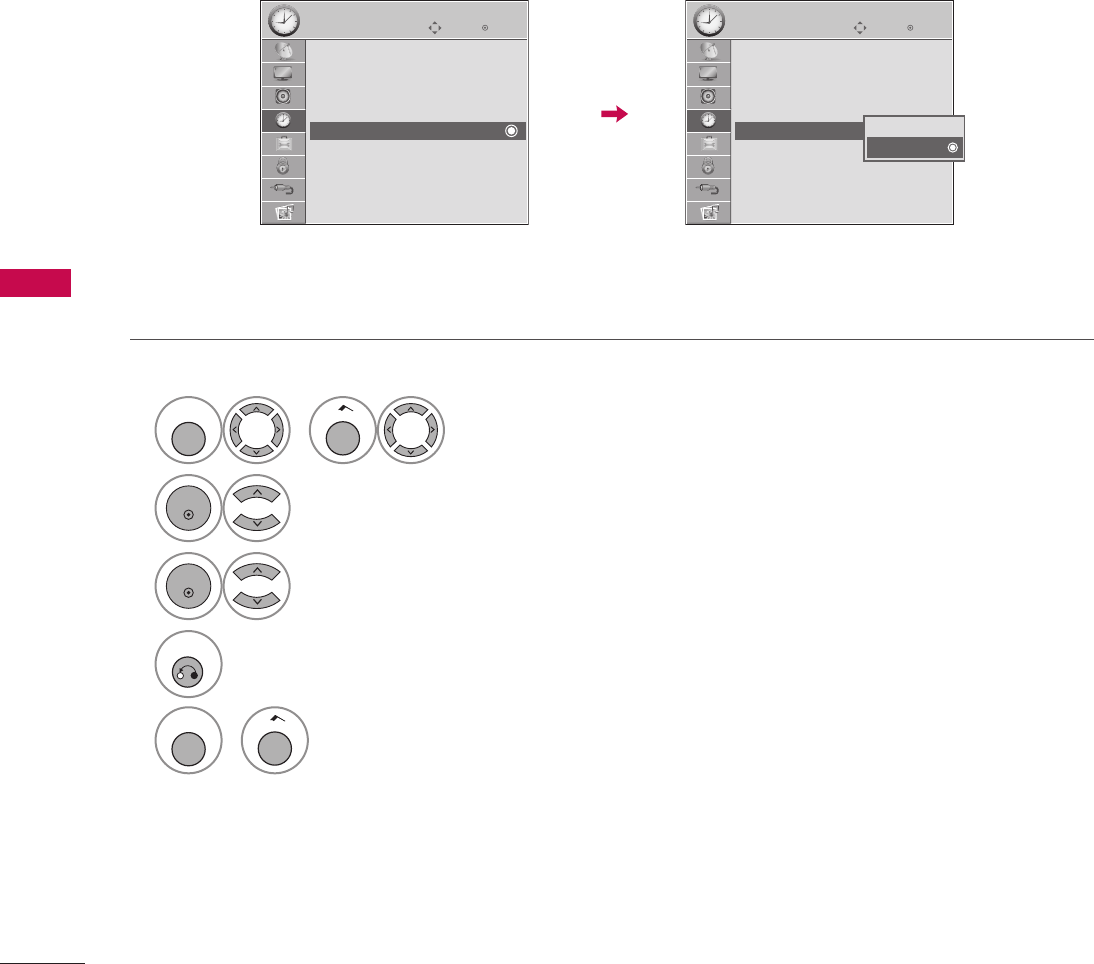
100
TIME SETTING
TIME SETTING
If set to on and there is no input signal, the TV turns off automatically after 15 minutes.
AUTO SHUT-OFF SETTING
1
MENU
or
Home
Select TIME.
2
ENTER
Select Auto Off.
3
ENTER
Select On or Off.
4
RETURN
Return to the previous menu.
MENU
or
Home
Return to TV viewing.
EnterMove
TIME
Clock
Off Time : Off
On Time : Off
Sleep Timer: Off
Auto Off : On
ὤ㨴㥄
EnterMove
TIME
Clock
Off Time : Off
On Time : Off
Sleep Timer: Off
Auto Off : On Off
On

101
PARENTAL CONTROL / RATINGS
PARENTAL CONTROL / RATINGS
Parental Control can be used to block specific channels, ratings and other viewing sources.
The Parental Control Function (V-Chip) is used to block program viewing based on the ratings sent by the
broadcasting station. The default setting is to allow all programs to be viewed. Viewing can be blocked by
choosing the type of the program and the categories. It is also possible to block all program viewing for a time
period. To use this function, the following must be done:
1. Set ratings and categories to be blocked.
2. Specify a password
3. Enable the lock
V-Chip rating and categories
Rating guidelines are provided by broadcasting stations. Most television programs and television movies can be
blocked by TV Rating and/or Individual Categories. Movies that have been shown at the theaters or direct-to-
video movies use the Movie Rating System (MPAA) only.
Ratings for Television programs including made-for-TV movies:
V TV-G (General audience)
V TV-PG (Parental guidance suggested)
V TV-14 (Parents strongly cautioned)
V TV-MA (Mature audience only)
V TV-Y (All children)
V TV-Y7 (Children 7 years older)
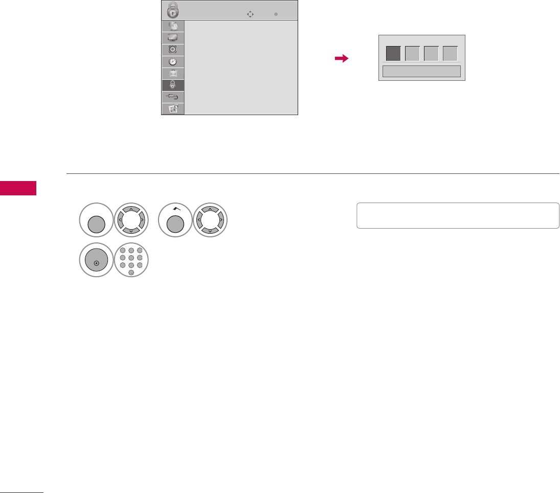
102
PARENTAL CONTROL / RATINGS
PARENTAL CONTROL / RATINGS
1
MENU
or
Home
Select LOCK.
2
ENTER
1 2 3
4 5 6
7 8
0
9
ABC DEF
GHI
WXYZ
TUV
PQRS
MNO
JKL
&@
.:/,
Input the password.
Set up blocking schemes to block specific channels, ratings, and external viewing sources.
A password is required to gain access to this menu.
Setting up Your Password
SET PASSWORD & LOCK SYSTEM
V The TV is set up with the initial password
“0-0-0-0”.
ὤ㨴㥄
EnterMove
LOCK
Lock System : Off
Set Password
Block Channel
Movie Rating
TV Rating-Children
TV Rating-General
Downloadable Rating
Input Block
Enter Password
* * * *
Close
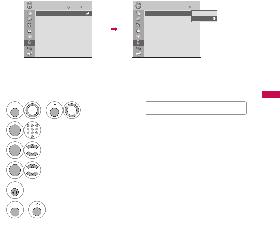
103
PARENTAL CONTROL / RATINGS
Enables or disables the blocking scheme you set up previously.
Lock System
1
MENU
or
Home
Select LOCK.
2
ENTER
1 2 3
4 5 6
7 8
0
9
ABC DEF
GHI
WXYZ
TUV
PQRS
MNO
JKL
&@
.:/,
Input the password.
3
ENTER
Select Lock System.
4
ENTER
Select On or Off.
5
RETURN
Return to the previous menu.
MENU
or
Home
Return to TV viewing.
V When you select On, the Lock System is
enable.
ὤ㨴㥄
EnterMove
LOCK
Lock System : On
Set Password
Block Channel
Movie Rating
TV Rating-Children
TV Rating-General
Downloadable Rating
Input Block
Off
On
EnterMove
LOCK
Lock System : Off
Set Password
Block Channel
Movie Rating
TV Rating-Children
TV Rating-General
Downloadable Rating
Input Block
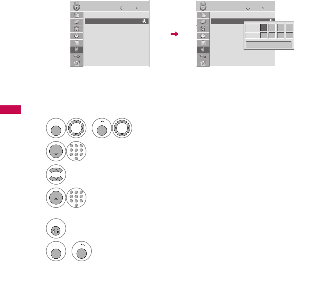
104
PARENTAL CONTROL / RATINGS
PARENTAL CONTROL / RATINGS
Set up blocking schemes to block specific channels, ratings, and external viewing sources.
A password is required to gain access to this menu.
Set Password
1
MENU
or
Home
Select LOCK.
2
ENTER
1 2 3
4 5 6
7 8
0
9
ABC DEF
GHI
WXYZ
TUV
PQRS
MNO
JKL
&@
.:/,
Input the password.
3
Select Set Password.
4
ENTER
1 2 3
4 5 6
7 8
0
9
ABC DEF
GHI
WXYZ
TUV
PQRS
MNO
JKL
&@
.:/,
Choose any 4 digits for your new password.
As soon as the 4 digits are entered, re-enter the same 4 digits on the Confirm.
5
RETURN
Return to the previous menu.
MENU
or
Home
Return to TV viewing.
ὤ㨴㥄
EnterMove
LOCK
Lock System : Off
Set Password
Block Channel
Movie Rating
TV Rating-Children
TV Rating-General
Downloadable Rating
Input Block
New *** *
Confirm * * * *
Close
EnterMove
LOCK
Lock System : Off
Set Password
Block Channel
Movie Rating
TV Rating-Children
TV Rating-General
Downloadable Rating
Input Block
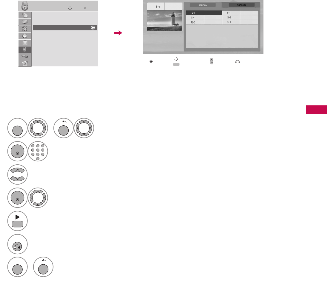
105
PARENTAL CONTROL / RATINGS
Blocks any channels that you do not want to watch or that you do not want your children to watch.
CHANNEL BLOCKING
1
MENU
or
Home
Select LOCK.
2
ENTER
1 2 3
4 5 6
7 8
0
9
ABC DEF
GHI
WXYZ
TUV
PQRS
MNO
JKL
&@
.:/,
Input the password.
3
Select Block Channel.
4
ENTER
Select a channel to block or unblock.
5
Block or unblock a channel.
6
RETURN
Return to the previous menu.
MENU
or
Home
Return to TV viewing.
EnterMove
LOCK
Lock System : Off
Set Password
Block Channel
Movie Rating
TV Rating-Children
TV Rating-General
Downloadable Rating
Input Block
ὤ㨴㥄
Ch. Change
ὤ㨴㥄
Navigation CH
ὤ㨴㥄
ὤ㨴㥄
Page Change
ὤ㨴㥄
Previous
Block/Unblock
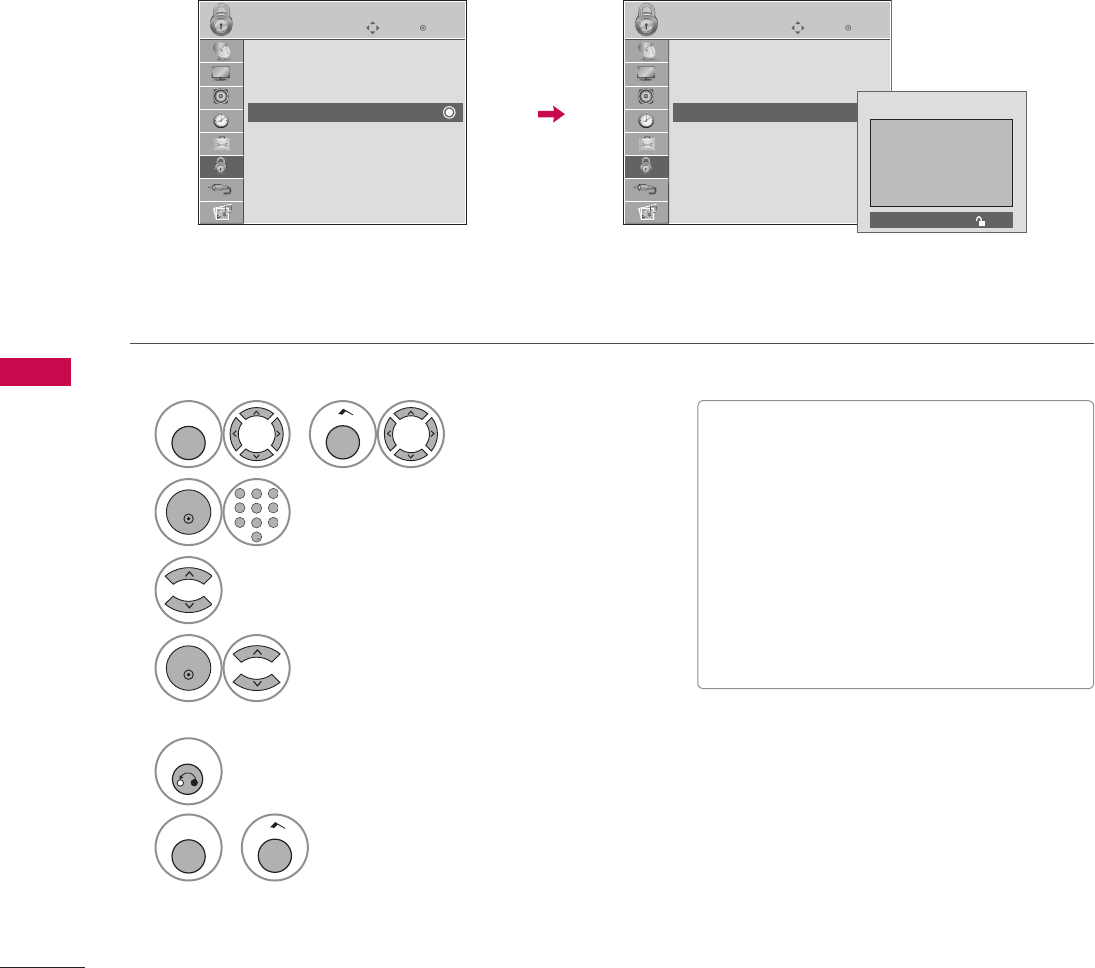
106
PARENTAL CONTROL / RATINGS
PARENTAL CONTROL / RATINGS
1
MENU
or
Home
Select LOCK.
2
ENTER
1 2 3
4 5 6
7 8
0
9
ABC DEF
GHI
WXYZ
TUV
PQRS
MNO
JKL
&@
.:/,
Input the password.
3
Select Movie Rating.
4
ENTER
Select G, PG, PG-13, R, NC-17, X,
or Blocking Off.
5
RETURN
Return to the previous menu.
MENU
or
Home
Return to TV viewing.
Movie Rating (MPAA) - For USA
Blocks movies according to the movie ratings limits specified, so children cannot view certain movies. You can
set the ratings limit by blocking out all the movies with the ratings above a specified level. Keep in mind that
the movie ratings limit only applies to movies shown on TV, not TV programs, such as soap operas.
MOVIE & TV RATING
V G (General audience)
V PG (Parental guidance suggested)
V PG-13 (Parents strongly cautioned)
V R (Restricted)
V NC-17 (No one 17 and under admitted)
V X (Adult only)
V Blocking Off (Permits all programs)
V If you set PG-13: G and PG movies will be
available, PG-13, R, NC-17 and X will be
blocked.
ὤ㨴㥄
EnterMove
LOCK
Lock System : Off
Set Password
Block Channel
Movie Rating
TV Rating-Children
TV Rating-General
Downloadable Rating
Input Block
EnterMove
LOCK
Lock System : Off
Set Password
Block Channel
Movie Rating
TV Rating-Children
TV Rating-General
Downloadable Rating
Input Block
Blocking off : Permits all programs
G
PG
PG-13
R
NC-17
X
Blocking Off
ὤ㨴㥄
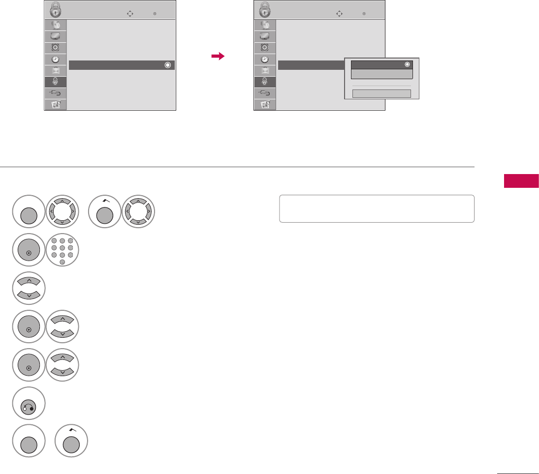
107
PARENTAL CONTROL / RATINGS
1
MENU
or
Home
Select LOCK.
2
ENTER
1 2 3
4 5 6
7 8
0
9
ABC DEF
GHI
WXYZ
TUV
PQRS
MNO
JKL
&@
.:/,
Input the password.
3
Select TV Rating-Children.
4
ENTER
Select Age or Fantasy Violence.
5
ENTER
Select block options.
6
RETURN
Return to the previous menu.
MENU
or
Home
Return to TV viewing.
TV Rating Children - For USA
Prevents children from watching certain children's TV programs, according to the ratings limit set. The children
rating does not apply to other TV programs. Unless you block certain TV programs intended for mature audi-
ences in the TV Rating - sub menu, your children can view those programs.
V
Age (applies to TV-Y, TV-Y7)
V Fantasy Violence (applies to TV-Y7)
ὤ㨴㥄
EnterMove
LOCK
Lock System : Off
Set Password
Block Channel
Movie Rating
TV Rating-Children
TV Rating-General
Downloadable Rating
Input Block
EnterMove
LOCK
Lock System : Off
Set Password
Block Channel
Movie Rating
TV Rating-Children
TV Rating-General
Downloadable Rating
Input Block
Age
Fantasy Violence
Close
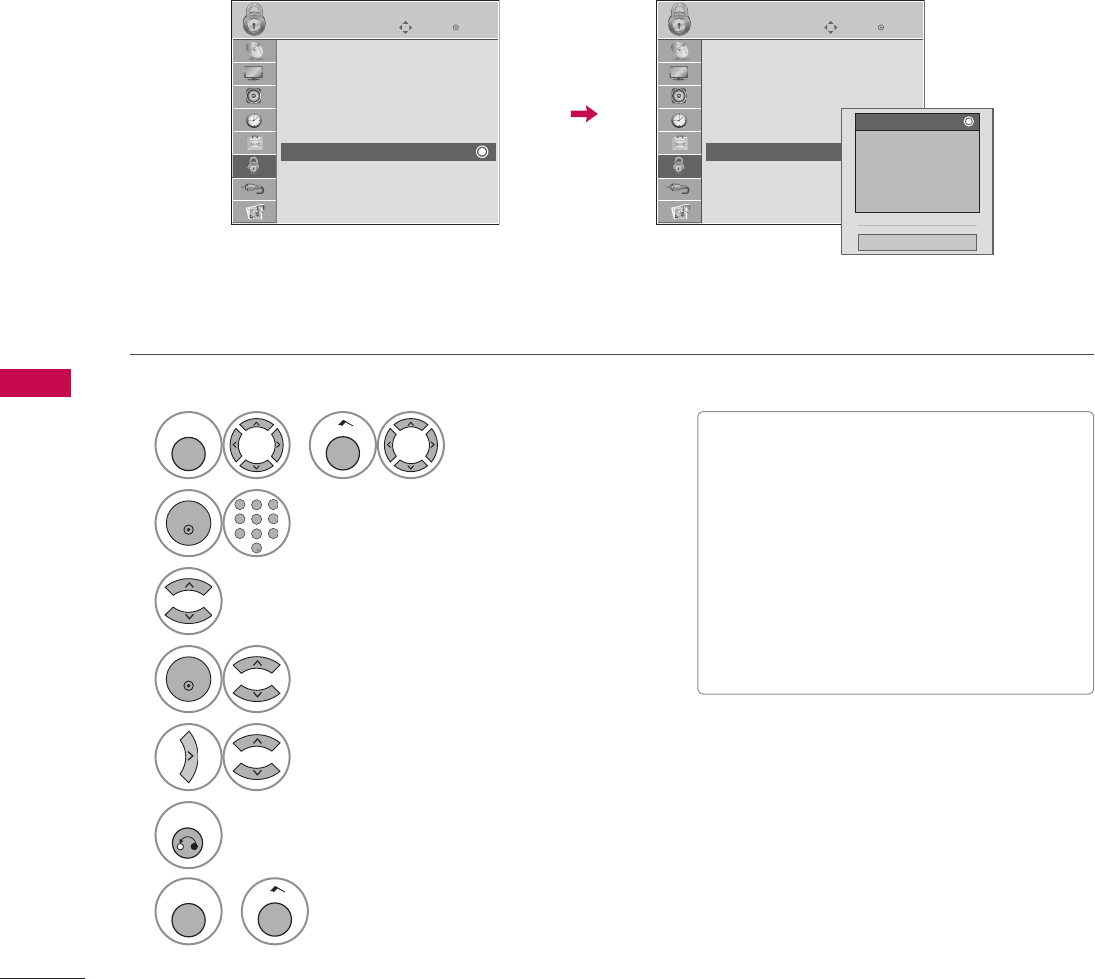
108
PARENTAL CONTROL / RATINGS
PARENTAL CONTROL / RATINGS
TV Rating General - For USA
Based on the ratings, blocks certain TV programs that you and your family do not want to view.
1
MENU
or
Home
Select LOCK.
2
ENTER
1 2 3
4 5 6
7 8
0
9
ABC DEF
GHI
WXYZ
TUV
PQRS
MNO
JKL
&@
.:/,
Input the password.
3
Select TV Rating-General.
4
ENTER
Select Age, Dialogue, Language, Sex or Violence.
5
Select block options.
6
RETURN
Return to the previous menu.
MENU
or
Home
Return to TV viewing.
V Age
(applies to TV-G,TV-PG,TV-14,TV-MA).
V Dialogue - sexual dialogue
(applies to TV-PG, TV-14).
V Language - adult language
(applies to TV-PG, TV-14, TV-MA).
V Sex - sexual situations
(applies to TV-PG, TV-14, TV-MA).
V Violence
(applies to TV-PG, TV-14, TV-MA).
ὤ㨴㥄
EnterMove
LOCK
Lock System : Off
Set Password
Block Channel
Movie Rating
TV Rating-Children
TV Rating-General
Downloadable Rating
Input Block
EnterMove
LOCK
Lock System : Off
Set Password
Block Channel
Movie Rating
TV Rating-Children
TV Rating-General
Downloadable Rating
Input Block
Age
Dialogue
Language
Sex
Violence
Close
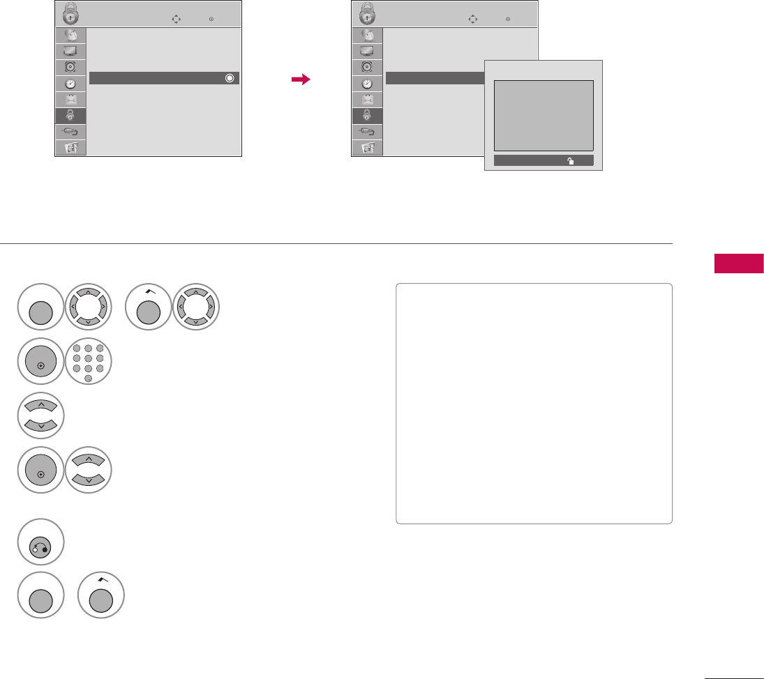
109
PARENTAL CONTROL / RATINGS
TV Rating English - For CANADA
Selecting Canadian English rating system.
1
MENU
or
Home
Select LOCK.
2
ENTER
1 2 3
4 5 6
7 8
0
9
ABC DEF
GHI
WXYZ
TUV
PQRS
MNO
JKL
&@
.:/,
Input the password.
3
Select TV Rating-English.
4
ENTER
Select E, C, C8+, G, PG, 14+, 18+,
or Blocking Off.
5
RETURN
Return to the previous menu.
MENU
or
Home
Return to TV viewing.
V If TV Rating-English or TV Rating-French
is locked, enter the password to unlocked it
temporarily.
V E (Exempt)
V C (Children)
V C8+ (Children eight years and older)
V G (General programming, suitable for all
audiences)
V PG (Parental Guidance)
V 14+ (Viewers 14 years and older)
V 18+ (Adult programming)
V Blocking Off (Permits all programs)
ὤ㨴㥄
EnterMove
LOCK
Lock System : Off
Set Password
Block Channel
TV Rating-English
TV Rating-French
Downloadable Rating
Input Block
EnterMove
LOCK
Lock System : Off
Set Password
Block Channel
TV Rating-English
TV Rating-French
Downloadable Rating
Input Block
Blocking off : Permits all programs
E
C
C8+
G
PG
14+
18+
Blocking Off
ὤ㨴㥄
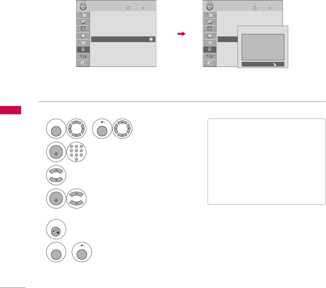
110
PARENTAL CONTROL / RATINGS
PARENTAL CONTROL / RATINGS
TV Rating French - For CANADA
Selecting Canadian French rating system.
1
MENU
or
Home
Select LOCK.
2
ENTER
1 2 3
4 5 6
7 8
0
9
ABC DEF
GHI
WXYZ
TUV
PQRS
MNO
JKL
&@
.:/,
Input the password.
3
Select TV Rating-French.
4
ENTER
Select E, G, 8ans+, 13ans+, 16ans+,
18ans+, or Blocking off.
5
RETURN
Return to the previous menu.
MENU
or
Home
Return to TV viewing.
V E (Exempt)
V G (General)
V 8ans+ (General-Not convenient for little
children)
V 13ans+ (Not convenient for children of 13
years and younger)
V 16ans+ (Not convenient for children of 16
years and younger)
V 18ans+ (This programs is only for adults)
V Blocking off (Permits all programs)
ὤ㨴㥄
EnterMove
LOCK
Lock System : Off
Set Password
Block Channel
TV Rating-English
TV Rating-French
Downloadable Rating
Input Block
EnterMove
LOCK
Lock System : Off
Set Password
Block Channel
TV Rating-English
TV Rating-French
Downloadable Rating
Input Block
Blocking off : Permits all programs
E
G
8ans+
13ans+
16ans+
18ans+
Blocking Off
ὤ㨴㥄
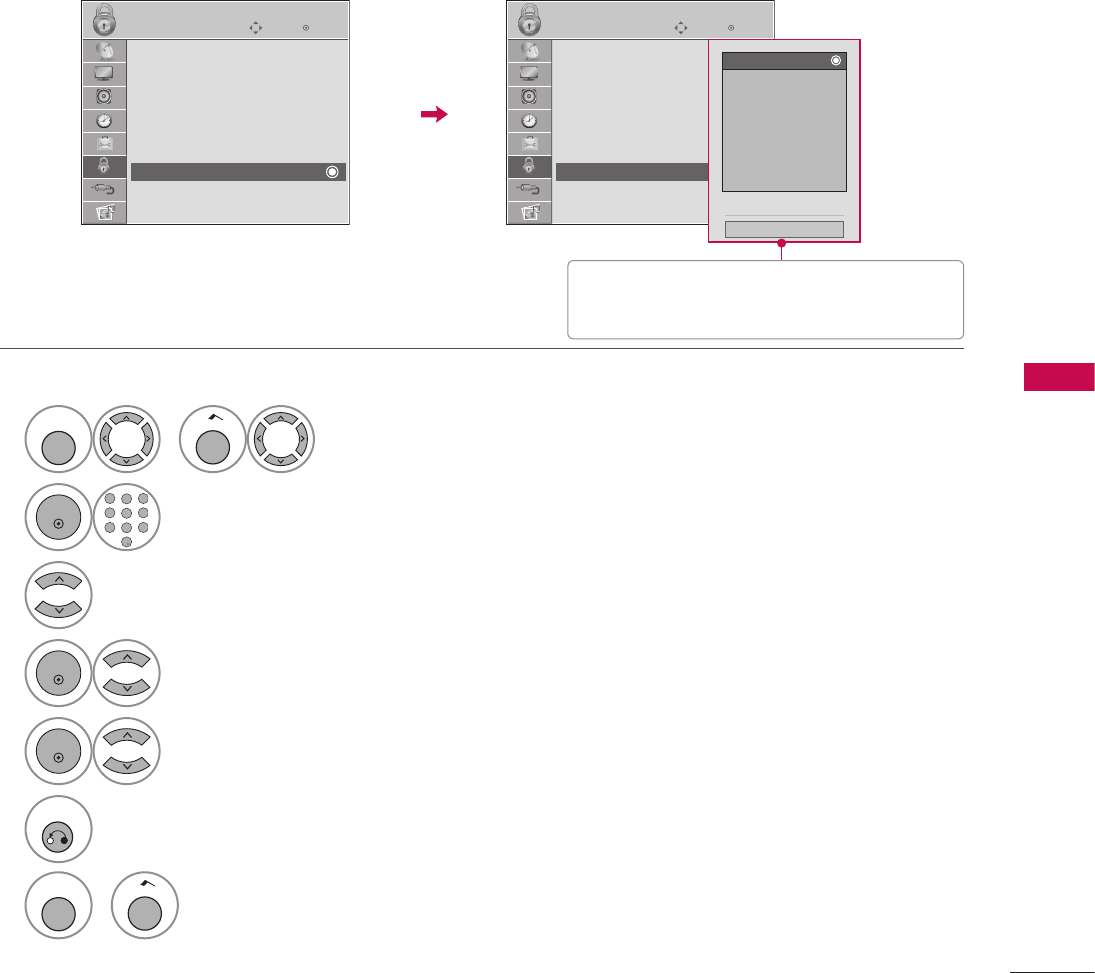
111
PARENTAL CONTROL / RATINGS
This function is available only for digital channels.
This function operates only when TV has received Region5 Rating data.
DOWNLOADABLE RATING
1
MENU
or
Home
Select LOCK.
2
ENTER
1 2 3
4 5 6
7 8
0
9
ABC DEF
GHI
WXYZ
TUV
PQRS
MNO
JKL
&@
.:/,
Input the password.
3
Select Downloadable Rating.
4
ENTER
Select desired Downloadable Rating option.
5
ENTER
Select desired option and block it.
6
RETURN
Return to the previous menu.
MENU
or
Home
Return to TV viewing.
ὤ㨴㥄
EnterMove
LOCK
Lock System : Off
Set Password
Block Channel
Movie Rating
TV Rating-Children
TV Rating-General
Downloadable Rating
Input Block
EnterMove
LOCK
Lock System : Off
Set Password
Block Channel
Movie Rating
TV Rating-Children
TV Rating-General
Downloadable Rating
Input Block
D
Humor
Sport
Cruelty
Language
Sadness
Genre
Age
E
Close
V
Based on rating table, your TV's OSD (On
Screen Display) may differ slightly from
what is shown in this manual.
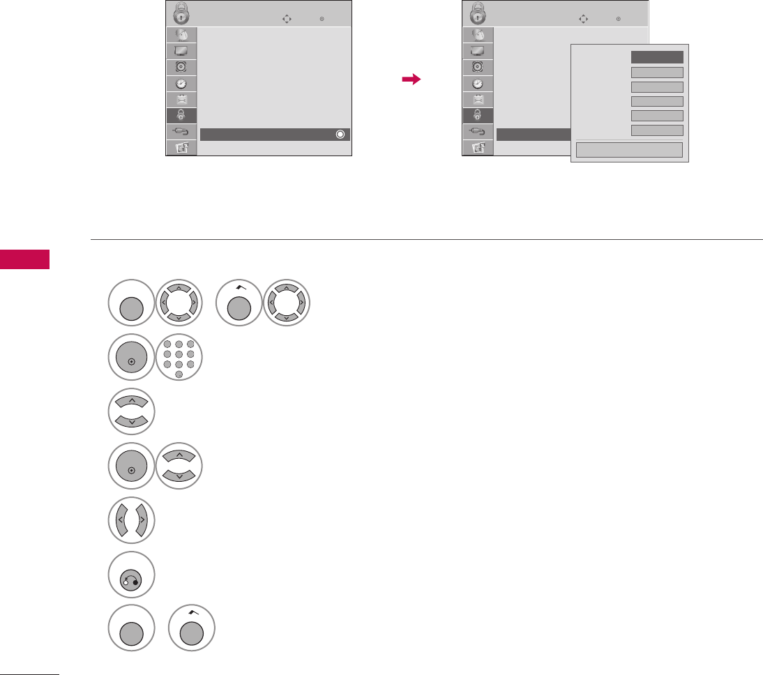
112
PARENTAL CONTROL / RATINGS
PARENTAL CONTROL / RATINGS
Enables you to block an input.
EXTERNAL INPUT BLOCKING
1
MENU
or
Home
Select LOCK.
2
ENTER
1 2 3
4 5 6
7 8
0
9
ABC DEF
GHI
WXYZ
TUV
PQRS
MNO
JKL
&@
.:/,
Input the password.
3
Select Input Block.
4
ENTER
Select input source.
5
Select On or Off.
6
RETURN
Return to the previous menu.
MENU
or
Home
Return to TV viewing.
ὤ㨴㥄
EnterMove
LOCK
Lock System : Off
Set Password
Block Channel
Movie Rating
TV Rating-Children
TV Rating-General
Downloadable Rating
Input Block
EnterMove
LOCK
Lock System : Off
Set Password
Block Channel
Movie Rating
TV Rating-Children
TV Rating-General
Downloadable Rating
Input Block
AV1 F Off G
AV2 Off
Component Off
RGB-PC Off
HDMI1 Off
HDMI2 Off
Close

113
APPENDIX
APPENDIX
TROUBLESHOOTING
Video Problems
No picture &No sound
V Check whether the product is turned on.
V Try another channel. The problem may be with the broadcast.
V Is the power cord inserted into wall power outlet?
V Check your antenna direction and/or location.
V
Test the wall power outlet, plug another product’s power cord into the outlet
where the product’s power cord was plugged in.
Picture appears slowly
after switching on
V
This is normal, the image is muted during the product startup process. Please
contact your service center, if the picture has not appeared after five minutes.
No or poor color
or poor picture
V Adjust Color in menu option.
V
Try unplugging any others electronics that are near by to see if interference
is causing the problem.
V Try another channel. The problem may be with the broadcast.
V Are the video cables installed properly?
V Activate any function to restore the brightness of the picture.
Horizontal/vertical bars
or picture shaking
V Check for local interference such as an electrical appliance or power tool.
Poor reception on
some channels
V Station or cable product experiencing problems, tune to another station.
V Station signal is weak, reorient antenna.
V Check for sources of possible interference.
Lines or streaks
in pictures
V Check antenna (Change the direction of the antenna).
No picture
when connecting HDMI
V
If the HDMI cables don’t support High Speed HDMI, it can cause flickers or
no screen display. In this case use the latest cables that support High Speed
HDMI.
Abnormal Operation
The remote control
doesn’t work
V
Check to see if there is any object between the product and the remote control
causing obstruction. Ensure you are pointing the remote control directly at the
TV.
V Ensure that the batteries are installed with correct polarity (+ to +, - to -).
V Ensure that the correct remote operating mode is set: TV, VCR etc.
V Install new batteries.
Power is suddenly
turned off
V Is the sleep timer set?
V Check the power control settings. Power interrupted.

114
APPENDIX
APPENDIX
Audio Problems
Picture OK but No sound
V Press the VOL or VOLUME button.
V Sound muted? Press the MUTE button.
V Try another channel. The problem may be with the broadcast.
V Are the audio cables installed properly?
No output from one
of the speakers
V Adjust Balance in menu option.
Unusual sound from
inside the product
V
A change in ambient humidity or temperature may result in an unusual noise
when the product is turned on or off and does not indicate a fault with the
product.
No sound
when connecting
HDMI or USB
V Check High Speed HDMI cable.
V Check USB cable over version 2.0.
V Use normal MP3 file. *This feature is not available for all models.
PC Mode Problems
The signal is out of range
V Adjust resolution, horizontal frequency, or vertical frequency.
V Check the input source.
Vertical bar or stripe on
background
& Horizontal Noise
& Incorrect position
V Work the Auto configure or adjust clock, phase, or H/V position. (Option)
Screen color is unstable
or single color
V Check the signal cable.
V Update video card drivers.

115
APPENDIX
Early malfunctions can be prevented. Careful and regular cleaning can extend the amount of time you can
enjoy your new TV.
Caution: Be sure to turn the power off and unplug the power cord before you begin any cleaning.
Cleaning the Screen
1 Here’s a great way to keep the dust off your screen for a while. Wet a soft cloth in a mixture of lukewarm
water and a little fabric softener or dish washing detergent. Wring the cloth until it’s almost dry, and then
use it to wipe the screen.
2 Make sure the excess water is off the screen, and then let it air-dry before you turn on your TV.
WARNING
G Do not use window/glass cleaner or anything with ammonia to clean the screen.
!
?
!
?
! !
Cleaning the Cabinet
V To remove dirt or dust, wipe the cabinet with a soft, dry, lint-free cloth.
V Please be sure not to use a wet cloth.
Extended Absence
CAUTION
G If you expect to leave your TV dormant for a long time (such as a vacation), it’s a good idea to unplug the
power cord to protect against possible damage from lightning or power surges.
!
?
!
?
! !
MAINTENANCE
116
APPENDIX
APPENDIX
PRODUCT SPECIFICATIONS
V The specifications shown above may be changed without prior notice for quality improvement.
MODELS 32LG710H
(32LG710H-UA)
37LG710H
(37LG710H-UA)
42LG710H
(42LG710H-UA)
Dimensions
(Width x
Height x
Depth)
With stand 797 x 597 x 232.5 mm
(31.3 x 23.5 x 9.15 inch)
918.6 x 684.8 x 293.4 mm
(36.1 x 26.9 x 11.5 inch)
1026.2 x 734.1 x 293.4 mm
(40.4 x 28.9 x 11.5 inch)
Without stand 797 x 558.7 x 109.3 mm
(31.3 x 21.9 x 4.3 inch)
918.6 x 635.8 x 111.7 mm
(36.1 x 25.0 x 4.39 inch)
1026.2 x 687.9 x 111.8 mm
(40.4 x 27.0 x 4.4 inch)
Weight
With stand 12.89 kg (28.41 lbs) 17.97 kg (39.61 lbs) 21.10 kg (46.51 lbs)
Without stand 11.41 kg (25.15 lbs) 15.41 kg (33.97 lbs) 18.48 kg (40.74 lbs)
Current Value /
Power Consumption 1.5A / 150W 1.8A / 180W 2.3A / 230W
Cable Card
MPI card
(Width x
Height x
Depth)
3.1 x 0.9 x 6.3 inch
80.0(+0.6/-0.2) x less than 23.0(including pcb thickness)
x less than 162.0(excluding cover thickness) mm
Card Bracket
Cover
(Width x
Height )
3.7 x 1.1 inch
94.7(±0.5) x 28.3(±0.5) mm
Power requirement
Television System
Program Coverage
External Antenna Impedance
AC100-240V ~50/60Hz
NTSC-M, ATSC, 64 & 256 QAM
VHF 2-13, UHF 14-69, CATV 1-135, DTV 2-69, CADTV 1-135
75 Ω
Environment
condition
Operating
Temperature 32 ~104°F (0 ~ 40°C)
Operating
Humidity Less than 80%
Storage
Temperature -4 ~140°F (-20 ~ 60°C)
Storage
Humidity Less than 85%
117
APPENDIX
MODELS 32LD650H (32LD650H-UA)
32LD655H (32LD655H-UA)
37LD650H (37LD650H-UA)
37LD655H (37LD655H-UA)
Dimensions
(Width x
Height x
Depth)
With stand 797.0 mm x 557.7 mm x 207.0 mm
(31.3 inch x 21.9 inch x 8.1 inch)
916.0 mm x 626.0 mm x 261.0 mm
(36.0 inch x 24.6 inch x 10.2 inch)
Without stand 797.0 mm x 495.0 mm x 97.1 mm
(31.3 inch x 19.4 inch x 3.8 inch)
916.0 mm x 560.0 mm x 88.9 mm
(36.0 inch x 22.0 inch x 3.5 inch)
Weight
With stand 11.1 kg (24.4 lbs) 14.6 kg (32.1 lbs)
Without stand 9.4 kg (20.7 lbs) 12.0 kg (26.4 lbs)
Current Value / Power Consumption 1.5A / 150W 1.7A / 170W
MODELS 42LD650H (42LD650H-UA)
42LD655H (42LD655H-UA) 47LD650H (47LD650H-UA)
Dimensions
(Width x
Height x
Depth)
With stand 1024.0 mm x 686.6 mm x 261.0 mm
(40.3 inch x 27.0 inch x 10.2 inch)
1137.0 mm x 758.0 mm x 270.0 mm
(44.7 inch x 29.8 inch x 10.6 inch)
Without stand 1024.0 mm x 621.0 mm x 87.1 mm
(40.3 inch x 24.4 inch x 3.4 inch)
1137.0 mm x 685.0 mm x 76.8 mm
(44.7 inch x 26.9 inch x 3.0 inch)
Weight
With stand 17.7 kg (39.0 lbs) 20.3 kg (44.7 lbs)
Without stand 15.1 kg (33.2 lbs) 18.3 kg (40.3 lbs)
Current Value / Power Consumption 2.1A / 210W 2.5A / 250W
MODELS 55LD650H (55LD650H-UA)
Dimensions
(Width x
Height x
Depth)
With stand 1329.0 mm x 872.0 mm x 330.0 mm
(52.3 inch x 34.3inch x 12.9 inch)
Without stand 1329.0 mm x 796.0 mm x 96.5 mm
(52.3 inch x 31.3 inch x 3.7 inch)
Weight
With stand 33.0 kg (72.7 lbs)
Without stand 29.8 kg (65.6 lbs)
Current Value / Power Consumption 3.4A / 340W
Power requirement
Television System
Program Coverage
External Antenna Impedance
AC100-240V ~50/60Hz
NTSC-M, ATSC, 64 & 256 QAM
VHF 2-13, UHF 14-69, CATV 1-135, DTV 2-69, CADTV 1-135
75 Ω
Environment
condition
Operating
Temperature
Operating Humidity
32 ~104°F (0 ~ 40°C)
Less than 80%
Storage Temperature
Storage Humidity
-4 ~140°F (-20 ~ 60°C)
Less than 85%
V The specifications shown above may be changed without prior notice for quality improvement.
118
APPENDIX
APPENDIX
V The specifications shown above may be changed without prior notice for quality improvement.
MODELS 32LD660H (32LD660H-UA)
32LD665H (32LD665H-UA)
Dimensions
(Width x
Height x
Depth)
With stand 797.0 mm x 557.7 mm x 207.0 mm
(31.3 inch x 21.9 inch x 8.1 inch)
Without stand 797.0 x 495.0 x 97.1 mm
(31.3 inch x 19.4 inch x 3.8 inch)
Weight
With stand 11.1 kg (24.4 lbs)
Without stand 9.4 kg (20.7 lbs)
Current Value / Power Consumption 1.2A / 120W
MODELS 37LD660H (37LD660H-UA)
37LD665H (37LD665H-UA)
Dimensions
(Width x
Height x
Depth)
With stand 916.0 mm x 626.0 mm x 261.0 mm
(36.0 inch x 24.6 inch x 10.2 inch)
Without stand 916.0 mm x 560.0 mm x 88.9 mm
(36.0 inch x 22.0 inch x 3.5 inch)
Weight
With stand 14.6 kg (32.1 lbs)
Without stand 12.0 kg (26.4 lbs)
Current Value / Power Consumption 1.7A / 170W
MODELS 42LD660H (42LD660H-UA)
42LD665H (42LD665H-UA)
Dimensions
(Width x
Height x
Depth)
With stand 1024.0 mm x 686.6 mm x 261.0 mm
(40.3 inch x 27.0 inch x 10.2 inch)
Without stand 1024.0 mm x 621.0 mm x 87.1 mm
(40.3 inch x 24.4 inch x 3.4 inch)
Weight
With stand 17.7 kg (39.0 lbs)
Without stand 15.1 kg (33.2 lbs)
Current Value / Power Consumption 1.9A / 190W
Power requirement
Television System
Program Coverage
External Antenna Impedance
AC100-240V ~50/60Hz
NTSC-M, ATSC, 64 & 256 QAM
VHF 2-13, UHF 14-69, CATV 1-135, DTV 2-69, CADTV 1-135
75 Ω
Environment
condition
Operating
Temperature
Operating Humidity
32 ~104°F (0 ~ 40°C)
Less than 80%
Storage Temperature
Storage Humidity
-4 ~140°F (-20 ~ 60°C)
Less than 85%
119
APPENDIX
MODELS 32LV555H (32LV555H-UA) 37LV555H (37LV555H-UA)
Dimensions
(Width x
Height x
Depth)
With stand 776.0 mm x 545.59 mm x 260.8 mm
(30.5 inch x 21.4 inch x 10.2 inch)
896 mm x 610.9 mm x 260.8 mm
(35.7 inch x 24.0 inch x 10.2 inch)
Without stand 776.0 mm x 485.0 mm x 34.9 mm
(30.5 inch x 19.0 inch x 1.3 inch)
896 mm x 553 mm x 34.9 mm
(35.2 inch x 21.7 inch x 1.3 inch)
Weight
With stand 12.4 kg (27.3 lbs) 13.5 kg (29.7 lbs)
Without stand 9.7 kg (21.3 lbs) 10.8 kg (23.8 lbs)
Current Value / Power Consumption 0.8A / 80W 1.0A / 100W
MODELS 42LV555H (42LV555H-UA) 47LV555H (47LV555H-UA)
Dimensions
(Width x
Height x
Depth)
With stand 1012.0 mm x 671.0 mm x 260.8 mm
(39.8 inch x 26.4 inch x 10.2 inch)
1121.0 mm x 746.0 mm x 256.0 mm
(44.1 inch x 29.3 inch x 10.0 inch)
Without stand 1012.0 mm x 617.0 mm x 29.9 mm
(39.8 inch x 24.2 inch x 1.1 inch)
1121.0 mm x 678.0 mm x 29.9 mm
(44.1 inch x 26.6 inch x 1.1 inch)
Weight
With stand 15.9 kg (35.0 lbs) 20.7 kg (45.6 lbs)
Without stand 13.2 kg (29.1 lbs) 18.4 kg (40.5 lbs)
Current Value / Power Consumption 1.4A / 140W 1.5A / 150W
MODELS 55LV555H (55LV555H-UA)
Dimensions
(Width x
Height x
Depth)
With stand 1298.0 mm x 849.0 mm x 338.0 mm
(51.1 inch x 33.4 inch x 13.3 inch)
Without stand 1298.0 mm x 778.0 mm x 29.9 mm
(51.1 inch x 30.6 inch x 1.1 inch)
Weight
With stand 25.8 kg (56.8 lbs)
Without stand 21.7 kg (47.8 lbs)
Current Value / Power Consumption 1.7A / 170W
Power requirement
Television System
Program Coverage
External Antenna Impedance
AC120V ~50 / 60 Hz
NTSC-M, ATSC, 64 & 256 QAM
VHF 2-13, UHF 14-69, CATV 1-135, DTV 2-69, CADTV 1-135
75 Ω
Environment
condition
Operating
Temperature
Operating Humidity
32 ~104°F (0 ~ 40°C)
Less than 80%
Storage Temperature
Storage Humidity
-4 ~140°F (-20 ~ 60°C)
Less than 85%
V The specifications shown above may be changed without prior notice for quality improvement.

120
APPENDIX
APPENDIX
The provided universal remote control can be programmed to operate most remote-controllable devices.
Note that the remote may not control all models of other brands.
Programming a code into a remote mode
1 Testing your remote control.
To find out whether your remote control can operate other components without programming, turn on a
component such as a STB(Set-Top Box) and press the corresponding mode button (such as a STB) on the
remote control, while pointing at the component. Test the POWER and CH
ὤ㨴㥄
ὤ㨴㥄
buttons to see if the
component responds correctly. If the component does not operate correctly, the remote control requires
programming to operate the device.
2 Turn on the component to be programmed, then press the corresponding mode button (such as STB) on
the remote control. The remote control button of the desired device is illuminated.
3 Press the MENU and MUTE buttons simultaneously, and the remote control is ready to be programmed
with the code.
4 Enter a code number using the number buttons on the remote control. Programming code numbers for the
corresponding component can be found on the following pages. If the code is correct, the device will turn
off.
5 Press the MENU button to store the code.
6 Test the remote control functions to see if the component responds correctly. If not, repeat from step 2.
PROGRAMMING THE REMOTE CONTROL

121
APPENDIX
Remote Control Code
VCR
Brand Codes Brand Codes Brand Codes
AIWA 034 MAGIN 040 SAMSUNG 032 040 102 104
105 107 109 112
113 115 120 122
125
AKAI 016 043 046 124
125 146
MAGNAVOX 031 033 034 041
067 068
AMPRO 072 MARANTZ 012 031 033 067
069
ANAM 031 033 103 SANSUI 022 043 048 135
AUDIO DYNAMICS 012 023 039 043 MARTA 101 SANYO 003 007 010 014
102 134
BROKSONIC 035 037 129 MATSUI 027 030
CANON 028 031 033 MEI 031 033 SCOTT 017 037 112 129
131
CAPEHART 108 MEMOREX 003 010 014 031
033 034 053 072
101 102 134 139
CRAIG 003 040 135 SEARS 003 008 009 010
013 014 017 020
031 042 073 081
101
CURTIS MATHES 031 033 041
DAEWOO 005 007 010 064
065 108 110 111
112 116 117 119
MGA 045 046 059
MINOLTA 013 020
MITSUBISHI 013 020 045 046
049 051 059 061
151
SHARP 031 054 149
DAYTRON 108 SHINTOM 024
DBX 012 023 039 043 SONY 003 009 031 052
056 057 058 076
077 078 149
DYNATECH 034 053 MTC 034 040
ELECTROHOME 059 MULTITECH 024 034
EMERSON 006 017 025 027
029 031 034 035
036 037 046 101
129 131 138 153
NEC 012 023 039 043
048
SOUNDESIGN 034
STS 013
NORDMENDE 043 SYLVANIA 031 033 034 059
067
OPTONICA 053 054
FISHER 003 008 009 010 PANASONIC 066 070 074 083
133 140 145
SYMPHONIC 034
FUNAI 034 TANDY 010 034
GE 031 033 063 072
107 109 144 147
PENTAX 013 020 031 033
063
TATUNG 039 043
TEAC 034 039 043
GO VIDEO 132 136 PHILCO 031 034 067 TECHNICS 031 033 070
HARMAN KARDON 012 045 PHILIPS 031 033 034 054
067 071 101
TEKNIKA 019 031 033 034
101
HITACHI 004 018 026 034
043 063 137 150 PILOT 101 THOMAS 034
INSTANTREPLAY 031 033 PIONEER 013 021 048 TMK 006
JCL 031 033 PORTLAND 108 TOSHIBA 008 013 042 047
059 082 112 131
JCPENNY 012 013 015 033
040 066 101
PULSAR 072
QUARTZ 011 014 TOTEVISION 040 101
JENSEN 043 QUASAR 033 066 075 145 UNITECH 040
JVC 012 031 033 043
048 050 055 060
130 150 152
RCA 013 020 033 034
040 041 062 063
107 109 140 144
145 147
VECTOR RESEARCH 012
VICTOR 048
VIDEO CONCEPTS 012 034 046
KENWOOD 014 034 039 043
047 048
VIDEOSONIC 040
REALISTIC 003 008 010 014
031 033 034 040
053 054 101
WARDS 003 013 017 024
031 033 034 040
053 054 131
LG (GOLDSTAR) 001 012 013 020
101 106 114 123
LLOYD 034 RICO 058 YAMAHA 012 034 039 043
LXI 003 009 013 014
017 034 101 106
RUNCO 148 ZENITH 034 048 056 058
072 080 101
SALORA 014
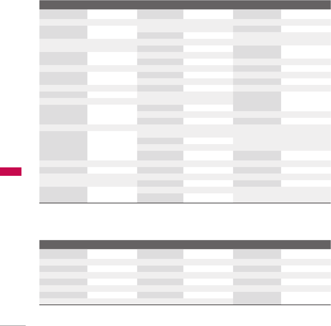
122
APPENDIX
APPENDIX
Brand Codes Brand Codes Brand Codes
ALPHASTAR DSR 123 HITACHI 139 140 RCA 066 106
AMPLICA 050 HOUSTON
TRACKER
033 037 039 051
057 104
REALISTIC 043 074
ASTRO PHILIPS(ML) 159 SAMSUNG 123
HUGHES 068 SATELLITE SERVICE
CO
028 035 047 057
085
ASTRO
THOMPSON(ML)
160 HUMAX(SL) 158
JANIEL 060 147 SCIENTIFIC
ATLANTA
032 138
ASTRO NOKIA(ML) 161 JERROLD 061
KATHREIN 108 SKY LIFE 150
BIRDVIEW 051 126 129 LEGEND 057 SONY 103
CHANNEL MASTER 013 014 015 018
036 055
LG 001 STARCAST 041
LUTRON 132 SUPER GUIDE 020 124 125
CHAPARRAL 008 009 012 077 LUXOR 062 144 SAMART(TH) 156
CITOH 054 MACOM 010 059 063 064
065
TEECOM 023 026 075 087
088 090 107 130
137
CURTIS MATHES 050 145
DRAKE 005 006 007 010
011 052 112 116
141
MEMOREX 057
NEXTWAVE 028 124 125 TOSHIBA 002 127
NORSAT 069 070 TRUE VISION(TH) 155
DX ANTENNA 024 046 056 076 PACE SKY SATEL-
LITE
143 UNIDEN 016 025 042 043
044 045 048 049
078 079 080 086
101 135 136
ECHOSTAR 038 040 057 058
093 094 095 096
097 098 099 100
122
PANASONIC 060 142
PANSAT 121
PERSONAL CABLE 117 UBC(TH) 153
ELECTRO HOME 089 PHILIPS 071 UBC/SAMART(TH) 154
EUROPLUS 114 PICO 105 VIEWSTAR 115
FUJITSU 017 021 022 027
133 134
PRESIDENT 019 102 VTC(VN) 162
PRIMESTAR 030 110 111 WINEGARD 128 146
GENERAL
INSTRUMENT
003 004 016 029
031 059 101
PROSAT 072 ZENITH 081 082 083 084
091 120
PSI(TH) 157
HDSTB
DVD
Brand Codes Brand Codes Brand Codes
APEX DIGITAL 022 MITSUBISHI 002 RCA 005 006
DENON 020 014 NAD 023 SAMSUNG 011 015
GE 005 006 ONKYO 008 017 SONY 007
HARMAN KARDON 027 PANASONIC 003 009 THOMPSON 005 006
JVC 012 PHILIPS 013 TOSHIBA 019 008
LG 001 010 016 025 PIONEER 004 026 YAMAHA 009 018
MAGNAVOX 013 PROCEED 021 ZENITH 010 016 025
MARANTZ 024 PROSCAN 005 006
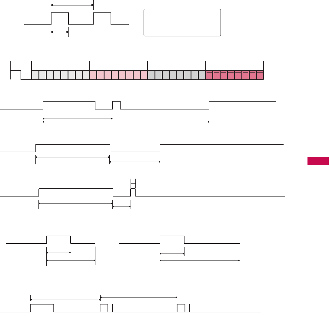
123
APPENDIX
2.25 ms
9 ms
0.55 ms
4.5 ms
9 ms
T1
Tc
Low
custom code
Lead
code
High
custom code Data code Data code
C0 C1 C2 C3 C4 C5 C6 C7 D0 D1 D2 D3 D4 D5 D6 D7 D0 D1 D2 D3 D4 D5 D6 D7
Lead code
Repeat code Tf
Lead code Low custom code High custom code Data code
Lead code Low custom code High custom code Data code
High custom code Data code Data code
C0 C1 C2 C3 C4 C5 C6 C7 C0 C1 C2 C3 C4 C5 C6 C7 D0 D1 D2 D3 D4 D5 D6 D7 D0 D1 D2 D3 D4 D5 D6 D7
Lead code Low custom code High custom code Data code Data code
Tf Tf
Tf=108ms @455KHz
0.56 ms 0.56 ms
1.12 ms 2.24 ms
Bit “1”Bit “0”
V
Configuration of frame
1st frame
Repeat frame
V
Lead code
V
Repeat code
V Bit description
V Frame interval: Tf
The waveform is transmitted as long as a key is depressed.
1. How to Connect
V Connect your wired remote control to the Remote Control port on the TV.
2. Remote Control IR Codes
V Output waveform
Single pulse, modulated with 37.917KHz signal at 455KHz
Carrier frequency
FCAR = 1/TC = fOSC/12
Duty ratio = T1/TC = 1/3
IR CODES
124
APPENDIX
APPENDIX
Code
(Hexa) Function Note Code
(Hexa) Function Note
08 POWER Remote control Button (Power On/Off) D6 TV Discrete IR Code
(TV Input Selection)
0F TV Remote control Button
0B INPUT Remote control Button 5A AV1 Discrete IR Code
(AV1 Input Selection)
0A SAP Remote control Button
79 7 RATIO Remote control Button D0 AV2 Discrete IR Code
(AV2 Input Selection)
AB GUIDE Remote control Button
OC PORTAL Remote control Button BF COMPONENT Discrete IR Code
(COMPONENT Input Selection)
AA INFO Remote control Button
10-19 Number Key 0-9 Remote control Button D5 RGB-PC Discrete IR Code
(RGB Input Selection)
4C - (Dash) Remote control Button
1A FLASHBK Remote control Button CE HDMI1 Discrete IR Code
(HDMI1 Input Selection)
02 VOL + Remote control Button
03 VOL - Remote control Button CC HDMI2 Discrete IR Code
(HDMI2 Input Selection)
00 CH
ὤ㨴㥄
Remote control Button
01 CH
ὤ㨴㥄
Remote control Button 76 Ratio 4:3 Discrete IR Code
(Only 4:3 Mode)
0E 8 TIMER Remote control Button
39 CC Remote control Button 77 Ratio 16:9 Discrete IR Code
(Only 16:9 Mode)
09 MUTE Remote control Button
43 MENU or Home Remote control Button AF Ratio Zoom Discrete IR Code
(Only Zoom Mode)
5B RETURN Remote control Button
40
ὤ㨴㥄
Remote control Button C4 POWER ON Discrete IR Code
(Only Power On)
41
ὤ㨴㥄
Remote control Button
07
ὤ㨴㥄
Remote control Button C5 POWER OFF Discrete IR Code
(Only Power Off)
06
ὤ㨴㥄
Remote control Button
44 ENTER Remote control Button
60 PIP Remote control Button
71 PIP CH + Remote control Button
72 PIP CH- Remote control Button
63 PIP SWAP Remote control Button
61 PIP INPUT Remote control Button
C1 A (Stop) Remote control Button
C0 G (Play) Remote control Button
C2 ; (Pause) Remote control Button
C3 O (Record) Remote control Button

125
APPENDIX
GNU GENERAL PUBLIC LICENSE
Version 2, June 1991
making the program proprietary. To prevent this, we have made
it clear that any patent must be licensed for everyone's free use
or not licensed at all.
The precise terms and conditions for copying, distribution and
modification follow.
GNU GENERAL PUBLIC LICENSE
TERMS AND CONDITIONS FOR COPYING, DISTRIBUTION
AND MODIFICATION
0. This license applies to any program or other work which
contains a notice placed by the copyright holder saying it
may be distributed under the terms of this General Public
License. The "Program", below, refers to any such program or
work, and a "work based on the Program" means either the
Program or any derivative work under copyright law: that is
to say, a work containing the Program or a portion of it,
either verbatim or with modifications and/or translated into
another language. (Hereinafter, translation is included
without limitation in the term "modification".) Each licensee
is addressed as "you".
Activities other than copying, distribution and modification
are not covered by this license; they are outside its scope.
The act of running the Program is not restricted, and the
output from the program is covered only if its contents
constitute a work based on the program (independent of
having been made by running the program). Whether that is
true depends on what the program does.
1. You may copy and distribute verbatim copies of the
program's source code as you receive it, in any medium,
provided that you conspicuously and appropriately publish
on each copy an appropriate copyright notice and disclaimer
of warranty; keep intact all the notices that refer to this
license and to the absence of any warranty; and give any
other recipients of the program a copy of this license along
with the Program.
You may charge a fee for the physical act of transferring a
copy, and you may at your option offer warranty protection
in exchange for a fee.
2. You may modify your copy or copies of the program or any
portion of it, thus forming a work based on the Program, and
copy and distribute such modifications or work under the
terms of section 1 above, provided that you also meet all of
these conditions:
Copyright (C) 1989, 1991 Free Software Foundation, Inc., 51
Franklin Street, Fifth Floor, Boston, MA 02110-1301 USA
Everyone is permitted to copy and distribute verbatim copies of
this license document, but changing it is not allowed.
Preamble
The licenses for most software are designed to take away your
freedom to share and change it. By contrast, the GNU General
Public License is intended to guarantee your freedom to share
and change free software - to make sure the software is free for
all its users. This General Public License applies to most of the
Free Software Foundation's software and to any other program
whose authors commit to using it. (Some other free software
foundation software is covered by the GNU Lesser General
Public License instead.) You can apply it to your programs, too.
When we speak of free software, we are referring to freedom, not
price. Our General Public Licenses are designed to make sure
that you have the freedom to distribute copies of free software
(and charge for this service if you wish), that you receive source
code or can get it if you want it, that you can change the
software or use pieces of it in new free programs; and that you
know you can do these things.
To protect your rights, we need to make restrictions that forbid
anyone to deny you these rights or to ask you to surrender the
rights. These restrictions translate to certain responsibilities for
you if you distribute copies of the software, or if you modify it.
For example, if you distribute copies of such a program, whether
gratis or for a fee, you must give the recipients all the rights that
you have. You must make sure that they, too, receive or can get
the source code. And you must show them these terms so they
know their rights.
We protect your rights with two steps: (1) copyright the
software, and (2) offer you this license which gives you legal
permission to copy, distribute and/or modify the software.
Also, for each author's protection and ours, we want to make
certain that everyone understands that there is no warranty for
this free software. If the software is modified by someone else
and passed on, we want its recipients to know that what they
have is not the original, so that any problems introduced by
others will not reflect on the original authors' reputations.
Finally, any free program is threatened constantly by software
patents. We wish to avoid the danger that redistributors of a
free program will individually obtain patent licenses, in effect
OPEN SOURCE LICENSE

126
APPENDIX
APPENDIX
a) You must cause the modified files to carry prominent
notices stating that you changed the files and the date of
any change.
b) You must cause any work that you distribute or publish,
that in whole or in part contains or is derived from the
Program or any part there of, to be licensed as a whole at
no charge to all third parties under the terms of this
license.
c) If the modified program normally reads commands
interactively when run, you must cause it, when started
running for such interactive use in the most ordinary way,
to print or display an announcement including an
appropriate copyright notice and a notice that there is no
warranty (or else, saying that you provide a warranty) and
that users may redistribute the program under these
conditions, and telling the user how to view a copy of this
license. (Exception: if the Program itself is interactive but
does not normally print such an announcement, your work
based on the Program is not required to print an
announcement.)
These requirements apply to the modified work as a whole. If
identifiable sections of that work are not derived from the
Program, and can be reasonably considered independent and
separate works in themselves, then this license, and its terms,
do not apply to those sections when you distribute them as
separate works. But when you distribute the same sections as
part of a whole which is a work based on the Program, the
distribution of the whole must be on the terms of this license,
whose permissions for other licensees extend to the entire
whole, and thus to each and every part regardless of who
wrote it.
Thus, it is not the intent of this section to claim rights or
contest your rights to work written entirely by you; rather,
the intent is to exercise the right to control the distribution
of derivative or collective works based on the program.
In addition, mere aggregation of another work not based on
the program with the Program (or with a work based on the
program) on a volume of a storage or distribution medium
does not bring the other work under the scope of this license.
3. You may copy and distribute the program (or a work based
on it, under section 2) in object code or executable form
under the terms of sections 1 and 2 above provided that you
also do one of the following:
a) Accompany it with the complete corresponding
machine-readable source code, which must be distributed
under the terms of sections 1 and 2 above on a medium
customarily used for software interchange; or,
b) Accompany it with a written offer, valid for at least three
years, to give any third party, for a charge no more than
your cost of physically performing source distribution, a
complete machine-readable copy of the corresponding
source code, to be distributed under the terms of sections
1 and 2 above on a medium customarily used for software
interchange; or,
c) Accompany it with the information you received as to the
offer to distribute corresponding source code. (This
alternative is allowed only for noncommercial distribution
and only if you received the program in object code or
executable form with such an offer, in accord with
Subsection b above.)
The source code for a work means the preferred form of the
work for making modifications to it. For an executable work,
complete source code means all the source code for all
modules it contains, plus any associated interface definition
files, plus the scripts used to control compilation and
installation of the executable. However, as a special
exception, the source code distributed need not include
anything that is normally distributed (in either source or
binary form) with the major components (compiler, kernel,
and so on) of the operating system on which the executable
runs, unless that component itself accompanies the
executable.
If distribution of executable or object code is made by
offering access to copy from a designated place, then
offering equivalent access to copy the source code from the
same place counts as distribution of the source code, even
though third parties are not compelled to copy the source
along with the object code.
4. You may not copy, modify, sublicense, or distribute the
Program except as expressly provided under this license. Any
attempt otherwise to copy, modify, sublicense or distribute
the Program is void, and will automatically terminate your
rights under this license. However, parties who have received
copies, or rights, from you under this license will not have
their licenses terminated so long as such parties remain in full
compliance.
5. You are not required to accept this license, since you have
not signed it. However, nothing else grants you permission to
modify or distribute the Program or its derivative works.
These actions are prohibited by law if you do not accept this
license. Therefore, by modifying or distributing the program
(or any work based on the program), you indicate your
acceptance of this license to do so, and all its terms and
conditions for copying, distributing or modifying the program
or works based on it.
6. Each time you redistribute the program (or any work based

127
APPENDIX
on the Program), the recipient automatically receives a
license from the original licensor to copy, distribute or
modify the Program subject to these terms and conditions.
You may not impose any further restrictions on the
recipients' exercise of the rights granted herein. You are not
responsible for enforcing compliance by third parties to this
license.
7. If, as a consequence of a court judgment or allegation of
patent infringement or for any other reason (not limited to
patent issues), conditions are imposed on you (whether by
court order, agreement or otherwise) that contradict the
conditions of this license, they do not excuse you from the
conditions of this license. If you cannot distribute so as to
satisfy simultaneously your obligations under this license and
any other pertinent obligations, then as a consequence you
may not distribute the program at all. For example, if a patent
license would not permit royalty-free redistribution of the
program by all those who receive copies directly or indirectly
through you, then the only way you could satisfy both it and
this license would be to refrain entirely from distribution of
the program.
If any portion of this section is held invalid or unenforceable
under any particular circumstance, the balance of the section
is intended to apply and the section as a whole is intended to
apply in other circumstances.
It is not the purpose of this section to induce you to infringe
any patents or other property right claims or to contest
validity of any such claims; this section has the sole purpose
of protecting the integrity of the free software distribution
system, which is implemented by public license practices.
Many people have made generous contributions to the wide
range of software distributed through that system in reliance
on consistent application of that system; it is up to the
author/donor to decide if he or she is willing to distribute
software through any other system and a licensee cannot
impose that choice.
This section is intended to make thoroughly clear what is
believed to be a consequence of the rest of this license.
8. If the distribution and/or use of the program is restricted in
certain countries either by patents or by copyrighted
interfaces, the original copyright holder who places the
program under this license may add an explicit geographical
distribution limitation excluding those countries, so that
distribution is permitted only in or among countries not thus
excluded. In such case, this license incorporates the limitation
as if written in the body of this license.
9. The Free Software Foundation may publish revised and/or
new versions of the General Public License from time to time.
Such new versions will be similar in spirit to the present
version, but may differ in detail to address new problems or
concerns.
Each version is given a distinguishing version number. If the
program specifies a version number of this license which
applies to it and "any later version", you have the option of
following the terms and conditions either of that version or of
any later version published by the Free Software Foundation.
If the program does not specify a version num-
ber of this license, you may choose any version ever pub-
lished by the Free Software Foundation.
10. If you wish to incorporate parts of the program into other
free programs whose distribution conditions are different,
write to the author to ask for permission. For software which
is copyrighted by the Free Software Foundation, write to the
Free Software Foundation; we sometimes make exceptions for
this. Our decision will be guided by the two goals of
preserving the free status of all derivatives of our free
software and of promoting the sharing and reuse of software
generally.
NO WARRANTY
11. BECAUSE THE PROGRAM IS LICENSED FREE OF CHARGE,
THERE IS NO WARRANTY FOR THE PROGRAM, TO THE
EXTENT PERMITTED BY APPLICABLE LAW. EXCEPT WHEN
OTHERWISE STATED IN WRITING THE COPYRIGHT
HOLDERS AND/OR OTHER PARTIES PROVIDE THE
PROGRAM "AS IS" WITHOUT WARRANTY OF ANY KIND,
EITHER EXPRESSED OR IMPLIED, INCLUDING, BUT NOT
LIMITED TO, THE IMPLIED WARRANTIES OF
MERCHANTABILITY AND FITNESS FOR A PARTICULAR
PURPOSE. THE ENTIRE RISK AS TO THE QUALITY AND
PERFORMANCE OF THE PROGRAM IS WITH YOU. SHOULD
THE PROGRAM PROVE DEFECTIVE, YOU ASSUME THE
COST OF ALL NECESSARY SERVICING, REPAIR OR
CORRECTION.
12. IN NO EVENT UNLESS REQUIRED BY APPLICABLE LAW OR
AGREED TO IN WRITING WILL ANY COPYRIGHT HOLDER,
OR ANY OTHER PARTY WHO MAY MODIFY AND/OR
REDISTRIBUTE THE PROGRAM AS PERMITTED ABOVE, BE
LIABLE TO YOU FOR DAMAGES, INCLUDING ANY GENERAL,
SPECIAL, INCIDENTAL OR CONSEQUENTIAL DAMAGES
ARISING OUT OF THE USE OR INABILITY TO USE THE
PROGRAM (INCLUDING BUT NOT LIMITED TO LOSS OF
DATA OR DATA BEING RENDERED INACCURATE OR
LOSSES SUSTAINED BY YOU OR THIRD PARTIES OR A
FAILURE OF THE PROGRAM TO OPERATE WITH ANY
OTHER PROGRAMS), EVEN IF SUCH HOLDER OR OTHER
PARTY HAS BEEN ADVISED OF THE POSSIBILITY OF SUCH
DAMAGES.

128
APPENDIX
APPENDIX
END OF TERMS AND CONDITIONS
How to apply these terms to your new programs
If you develop a new program, and you want it to be of the
greatest possible use to the public, the best way to achieve this
is to make it free software which everyone can re distrib ute
and change under these terms.
To do so, attach the following notices to the program. It is safest
to attach them to the start of each source file to most
effectively convey the exclusion of warranty; and each file should
have at least the "copyright" line and a pointer to where the full
notice is found.
one line to give the program's name and a brief idea of what it
does.
Copyright (C) <year> <name of author>
This program is free software; you can redistribute it and/or
modify it under the terms of the GNU General Public License as
published by the Free Software Foundation; either version 2 of
the license, or (at your option) any later version.
This program is distributed in the hope that it will be useful, but
WITHOUT ANY WARRANTY; without even the implied warranty
of MERCHANTABILITY or FITNESS FOR A PARTICULAR
PURPOSE. See the GNU General Public License for more details.
You should have received a copy of the GNU General Public
License along with this program; if not, write to the Free
Software Foundation, Inc., 51 Franklin Street, Fifth Floor,
Boston, MA 02110-1301 USA.
Also add information on how to contact you by electronic and
paper mail.
If the program is interactive, make it output a short notice like
this when it starts in an interactive mode:
Gnomovision version 69, Copyright (C) year name of author
Gnomovision comes with ABSOLUTELY NO WARRANTY; for
details type ‘show w’. This is free software, and you are welcome
to redistribute it under certain conditions; type ‘show c’ for
details.
The hypothetical commands ‘show w’ and ‘show c’ should show
the appropriate parts of the General Public License. Of course,
the commands you use may be called something other than
‘show w’ and ‘show c’; they could even be mouse-clicks or menu
items-whatever suits your program.
You should also get your employer (if you work as a
programmer) or your school, if any, to sign a “copyright
disclaimer” for the program, if necessary. Here is a sample; alter
the names:
Yoyodyne, Inc., hereby disclaims all copyright interest in the
program ‘Gnomovision’ (which makes passes at compilers)
written by James Hacker.
signature of Ty Coon, 1 April 1989
Ty Coon, President of Vice
This General Public License does not permit incorporating your
program into proprietary programs. If your program is a
subroutine library, you may consider it more useful to permit
linking proprietary applications with the library. If this is what
you want to do, use the GNU Lesser General Public License
instead of this license.

129
APPENDIX
GNU LESSER GENERAL PUBLIC LICENSE
Version 2.1, February 1999
To protect each distributor, we want to make it very clear that
there is no warranty for the free library. Also, if the library is
modified by someone else and passed on, the recipients should
know that what they have is not the original version, so that the
original author's reputation will not be affected by problems that
might be introduced by others.
Finally, software patents pose a constant threat to the existence
of any free program. We wish to make sure that a company
cannot effectively restrict the users of a free program by
obtaining a restrictive license from a patent holder. Therefore,
we insist that any patent license obtained for a version of the
library must be consistent with the full freedom of use specified
in this license.
Most GNU software, including some libraries, is covered by the
ordinary GNU General Public License. This license, the GNU
Lesser General Public License, applies to certain designated
libraries, and is quite different from the ordinary General Public
License. We use this license for certain libraries in order to
permit linking those libraries into non-free programs.
When a program is linked with a library, whether statically or
using a shared library, the combination of the two is legally
speaking a combined work, a derivative of the original library.
The ordinary General Public License therefore permits such
linking only if the entire combination fits its criteria of freedom.
The Lesser General Public License permits more lax criteria for
linking other code with the library.
We call this license the "Lesser" General Public License because
it does Less to protect the user's freedom than the ordinary
General Public License. It also provides other free software
developers Less of an advantage over competing non-free
programs. These disadvantages are the reason we use the
ordinary General Public License for many libraries. However, the
Lesser license provides advantages in certain special
circumstances.
For example, on rare occasions, there may be a special need to
encourage the widest possible use of a certain library, so that it
becomes a de-facto standard. To achieve this, non-free
programs must be allowed to use the library. A more frequent
case is that a free library does the same job as widely used
non-free libraries. In this case, there is little to gain by limiting
the free library to free software only, so we use the Lesser
General Public License.
In other cases, permission to use a particular library in non-free
programs enables a greater number of people to use a large
body of free software. For example, permission to use the GNU
C Library in non-free programs enables many more people to use
Copyright (C) 1991, 1999 Free Software Foundation, Inc. 51
Franklin Street, Fifth Floor, Boston, MA 02110-1301 USA
Everyone is permitted to copy and distribute verbatim copies of
this license document, but changing it is not allowed.
[This is the first released version of the Lesser GPL. It also counts
as the successor of the GNU Library Public License, version 2,
hence the version number 2.1.]
Preamble
The licenses for most software are designed to take away your
freedom to share and change it. By contrast, the GNU General
Public Licenses are intended to guarantee your freedom to share
and change free software - to make sure the software is free for
all its users.
This license, the Lesser General Public License, applies to some
specially designated software packages - typically libraries - of
the Free Software Foundation and other authors who decide to
use it. You can use it too, but we suggest you first think
carefully about whether this license or the ordinary General
Public License is the better strategy to use in any particular case,
based on the explanations below.
When we speak of free software, we are referring to freedom of
use, not price. Our General Public Licenses are designed to make
sure that you have the freedom to distribute copies of free
software (and charge for this service if you wish); that you
receive source code or can get it if you want it; that you can
change the software and use pieces of it in new free programs;
and that you are informed that you can do these things.
To protect your rights, we need to make restrictions that forbid
distributors to deny you these rights or to ask you to surrender
these rights. These restrictions translate to certain
responsibilities for you if you distribute copies of the library or
if you modify it.
For example, if you distribute copies of the library, whether
gratis or for a fee, you must give the recipients all the rights that
we gave you. You must make sure that they, too, receive or can
get the source code. If you link other code with the library, you
must provide complete object files to the recipients, so that they
can relink them with the library after making changes to the
library and recompiling it. And you must show them these terms
so they know their rights.
We protect your rights with a two-step method: (1) we
copyright the library, and (2) we offer you this license, which
gives you legal permission to copy, distribute and/or modify the
library.

130
APPENDIX
APPENDIX
Whether that is true depends on what the library does and
what the program that uses the library does.
1. You may copy and distribute verbatim copies of the library's
complete source code as you receive it, in any medium,
provided that you conspicuously and appropriately publish
on each copy an appropriate copyright notice and disclaimer
of warranty; keep intact all the notices that refer to this
license and to the absence of any warranty; and distribute a
copy of this license along with the Library.
You may charge a fee for the physical act of transferring a
copy, and you may at your option offer warranty protection
in exchange for a fee.
2. You may modify your copy or copies of the Library or any
portion of it, thus forming a work based on the Library, and
copy and distribute such modifications or work under the
terms of section 1 above, provided that you also meet all of
these conditions:
a) The modified work must itself be a software library.
b) You must cause the files modified to carry prominent
notices stating that you changed the files and the date of
any change.
c) You must cause the whole of the work to be licensed at no
charge to all third parties under the terms of this license.
d) If a facility in the modified Library refers to a function or a
table of data to be supplied by an application program
that uses the facility, other than as an argument passed
when the facility is invoked, then you must make a good
faith effort to ensure that, in the event an application does
not supply such function or table, the facility still o p e r -
ates, and performs whatever part of its purpose remains
meaningful.
(For example, a function in a library to compute square roots
has a purpose that is entirely well-defined independent of the
application. Therefore, Subsection 2d requires that any
application-supplied function or table used by this function
must be optional: if the application does not supply it, the
square root function must still compute square roots.)
These requirements apply to the modified work as a whole. If
identifiable sections of that work are not derived from the
library, and can be reasonably considered independent and
separate works in themselves, then this license, and its terms,
do not apply to those sections when you distribute them as
separate works. But when you distribute the same sections as
part of a whole which is a work based on the library, the
distribution of the whole must be on the terms of this license,
whose permissions for other licenses extend to the entire
whole, and thus to each and every part regardless of who
wrote it.
Thus, it is not the intent of this section to claim rights or
contest your rights to work written entirely by you; rather,
the whole GNU operating system, as well as its variant, the
GNU/Linux operating system.
Although the Lesser General Public License is Less protective of
the users' freedom, it does ensure that the user of a program
that is linked with the Library has the freedom and the
wherewithal to run that program using a modified version of the
Library.
The precise terms and conditions for copying, distribution and
modification follow. Pay close attention to the difference
between a "work based on the library" and a "work that uses the
library". The former contains code derived from the library,
whereas the latter must be combined with the library in order to
run.
GNU LESSER GENERAL PUBLIC LICENSE
TERMS AND CONDITIONS FOR COPYING, DISTRIBUTION
AND MODIFICATION
0. This license agreement applies to any software library or
other program which contains a notice placed by the
copyright holder or other authorized party saying it may be
distributed under the terms of this Lesser General Public
License (also called “this license”). Each license is addressed
as "you".
A “library” means a collection of software functions and/or
data prepared so as to be conveniently linked with
application programs (which use some of those functions and
data) to form executables.
The “Library”, below, refers to any such software library or
work which has been distributed under these terms. A “work
based on the Library” means either the Library or any
derivative work under copyright law: that is to say, a work
containing the library or a portion of it, either verbatim or
with modifications and/or translated straightforwardly into
another language. (Hereinafter, translation is included
without limitation in the term “modification”.)
“Source code” for a work means the preferred form of the
work for making modifications to it. For a library, complete
source code means all the source code for all modules it con-
tains, plus any associated interface definition files, plus the
scripts used to control compilation and installation of the
library.
Activities other than copying, distribution and modification
are not covered by this license; they are outside its scope.
The act of running a program using the Library is not
restricted, and output from such a program is covered only if
its contents constitute a work based on the library
(independent of the use of the Library in a tool for writing it).

131
APPENDIX
threshold for this to be true is not precisely defined by law.
If such an object file uses only numerical parameters, data
structure layouts and accessories, and small macros and small
inline functions (ten lines or less in length), then the use of
the object file is unrestricted, regardless of whether it is
legally a derivative work. (Executable containing this object
code plus portions of the library will still fall under Section 6.)
Otherwise, if the work is a derivative of the library, you may
distribute the object code for the work under the terms of
Section 6. Any executable containing that work also fall under
Section 6, whether or not they are linked directly with the
library itself.
6. As an exception to the sections above, you may also combine
or link a "work that uses the library" with the library to
produce a work containing portions of the library, and
distribute that work under terms of your choice, provided
that the terms permit modification of the work for the
customer's own use and reverse engineering for debugging
such modifications.
You must give prominent notice with each copy of the work
that the library is used in it and that the Library and its use
are covered by this license. You must supply a copy of this
license. If the work during execution displays copyright
notices, you must include the copyright notice for the library
among them, as well as a reference directing the user to the
copy of this license. Also, you must do one of these things:
a) Accompany the work with the complete corresponding
machine-readable source code for the library including
whatever changes were used in the work (which must be
distributed under Sections 1 and 2 above); and, if the
work is an executable linked with the Library, with the
complete machine-readable “work that uses the Library”,
as object code and/or source code, so that the user can
modify the library and then relink to produce a modified
executable containing the modified library. (It is
understood that the user who changes the contents of
definitions files in the library will not necessarily be able to
recompile the application to use the modified definitions.)
b) Use a suitable shared library mechanism for linking with
the library. A suitable mechanism is one that (1) uses at
run time a copy of the library already present on the user’s
computer system, rather than copying library functions
into the executable, and (2) will operate properly with a
modified version of the library, if the user installs one, as
long as the modified version is interface-compatible with
the version that the work was made with.
c) Accompany the work with a written offer, valid for at least
three years, to give the same user the materials specified
in Subsection 6, above, for a charge no more than the cost
of performing this distribution.
d) If distribution of the work is made by offering access to
copy from a designated place, offer equivalent access to
copy the above specified materials from the same place.
the intent is to exercise the right to control the distribution
of derivative or collective works based on the library.
In addition, mere aggregation of another work not based on
the library with the library (or with a work based on the
library) on a volume of a storage or distribution medium does
not bring the other work under the scope of this license.
3. You may opt to apply the terms of the ordinary GNU General
Public License instead of this License to a given copy of the
Library. To do this, you must alter all the notices that refer to
this License, so that they refer to the ordinary GNU General
Public License, version 2, instead of to this License. (If a
newer version than version 2 of the ordinary GNU General
Public License has appeared, then you can specify that
version instead if you wish.) Do not make any other change
in these notices.
Once this change is made in a given copy, it is irreversible for
that copy, so the ordinary GNU General Public License
applies to all subsequent copies and derivative works made
from that copy.
This option is useful when you wish to copy part of the code
of the library into a program that is not a library.
4. You may copy and distribute the library (or a portion or
derivative of it, under Section 2) in object code or executable
form under the terms of Sections 1 and 2 above provided
that you accompany it with the complete corresponding
machine-readable source code, which must be distributed
under the terms of sections 1 and 2 above on a medium
customarily used for software interchange.
If distribution of object code is made by offering access to
copy from a designated place, then offering equivalent access
to copy the source code from the same place satisfies the
requirement to distribute the source code, even though third
parties are not compelled to copy the source along with the
object code.
5. A program that contains no derivative of any portion of the
Library, but is designed to work with the Library by being
compiled or linked with it, is called a “work that uses the
Library”. Such a work, in isolation, is not a derivative work of
the Library, and therefore falls outside the scope of this
license.
However, linking a “work that uses the library” with the
Library creates an executable that is a derivative of the
Library (because it contains portions of the library), rather
than a “work that uses the library”. The executable is
therefore covered by this license. Section 6 states terms for
distribution of such executable.
When a “work that uses the library” uses material from a
header file that is part of the library, the object code for the
work may be a derivative work of the library even though the
source code is not.
Whether this is true is especially significant if the work can be
linked without the library, or if the work is itself a library. The

132
APPENDIX
APPENDIX
the Library), the recipient automatically receives a license
from the original licensor to copy, distribute, link with or
modify the library subject to these terms and conditions. You
may not impose any further restrictions on the recipients'
exercise of the rights granted herein.
You are not responsible for enforcing compliance by third
parties with this license.
11. If, as a consequence of a court judgment or allegation of
patent infringement or for any other reason (not limited to
patent issues), conditions are imposed on you (whether by
court order, agreement or otherwise) that contradict the
conditions of this license, they do not excuse you from the
conditions of this license. If you cannot distribute so as to
satisfy simultaneously your obligations under this license and
any other pertinent obligations, then as a consequence you
may not distribute the library at all. For example, if a patent
license would not permit royalty-free redistribution of the
library by all those who receive copies directly or indirectly
through you, then the only way you could satisfy both it and
this license would be to refrain entirely from distribution of
the library.
If any portion of this section is held invalid or unenforceable
under any particular circumstance, the balance of the section
is intended to apply, and the section as a whole is intended
to apply in other circumstances.
It is not the purpose of this section to induce you to infringe
any patents or other property right claims or to contest
validity of any such claims; this section has the sole purpose
of protecting the integrity of the free software distribution
system which is implemented by public license practices.
Many people have made generous contributions to the wide
range of software distributed through that system in reli-
ance on consistent application of that system; it is up to the
author/donor to decide if he or she is willing to dis-
tribute software through any other system and a license can-
not impose that choice.
This section is intended to make thoroughly clear what is
believed to be a consequence of the rest of this license.
12. If the distribution and/or use of the library is restricted in
certain countries either by patents or by copyrighted
interfaces, the original copyright holder who places the
library under this license may add an explicit geographical
distribution limitation excluding those countries, so that
distribution is permitted only in or among countries not thus
excluded. In such case, this license incorporates the limitation
as if written in the body of this license.
13. The Free Software Foundation may publish revised and/or
new versions of the Lesser General Public License from time
to time. Such new versions will be similar in spirit to the pres-
ent version, but may differ in detail to address new problems
or concerns.
Each version is given a distinguishing version number. If the
e) Verify that the user has already received a copy of these
materials or that you have already sent this user a copy.
For an executable, the required form of the "work that uses
the library" must include any data and utility programs
needed for reproducing the executable from it. However, as a
special exception, the materials to be distributed need not
include anything that is normally distributed (in either source
or binary form) with the major components (compiler, kernel,
and so on) of the operating system on which the executable
runs, unless that component itself accompanies the
executable.
It may happen that this requirement contradicts the license
restrictions of other proprietary libraries that do not
normally accompany the operating system. Such a
contradiction means you cannot use both them and the
library together in an executable that you distribute.
7. You may place library facilities that are a work based on the
library side-by-side in a single library together with other
library facilities not covered by this license, and distribute
such a combined library, provided that the separate
distribution of the work based on the Library and of the other
library facilities is otherwise permitted, and provided that you
do these two things:
a) Accompany the combined library with a copy of the same
work based on the Library, uncombined with any other
library facilities. This must be distributed under the terms
of the sections above.
b) Give prominent notice with the combined library of the
fact that part of it is a work based on the library, and
explaining where to find the accompanying uncombined
form of the same work.
8. You may not copy, modify, sublicense, link with, or distribute
the library except as expressly provided under this license.
Any attempt otherwise to copy, modify, sublicense, link with,
or distribute the library is void, and will automatically
terminate your rights under this license. However, parties
who have received copies, or rights, from you under this
license will not have their licenses terminated so long as such
parties remain in full compliance.
9. You are not required to accept this license, since you have
not signed it. However, nothing else grants you permission to
modify or distribute the library or its derivative works. These
actions are prohibited by law if you do not accept this
license. Therefore, by modifying or distributing the library (or
any work based on the library), you indicate your acceptance
of this license to do so, and all its terms and conditions for
copying, distributing or modifying the library or works based
on it.
10. Each time you redistribute the library (or any work based on

133
APPENDIX
END OF TERMS AND CONDITIONS
How to apply these terms to your new libraries
If you develop a new library, and you want it to be of the
greatest possible use to the public, we recommend making it
free software that everyone can redistribute and change. You
can do so by permitting redistribution under these terms (or,
alternatively, under the terms of the ordinary General Public
License).
To apply these terms, attach the following notices to the
library. It is safest to attach them to the start of each source
file to most effectively convey the exclusion of warranty; and
each file should have at least the “copyright” line and a pointer
to where the full notice is found.
one line to give the library's name and a brief idea of what it
does.
Copyright (C) <year> <name of author>
This library is free software; you can redistribute it and/or
modify it under the terms of the GNU Lesser General Public
License as published by the Free Software Foundation; either
version 2.1 of the license, or (at your option) any later version.
This library is distributed in the hope that it will be useful, but
WITHOUT ANY WARRANTY; without even the implied
warranty of MERCHANTABILITY or FITNESS FOR A
PARTICULAR PURPOSE. See the GNU Lesser General Public
License for more details.
You should have received a copy of the GNU Lesser General
Public License along with this library; if not, write to the Free
Software Foundation, Inc., 51 Franklin Street, Fifth Floor,
Boston, MA 02110-1301 USA
Also add information on how to contact you by electronic and
paper mail.
You should also get your employer (if you work as a
programmer) or your school, if any, to sign a “copyright
disclaimer” for the library, if necessary. Here is a sample; alter
the names:
Yoyodyne, Inc., hereby disclaims all copyright interest in the
library ‘Frob’ (a library for tweaking knobs) written by James
Random Hacker.
signature of Ty Coon, 1 April 1990
Ty Coon, President of Vice
library specifies a version number of this license which
applies to it and “any later version”, you have the option of
following the terms and conditions either of that version or
of any later version published by the Free Software
Foundation.
If the library does not specify a license version number, you
may choose any version ever published by the Free
Software Foundation.
14. If you wish to incorporate parts of the library into other
free programs whose distribution conditions are
incompatible with these, write to the author to ask for
permission. For software which is copyrighted by the Free
Software Foundation, write to the Free Software Foundation;
we sometimes make exceptions for this. Our decision will be
guided by the two goals of preserving the free status of all
derivatives of our free software and of promoting the
sharing and reuse of software generally.
NO WARRANTY
15. BECAUSE THE LIBRARY IS LICENSED FREE OF CHARGE,
THERE IS NO WARRANTY FOR THE LIBRARY, TO THE
EXTENT PERMITTED BY APPLICABLE LAW. EXCEPT WHEN
OTHERWISE STATED IN WRITING THE COPYRIGHT
HOLDERS AND/OR OTHER PARTIES PROVIDE THE
LIBRARY "AS IS" WITHOUT WARRANTY OF ANY KIND,
EITHER EXPRESSED OR IMPLIED, INCLUDING, BUT NOT
LIMITED TO, THE IMPLIED WARRANTIES OF
MERCHANTABILITY AND FITNESS FOR A PARTICULAR
PURPOSE. THE ENTIRE RISK AS TO THE QUALITY AND
PERFORMANCE OF THE LIBRARY IS WITH YOU. SHOULD
THE LIBRARY PROVE DEFECTIVE, YOU ASSUME THE
COST OF ALL NECESSARY SERVICING, REPAIR OR
CORRECTION.
16. IN NO EVENT UNLESS REQUIRED BY APPLICABLE LAW
OR AGREED TO IN WRITING WILL ANY COPYRIGHT
HOLDER, OR ANY OTHER PARTY WHO MAY MODIFY
AND/OR REDISTRIBUTE THE LIBRARY AS PERMITTED
ABOVE, BE LIABLE TO YOU FOR DAMAGES, INCLUDING
ANY GENERAL, SPECIAL, INCIDENTAL OR
CONSEQUENTIAL DAMAGES ARISING OUT OF THE USE
OR INABILITY TO USE THE LIBRARY (INCLUDING BUT
NOT LIMITED TO LOSS OF DATA OR DATA BEING
RENDERED INACCURATE OR LOSSES SUSTAINED BY
YOU OR THIRD PARTIES OR A FAILURE OF THE LIBRARY
TO OPERATE WITH ANY OTHER SOFTWARE), EVEN IF
SUCH HOLDER OR OTHER PARTY HAS BEEN ADVISED OF
THE POSSIBILITY OF SUCH DAMAGES.

134
APPENDIX
APPENDIX
MOZILLA PUBLIC LICENSE
Version 1.1
---------------
1.10. “Original code” means source code of computer
software code which is described in the source code
notice required by exhibit as original code, and which,
at the time of its release under this license is not already
covered code governed by this license.
1.10.1. “Patent claims” means any patent claim(s), now
owned or hereafter acquired, including without
limitation, method, process, and apparatus claims, in
any patent licensable by grantor.
1.11. “Source code” means the preferred form of the covered
code for making modifications to it, including all
modules it contains, plus any associated interface
definition files, scripts used to control compilation and
installation of an executable, or source code differential
comparisons against either the original code or another
well known, available covered code of the contributor's
choice. The source code can be in a compressed or
archival form, provided the appropriate decompression
or de-archiving software is widely available for no
charge.
1.12. “You” (or “Your”) means an individual or a legal entity
exercising rights under, and complying with all of the
terms of, this license or a future version of this license
issued under section 6.1.
For legal entities, “You” includes any entity which
controls, is controlled by, or is under common control
with You. For purposes of this definition, “control”
means (a) the power, direct or indirect, to cause the
direction or management of such entity, whether by
contract or otherwise, or (b) ownership of more than
fifty percent (50%) of the outstanding shares or
beneficial ownership of such entity.
2. Source Code License.
2.1. The initial developer grant.
The initial developer hereby grants You a world-wide,
royalty-free, non-exclusive license, subject to third
party intellectual property claims:
(a) under intellectual property rights (other than pat-
ent or trademark) licensable by initial developer to
use, reproduce, modify, display, perform, sublicense
and distribute the original code (or portions there-
of) with or without modifications, and/or as part of
a larger work; and
(b) under patents claims infringed by the making, using
or selling of original code, to make, have made, use,
1.Definitions.
1.0.1. “Commercial use” means distribution or otherwise
making the covered code available to a third party.
1.1. “Contributor” means each entity that creates or
contributes to the creation of modifications.
1.2. “Contributor version” means the combination of the
original code, prior modifications used by a contributor,
and the modifications made by that particular
contributor.
1.3. “Covered code” means the original code or
modifications or the combination of the original code
and modifications, in each case including portions
thereof.
1.4. “Electronic distribution mechanism” means a mechanism
generally accepted in the software development
community for the electronic transfer of data.
1.5. “Executable” means covered code in any form other
than source code.
1.6. “Initial developer” means the individual or entity
identified as the initial Developer in the Source Code
notice required by exhibit A.
1.7. “Larger work” means a work which combines covered
code or portions thereof with code not governed by the
terms of this License.
1.8. “License” means this document.
1.8.1. “Licensable” means having the right to grant, to the
maximum extent possible, whether at the time of the
initial grant or subsequently acquired, any and all of the
rights conveyed herein.
1.9. “Modifications” means any addition to or deletion from
the substance or structure of either the original code or
any previous modifications. When covered code is
released as a series of files, a modification is:
A. Any addition to or deletion from the contents of a file
containing original code or previous modifications.
B. Any new file that contains any part of the original
code or previous modifications.

135
APPENDIX
3. Distribution Obligations.
3.1. Application of license.
The modifications which You create or to which you
contribute are governed by the terms of this license,
including without limitation section 2.2. The source
code version of covered code may be distributed only
under the terms of this license or a future version of this
license released under section 6.1, and you must
include a copy of this license with every copy of the
source code you distribute. You may not offer or
impose any terms on any source code version that
alters or restricts the applicable version of this license
or the recipients' rights hereunder. However, you may
include an additional document offering the additional
rights described in section 3.5.
3.2. Availability of source code.
Any modification which you create or to which you
contribute must be made available in source code form
under the terms of this license either on the same media
as an executable version or via an accepted electronic
distribution mechanism to anyone to whom you made
an executable version available; and if made available via
electronic distribution mechanism, must remain
available for at least twelve (12) months after the date
it initially became available, or at least six (6) months
after a subsequent version of that particular
modification has been made available to such recipients.
You are responsible for ensuring that the source code
version remains available even if the electronic
distribution mechanism is maintained by a third party.
3.3. Description of modifications.
You must cause all covered code to which you
contribute to contain a file documenting the changes
You made to create that covered code and the date of
any change. You must include a prominent statement
that the modification is derived, directly or indirectly,
from original code provided by the initial developer and
including the name of the initial developer in (a) the
source code, and (b) in any notice in an executable
version or related documentation in which you describe
the origin or ownership of the covered code.
3.4. Intellectual property matters
(a) Third party claims.
If contributor has knowledge that a license under a third
party's intellectual property rights is required to
exercise the rights granted by such contributor under
sections 2.1 or 2.2, contributor must include a text file
with the source code distribution titled "LEGAL" which
describes the claim and the party making the claim in
sufficient detail that a recipient will know whom to
practice, sell, and offer for sale, and/or otherwise
dispose of the original code (or portions there of).
(c) the licenses granted in this section 2.1(a) and (b)
are effective on the date Initial developer first
distributes original code under the terms of this
license.
(d) Notwithstanding section 2.1(b) above, no patent
license is granted: 1) for code that You delete from
the original Code; 2) separate from the original
code; or 3) for infringements caused by: i) the
modification of the original code or ii) the
combination of the original code with other
software or devices.
2.2. Contributor Grant.
Subject to third party intellectual property claims, each
contributor hereby grants You a world-wide,
royalty-free, non-exclusive license
(a) under intellectual property rights (other than
patent or trademark) licensable by contributor, to
use, reproduce, modify, display, perform, sublicense
and distribute the modifications created by such
contributor (or portions thereof) either on an
unmodified basis, with other modifications, as
covered code and/or as part of a larger work; and
(b) under patent claims infringed by the making, using,
or selling of modifications made by that contributor
either alone and/or in combination with its
contributor version (or portions of such
combination), to make, use, sell, offer for sale, have
made, and/or otherwise dispose of: 1)
modifications made by that contributor (or
portions thereof); and 2) the combination of
modifications made by that contributor with its
contributor version (or portions of such
combination).
(c) the licenses granted in sections 2.2(a) and 2.2(b)
are effective on the date contributor first makes
commercial use of the covered code.
(d) Notwithstanding section 2.2(b) above, no patent
license is granted: 1) for any code that contributor
has deleted from the contributor version; 2)
separate from the contributor version; 3) for
infringements caused by: i) third party
modifications of contributor version or ii) the
combination of modifications made by that
contributor with other software (except as part of
the contributor version) or other devices; or 4)
under patent claims infringed by covered code in
the absence of modifications made by that
contributor.

136
APPENDIX
APPENDIX
in which you describe recipients' rights relating to the
covered code. You may distribute the executable
version of covered code or ownership rights under a
license of your choice, which may contain terms
different from this license, provided that you are in
compliance with the terms of this license and that the
license for the executable version does not attempt to
limit or alter the recipient's rights in the source code
version from the rights set forth in this license. If you
distribute the executable version under a different
license you must make it absolutely clear that any terms
which differ from this license are offered by you alone,
not by the Initial developer or any contributor. You
hereby agree to indemnify the initial developer and
every contributor for any liability incurred by the initial
developer or such contributor as a result of any such
terms You offer.
3.7. Larger works.
You may create a larger work by combining covered
code with other code not governed by the terms of this
license and distribute the larger work as a single
product. In such a case, you must make sure the
requirements of this license are fulfilled for the covered
code.
4. Inability to comply due to statute or regulation.
If it is impossible for you to comply with any of the
terms of this license with respect to some or all of the
covered code due to statute, judicial order, or
regulation then you must: (a) comply with the terms of
this license to the maximum extent possible; and (b)
describe the limitations and the code they affect. Such
description must be included in the LEGAL file described
in section 3.4 and must be included with all
distributions of the source code. Except to the extent
prohibited by statute or regulation, such description
must be sufficiently detailed for a recipient of ordinary
skill to be able to understand it.
5. Application of this license.
This license applies to code to which the initial
developer has attached the notice in exhibit A and to
related covered code.
6. Versions of the license.
6.1. New versions.
Netscape communications corporation (“Netscape”)
may publish revised and/or new versions of the license
from time to time. Each version will be given a
distinguishing version number.
6.2. Effect of new versions.
Once covered code has been published under a
contact. If contributor obtains such knowledge after the
modification is made available as described in section
3.2, contributor shall promptly modify the LEGAL file in
all copies contributor makes available thereafter and
shall take other steps (such as notifying appropriate
mailing lists or newsgroups) reasonably calculated to
inform those who received the covered code that new
knowledge has been obtained.
(b) Contributor APIs.
If contributor's modifications include an application
programming interface and contributor has knowledge
of patent licenses which are reasonably necessary to
implement that API, contributor must also include this
information in the LEGAL file.
(c) Representations.
contributor represents that, except as disclosed
pursuant to section 3.4(a) above, contributor believes
that contributor's modifications are contributor's
original creation(s) and/or contributor has sufficient
rights to grant the rights conveyed by this license.
3.5. Required notices.
You must duplicate the notice in exhibit A in each file of
the source code. If it is not possible to put such notice
in a particular source code file due to its structure, then
You must include such notice in a location (such as a
relevant directory) where a user would be likely to look
for such a notice. If You created one or more
modification(s), you may add your name as a
contributor to the notice described in exhibit A. you
must also duplicate this license in any documentation
for the source code where You describe recipients'
rights or ownership rights relating to covered code. You
may choose to offer, and to charge a fee for, warranty,
support, indemnity or liability obligations to one or
more recipients of covered code. However, you may do
so only on your own behalf, and not on behalf of the
Initial developer or any contributor. You must make it
absolutely clear than any such warranty, support,
indemnity or liability obligation is offered by you alone,
and You hereby agree to indemnify the Initial developer
and every contributor for any liability incurred by the
Initial developer or such contributor as a result of
warranty, support, indemnity or liability terms you offer.
3.6. Distribution of executable versions.
You may distribute covered code in executable form
only if the requirements of section 3.1-3.5 have been
met for that covered code, and if you include a notice
stating that the source code version of the covered
code is available under the terms of this license,
including a description of how and where you have
fulfilled the obligations of section 3.2. The notice must
be conspicuously included in any notice in an
executable version, related documentation or collateral

137
APPENDIX
infringement claim (excluding declatory judgment
actions) against initial developer or a contributor (the
initial developer or contributor against whom you file
such action is referred to as “Participant”) alleging that:
(a) such participant's contributor version directly or
indirectly infringes any patent, then any and all
rights granted by such participant to you under
sections 2.1 and/or 2.2 of this license shall, upon
60 days notice from Participant terminate
prospectively, unless if within 60 days after receipt
of notice you either: (i) agree in writing to pay
participant a mutually agreeable reasonable royalty
for your past and future use of modifications made
by such participant, or (ii) withdraw your litigation
claim with respect to the contributor version against
such participant. If within 60 days of notice, a
reasonable royalty and payment arrangement are
not mutually agreed upon in writing by the parties
or the litigation claim is not withdrawn, the rights
granted by participant to you under sections 2.1
and/or 2.2 automatically terminate at the
expiration of the 60 day notice period specified
above.
(b) any software, hardware, or device, other than such
participant's contributor Version, directly or
indirectly infringes any patent, then any rights
granted to You by such participant under sections
2.1(b) and 2.2(b) are revoked effective as of the
date you first made, used, sold, distributed, or had
made, modifications made by that participant.
8.3. If you assert a patent infringement claim against
participant alleging that such participant's contributor
version directly or indirectly infringes any patent where
such claim is resolved (such as by license or settlement)
prior to the initiation of patent infringement litigation,
then the reasonable value of the licenses granted by
such participant under sections 2.1 or 2.2 shall be
taken into account in determining the amount or value
of any payment or license.
8.4. In the event of termination under sections 8.1 or 8.2
above, all end user license agreements (excluding
distributors and resellers) which have been validly
granted by you or any distributor hereunder prior to
termination shall survive termination.
9. LIMITATION OF LIABILITY.
UNDER NO CIRCUMSTANCES AND UNDER NO LEGAL
THEORY, WHETHER TORT (INCLUDING
NEGLIGENCE), CONTRACT, OR OTHERWISE, SHALL
YOU, THE INITIAL DEVELOPER, ANY OTHER
CONTRIBUTOR, OR ANY DISTRIBUTOR OF COVERED
particular version of the license, you may always
continue to use it under the terms of that version. You
may also choose to use such covered code under the
terms of any subsequent version of the license
published by netscape. No one other than netscape has
the right to modify the terms applicable to covered
code created under this license.
6.3. Derivative works.
If You create or use a modified version of this license
(which you may only do in order to apply it to code
which is not already covered code governed by this
license), You must (a) rename Your license so that the
phrases "Mozilla", "MOZILLAPL", "MOZPL", "Netscape",
"MPL", "NPL" or any confusingly similar phrase do not
appear in your license (except to note that your license
differs from this license) and (b) otherwise make it clear
that Your version of the license contains terms which
differ from the Mozilla Public license and netscape
Public License. (Filling in the name of the initial
developer, original code or contributor in the notice
described in exhibit A shall not of themselves be
deemed to be modifications of this license.)
7. DISCLAIMER OF WARRANTY.
COVERED CODE IS PROVIDED UNDER THIS LICENSE
ON AN “AS IS” BASIS, WITHOUT WARRANTY OF ANY
KIND, EITHER EXPRESSED OR IMPLIED, INCLUDING,
WITHOUT LIMITATION, WARRANTIES THAT THE
COVERED CODE IS FREE OF DEFECTS,
MERCHANTABLE, FIT FOR A PARTICULAR PURPOSE
OR NON-INFRINGING. THE ENTIRE RISK AS TO THE
QUALITY AND PERFORMANCE OF THE COVERED
CODE IS WITH YOU. SHOULD ANY COVERED CODE
PROVE DEFECTIVE IN ANY RESPECT, YOU (NOT THE
INITIAL DEVELOPER OR ANY OTHER CONTRIBUTOR)
ASSUME THE COST OF ANY NECESSARY SERVICING,
REPAIR OR CORRECTION. THIS DISCLAIMER OF
WARRANTY CONSTITUTES AN ESSENTIAL PART OF
THIS LICENSE. NO USE OF ANY COVERED CODE IS
AUTHORIZED HEREUNDER EXCEPT UNDER THIS
DISCLAIMER.
8. TERMINATION.
8.1. This license and the rights granted hereunder will
terminate automatically if you fail to comply with terms
herein and fail to cure such breach within 30 days of
becoming aware of the breach. All sublicenses to the
covered code which are properly granted shall survive
any termination of this license. Provisions which, by
their nature, must remain in effect beyond the
termination of this license shall survive.
8.2. If you initiate litigation by asserting a patent

138
APPENDIX
APPENDIX
12. RESPONSIBILITY FOR CLAIMS.
As between initial developer and the contributors, each
party is responsible for claims and damages arising,
directly or indirectly, out of its utilization of rights
under this license and you agree to work with initial
developer and contributors to distribute such
responsibility on an equitable basis. Nothing herein is
intended or shall be deemed to constitute any
admission of liability.
13. MULTIPLE-LICENSED CODE.
Initial developer may designate portions of the covered
code as "Multiple-Licensed". "Multiple-Licensed" means
that the initial developer permits you to utilize portions
of the covered code under your choice of the NPL or
the alternative licenses, if any, specified by the initial
developer in the file described in exhibit A.
EXHIBIT A -Mozilla Public License.
The contents of this file are subject to the Mozilla Public
License Version 1.1 (the “license”); you may not use this file
except in compliance with the License. You may obtain a copy
of the license at http://www.mozilla.org/MPL/
Software distributed under the license is distributed on an "AS
IS" basis, WITHOUT WARRANTY OF ANY KIND, either express
or implied. See the license for the specific language governing
rights and limitations under the License.
The Original Code is _____________________________________.
The Initial Developer of the Original Code is________________.
Portions created by _____________________ are Copyright (C)
_______________________. All Rights Reserved.
Contributor(s): __________________________________________.
Alternatively, the contents of this file may be used under the
terms of the _____ license (the "[___] License"), in which case
the provisions of [______] license are applicable instead of
those above. If you wish to allow use of your version of this file
only under the terms of the [____] license and not to allow
others to use your version of this file under the MPL, indicate
your decision by deleting the provisions above and replace
them with the notice and other provisions required by the
[___] license. If you do not delete the provisions above, a
recipient may use your version of this file under either the MPL
or the [___] license."
NOTE: The text of this exhibit A may differ slightly from the
text of the notices in the source code files of the original code.
You should use the text of this exhibit A rather than the text
found in the original code/source code for Your modifications.
CODE,OR ANY SUPPLIER OF ANY OF SUCH PARTIES,
BE LIABLE TO ANY PERSON FOR ANY INDIRECT,
SPECIAL, INCIDENTAL, OR CONSEQUENTIAL
DAMAGES OF ANY CHARACTER INCLUDING,
WITHOUT LIMITATION, DAMAGES FOR LOSS OF
GOODWILL, WORK STOPPAGE, COMPUTER FAILURE
OR MALFUNCTION, OR ANY AND ALL OTHER
COMMERCIAL DAMAGES OR LOSSES, EVEN IF SUCH
PARTY SHALL HAVE BEEN INFORMED OF THE
POSSIBILITY OF SUCH DAMAGES. THIS LIMITATION
OF LIABILITY SHALL NOT APPLY TO LIABILITY FOR
DEATH OR PERSONAL INJURY RESULTING FROM
SUCH PARTY'S NEGLIGENCE TO THE EXTENT
APPLICABLE LAW PROHIBITS SUCH LIMITATION.
SOME JURISDICTIONS DO NOT ALLOW THE
EXCLUSION OR LIMITATION OF INCIDENTAL OR
CONSEQUENTIAL DAMAGES, SO THIS EXCLUSION
AND LIMITATION MAY NOT APPLY TO YOU.
10. U.S. GOVERNMENT END USERS.
The covered code is a "commercial item," as that term
is defined in 48 C.F.R. 2.101 (Oct. 1995), consisting
of "commercial computer software" and "commercial
computer software documentation," as such terms are
used in 48 C.F.R. 12.212 (Sept. 1995). Consistent
with 48 C.F.R. 12.212 and 48 C.F.R. 227.7202-1
through 227.7202-4 (June 1995), all U.S. Government
end users acquire covered code with only those rights
set forth herein.
11. MISCELLANEOUS.
This license represents the complete agreement
concerning subject matter hereof. If any provision of
this license is held to be unenforceable, such provision
shall be reformed only to the extent necessary to make
it enforceable. This License shall be governed by
California law provisions (except to the extent
applicable law, if any, provides otherwise), excluding its
conflict-of-law provisions. With respect to disputes in
which at least one party is a citizen of, or an entity
chartered or registered to do business in the united
states of america, any litigation relating to this License
shall be subject to the jurisdiction of the federal courts
of the northern district of california, with venue lying in
santa clara county, california, with the losing party
responsible for costs, including without limitation, court
costs and reasonable attorneys' fees and expenses. The
application of the united nations convention on
contracts for the International sale of goods is
expressly excluded. Any law or regulation which
provides that the language of a contract shall be
construed against the drafter shall not apply to this
license.

LED LCD TV / LCD TV
OWNER’S MANUAL
Please read this manual carefully before operating
your set and retain it for future reference.
P/NO : SAC34134301 (1111-REV05) www.lg.com
The model and serial number of the TV is located
on the back and/or on one side of the TV.
Record these numbers below should you ever
need service.
MODEL
SERIAL
32LG710H
37LG710H
42LG710H
32LD650H
37LD650H
42LD650H
47LD650H
55LD650H
32LD655H
37LD655H
42LD655H
32LD660H
37LD660H
42LD660H
32LD665H
37LD665H
42LD665H
32LV555H
37LV555H
42LV555H
47LV555H
55LV555H
LCD TV MODELS LED LCD TV MODELS
1-800-243-0000
1-888-865-3026
1-888-542-2623
USA, Consumer User
USA, Commercial User
CANADA
LG Customer Information Center

Master TV Setup
pages 11 – 14
Cloning Information
pages 24 – 32
FTG Mode of Operation
pages 33 – 44
EXPERIENCED INSTALLER
Commercial Mode Setup Guide
Note: Selected features shown in this guide may not be available on all models.
Lodging Guest Interactive Pro:Centric™ TVs
32LD660H 37LD660H 42LD660H
32LD665H 37LD665H 42LD665H
32LV555H 37LV555H
42LV555H
47LV555H 55LV555H
© Copyright 2011, LG Electronics U.S.A., Inc. P/N: 206-4200 (Rev B)
2206-4200
MODEL and SERIAL NUMBER
The model and serial numbers of this TV are located on the
back of the cabinet. For future reference, LG suggests that
you record those numbers here:
Model No._________________ Serial No._______________
WARNING:
TO REDUCE THE RISK OF ELECTRIC SHOCK DO NOT REMOVE COVER (OR BACK). NO USER-
SERVICEABLE PARTS INSIDE. REFER TO QUALIFIED SERVICE PERSONNEL.
The lightning flash with arrowhead symbol, within an equilateral triangle, is intended to alert the user to
the presence of uninsulated “dangerous voltage” within the product’s enclosure that may be of sufficient
magnitude to constitute a risk of electric shock to persons.
The exclamation point within an equilateral triangle is intended to alert the user to the presence of important
operating and maintenance (servicing) instructions in the literature accompanying the appliance.
WARNING:
TO PREVENT FIRE OR SHOCK HAZARDS, DO NOT EXPOSE THIS PRODUCT TO RAIN OR MOISTURE.
Power Cord Polarization:
This product is equipped with a 3-wire grounding-type alternating current power plug. This plug will fit into the
power outlet only one way. This is a safety feature. If you are unable to insert the plug fully into the outlet, contact
your electrician to replace your obsolete outlet. Do not defeat the safety purpose of the 3-wire grounding-type plug.
NOTE TO CABLE/TV INSTALLER:
This reminder is provided to call the cable TV system installer’s attention to Article 820-40 of the National Electrical
Code (U.S.A.). The code provides guidelines for proper grounding and, in particular, specifies that the cable ground
shall be connected to the grounding system of the building, as close to the point of the cable entry as practical.
REGULATORY INFORMATION:
This equipment has been tested and found to comply with the limits for a Class B digital device, pursuant to Part 15 of
the FCC Rules. These limits are designed to provide reasonable protection against harmful interference when the
equipment is operated in a residential installation. This equipment generates, uses and can radiate radio frequency
energy and, if not installed and used in accordance with the instruction manual, may cause harmful interference to radio
communications. However, there is no guarantee that interference will not occur in a particular installation. If this equip-
ment does cause harmful interference to radio or television reception, which can be determined by turning the equip-
ment off and on, the user is encouraged to try to correct the interference by one or more of the following measures:
• Reorient or relocate the receiving antenna.
• Increase the separation between the equipment and receiver.
• Connect the equipment to an outlet on a circuit different from that to which the receiver is connected.
• Consult the dealer or an experienced radio/TV technician for help.
CAUTION:
Do not attempt to modify this product in any way without written authorization from LG Electronics U.S.A., Inc.
Unauthorized modification could void the user’s authority to operate this product.
COMPLIANCE:
The responsible party for this product’s compliance is: LG Electronics U.S.A., Inc.
1000 Sylvan Avenue, Englewood Cliffs, NJ 07632, USA • Phone: 1-201-816-2000
WARNING
RISK OF ELECTRIC SHOCK
DO NOT OPEN
© Copyright 2011, LG Electronics U.S.A., Inc.
For Customer Support/Service, please call:
1-888-865-3026
The latest product information and documentation is
available online at:
www.LGsolutions.com/products
Marketed and Distributed in the United States by LG Electronics U.S.A., Inc.
1000 Sylvan Avenue, Englewood Cliffs, NJ 07632
3
206-4200
IMPORTANT SAFETY INSTRUCTIONS
1. Read these instructions.
2. Keep these instructions.
3. Heed all warnings.
4. Follow all instructions.
5. Do not use this apparatus near water.
6. Clean only with dry cloth.
7. Do not block any ventilation openings. Install in accor-
dance with the manufacturer’s instructions.
8. Do not install near any heat sources, such as radiators,
heat registers, stoves, or other apparatus (including
amplifiers) that produce heat.
9. Do not defeat the safety purpose of the polarized or
grounding-type plug. A polarized plug has two blades
with one wider than the other. A grounding-type plug
has two blades and a third grounding prong. The wide
blade or the third prong are provided for your safety. If
the provided plug does not fit into your outlet, consult
an electrician for replacement of the obsolete outlet.
10. Protect the power cord from being walked on or pinched,
particularly at plugs, convenience receptacles, and the
point where it exits from the apparatus.
11. Only use attachments/accessories specified by the
manufacturer.
12. Use only with the cart, stand, tripod, bracket, or table
specified by the manufacturer or sold with the appara-
tus. When a cart is used, use caution when moving the
cart/apparatus combination in order to avoid injury from
tip-over.
13.
Refer all servicing to qualied service personnel.
Servicing is required when the apparatus has been dam-
aged in any way, such as power-supply cord or plug is
damaged, liquid has been spilled or objects have fallen
into the apparatus, the apparatus has been exposed to
rain or moisture, does not operate normally, or has been
dropped.
14. Never touch this apparatus or antenna during a thunder or
lighting storm.
15. When mounting a TV on the wall, make sure not to install
the TV by the hanging power and signal cables on the back
of the TV.
16. Do not allow an impact shock or any objects to fall into the
product, and do not drop objects onto the screen.
17. Power Cord
Caution: It is recommended that appliances be placed
upon a dedicated circuit; that is, a single outlet circuit
which powers only that appliance and has no additional
outlets or branch circuits. Check the specification page
in the Owner’s Manual to be certain.
Periodically examine the cord of your appliance, and if its
appearance indicates damage or deterioration, unplug it,
discontinue use of the appliance, and have the cord replaced
with an exact replacement part by an authorized servicer.
Protect the power cord from physical or mechanical abuse,
such as twisting, kinking, or pinching or being closed in a
door or walked upon. Pay particular attention to plugs, wall
outlets, and the point where the cord exits the appliance.
Do not use a damaged or loose power cord. Be sure to grasp
the plug when unplugging the power cord. Do not pull on the
power cord to unplug the TV.
18. Overloading
Do not connect too many appliances to the same AC power
outlet as this could result in fire or electric shock. Do not
overload wall outlets. Overloaded wall outlets, loose or dam-
aged wall outlets, extension cords, frayed power cords, or
damaged or cracked wire insulation are dangerous. Any of
these conditions could result in re or electric shock.
19. Outdoor Use/Wet Location
Warning: To reduce the risk of re or electrical
shock, do not expose this product to rain,
moisture or other liquids.
Do not touch the TV with wet hands. Do not install this prod-
uct near ammable objects such as gasoline or candles or
expose the TV to direct air conditioning.
Do not expose to dripping or splashing and do not place
objects lled with liquids, such as vases, cups, etc., on or over
the apparatus (e.g., on shelves above the unit).
20. Grounding
Ensure that you connect the earth ground wire to prevent
possible electric shock (i.e., a TV with a three-prong ground-
ed AC plug must be connected to a three-prong grounded AC
outlet). If grounding methods are not possible, have a quali-
ed electrician install a separate circuit breaker. Do not try to
ground the unit by connecting it to telephone wires, lightening
rods, or gas pipes.
21. Disconnect Device
The mains plug is the disconnecting device. The plug must
remain readily operable.
As long as this unit is connected to the AC wall outlet, it is not
disconnected from the AC power source even if you turn off
this unit by SWITCH.
(Continued on next page)
PORTABLE CART WARNING
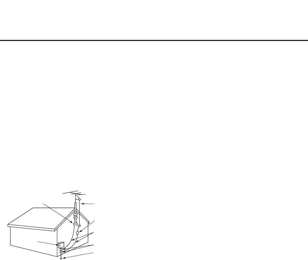
4206-4200
IMPORTANT SAFETY INSTRUCTIONS
(Continued from previous page)
22. Outdoor Antenna Grounding
If an outside antenna or cable system is connected to the
product, follow the precautions below.
An outdoor antenna system should not be located in the
vicinity of overhead power lines or other electric light or
power circuits or where it can come into contact with such
power lines or circuits as death or serious injury can occur.
Be sure the antenna system is grounded so as to provide
some protection against voltage surges and built-up static
charges.
Article 810 of the National Electrical Code (NEC) in the U.S.A.
provides information with respect to proper grounding of the
mast and supporting structure, grounding of the lead-in wire
to an antenna-discharge unit, size of grounding conductors,
location of antenna-discharge unit, connection to grounding
electrodes, and requirements for the grounding electrode.
Antenna Grounding According to NEC, ANSI/NFPA 70
23. Cleaning
When cleaning, unplug the power cord and wipe gently with
a soft cloth to prevent scratching. Do not spray water or
other liquids directly on the TV as electric shock may occur.
Do not clean with chemicals such as alcohol, thinners or
benzene.
24. Transporting Product
Make sure the TV is turned Off and unplugged and that all
cables have been removed. It may take two or more people
to carry larger TVs. Do not press against or put stress on the
front panel of the TV during transport.
25. Ventilation
Install the TV where there is proper ventilation. Do not install
in a conned space such as a bookcase. Do not cover the
product with cloth or other materials (e.g., plastic) while it is
plugged in. Do not install in excessively dusty places.
26. Do not touch the ventilation openings, as they may become
hot while the TV is operating.
27. If you smell smoke or other odors coming from the TV or
hear strange sounds, unplug the power cord, and contact an
authorized service center.
28. Do not press against the front panel of the TV with your
hand or a sharp object (e.g., a nail, pencil, or pen) or make a
scratch on it.
29. Keep the product away from direct sunlight.
30. Dot Defect
The LCD panel is a high technology product with resolution
of two million to six million pixels. In a very few cases, you
could see ne dots on the screen while you are viewing the
TV. Those dots are deactivated pixels and do not affect the
performance and reliability of the TV.
31. Generated Sound
“Cracking”: A cracking noise that occurs while the TV is
On or when it is turned Off is generated by plastic thermal
contraction due to temperature and humidity. This noise is
common for products where thermal deformation is required.
Electrical circuit humming/panel buzzing: A low level noise
is generated from a high-speed switching circuit, which sup-
plies a large amount of current to operate a product. It varies
depending on the product. This generated sound does not
affect the performance and reliability of the product.
32. For LCD TV
If the TV feels cold to the touch, there may be a small “icker”
when it is turned On. This is normal; there is nothing wrong
with the TV. Some minute dot defects may be visible on the
screen, appearing as tiny red, green, or blue spots. However,
they have no adverse effect on the TV’s performance. Avoid
touching the LCD screen or holding your nger(s) against it for
long periods of time. Doing so may produce some temporary
distortion effects on the screen.
Antenna Lead in Wire
Antenna Discharge Unit
(NEC Section 810-20)
Grounding Conductor
(NEC Section 810-21)
Ground Clamps
Power Service Grounding
Electrode System (NEC
Art 250, Part H)
Ground Clamp
Electric Service
Equipment

5
206-4200
Table of Contents
Safety Warnings.................................. 2
Important Safety Instructions . . . . . . . . . . . . . . . . . . . . . . 3
–
4
Table of Contents................................. 5
Commercial Mode Overview . . . . . . . . . . . . . . . . . . . . . . 6
–
7
Setup Checklist................................. 6
Pass-through Mode.............................. 6
FTG Mode..................................... 7
Remote Management in FTG Mode . . . . . . . . . . . . . . . . . 7
External MPI Control............................. 7
Pro:Centric Operation............................8
–
9
Pro:Centric TV Interactive Menu Features . . . . . . . . . . . . 8
Pro:Centric Setup ............................... 9
Pro:Centric Modes of Operation . . . . . . . . . . . . . . . . . . . . 9
Installer Remote Control Typical Key Functions . . . . . . . . 10
Master TV Setup ............................. 11
–
14
Before You Begin ...............................11
Cloning Methods................................11
Clonable TV Setup Menu Features . . . . . . . . . . . . . . . . .11
Master TV Setup Procedure . . . . . . . . . . . . . . . . . . . . . . 12
Installer Menu ...............................15
–
22
Accessing the Installer Menu . . . . . . . . . . . . . . . . . . . . . 15
Using the Installer Menu . . . . . . . . . . . . . . . . . . . . . . . . . 15
Exiting the Installer Menu and Activating Updates . . . . . 15
Channel Icons / Custom Text Labels
(2-5-4 + MENU Mode)............................. 23
Cloning Overview ............................... 24
USB Cloning Procedures......................25
–
28
Learning / Teaching a Master TV Setup using
a USB Memory Device / .tlx File. . . . . . . . . . . . . . . . . . . 25
Learning / Teaching a Master TV Setup using
a USB Memory Device / .tll File . . . . . . . . . . . . . . . . . . . .
27
Clone Programmer Cloning Procedures ........ 29
–
32
Learning / Teaching a Master TV Setup using
a TLL-1100A Clone Programmer . . . . . . . . . . . . . . . . . . 29
Learning / Teaching a Master TV Setup using
an LT2002 Clone Programmer . . . . . . . . . . . . . . . . . . . . 31
FTG Mode of Operation Overview ..............33
–
34
FTG Mode via CPU or EBL . . . . . . . . . . . . . . . . . . . . . . 33
Determining the TV Operating Mode . . . . . . . . . . . . . . . 34
FTG Mode via CPU ...........................35
–
38
Creating an FTG Configuration File using the
FTG File Manager.............................. 35
Teaching FTG Configuration to a TV . . . . . . . . . . . . . . . 37
Learning an FTG Configuration File from a TV . . . . . . . 38
Optional Manual Configuration / TV Setup . . . . . . . . . . . 39
FTG Mode via EBL (Local Configuration) ........... 40
FTG File Manager Utilities Overview . . . . . . . . . . . . . . 41
–
44
FTG File Manager Main Screen . . . . . . . . . . . . . . . . . . . 41
FTG Channel Map Configuration Utility . . . . . . . . . . . . . 42
FTG Channel Map Editor . . . . . . . . . . . . . . . . . . . . . . . . 43
FTG Installer Menu Configuration Utility. . . . . . . . . . . . . 44
IP Environment Setup ........................45
–
46
Remote Jack Pack / TV Connections & Setup . . . . . . . . . 47
References
Upgrading TV/PTC Software using a USB Memory
Device......................................... 48
Downloading a Splash Screen using a USB Memory
Device......................................... 49
Power Consumption Settings . . . . . . . . . . . . . . . . . . . . 50
–
51
TV Camport Auto Sense Operation . . . . . . . . . . . . . . . . . . 52
TV Aux Input Configuration . . . . . . . . . . . . . . . . . . . . . . . . 53
b-LAN Setup & Overview.......................... 54
RJP Model List and Input Auto-sensing Hierarchy. . . . . . . 55
Resetting Factory Defaults on the TV(s) . . . . . . . . . . . . . . 56
TV Zone Restrictions ............................. 57
LD660H/LD665H Rear Jack Panel . . . . . . . . . . . . . . . . . . 58
LV555H Rear Jack Panel . . . . . . . . . . . . . . . . . . . . . . . . . . 59
Side Connections Panel . . . . . . . . . . . . . . . . . . . . . . . . . . . 60
RF Antenna Connection........................... 61
Troubleshooting ..............................62
– 65
General Troubleshooting. . . . . . . . . . . . . . . . . . . . . . . . . 62
Troubleshooting Flow Chart . . . . . . . . . . . . . . . . . . . . . . 63
Commercial Mode Check / FTG Operation
Troubleshooting ............................... 64
Clone Programmer Troubleshooting . . . . . . . . . . . . . . . . 65
Glossary of Terms ............................... 66
Document Revision History / Notes . . . . . . . . . . . . . . . . . . 67
Back Cover..................................... 68
Notes
• Installer Menu content is intended for use primarily by qualied TV electronics technicians.
• Refer to the Owner’s Manual for additional information on TV installation, features, specications, maintenance, and safety
instructions.
• Design and specications subject to change without prior notice.

6206-4200
Commercial Mode Overview
Typical Installer Menu
xxLD66xH PTC INSTALLER MENU
000 INSTALLER SEQ 000
UPN 000-000-000-000 ASIC D279
PTC V1.00.016 CPU V1.21.00
Installer Menu
To set up a Master TV for cloning purposes, you will
need to know how to enter the commercial controller
(PTC) Installer Menu and make changes to the
default values as required. If necessary, familiarize
yourself with the Installer Menu and how to make
and save changes. Refer to pages 15 to 22 for
information on accessing the Installer Menu in Pass-
through Mode and for detailed descriptions of the
Installer Menu items.
TV Setup Menus
On-screen setup menus control the features of the
TV. Use the Installer Remote to access the TV setup
menus, and set the TV features to the desired
configuration for the end user. Refer to the Owner’s
Manual for detailed information on the TV setup
menus.
This document describes how to set up LD660H/LD665H and LV555H Pro:Centric™ TVs for Commercial
Mode operation. LG commercial TV functionality is based on “ownership” of the Channel Map; that is,
the Channel Map resides in the TV’s CPU, Protocol Translator Card (PTC), or embedded b-LAN™ (EBL)
module, or it resides externally from the TV (i.e., in a device from the solution provider).
Each of these TV models has an EBL module that can be configured either for Pass-through Mode
(default) or Free-To-Guest (FTG) Mode. In addition, each of these TVs is capable of FTG Mode operation
via the TV CPU when the EBL is in Pass-through Mode.
Setup Checklist
Note: This document provides information specific to Commercial Mode operation. Refer to the Owner’s
Manual for detailed information on TV installation and hardware and cable connections.
Installation
__ Unpack TV and all accessories.
__ Install batteries in the Installer Remote.
__ Install TV on VESA mount or stand.
Note: It may be advisable to make all cable
connections before installing on VESA mount
or stand, as appropriate.
Hardware Connections
__ Install any additional hardware as
appropriate to your institution, LAN, etc.
Cable Connections
__ Make all rear jack panel and MPI card slot
connections, as appropriate.
Commercial Mode Setup
__ Complete appropriate procedures as described
in this document for Commercial Mode operation.
See “Pass-through Mode” and “FTG Mode”
sections below for further information.
Pass-through Mode
This mode allows you to create a Master TV Setup for cloning purposes for TVs that are to remain in Pass-
through Mode. This mode also allows external control via the GAME CONTROL/MPI port on the TV rear jack
panel. Use the Installer Remote to congure Installer Menu items as required for TV operation and set up TV
features (Channel, Picture, Audio, etc.). See “Master TV Setup” on pages 11 to 14 for detailed information.
TV Setup Menus
PICTURE AUDIO
INPUT
OPTION
TIME
USB
CHANNEL
LOCK

7
206-4200
Commercial Mode Overview (Cont.)
Cloning
Cloning refers to the process of capturing a Master TV Setup and transferring it to a Target TV (both TVs
must be in Pass-through Mode). The Master TV’s clonable setup menu options should be configured as
part of the Master TV Setup. If there are features in the Master TV’s setup—channel icons or labels, digital
font options, etc.—that are not set or that are set incorrectly, those features also will not be set or will be
set incorrectly in the Target TVs. Pages 24 to 32 provide detailed information on cloning requirements and
procedures.
FTG Mode
This mode enables Pro:Idiom
® decryption and also allows logical channel mapping of physical channels
to remove the need for dash tuning. TV operation in FTG Mode is based on which element of the TV owns
the FTG Logical Channel Map—the CPU or the EBL. Understanding the application in which the TV will be
used is vital in determining the owner.
As indicated above, FTG mode operation in the LD660H/LD665H and LV555H models can be provided
either by the TV CPU or EBL. These are two separate and distinct FTG Modes of operation, each with
its own unique advantages and requirements as described later in this document. When the TV CPU is
configured with an FTG Channel Map, the CPU controls the operation of the TV, and when the EBL is
configured with an FTG Channel Map, the EBL controls the operation of the TV.
Once it is determined whether the TV CPU or the EBL will own the FTG Channel Map, conguration can
begin. Conguration of either requires a PC application—the LG FTG File Manager for the TV CPU or
the LG FTG Device Conguration Application for the EBL. Each application provides utilities that enable
you to create/edit an FTG Channel Map and congure Installer Menu settings. See pages 33 to 44 for
further information on FTG Mode operation and conguration.
Remote Management in FTG Mode
When the TV is configured for FTG Mode via CPU, remote management of the FTG Channel Map and
FTG Installer Menu settings is provided by a Pro:Centric server. Refer to the Pro:Centric™ Server
Admin Client User Guide for further information.
When the TV is configured for FTG Mode via EBL, the b-LAN module, which is internal to the TV, allows
hotel/institution head end equipment (for example, an FMA-LG101) with b-LAN technology to communi-
cate with the TV to provide remote management of the FTG Channel Map and FTG Installer Menu set-
tings. See Reference section, “b-LAN Setup & Overview,” for further information.
External MPI Control
To control the TV using an external MPI control device, you must use the TV’s GAME CONTROL/MPI port
for communication purposes. In these TVs, Installer Menu item 118 POWER SAVINGS controls the power
circuitry for both the embedded b-LAN module and the GAME CONTROL/MPI port; therefore, to ensure
that the GAME CONTROL/MPI port circuitry is powered, thus enabling MPI communication, Installer Menu
item 118 POWER SAVINGS must be set appropriately. See Installer Menu item descriptions as well as
Reference section, “b-LAN Setup & Overview,” for further information.
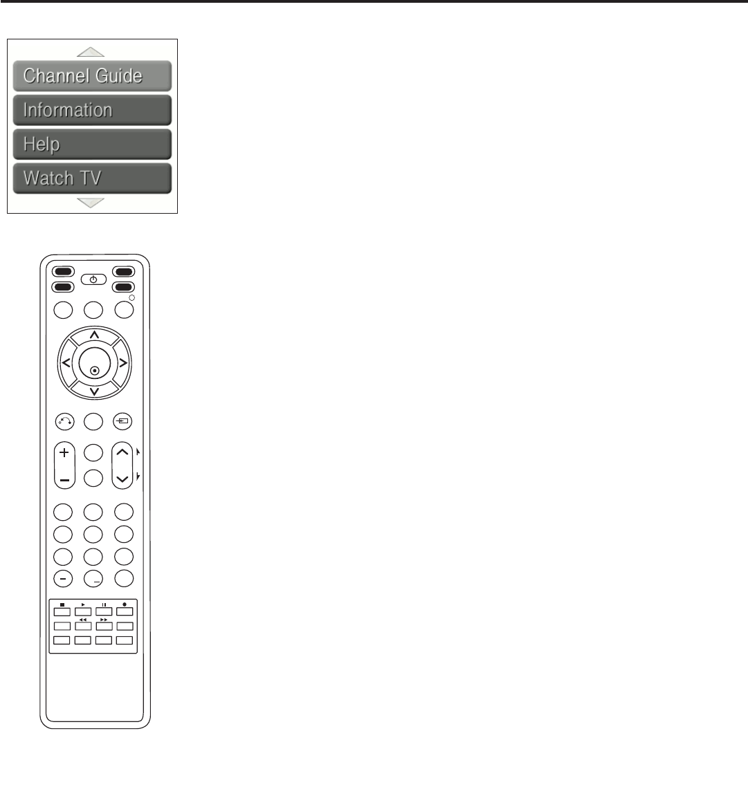
8206-4200
Pro:Centric TV Interactive Menu Features
The interactive Pro:Centric TV enables guests—from the comfort of their hotel
rooms—to view and select from a complete listing of hotel services and amenities.
The Pro:Centric TV is connected to the hotel's billing computer, and service/amenities
charges are billed at the time of order.
Interactive amenities may include:
• Hotel information, news, and events
• Directory services (tourist attractions, restaurants, etc.)
• Reservation services (business meetings, tness, spa, etc.)
• Weather and trafc information
• Shopping services (delivery to guest room)
• Room service (menu ordering, memo service, morning wake up call, laundry, etc.)
• Ticketing and gaming services
• Check-out service (in the guest room)
• E-mail resources/account access
Use the Installer Remote to operate both interactive menus and regular TV features.
Press PORTAL on the Installer Remote to access the interactive menus.
Note: Interactive menu options may vary, depending on Pro:Centric features enabled
for the site. The following are default interactive menus.
Channel Guide
Shows available TV networks and logical channels. When available, electronic
program guide (EPG) data provides additional channel and program information.
Information
Typically displays hotel information, for example, photos of guest rooms, dining
rooms, business centers, facilities, etc., as well as information on local weather and
attractions. Information may also include resources, such as local school programs,
run in cooperation with the hotel.
Help
Provides help for navigating the interactive menus.
Watch TV
Removes the interactive menu from the screen and returns to the previously tuned TV
channel.
Pro:Centric Operation
123
456
789
0
ABC DEF
GHI JKL MNO
PQRS TUV WXYZ
PIP CH- PIP CH+
PIP SWAP PIP INPUT
PIP SAP
FLASHBK
REMOVE
ALPHA/NUM
P
A
G
E
MUTE
TIMER
MENU
RETURN
VOL CH
POWER
GUIDE
INPUT
CC
ENTER
TV DVD
VCR
STB
&@
.:/,
RATIO
PORTAL INFO i

9
206-4200
Pro:Centric Operation (Cont.)
Pro:Centric Setup
The Pro:Centric server provides the following functionality:
• Remote management/administration (TV E-Z Installation): The Pro:Centric server Admin Client provides
remote management/administration facilities for downloading splash screens and software/firmware
updates as well as facilities for downloading FTG Channel Map and FTG Installer Menu settings for TVs
that are in FTG Mode via CPU (see also “Remote Management in FTG Mode” on page 7).
The Data Channel must be set appropriately to enable Pro:Centric remote management/administration
facilities. The Data Channel can be set either in the Installer Menu (item 119 DATA CHANNEL) or in the
Pro:Centric Menu (see “Pro:Centric Setup” on page 46).
• Pro:Centric application: The application comprises the Pro:Centric interactive menus/features described
on the previous page. Pro:Centric application settings are managed via the Pro:Centric server Admin
Client.
In addition to the Data Channel, the Pro:Centric Application Mode must be set appropriately to enable
the Pro:Centric application. The Pro:Centric Application Mode can be set either in the Installer Menu
(item 098 PRO:CENTRIC) or in the Pro:Centric Menu (see “Pro:Centric Setup” on page 46).
Administration and management options for the Pro:Centric server are described in detail in the
Pro:Centric™ Server Admin Client User Guide. This document describes only those settings that must
be specied on the TVs.
Pro:Centric Modes of Operation
There are now two modes that enable Pro:Centric operation, as described below.
FTG Mode via CPU
This mode enables Pro:Idiom decryption and also allows logical channel mapping of physical channels as
described in the introduction to this document. See pages 33 to 44 for further information on FTG Mode
operation and conguration.
Application Tuning Mode
If the TV is not in FTG Mode, but both the Data Channel and the Pro:Centric Application Mode have been
set in the Installer Menu or the Pro:Centric Menu, the TV enters Application Tuning Mode. In Application
Tuning Mode, the logical channel mapping of physical channels is done in the Pro:Centric application.
Also in Application Tuning Mode, only the Function Menu is available to end users instead of the TV setup
menus (see sample display of the Function Menu under “Determining the TV Operating Mode” on page
34). Additionally, all Channel Map updates must be administered from the Pro:Centric server Admin Client;
Teach To TV options will not be available from the USB Download Menu.
Note: The Installer Menu remains editable while the TV is in Application Tuning Mode.
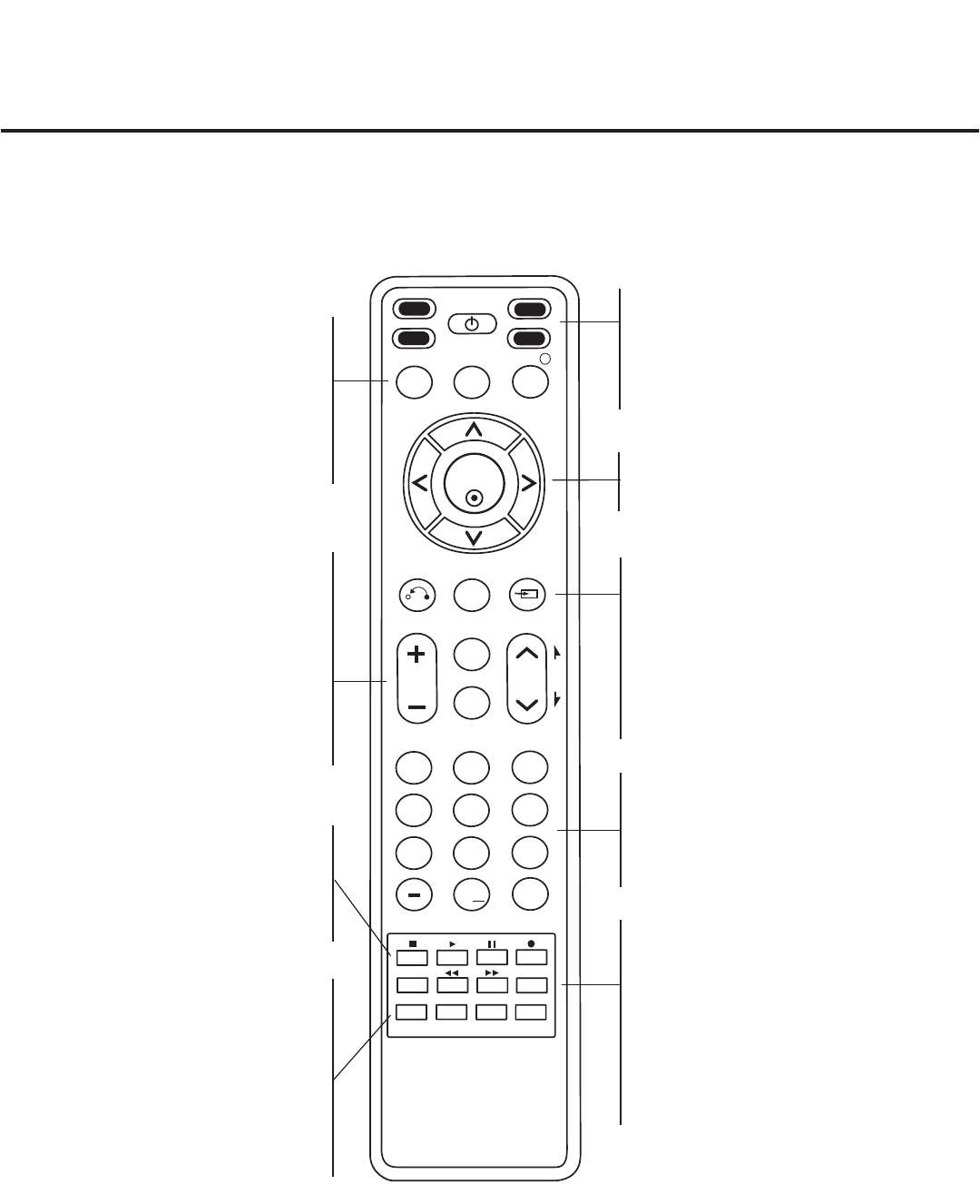
10 206-4200
Installer Remote Control Typical Key Functions
123
456
789
0
ABC DEF
GHI JKL MNO
PQRS TUV WXYZ
PIP CH- PIP CH+
PIP SWAP PIP INPUT
PIP SAP
FLASHBK
REMOVE
ALPHA/NUM
P
A
G
E
MUTE
TIMER
MENU
RETURN
VOL CH
POWER
GUIDE
INPUT
CC
ENTER
TV DVD
VCR
STB
&@
.:/,
RATIO
PORTAL INFO i
NUMBER Buttons (0 - 9) & DASH
Use to enter a program number or channel.
Dash is used for sub-channel numbers such
as 2-1, 2-2, 9-1, 9-2, 100-3, 100-4, etc.
FLASHBK (FLASHBACK)
Returns to the previously tuned channel.
RATIO
Adjusts the picture aspect ratio.
TIMER
Sets the amount of time before the TV
automatically turns itself OFF.
SAP
Analog Mode: Selects MTS sound (Mono,
Stereo, or SAP). DTV Mode: Changes the
audio language, if additional languages are
available. *
The LG Installer Remote is supplied with and dedicated to operate the TV. The LG Installer Remote illustrated
below and throughout this document shows typical remote control functions and is provided for reference only.
This Installer Remote may vary from the Installer Remote supplied with the TV.
DVD/VCR BUTTONS
Control some LG DVD/VCR products.
(RECORD button not functional in DVD
mode.)
Color buttons access special functions
in some menus.
VOLUME UP/DOWN
Increases/decreases sound level.
CC
Press to activate subtitles.
MUTE
Switches sound ON or OFF.
CHANNEL/PAGE UP/DOWN
Changes the channel. Moves from
one full set of screen information to
the next.
Arrows (Up/Down/Left/Right) & ENTER
Use to navigate on-screen menus and adjust
TV settings to your requirements.
RETURN
Returns one level to the previous menu/display.
MENU
Displays the TV setup menus on the screen.
Also exits the on-screen menu system and
returns to TV viewing.
INPUT
Selects RGB, HDMI/DVI1, HDMI2, Component
Input, AV1, and AV2 sources.
GUIDE
Displays and removes the electronic
program guide.
PORTAL
Displays and removes the interactive
menu.
INFO
Displays channel information.
PIP
Toggles through PIP options.
PIP CH +/-
Changes the PIP channel.
PIP SWAP
Exchange the main/sub images.
PIP INPUT
Select the connected input source for the
sub-picture.
TV/STB/DVD/VCR
Select the remote’s operating mode: TV, STB,
DVD, or VCR.
POWER
Turns TV or any other programmed equipment
ON or OFF, depending on mode.
SAP notes:
• If SAP is selected and no SAP is provided, sound
may not be heard on channel.
• Each analog channel may have its own SAP setting.
• Digital channels will reset to default audio language
with a power off/on.
*

11
206-4200
Master TV Setup
This section describes how to set up a Master TV for cloning purposes when the TV is in Pass-through
Mode.
Note: Refer to FTG Mode information on pages 33 to 44 for details on entering FTG Mode and
conguring/editing FTG Channel Map and FTG Installer Menu settings.
Before You Begin
• Disconnect all Aux inputs if you intend to run Auto Tuning (Channel Search). Under certain conditions,
Auto Tuning is disabled if there is an Aux input active.
• Determine which cloning tool—USB memory device or clone programmer—is appropriate for your
application; several of the Master TV Setup procedure steps are dependent on the cloning tool to be
used. See “Cloning Methods” below for further information.
• If you intend to use a USB memory device, determine the type of le—either the new “.tlx” le format or
the legacy “.tll” le format—to use for cloning purposes; several of the Master TV Setup procedure steps
are dependent on the desired le type. See “Cloning Methods” below for further information.
Cloning Methods
Using a USB Memory Device / .tlx File
• The .tlx le format clones the following menu settings: Installer Menu settings, IP Environment Offset
Setup and Pro:Centric Setup settings (see pages 45 and 46), and all TV sources’ (analog, digital, AV1,
HDMI, etc.) clonable setup menu settings. See “Clonable TV Setup Menu Features” list below.
• Not intended for cloning an auto-tuned/edited Channel Map, as the channel lineup is converted to a logical
FTG Channel Map when saved (Learned) from a TV to a .tlx le. If the .tlx le with the FTG Channel Map
is then used for Teaching purposes, all Target TVs will be congured for FTG Mode via CPU.
Using a USB Memory Device / .tll File
The .tll le format clones the contents of the commercial controller (PTC) memory, including an auto-tuned/
edited Channel Map, Installer Menu settings, and one TV source’s (analog, digital, or Aux) clonable setup
menu settings. See “Clonable TV Setup Menu Features” list below.
Using a Clone Programmer (TLL-1100A or LT2002)
Both the TLL-1100A and LT2002 clone the contents of the commercial controller (PTC) memory, including
an auto-tuned/edited Channel Map, Installer Menu settings, and one TV source’s (analog or Aux) clonable
setup menu settings. See “Clonable TV Setup Menu Features” list below.
Clonable TV Setup Menu Features
Channel
Auto Tuning (Channel Lineup)
Manual Tuning
Channel Edit
Channel Label
Picture
Aspect Ratio
Picture Mode
Audio
Auto Volume
Clear Voice
Sound Mode
Balance
TV Speaker
Time
Auto Clock
Auto Off (Sleep Timer)
Option
Menu Language
Audio Language
Caption
Lock
Movie Rating
TV Rating – Children
TV Rating – General
Note: Some menu options vary between analog and digital channels and Aux inputs.
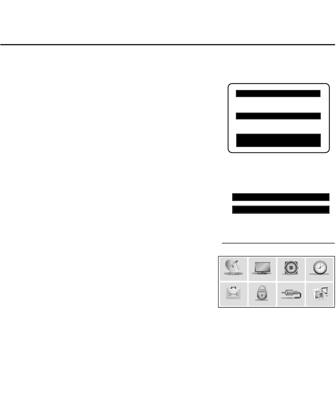
12 206-4200
Typical Installer Menu
Note: The Installer Menu header will vary
depending on the TV you are setting up.
Adjust the settings for these
Installer Menu items.
Master TV Setup Procedure
1. Set Installer Menu items.
This step provides specic instruction only on the Installer Menu
items that should be set on a Master TV. Refer to pages 15 to 22
for detailed information on all Installer Menu items.
a) Make sure the TV is ON. Then, use the Installer Remote to
enter the PTC Installer Menu: Press MENU repeatedly until
the on-screen display of the TV setup menus no longer
toggles, and then press 9-8-7-6 + ENTER.
b) Set Installer Menu item 117 FACT DEFAULT to 001 and press
ENTER on the Installer Remote.
This clears all Installer Menu custom settings, channel lineup,
etc. and reloads the factory default settings. The value will
change back to 0 after the PTC has been restored to factory
default condition. This step ensures that the TV Channel
Memory will be the active channel lineup.
c) Set Installer Menu item 003 BAND/AFC, as appropriate.
• Broadcast: Set to 000. • HRC: Set to 002.
• CATV: Set to 001 (default). • IRC: Set to 003.
d) Set any other Installer Menu items that affect your TV pro-
gramming network to the required conguration. For example,
enable/disable Aux inputs, set a Start Channel, etc.
e) After you have adjusted all required Installer Menu item
settings, press ENTER once on the Installer Remote to save
your changes; then, press ENTER again to exit the menu.
2. Set up TV features.
On-screen setup menus control the features of the TV. Press
MENU on the Installer Remote to access the TV setup menus,
and then set Channel, Picture, Audio, Lock, Time, etc. options to
the desired configurations. See also the Clonable TV Setup Menu
Features list on page 11.
Note: If you intend to clone the PTC, remember that only one TV
source’s clonable setup menu settings will be cloned. Thus, for a
clone programmer, the TV setup menu settings should be applica-
ble to either an analog channel or Aux input, while for a USB
device / .tll file, the TV setup menu settings should be applicable
to the analog or digital channel or Aux input to which the Target
TV will be set during the Teaching process.
Note: If desired and if appropriate depending on the cloning
method you intend to use (see “Cloning Methods” on previous
page), you can run Auto Tuning (see step 3) prior to completing
this step.
(Continued on next page)
xxLD66xH PTC INSTALLER MENU
000 INSTALLER SEQ 000
UPN 000-000-000-000 ASIC D279
PTC V1.00.016 CPU V1.21.00
117 FACT DEFAULT 001
003 BAND/AFC 00X
Master TV Setup (Cont.)
Use the TV setup menus to set the TV
features to the desired configuration
for the end user.
PICTURE AUDIO
INPUT
OPTION
TIME
USB
CHANNEL
LOCK
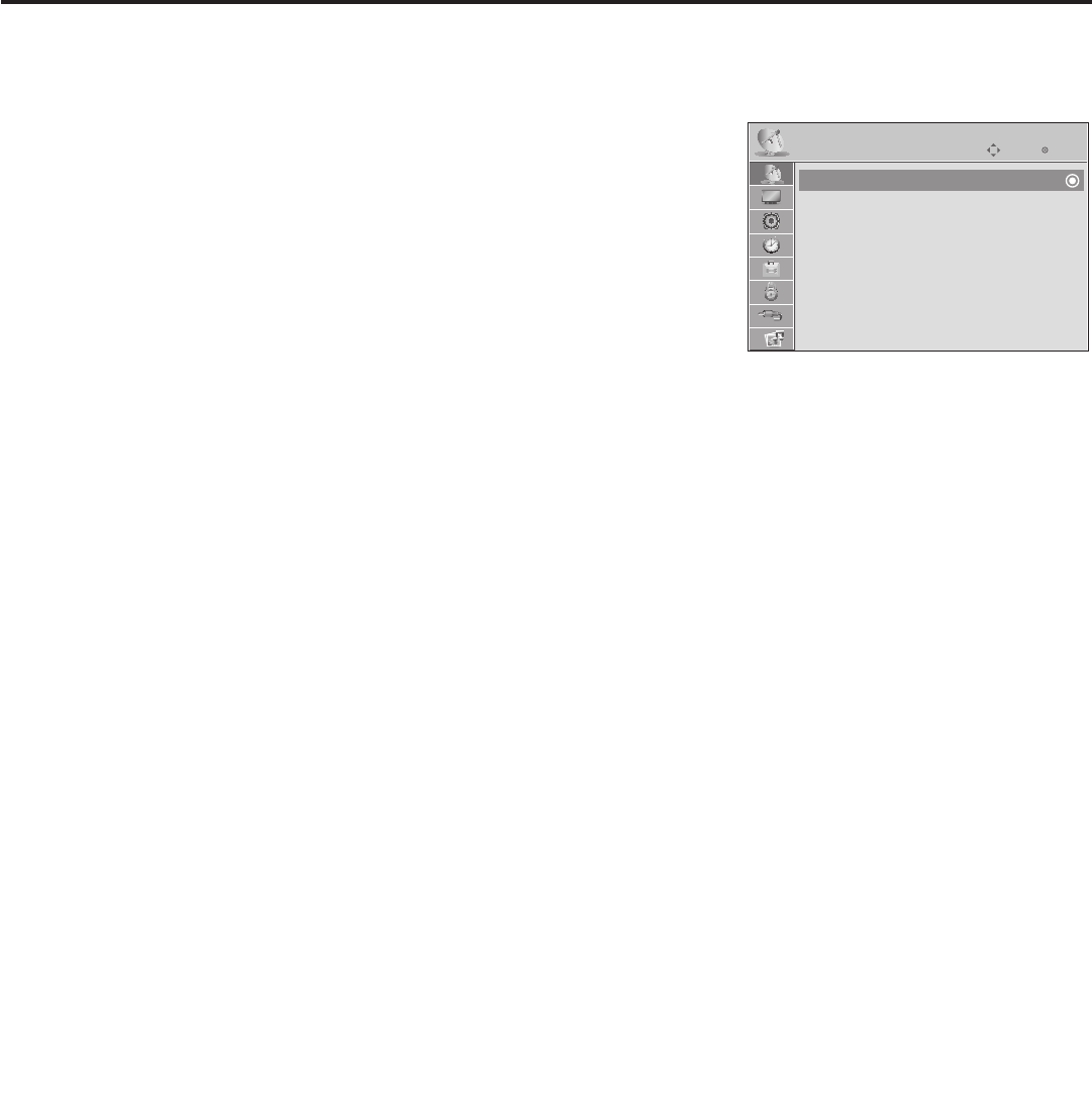
13
206-4200
Master TV Setup (Cont.)
(Continued from previous page)
3. (Optional) Run Auto Tuning.
Important: If you intend to use a USB memory device / .tlx file
for cloning purposes, DO NOT run Auto Tuning. If you Teach
a .tlx file with an auto-tuned/edited Channel Map to a Target
TV, this will put the Target TV in FTG Mode via CPU. If you
run Auto Tuning with the intension to clone the resulting
Channel Map, you must use a USB memory device / .tll file or
a clone programmer for this cloning purpose.
a) To search for all available analog and digital channels, go to the
Channel Menu, select the Auto Tuning option, and follow the
on-screen instructions.
b) Use the Channel Edit option in the Channel Menu to edit the
channel lineup, as necessary, to include only free to guest
(non-encrypted) channels.
• Add/delete channels per your system requirements.
(Optional) Use Channel Menu options
to run Auto Tuning, edit channels, and
select channel icons.
Enter
Move
CHANNEL
Auto Tuning
Manual Tuning
Channel Edit
Channel Label
(Continued on next page)
• Use the Channel Label option in the Channel Menu to select the appropriate
trademark/icon for each channel’s Channel-Time on-screen display. Icons are
available for familiar channels, such as ABC, CBS, NBC, etc. Identiable labels
(icons) should enable the end user to readily know what common networks are
available.
Note: If you intend to clone the PTC and Installer Menu item 103 ATSC TUNE
MODE is set for Physical Channel tuning (default and recommended setting),
channels with minor channel numbers higher than 255 will not transfer correctly
in step 5. If item 103 is set for Virtual Channel tuning and either the major or
minor channel numbers are higher than 255, the channel(s) will not transfer
correctly in step 5.
Note: If you intend to clone the PTC, you can add the channel icons in this step or
as described in step 6. Also in step 6, you can add custom text labels for channels
without icons.
4. Determine the next appropriate step according to the cloning method you
intend to use.
• If using a USB memory device / .tll le or a clone programmer: Continue with step
5. You must perform this step to transfer the TV setup menu settings to the PTC in
order to clone the PTC successfully.
• If using a .tlx le: Proceed to step 7 to verify the TV setup. (Steps 5 and 6 are not
applicable for .tlx les.)
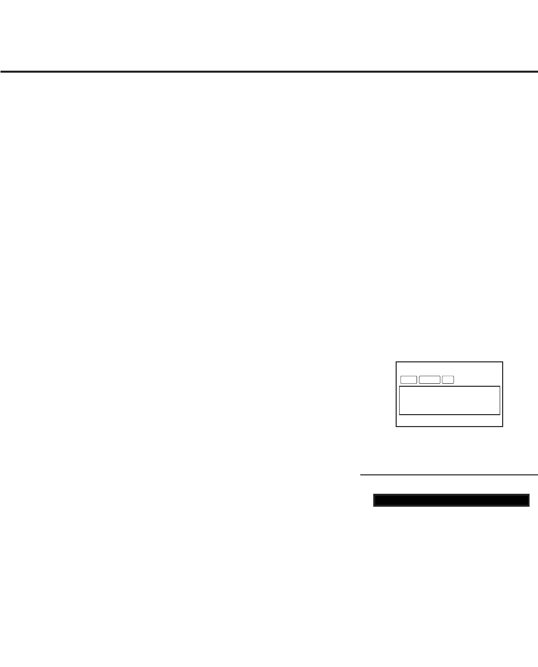
14 206-4200
6. (Optional) Add Custom Channel and Aux Labels:
2-5-4 + MENU Mode
Note: This step is applicable only if you intend to clone the PTC.
2-5-4 + MENU Mode enables you to add/edit channel icons and cus-
tom text labels in the PTC once the Master TV Setup has been trans-
ferred as described in the previous step.
Enter the Installer Menu, and press 2-5-4 + MENU on the Installer
Remote. Add/edit custom text labels and/or change icons for the
Channel-Time on-screen displays (see 2-5-4 + MENU procedural
information on page 23). Note that broadcast digital channels often
already have a broadcaster generated label. When you are finished,
press MENU to exit 2-5-4 + MENU Mode.
7. Verify the TV setup.
As applicable, verify that the channel lineup, channel icons, and custom
text labels are correct. Also, make sure the TV features are set per your
requirements.
8. Lock the channel lineup.
Enter the Installer Menu. Set item 028 CH. OVERIDE to 000 and
press ENTER to lock the channel lineup and restrict access to the TV
setup menus. Press ENTER again to save your changes and exit the
Installer Menu.*
The Master TV Setup is now ready to be copied to the predetermined
cloning tool—a USB memory device (.tlx or .tll le) or a clone programmer.
See cloning procedures in this document.
Master TV Setup (Cont.)
After verifying the TV Setup, set Installer
Menu item 028 CH. OVERIDE to 000.*
DIGITAL
WXYZ
MONO STEREO SAP
19-3
Custom text label “WXYZ” created
in 2-5-4 + MENU Mode.
* This step prevents end users from
accessing channel settings (i.e., the
Channel Menu will be inaccessible/
grayed out).
028 CH. OVERIDE 000
(Continued from previous page)
5. Transfer the TV setup menu settings to the commercial controller (PTC):
2-5-5 + MENU Mode
Important: This step is essential for successful cloning using a USB memory
device / .tll file or a clone programmer. Without this step, the PTC will not
contain any of the TV setup menu settings.
a) After the TV channel lineup has been edited and channel label icons added, tune to
the channel (source) for which you wish to transfer TV setup menu settings.
Note: If you intend to use a clone programmer for cloning purposes, this must be
either an analog channel or Aux input.
b) Enter the Installer Menu, and press 2-5-5 + MENU on the Installer Remote to
initiate the transfer of the Master TV Setup to the PTC. The TV exits the Installer
Menu and then tunes through the channels in the channel lineup during the
transfer. When the transfer is complete, the TV tunes back to the channel that
was tuned before the transfer began.
Note: The maximum number of channels that can be transferred is 141. An attempt to
transfer more than 141 channels will result in erratic TV tuning operation.

15
206-4200
Installer Menu
Typical Installer Menu
Use the Installer Menu to set up, change, or view operational settings.
Refer to the table starting on the next page for brief descriptions of Installer Menu items.
More detailed descriptions follow the table listing.
Accessing the Installer Menu
1. Make sure the TV is ON.
2. Using an Installer Remote, press MENU repeatedly until the on-
screen display of the TV setup menus (if the TV is in Pass-through
Mode) or the Function Menu (if the TV is not in Pass-through Mode)
no longer toggles, and then press 9-8-7-6 + ENTER to access the
Installer Menu.
The Installer Menu opens with item 000 INSTALLER SEQ 000.
Note: If the password is not entered or registered correctly, you will see
the message “ENTER PASSWORD 0000” at the top of the screen instead
of the Installer Menu header. Once you re-enter the correct password
(i.e., press 9-8-7-6 + ENTER), the Installer Menu will display.
Note: If the TV is in FTG Mode, the Installer Menu is accessible as read-
only. Refer to pages 33 to 43 for information on FTG Mode configuration.
xxLD66xH PTC INSTALLER MENU
000 INSTALLER SEQ 000
UPN 000-000-000-000 ASIC D27B
PTC V1.00.014 CPU V1.17.00
Using the Installer Menu
Refer to the table on pages 16 and 17 for an overview of the available Installer Menu items, including
their item numbers, functions, value ranges, and default values.
Installer Menu items not relevant to this TV series are not present in the Installer Menu; therefore,
some numbers are missing. For example, item 006 will not appear. In addition, items that are
dependent on other Installer Menu item settings will not be initially accessible. For example, item 046
STRT AUX SRCE will not display in the Installer Menu unless item 004 STRT CHANNEL is set to 0.
Navigation within the Installer Menu
Use the Up/Down arrow keys on the Installer Remote to sequence through the available menu items,
or access an item directly by keying in the item number and then pressing MENU. For example, to
access the SLEEP TIMER option, which is item 015, press 0-1-5 + MENU.
Changing Installer Menu Settings
To change an Installer Menu item value, use the Left/Right arrow keys on the Installer Remote, or
enter a valid value directly. To save the new setting, press ENTER, or use the Up/Down arrow keys
to navigate to a new Installer Menu item if you have additional items to edit. Note that invalid values
will not be saved.
Exiting the Installer Menu and Activating Updates
After you have adjusted all required Installer Menu item settings, press ENTER once on the Installer
Remote to save your changes; then, press ENTER again to exit the Installer Menu. Any changes you
make will be stored in non-volatile memory.
Note: Each time you exit the Installer Menu in Pass-through Mode, all V-Chip (Parental Control)
settings in the TV are reset to their default values; that is, the Lock System, if previously enabled
from the Lock setup menu (see the Owner’s Manual for additional information), will now be disabled,
and the individual Parental Control settings will be restored to default values.

16 206-4200
Installer Menu (Cont.)
Installer Menu Items 000 through 073
Menu
Item Function Value Range Default Value Brief Description of Function and Comments
000 INSTALLER SEQ 0 ~ 3 0 Leave default set to 0.
001 POWER MANAGE 0 ~ 7 0 Sets number of hours of no activity before automatic shutoff.
002 AC ON 0 / 1 0 Set to 1 to enable Auto Turn ON when AC power is applied.
003 BAND/AFC 0 ~ 3 1 Selects Tuning Band: 0=Broadcast, 1=CATV, 2=HRC, 3=IRC
004 STRT CHANNEL 0 ~ 127, 253,
255 255
Channel tuned when TV is turned ON. (Set to 255 to tune to channel
tuned before TV turned OFF.)
005 CHAN LOCK 0 / 1 0 If set to 1, cannot tune from current channel.
007 STRT VOLUME 0 ~ 63, 255 255 Volume level when TV is turned ON. (Set to 255 to use volume level
before TV turned OFF.)
008 MIN VOLUME 0 ~ 63 0 Sets minimum allowable volume setting.
009 MAX VOLUME 0 ~ 63 63 Sets maximum allowable volume setting.
010 MUTE DISABLE 0 / 1 0 Set to 1 to disable Mute Function.
011 KEY DEFEAT 0 / 1 0 Set to 1 to disable menu navigation keys on display panel.
015 SLEEP TIMER 0 / 1 1 Set to 1 to enable Sleep Timer.
016 EN TIMER 0 / 1 0 Set to 1 to enable On/Off Timers.
017 ALARM 0 / 1 1 Set to 1 to enable Alarm.
020 FEATURE LEVEL 0 ~ 1, 16 ~ 24 1 Determines an additional IR code scheme to which the TV will respond.
021 V-CHIP 0 / 1 1 Set to 1 to enable V-Chip (Parental Control) functions.
022 MAX BLK HRS 0 ~ 99 12 Sets number of V-Chip blocking hours.
023 CAPTION LOCK 0 / 1 0 Set to 1 to retain caption setting set before TV turned OFF.
028 CH. OVERIDE 0 / 1 1 If set to 0, limits direct access to favorite channels.
029 OLD OCV 0 / 1 0 Set to 1 to change MPI operation to OCV.
030 ACK MASK 0 / 1 0 If set to 1, enables ACK feature of MPI.
031 POLL RATE 20 ~ 169 94 Selects poll rate for MPI.
032 TIMING PULSE 186 ~ 227 207 Sets baud rate for MPI.
034 CAMPORT EN 0 / 1 1 Set to 1 to enable Video 2 input.
035 COMPPORT EN. 0 / 1 1 Set to 0 to disable HDMI 1. Set to 1 enable HDMI 1.
038 YPrPb EN. 0 / 1 1 Set to 1 to enable display panel Component Video 1 input jacks.
039 REAR AUX EN 0 / 1 1 Set to 1 to enable display panel Video 1 input jack.
040 AUTO CAMPORT 0 / 1 1 Set to 1 to automatically switch to Camport. If set to 1, STRT AUX SRCE
cannot be set to 2.
046 STRT AUX SRCE 1 ~ 6, 255 6 Sets the starting Aux source (if item 004 STRT CHANNEL is set to 0).
047 AUX STATUS 0 / 1 0 Set to 1 for MPI Aux source to be reported as a channel number instead of
Channel 0.
053 DIS. CH-TIME 0 / 1 0 Set to 1 to disable Channel-Time display.
069 EN. CH-T COL. 0 / 1 1 Set to 1 to enable custom color for the Channel-Time display.
070 FOR. CH-TIME 0 ~ 7 2 Chooses custom foreground color for the Channel-Time display.
071 BCK. CH-TIME 0 ~ 7 2 Chooses custom background color for the Channel-Time display.
073 CH NOT AVBLE 0 / 1 0 If set to 1 and item 028 CH. OVERIDE is set to 0, “NOT AVAILABLE” message
is displayed if user direct tunes a channel that is not in the favorite channel list.

17
206-4200
Installer Menu Items 075 through 122
Menu
Item Function Value Range Default Value Brief Description of Function and Comments
075 REVERT CH 0 / 1 0 If set to 1 and loss of MPI communication occurs, TV tunes to Start Channel.
078 UPN MSB 0 ~ 255 0 User programmable number, most significant byte.
079 UPN MSB-1 0 ~ 255 0 User programmable number, most significant byte - 1.
080 UPN MSB-2 0 ~ 255 0 User programmable number, most significant byte - 2.
081 UPN LSB 0 ~ 255 0 User programmable number, least significant byte.
082 CHKSM ERROR 0 / 1 1 If set to 1, enforces rigid MPI checksum.
083 HANDSHK TIME 0 ~ 5 5 Relaxes MPI timing to be compatible with PC-based Windows-
controlled systems.
084 PERMANENT BLK 0 / 1 0 Removes block hours setting for Parental Control and makes block permanent.
087 REAR RGB EN.
0
/
1
/
17
1 Dependent on item 093 RJP AVAILABLE setting. Set to 0 to disable RGB input.
Set to 1 to enable RGB input. Set to 17 for Auto Configure.
088 EN NOISE MUTE 0 / 1 1 If set to 1, audio is muted if no signal is present.
090 KEY LOCK 0 / 1 0 If set to 1, keyboard is locked out, IR is still functional.
091 YPrPb2 EN 0 / 1 1 Set to 1 to enable HDMI 2 input.
093 RJP AVAILABLE 0, 1, 2, 5, 6 0 Set to 0 to disable. Set to 1, 2, 5, or 6 for HDMI or DVI Mode. (See
detailed descriptions.)
094 SAP MENU EN 0 / 1 1 Set to 0 to disable feature on Function Menu. Set to 1 to enable feature on
Function Menu.
096 DEF. ASP. RATIO 0 ~ 4 2 Sets default aspect ratio at power up. See detailed descriptions and item 106.
098 PRO:CENTRIC
0 ~ 2
0
Set to 0 to disable Pro:Centric operation. Set to 1 for Flash Mode. Set to 2 for
GEM (Java Application) Mode.
099 BACK LIGHTING
1 ~ 100, 101 ~
200, 201, 202, 255
202
Sets the level of the TV picture back lighting. (See detailed descriptions.)
102 ATSC BAND 0 ~ 4 4 Selects ATSC band.
103 ATSC TUNE MODE 0 / 1 1 Set to 1 (default) for Physical Channel scan. Set to 0 for Virtual Channel scan.
104 START MINOR CH 0 ~ 255 0 Selects Minor Start Channel. Set to 0 for NTSC.
106 ASP RATIO LOCK 0 / 1 0 To retain set aspect ratio on power cycle, set to 1. Set to 0 for default ratio on
power cycle.
116 VIDEO MUTE EN 0 / 1 0 Set to 0 for Normal. Set to 1 for Blank.
117 FACT DEFAULT 0 / 1 0 Set to 0 for Normal. Set to 1 to load presets for all Installer Menu settings.
118 POWER SAVINGS 1 / 3 3 Set to 3 (default—b-LAN module only powered when TV is turned ON), or
set to 1 (b-LAN module is always powered). (See detailed descriptions.)
119 DATA CHANNEL 0 ~ 135, 253 0 Set to 0 to disable. Set to the RF channel number of the data channel for
Pro:Centric or TV E-Z Installation data. (See detailed descriptions.)
121 P:C RF WAKE HR 0 ~ 23, 128 128 Sets the hour for Wake On RF. The value “128” is displayed as “OFF.” Directly
entering 128 turns the Wake On RF feature OFF.
122 P:C RF WAKE MN 0 ~ 59 0 Sets the minute for Wake On RF.
Installer Menu (Cont.)
Caution: Installer Menu settings may affect options available
from the TV setup menus or the Function Menu.

18 206-4200
Installer Menu (Cont.)
Detailed Descriptions of Installer Menu Items
000 - INSTALLER SEQUENCE
Species entry sequence to the Installer Menu.
0 = 9876 1 = 4321
2 = 1478 3 = 3698
001 - POWER MANAGE (Power Management)
Determines hours of no activity before automatic shutoff. The
Power Management function is for saving energy. If set to 0,
Power Manage is Off. Settings range from 0 ~ 7, with 1 ~ 7
representing the hours that the unit will remain ON, unless there
has been activity from either the control panel or remote control.
002 - AC ON (AC Power Switchable)
If set to 1, this allows the TV to turn ON when AC power is applied.
Pressing the ON button is not necessary. This is desirable if the TV
is plugged into a cable box or a power outlet controlled by a wall
switch. Use the Left/Right arrow keys to choose 0 or 1, where 0 is
the default (OFF), and 1 is ON.
Note: If set to 1 (ON), the TV does not respond to ON/OFF
commands from either the remote or the display panel, and the
SLEEP TIMER is also nonfunctional.
003 - BAND/AFC (Band/Automatic Frequency Control)
There are four possible settings for this option:
0 = Broadcast 1 = CATV (default)
2 = HRC 3 = IRC
If some channels were not found by Auto Tuning (Channel
Search), select the appropriate Band setting here, and add the
channels using the Channel Edit option in the Channel Menu.
004 - STRT CHANNEL (Start Channel)
If active, this function allows you to determine the initial Major
Start Channel number when the TV is turned ON. This feature is
useful for an in-house information channel, since the TV would
always select that channel when it is turned ON. Setting this item
to 255 causes the last channel viewed when the TV was turned
OFF, to be the tuned to channel when the TV is turned ON again.
Note: For a digital Start Channel, always remember to set item
104 to the Minor Start Channel number.
Note: The IP Start Channel shown below can only be set in the
FTG File Manager, which is used to congure TV CPUs for FTG
Mode. The same applies for 2-byte tuning ranges (128 ~ 135 for
Physical 2-byte tuning and 128~999 for Virtual 2-byte tuning). This
means that these values, if set, will only be visible in the read-
only Installer Menu when the TV is in FTG Mode via CPU. The
read-only display also will show additional information about the
channel, for example, the IP address and port number, etc.
0 = Aux 127 = Map to Channel 4
1 ~ 125 = Major Ch. # 253 = IP Start Channel
126 = Map to Channel 3 255 = Last Channel
005 - CHAN LOCK (Channel Lock)
Channel Lock is ideal if the system must always be on the same
channel. Changing channels with the Channel Up/Down or keypad
numbers is impossible. Channel Lock is inactive if set to 0 (default).
Generally, this feature is used in connection with item 004 STRT
CHANNEL where the Start Channel may, for example, be set to
3 or 4. If the Start Channel is 3, then the TV will remain locked on
channel 3.
NOTE: For items 007, 008, and 009
For legacy reasons, the scale used is 0 – 63. The PTC software
will translate this to the 0 – 100 scale used by the TV.
To translate a TV volume level to the Installer Menu value, use
the following formula:
Installer Value = TV Value x 63
100
Enter only the whole number (disregard fractions).
007 - STRT VOLUME (Start Volume)
This function allows the Installer to determine the initial volume
level setting when the TV is turned ON. This feature is useful
for an in-house information channel, since the TV would always
select that volume level when it is turned ON. The range of values
are 0 - 63, 255. If 255 is selected, the current volume level will be
retained in memory when the TV is turned OFF; at turn ON, the
volume level will be automatically set at the previous or last level.
008 - MIN VOLUME (Minimum Volume)
This function determines the minimum volume level allowable
with the Volume (VOL) Up/Down control. In this way, for example,
someone cannot set the volume too low to hear. The value range
is from 0 to 63. Use the Left/Right arrow keys to change values.
The factory default is 0, which provides the full range of volume
control, if item 009 MAX VOLUME is also set to 63. It may be best
to set the same value on every TV.
Note: The minimum volume level cannot have a value setting
higher than the maximum volume level (described below).
009 - MAX VOLUME (Maximum Volume)
This function determines the maximum volume level allowable
with the Volume (VOL) Up/Down control. In this way, for example,
someone cannot set the volume level high enough to disturb
others. The value range is 0 to 63, with 63 as the default, which
gives the user the full range of volume control, if item 008 MIN
VOLUME is also set at 0. Use the Left/Right arrow keys to change
values. It may be best to set the same value on every TV.
Note: The maximum volume level cannot have a value setting
lower than the minimum volume level (described above).
19
206-4200
Installer Menu (Cont.)
010 - MUTE DISABLE
Enables or disables sound mute function. If set to 1, sound cannot
be muted. If set to 0, sound can be muted.
011 - KEY DEFEAT (Keyboard Defeat)
If set to 1, KEY DEFEAT prevents the end user from accessing
the on-screen menu(s) from the display panel—MENU, ENTER,
and menu navigation keys do not function. If set to 0, those keys
do function.
Note: Users can always access the menu(s) by pressing MENU
on the remote.
015 - SLEEP TIMER
If set to 1, the Sleep Timer feature may be used. If set to 0, the
Sleep Timer is not available.
016 - EN TIMER (Enable On/Off Timers)
If set to 1, the Timer function is available to the end user and
enabled continuously. Set to 0 to disable On/Off timers.
Note: Clock must be set in order for timers to be used.
017 - ALARM
Gives the installer the option of making the Alarm function avail-
able to the end user. If set to 1, the Alarm function is available to
the end user. Set to 0 to disable the Alarm function.
Note: Clock must be set before the Alarm function will work.
020 - FEATURE LEVEL
Determines an additional IR code scheme to which the TV will
respond, allowing for the use of unique IR codes based on “bed
number” in a multi-TV single room installation. First determine the
IR mode; then select the bed number.
IR Mode Bed # Values
Legacy (Hospital) 1 – 2 0 – 1
Multi-code Remote 1 – 9 16 – 24
Note: For further information, see documentation for the accessory
package that includes the multi-code remote.
021 - V-CHIP (Parental Control)
Set to 1 to activate V-Chip (Parental Control) and have it available
to the end user to lter and control or otherwise restrict program-
ming content that can appear. Set to 0 to turn the V-Chip feature
Off (not available to user); no programming restrictions can be set.
022 - MAX BLK HRS (Maximum Block Hours)
Sets hours from 0 to 99 for the maximum V-Chip (Parental Control)
block hours. Default setting is for 12 blocking hours.
Note: This item is not available in the Installer Menu unless item
084 PERMANENT BLK is set to 0.
023 - CAPTION LOCK
If set to 0, captions are OFF when the TV is turned ON. Set to 1 to
use the caption setting congured before the TV was turned OFF
when the TV is turned ON.
028 - CH. OVERIDE (Channel Override)
If set to 1, the user can select channels with either Channel Up/
Down or by direct keypad entry. If set to 0, only those channels
that are active in the TV’s memory can be selected.
029 - OLD OCV (On Command Video™)
Set to 1 for operation with systems from On Command Corporation.
030 - ACK MASK
MPI Communication Parameter. When set to 1, enables ACK
feature of MPI.
031 - POLL RATE
MPI Communication Parameter. Selects poll rate for MPI. Step
size of 16 ms. Changing from default may affect communication
via MPI.
032 - TIMING PULSE
MPI Communication Parameter. Sets baud rate for MPI. Step size
of 4.3 uS. Changing from default may affect communication via
MPI.
034 - CAMPORT EN. (Camera Port Enable)
Set to 1 to enable Video 2 input on display panel. If set to 0, Video
2 input on display panel is not functional.
035 - COMPPORT EN. (Computer Port Enable)
Enable/disable TV display panel HDMI 1 input jack. Set to 0 to
disable HDMI 1. Set to 1 to enable HDMI 1.
Note: This setting is ignored if item 093 RJP AVAILABLE is set to 1.
038 - YPrPb EN. (Rear Component Video Enable)
Set to 1 to enable display panel rear Component Video input jacks.
Set to 0 to disable display panel rear Component Video input jacks.
039 - REAR AUX EN. (Rear Aux Enable)
Set to 1 to enable display panel rear Aux (Video 1) input. Set to 0
to disable display panel rear Aux (Video 1) input.
040 - AUTO CAMPORT
Set to 1 to automatically switch to Camport when equipment is
connected to front Video input. Set to 0 to disable front Video
automatic source selection. If set to 1, STRT AUX SRCE cannot
be set to 2.
Note: If set to 1, item 093 RJP AVAILABLE is automatically set to 0.

20 206-4200
Installer Menu (Cont.)
046 - STRT AUX SRCE (Start Aux Source)
Sets the starting Aux source. When turned ON, the TV will tune to
starting Aux source if item 004 STRT CHANNEL is set to 0.
If item 093 RJP AVAILABLE is set to 0 and item 040 AUTO
CAMPORT is set to 0:
1 = Video 1 4 = RGB 255 = Last Aux
2 = Video 2 5 = HDMI 2
3 = HDMI 1 6 = Component
If item 093 RJP AVAILABLE is set to 1:
2 = Video 2 5 = HDMI 2 6 = Component
If item 040 AUTO CAMPORT is set to 1:
1 = Video 1 4 = RGB 6 = Component
3 = HDMI 1 5 = HDMI 2
Note: This item is not available in the Installer Menu unless item
004 STRT CHANNEL is set to 0.
047 - AUX STATUS
Set to 1 for MPI Aux source to be reported as a channel number
instead of channel 0. Set to 0 to disable Aux identication change.
Controls MPI status channel response for Aux inputs.
053 - DIS. CH-TIME (Disable Channel-Time)
Set to 1 to disable the Channel-Time display; Channel-Time
display will not appear. Set to 0 to enable the Channel-Time
display.
069 - EN. CH-T COL. (Enable Channel-Time Custom Color)
Set to 1 to enable custom color for the Channel-Time display. Set
to 0 to disable custom color for the Channel-Time display.
070 - FOR. CH-TIME (Channel-Time Display Foreground Color)
Set according to Color Chart:
0 = Black 3 = Cyan 6 = Yellow
1 = Blue 4 = Red 7 = White
2 = Green 5 = Violet
Note: If foreground color and background color are the same, the
menu background will be transparent.
Note: Applies only to “Channel Not Available” message if item
073 CH NOT AVBLE is set to 1 (enabled). Also, items 070 FOR.
CH-TIME and 071 BCK. CH-TIME are not available in the Installer
Menu when item 069 EN. CH-T COL. is set to 0.
071 - BCK. CH-TIME (Channel-Time Display Background Color)
See description for item 070 FOR. CH-TIME above. The color
chart is the same for both items.
073 - CH NOT AVBLE (Channel Not Available)
If set to 1 and item 028 CH. OVERIDE is set to 0, a “NOT AVAIL-
ABLE” message is displayed when a user direct tunes a channel
that is not in the channel scan list available in memory.
075 - REVERT CH (Revert to Start Channel)
If set to 1 and loss of MPI communication occurs, TV automatically
tunes to the specied Start Channel.
Note: This item is not available in the Installer Menu when item
004 STRT CHANNEL is set to 255.
078 - UPN MSB (UPN Most Signicant Byte)
User programmable number, most signicant byte readable by
MPI command. Note: Not linked to serial number.
079 - UPN MSB-1 (UPN Most Signicant Byte-1)
User programmable number, most signicant byte-1 readable by
MPI command. Note: Not linked to serial number.
080 - UPN MSB-2 (UPN Most Signicant Byte-2)
User programmable number, most signicant byte-2 readable by
MPI command. Note: Not linked to serial number.
081 - UPN LSB (UPN Least Signicant Byte)
User programmable number, least signicant byte readable by
MPI command. Note: Not linked to serial number.
082 - CHKSM ERROR (Checksum Error)
Enforces rigid MPI checksum validation. Set to 1 for validation.
Set to 0 to disable (does not check checksum on MPI async port).
SPI is always checked.
083 - HANDSHK TIME (Handshake Time)
Adds an additional delay to the handshake time which is 64 msec,
thus relaxing MPI timing requirements to be compatible with PC-
based Windows controlled systems. Range is 0 - 5.
(Timeout = 25.5MS + [25.5 MS* Handshake time].)
084 - PERMANENT BLK (Permanent Block)
Allows Lock (Parental Control) blocking schemes to be permanent
by disabling the blocking hours function. Set to 1 to install Parental
Control restrictions permanently. Set to 0 for user-specied hours
control of blocking schemes.
087 - REAR RGB EN. (Rear RGB Enable)
Controls access to rear RGB input on TV. Set to 0 to disable RGB
input. Set to 1 to enable RGB input. Set to 17 to initiate a one-
time automatic conguration after an AC power cycle; otherwise,
automatic adjustment will be performed each time the RGB input
is accessed.

21
206-4200
088 - EN NOISE MUTE (Enable Noise Mute)
If set to 1, audio mutes when no signal is present.
090 - KEY LOCK
If set to 1, display panel Channel, Volume, and Caption buttons
are disabled, Power button remains enabled. If set to 0, Channel,
Volume, Caption, and Power buttons are all enabled.
091 - YPrPb2 EN. (HDMI2 Enable)
Set to 1 to enable display panel HDMI 2 input. Set to 0 to disable
display panel HDMI 2 input.
093 - RJP AVAILABLE (Remote Jack Pack Available)
• 0 = Remote jack pack is not available or disabled.
• 1 = Legacy Model RJPs: HDMI Mode
Enables RJP feature for use with full cable bundle models. In
this mode, when an HDMI source is connected to the RJP, both
digital video and audio are expected via the HDMI cable. If no
digital audio is present, no audio will be heard.
• 2 = Legacy Model RJPs: DVI Mode
Enables RJP feature for use with full cable bundle models. In
this mode, when an HDMI/DVI source is connected to the RJP,
only digital video is expected via the HDMI cable. Analog audio
is provided via a separate cable, from the source, connected to
an RJP AUDIO IN. If no analog audio cable is connected, tuner
audio will be heard.
• 5 = Scaler Model RJPs: HDMI Mode
Enables RJP feature for use with reduced cable bundle models.
In this mode, when an HDMI source is connected to the RJP,
both digital video and audio are expected via the HDMI cable. If
no digital audio is present, no audio will be heard.
• 6 = Scaler Model RJPs: DVI Mode
Enables RJP feature for use with reduced cable bundle models.
In this mode, when an HDMI/DVI source is connected to the
RJP, only digital video is expected via the HDMI cable. Analog
audio is provided via separate cable, from the source, connect-
ed to an RJP AUDIO IN. If no analog audio cable is connected,
tuner audio will be heard.
Notes:
See Reference section, “RJP Model List and Input Auto-sensing
Hierarchy.” If RJP AVAILABLE is set to 1, 2, 5, or 6, item 040
AUTO CAMPORT is automatically set to 0. Settings 1, 2, 5, and 6
allow the lodge staff to customize each TV’s RJP setup based on
customer requirements.
094 - SAP MENU EN (2nd Audio Program)
Set to 1 to enable SAP feature on Function Menu, if Function
Menu is available (i.e., TV is not in Pass-through Mode). Set to
0 to disable SAP feature on Function Menu, if Function Menu is
available.
096 - DEF. ASP. RATIO (Default Aspect Ratio)
Selects default aspect ratio at power up.
• Set to 0 for Set By System.
• Set to 1 for 4:3.
• Set to 2 for 16:9 (Factory Default).
• Set to 3 for Just Scan.
• Set to 4 for Zoom.
Note: This item is not available in the Installer Menu unless item
106 ASP RATIO LOCK is set to 0.
098 - PRO:CENTRIC
Selects the Pro:Centric Application Mode. Set to 0 (default) to
disable Pro:Centric operation. Set to 1 for Flash Mode. Set to 2
for GEM (Java Application) Mode.
Note: This item is not available in the Installer Menu when item
119 DATA CHANNEL is set to 0.
Note: When both Pro:Centric items (098 PRO:CENTRIC and 119
DATA CHANNEL) are set, once you exit the Installer Menu, the
Function Menu will be available to end users instead of the TV
setup menus. Also, only the Learn From TV (TLX) option will be
available from the USB Download Menu; the Teach to TV option
will not.
099 - BACK LIGHTING
Sets the TV screen brightness at power up. Default setting is 202.
• 1 - 100 Static Back Lighting
(1 = Dimmest picture, 100 = Brightest picture)
• 101 - 200 Dynamic Back Lighting
(101 = Dimmest picture, 200 = Brightest picture)
• 201 Automatic Static Back Lighting
• 202 Automatic Dynamic Back Lighting
If set between 101 and 200, the TV automatically controls back
lighting depending upon the picture level of the current program. If
set to 201, the TV automatically controls back lighting depending
upon external spectral sensitivity. If set to 202, the TV automati-
cally controls back lighting depending upon external spectral
sensitivity and the picture level of the current program. If set to
255, back lighting is controlled via the Picture settings in the TV’s
setup menus.
102 - ATSC BAND
Sets up TV to receive different types of incoming signals:
0 = Broadcast, 1 = CATV, 2 = HRC, 3 = IRC, 4 = Same as NTSC.
103 - ATSC TUNE MODE
Sets ATSC tuning mode: Default set to 1 for Physical Channel
scan. Set to 0 for Virtual Channel scan.
Installer Menu (Cont.)

22 206-4200
104 - START MINOR CHANNEL
Sets Minor Start Channel number at power up. 0 = NTSC. If not
0, number selected is the digital channel’s Minor Start Channel
number.
Note: This item is not available in the Installer Menu when item
004 STRT CHANNEL is set to 0, 253, or 255.
106 - ASP RATIO LOCK (Aspect Ratio Lock)
Set to 1 to retain previous aspect ratio with power off. Set to 0 to
retain default aspect ratio with power off. See item 096 DEF. ASP.
RATIO above.
116 - VIDEO MUTE EN (Video Mute Enable)
Set to 0 for Normal. Set to 1 for Blank.
117 - FACT DEFAULT (Factory Default)
Set to 0 for normal. Set to 1 to load presets of all Installer Menu
item settings.
Caution: If set to 1, this will reload the factory
defaults and clear the channel lineup, including any
assigned channel icons and custom text labels.
Note: See also Reference section, “Resetting Factory Defaults on
the TV(s),” for further information.
118 - POWER SAVINGS
Default set to 3—the power circuitry for both the embedded b-LAN
module and the GAME CONTROL/MPI port is only powered when
the TV is turned ON. When the TV is in Standby Mode, the MPI
card slot is powered by the Standby power supply and both the
embedded b-LAN and the GAME CONTROL/MPI port are not
powered. When the TV is in Power On Mode, the MPI card slot is
powered by the main 12V power supply and both the embedded
b-LAN and GAME CONTROL/MPI port are powered.
Note that the TV must be turned ON in order to communicate with
the embedded b-LAN module for conguration and control when
POWER SAVINGS is set to 3. If set to 1, the b-LAN module is
always powered.
Similarly, if MPI communication is required for external MPI
control, POWER SAVINGS should be set to 1 so that the GAME
CONTROL/MPI port circuitry is always powered.
Note: MPI cards with b-LAN technology—LMT7Z5, LMT7Z7,
LMT7Z9—are NOT supported on TVs in which b-LAN technology
is already integrated.
Note: See Reference section, “b-LAN Setup & Overview,” for
further information.
119 - DATA CHANNEL
Set to 0 (default) to disable. Set to the RF channel number of the
data channel for Pro:Centric or TV E-Z Installation (splash screen,
configuration, and firmware) data.
The TV may take several minutes to load EPG data after AC
power is initially applied.
Note: The data channel is automatically set to 253 if Media Type
is set to IP in the Pro:Centric Menu on the TV (see “Pro:Centric
Setup” on page 45) or if Data Channel is set to IP Address in the
FTG File Manager, which is used to congure TV CPUs for FTG
Mode operation. It is not possible to change the value to “253”
directly.
121 - P:C RF WAKE HR
Set the hour from 0 to 23 for Wake On RF. This item uses the
24-hour clock format. The value “128” is displayed as “OFF.”
Directly entering 128 turns the Wake On RF feature OFF.
Note: This item is not available in the Installer Menu if item 119
DATA CHANNEL is set to 0 or 253.
122 - P:C RF WAKE MN
Set the minute from 0 to 59 for Wake On RF.
Note: This item is not available in the Installer Menu if item 119
DATA CHANNEL is set to 0 or 253 or if item 121 P:C RF WAKE
HR is set to 128/OFF.
Installer Menu (Cont.)
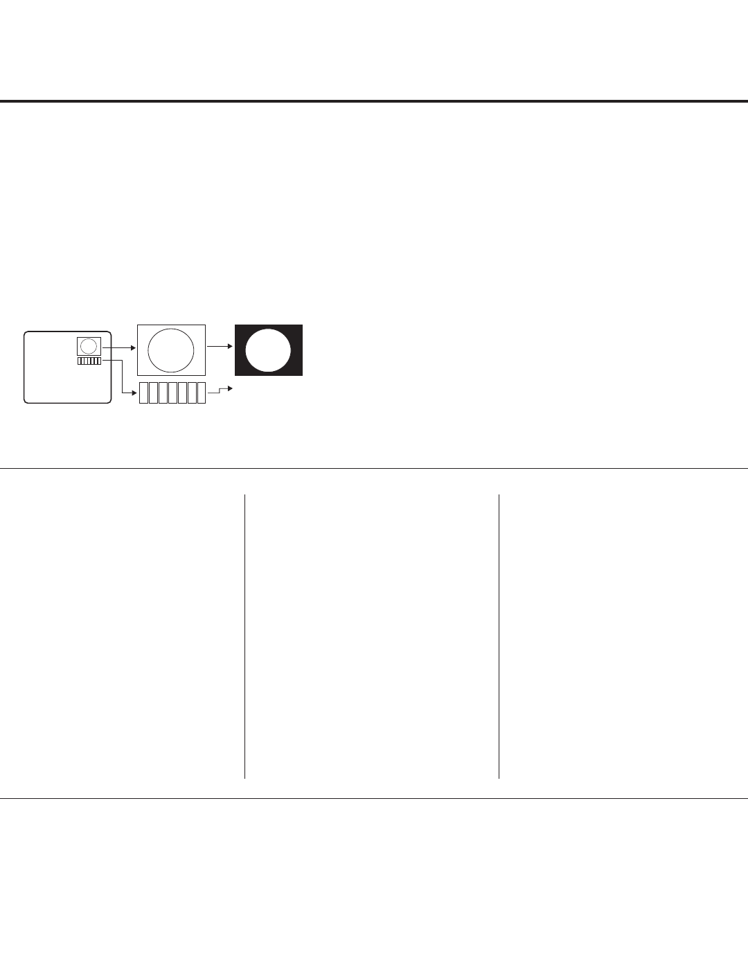
23
206-4200
Channel Icons / Custom Text Labels (2-5-4 + MENU Mode)
Changing a Channel’s Icon on
the Master TV
1. Use Channel Up/Down to select
the desired channel.
2. Use the Left/Right arrow keys
to select the thin letter “I” on the
Channel-Time display.
3. Use the Up/Down arrow keys to
select the icon with which you want
to identify the channel. (If you know
the icon number, enter the number,
and press ENTER.)
4. Proceed to add/edit custom text
labels, or go to the next channel.
Adding/Editing Channel Labels
on the Master TV
1. Use Channel Up/Down to select
the desired channel.
2. Press the Left or Right arrow
repeatedly until the numbers 1 to 7
appear on the display. The number
shows the position of the character
that can be changed. Number 1 is
the rst character, number 2 the
second character, etc.
3. Use the Up/Down arrow keys to
select the desired character.
4. Proceed to the next number posi-
tion, or go to the next channel.
Adding/Editing Source Labels
on the Master TV
1. Press INPUT to select the desired
Aux input source: AV1, AV2, RGB,
Component, HDMI, or HDMI2.
2. Press the Left or Right arrow
repeatedly until the numbers 0 to 9
appear on the display. The number
shows the position of the character
that can be changed.
3. Use the Up/Down arrow keys to
select the desired character.
4. Press INPUT for the next Aux input,
or use Channel Up/Down to return
to channels.
• Channel Up/Down: Tunes to the next channel in scan.
• Left/Right Arrows: Select the item to change. If “I” is
shown, the icon can be changed. If a number is shown, it
indicates the position of the character that can be changed.
• Up/Down Arrows: Select the icon or the character to be
displayed. Tip: Arrows can be held down for fast scrolling.
• 0 – 9: Use to enter the index number of the icon, if
known.
• ENTER: Changes the icon after the icon number has
been entered.
• INPUT: Changes the Aux input label.
• MENU: Exits the editing process.
Installer Remote Control Key Functions for Master TV Channel Label Editing Menu
Changing Channel Icons and/or Adding or Editing
Custom Text Labels in the Channel-Time Display
If there is no pre-assigned icon for a channel, you can add
a custom text label of up to seven (7) characters to help
identify the channel or network. Also, if desired, a custom
text label can be added to the Channel-Time display in
addition to a pre-assigned icon. You may also add text
labels for the Aux input sources to clearly identify the
devices that are connected to the Aux inputs.
Changing icons and/or adding or editing custom text labels
can only be done if there are channels that have been
transferred to the TV’s PTC either during Master TV Setup
(see pages 11 to 14) or by cloning (USB memory device /
.tll file or clone programmer only).
Note: A blank letter space is available between “Z” and “!”.
To perform channel editing/labeling:
1. Enter the Installer Menu: Press MENU repeatedly until
the on-screen display of the TV setup menus no longer
toggles, and then press 9-8-7-6 + ENTER.
2. Press 2-5-4 + MENU on the Installer Remote to enter
the Channel Label Editing Menu.
3. Change channel icons and/or add or edit custom text
labels as described in the procedures below. (You can
do this more than once.)
4. To exit the menu when you are done, press MENU.
1234567
XYZ
XYZ XYZ
NETWORK
(Icon)
(Custom Text Label)
24 206-4200
Cloning Overview
IMPORTANT CLONING INFORMATION
Starting with these TV models, there are now four different procedures for cloning a Master TV Setup,
each with its own advantages and limitations (see also “Cloning Methods” on page 11):
• Using a USB memory device / .tlx le
• Using a USB memory device / .tll le
• Using a TLL-1100A clone programmer
• Using a LT2002 clone programmer
Each cloning method is described in further detail on the pages that follow. As you perform cloning proce-
dures, be sure to complete each task as indicated. If a procedure or step is omitted or not performed
completely, cloning may not work. At each step, pay attention to ensure the TV screen shows the proper
message when cloning. If the message indicated does not appear, there is a problem with that step, and
cloning may not be successful.
Caution: Copying a blank or incorrect memory into a TV from a clone programmer will
cause the TV to operate erratically or become inoperable.
Caution: Do not connect a clone programmer to a PPV card installed in the Master or
Target TVs. Also, if the TV is in LodgeNet PPV Mode (check with the site administrator if
you are not certain), do not connect a clone programmer to the GAME CONTROL/MPI port.
Either of these actions will damage the clone programmer and, if applicable, the PPV card.
Before you begin cloning:
• Complete the Master TV Setup procedure (see pages 11 to 14).
• All equipment should be connected to power and turned ON.
• Both the Master and Target TVs must be in Pass-through Mode.
• Learning and Teaching is only possible between identical model TVs.
• If using a USB memory device, ensure the USB device has been formatted with FAT format.
• If using a USB memory device / .tlx le, ensure that the Master TV Setup does not contain a Channel Map;
otherwise, Teaching will result in the Target TV(s) being congured for FTG Mode via CPU.
• For both Master and Target TVs—If using a clone programmer, ensure the TV is tuned to either an Aux
input or an analog (not a digital) channel.
• LT2002 only—Make sure the batteries in the clone programmer are fresh. If batteries are removed, the
clone programmer clock time (if set) will be lost (see page 32 for information on the clone programmer
clock).
Caution: Do not unplug the TV power cord or remove/disconnect the USB memory device/
clone programmer while Learning or Teaching, as doing so may cause the TV to malfunction
or harm the USB device/clone programmer, respectively.
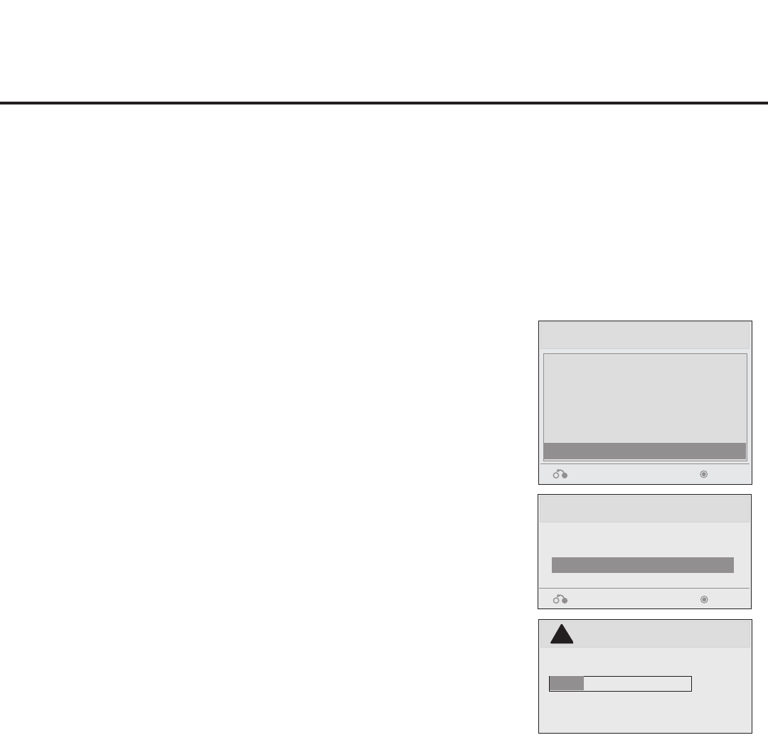
25
206-4200
USB Cloning Procedures
Learning / Teaching a Master TV Setup using a USB Memory Device / .tlx File
USB Cloning Notes
• Read the IMPORTANT CLONING INFORMATION on page 24 before beginning any cloning procedures.
In particular, ensure that the Master TV Setup does not contain a Channel Map; otherwise, Teaching will
result in the Target TV(s) being congured for FTG Mode via CPU.
• You may edit the lename as part of the Learning procedure; however, a le with edited contents will not
be recognized.
• It is not possible to clone a Master TV’s clock using a USB memory device. Either set a Target TV’s
clock manually, or use the Auto Clock setting in the TV setup menus.
Learn From TV (TLX)
Select the le name and press OK to start
xxLD660H-UA00003.TLX
Return
Enter
►
►
USB Download Menu
Upgrade TV Software
Upgrade PTC Software
Teach To TV (TLL)
Teach To TV (TLX)
Learn From TV (TLL)
Learn From TV (TLX)
Return Enter
Learn From TV
UPDATING...
Do not remove the USB from the port!
Do not unplug!
!
25%
Learn Setup from Master TV
1. Ensure the Master TV is set up completely and in Pass-through
Mode.
2. Plug the USB memory device into the USB IN port on the Master
TV.
3. Press MENU on the Installer Remote to display the TV setup
menus. Use the arrow navigation keys to select/highlight the
Option menu icon, and then press the number “7” key a total of
seven times to display the USB Download Menu.
4. To gain access to the “Learn From TV” option in the USB
Download Menu, key in the password used to enter the Installer
Menu (Example: Press 9-8-7-6).
5. Use the Up/Down arrow keys to select Learn From TV (TLX), and
then press ENTER.
6. To differentiate this .tlx le from others, you can use the Up/Down
arrow keys to change the last ve digits of the lename. Press
ENTER when you are ready to initiate Learning.
Learning status will be shown on the progress bar. When the
Learning process is complete, the USB Download menu will
reappear on screen.
7. When Learning is done, remove the USB memory device from the
Master TV.
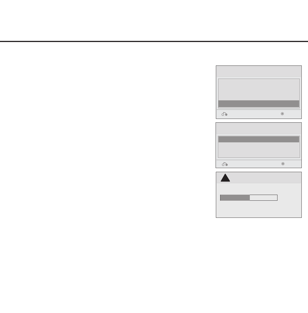
26 206-4200
USB Cloning Procedures (Cont.)
Learning / Teaching a Master TV Setup using a USB Memory Device / .tlx File (Cont.)
Teach Master TV Setup to Target TV
1. Ensure the Target TV is in Pass-through Mode, and then use the
Installer Remote to enter the Target TV Installer Menu: Press
MENU repeatedly until the on-screen display of the TV setup
menus no longer toggles, and then press 9-8-7-6 + ENTER.
2. Set Installer Menu item 117 FACT DEFAULT to 001, and press
ENTER. When the value changes back to 0, press ENTER again
to exit the Installer Menu.
3. Plug the USB memory device with the .tlx le into the Target TV
USB IN port.
4. Press MENU on the Installer Remote to display the TV setup
menus. Use the arrow navigation keys to select/highlight the
Option menu icon, and then press the number “7” key a total of
seven times to display the USB Download Menu.
5. Use the Up/Down arrow keys to select Teach To TV (TLX), and
then press ENTER.
6. Use the Up/Down arrow keys to select the Master TV Setup you
want to install, and then press ENTER. Note: Filenames identify
the TV and the TLX version (see example at right).
Teaching status will be shown on the progress bar. When the
Teaching process is complete, the USB Download menu will
reappear on screen.
7. When Teaching is done, remove the USB memory device from
the Target TV, turn OFF the TV, and unplug the TV power cord for
15 seconds.
8. Reconnect the TV power cord, and turn ON the TV. The Master
TV Setup should be resident on the Target TV.
Teach To TV (TLX)
xxLD660H-UA00003.TLX
Return Enter
USB Download Menu
Upgrade TV Software
Upgrade PTC Software
Teach To TV (TLL)
Teach To TV (TLX)
Return Enter
Teach To TV
UPDATING...
Do not remove the USB from the port!
Do not unplug!
!
50%
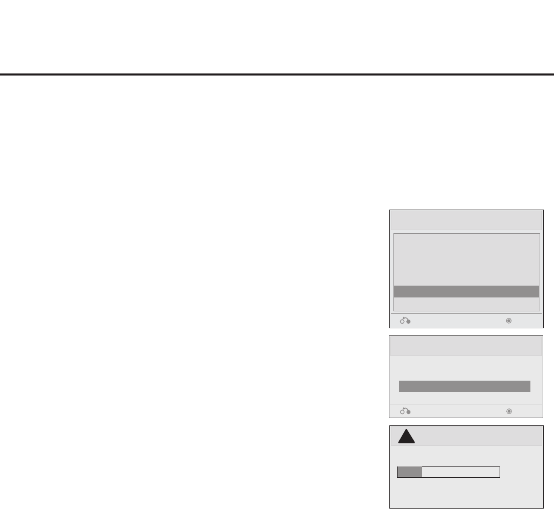
27
206-4200
USB Cloning Procedures (Cont.)
Learning / Teaching a Master TV Setup using a USB Memory Device / .tll File
USB Cloning Notes
• Read the IMPORTANT CLONING INFORMATION on page 24 before beginning any cloning procedures.
• You may edit the lename as part of the Learning procedure; however, a le with edited contents will not
be recognized.
• It is not possible to clone a Master TV’s clock using a USB memory device. Either set a Target TV’s
clock manually, or use the Auto Clock setting in the TV setup menus.
Learn From TV (TLL)
Select the le name and press OK to start
xxLD660H-UA00001.TLL
Return
Enter
►
►
USB Download Menu
Upgrade TV Software
Upgrade PTC Software
Teach To TV (TLL)
Teach To TV (TLX)
Learn From TV (TLL)
Learn From TV (TLX)
Return Enter
Learn From TV
UPDATING...
Do not remove the USB from the port!
Do not unplug!
!
25%
Learn Setup from Master TV
1. Ensure the Master TV is set up completely and in Pass-through
Mode.
2. Plug the USB memory device into the USB IN port on the Master
TV.
3. Press MENU on the Installer Remote to display the TV setup
menus. Use the arrow navigation keys to select/highlight the
Option menu icon, and then press the number “7” key a total of
seven times to display the USB Download Menu.
4. To gain access to the “Learn From TV” option in the USB
Download Menu, key in the password used to enter the Installer
Menu (Example: Press 9-8-7-6).
5. Use the Up/Down arrow keys to select Learn From TV (TLL), and
then press ENTER.
6. To differentiate this .tll le from others, you can use the Up/Down
arrow keys to change the last ve digits of the lename. Press
ENTER when you are ready to initiate Learning.
Learning status will be shown on the progress bar. When the
Learning process is complete, the USB Download menu will
reappear on screen.
7. When Learning is done, remove the USB memory device from the
Master TV.
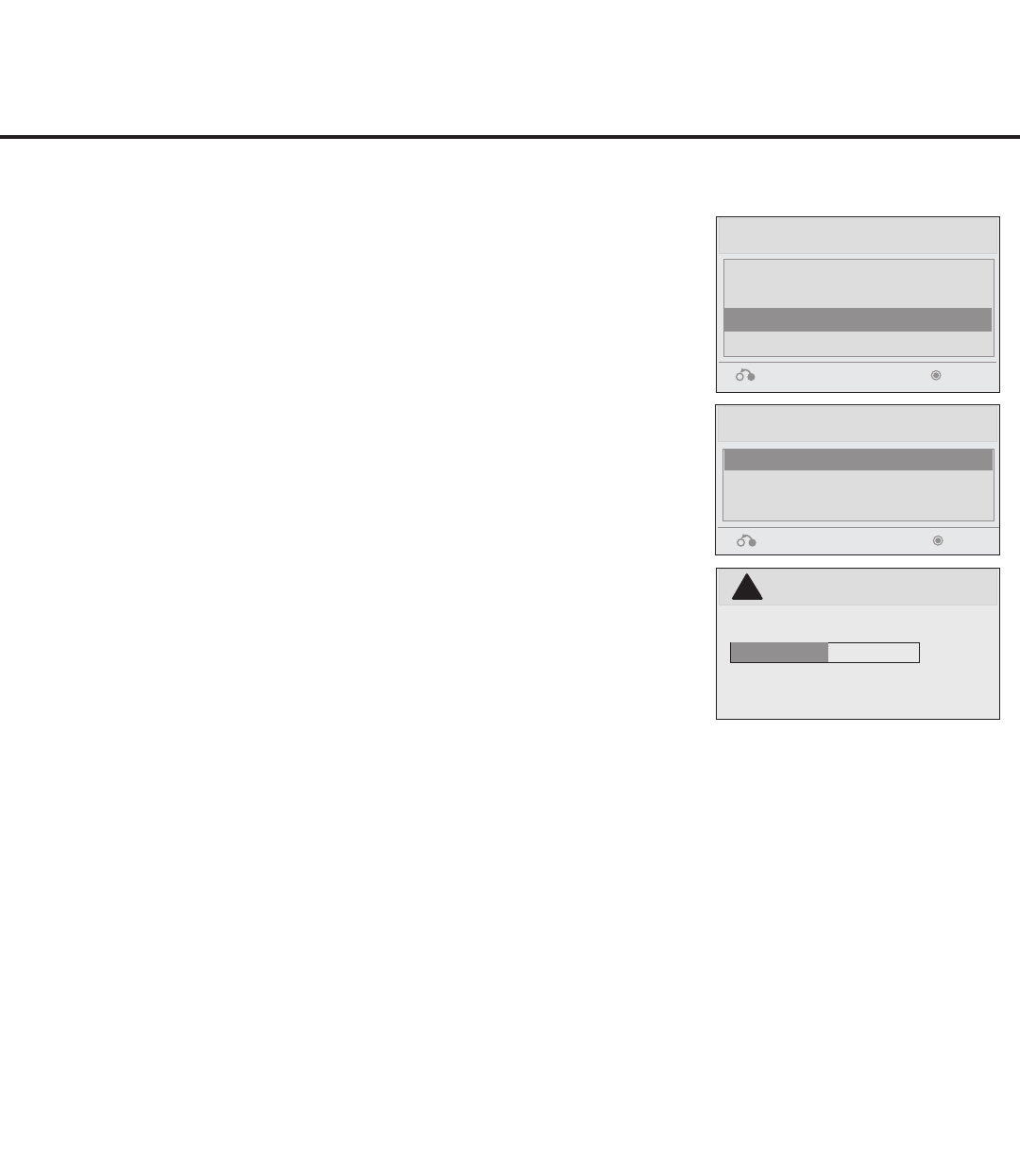
28 206-4200
Teach To TV (TLL)
xxLD660H-UA00001.TLL
Return Enter
USB Download Menu
Upgrade TV Software
Upgrade PTC Software
Teach To TV (TLL)
Teach To TV (TLX)
Return Enter
Teach To TV
UPDATING...
Do not remove the USB from the port!
Do not unplug!
!
50%
USB Cloning Procedures (Cont.)
Learning / Teaching a Master TV Setup using a USB Memory Device / .tll File (Cont.)
Teach Master TV Setup to Target TV
1. Ensure the Target TV is in Pass-through Mode, and then use the
Installer Remote to enter the Target TV Installer Menu: Press
MENU repeatedly until the on-screen display of the TV setup
menus no longer toggles, and then press 9-8-7-6 + ENTER.
2. Set Installer Menu item 117 FACT DEFAULT to 001, and press
ENTER. When the value changes back to 0, press ENTER again
to exit the Installer Menu.
3. Tune/set the TV to an analog or digital channel or Aux input, (ideally
the same source tuned for 2-5-5 + MENU Mode during the Master
TV Setup procedure).
4. Plug the USB memory device with the .tll le into the Target TV
USB IN port.
5. Press MENU on the Installer Remote to display the TV setup
menus. Use the arrow navigation keys to select/highlight the
Option menu icon, and then press the number “7” key a total of
seven times to display the USB Download Menu.
6. Use the Up/Down arrow keys to select Teach To TV (TLL), and
then press ENTER.
7. Use the Up/Down arrow keys to select the Master TV Setup you
want to install, and then press ENTER. Note: Filenames identify
the TV and the TLL version (see example at right).
Teaching status will be shown on the progress bar. When the
Teaching process is complete, the USB Download menu will
reappear on screen.
8. When Teaching is done, remove the USB memory device from
the Target TV, turn OFF the TV, and unplug the TV power cord for
15 seconds.
9. Reconnect the TV power cord, and turn ON the TV. The Master
TV Setup should be resident on the Target TV.
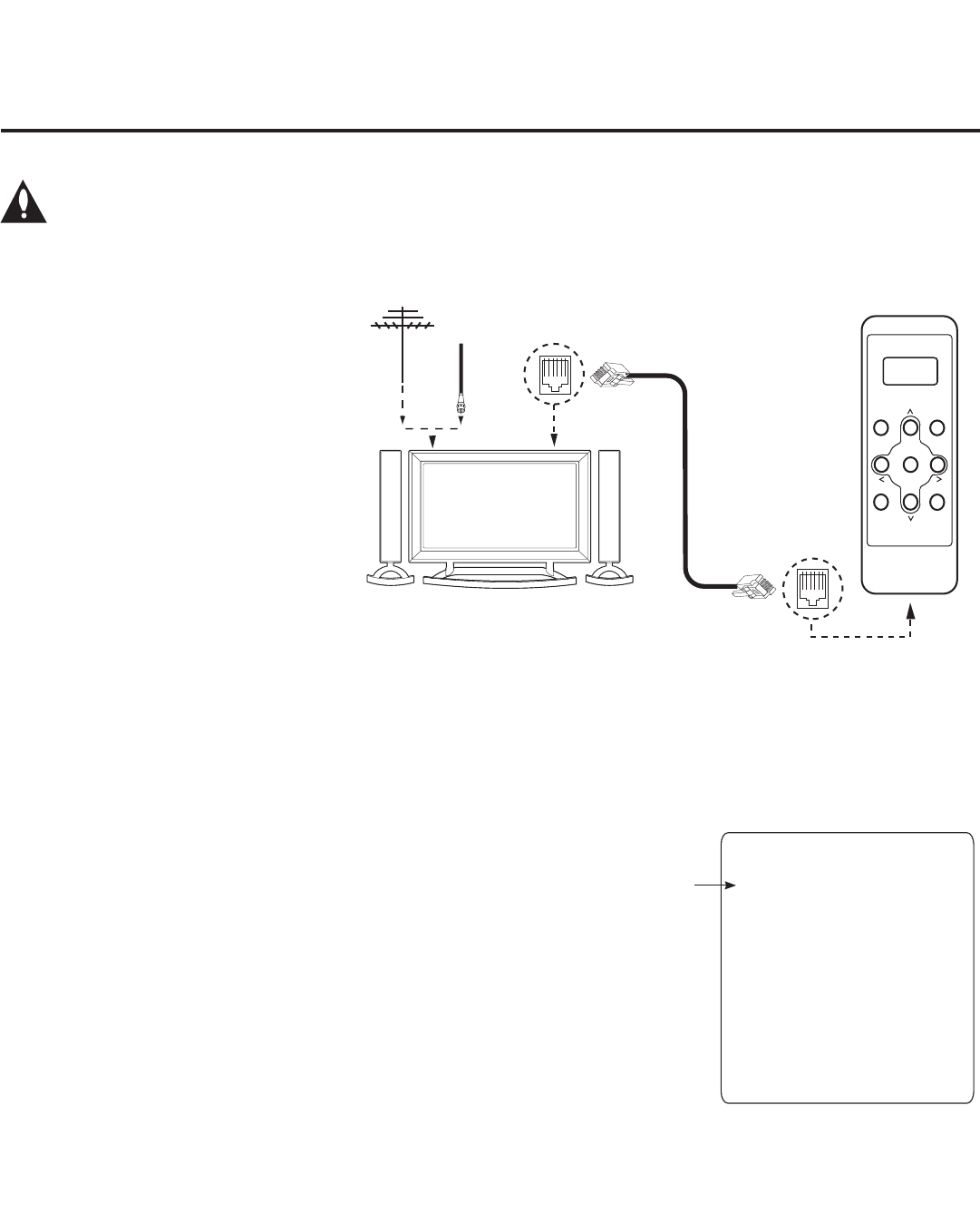
29
206-4200
Clone Programmer Cloning Procedures
Learning / Teaching a Master TV Setup using a TLL-1100A Clone Programmer
Learn Setup from Master TV
1. Ensure the Master TV is set up completely and in Pass-through Mode.
2. Tune/set the TV to an analog channel or Aux input, and then plug one
end of the MPI cable into the TV MPI port.
3. Turn ON the TLL-1100A.
4. Use the MODE button on the TLL-1100A to select Clone Mode.
5. Use the Left/Right arrows on the TLL-1100A to select the Memory CBank
(1 to 8) in which to store the Master TV Setup.
6. Plug the other end of the MPI cable into the MPI port on the bottom of the
TLL-1100A. The Clone Selection Menu will display on the TV screen.
7. Press 1 on the Installer Remote to select LEARN FROM TV from the
Clone Selection Menu. Then, press ENTER to transfer the Master TV
Setup into CBankX on the TLL-1100A.
Learning usually takes about 90 seconds. “LEARNING IN PROGRESS”
will be displayed on the screen while the TLL-1100A copies the Master
Setup. When the Learning process is complete, a “LEARNING COM-
PLETE” message will be displayed.
8. When Learning is complete, disconnect the MPI cable from the Master TV.
Cloning is accomplished using the
TV/clone programmer MPI ports for
communication (see figure).
TLL-1100A Cloning Notes
• Read the IMPORTANT CLONING
INFORMATION on page 24 before
beginning any cloning procedures.
• Ensure the TLL-1100A is either fully
charged or connected to AC power.
• Learning and Teaching is only
possible between identical model
TVs; however, the TLL-1100A can
store up to eight different Master
TV Setups.
Caution: Do not connect a clone programmer to a PPV card installed in the Master or Target
TVs. Also, if the TV is in LodgeNet PPV Mode (check with the site administrator if you are
not certain), do not connect a clone programmer to the GAME CONTROL/MPI port. Either of
these actions will damage the clone programmer and, if applicable, the PPV card.
Antenna
or CATV
CLONE SELECTION MENU
Selected Bank: CBankX Saved
(1) LEARN FROM TV
(2) TEACH TO TV
(3) SET CLONE CLOCK FROM TV
(4) SET TV CLOCK FROM CLONE
(5) DISPLAY TV SETUP
(6) DISPLAY CLONE SETUP
TV Link
Loader
TLL1100A
Ready
TLL-1100A
ENTER
RECEIVE SEND
MENU
MODE
CHARGE
MPI
Cable
TLL-1100A Clone
Programmer
CLONE SELECTION MENU
Selected Bank: CBankX Saved
(1) LEARN FROM TV
(2) TEACH TO TV
(3) SET CLONE CLOCK FROM TV
(4) SET TV CLOCK FROM CLONE
(5) DISPLAY TV SETUP
(6) DISPLAY CLONE SETUP
CLONE CLOCK = XX:XX
TV CLOCK = XX:XX
THE CLONE IS VERSION VX.X.X
-
-
To change menu items, press
channel keys or digits.
To execute item, press Enter.
30 206-4200
Clone Programmer Cloning Procedures (Cont.)
Learning / Teaching a Master TV Setup using a TLL-1100A Clone Programmer (Cont.)
(Optional) Set the Clock
Set the time on a Master TV’s clock. (If the time has already been copied
from a TV into the TLL-1100A clone programmer, you can set the Master
TV’s clock by copying the time from the clone programmer.) The TLL-1100A
can copy the current time to both a Master TV and to the clone’s internal
clock—accurate to within one minute.
Since the TLL-1100A’s time cannot be set directly, the current time needs
to be copied from an LG TV equipped with an enabled MPI port.
After the time is copied to the TLL-1100A clone programmer, the current
time will be maintained and can then be transferred to another TV. (This
can be a Master TV or another TV which has already had the features set
up.)
Teach Master TV Setup to Target TV
1. Ensure the Target TV is in Pass-through Mode, and then use the Installer
Remote to enter the Target TV Installer Menu: Press MENU repeatedly
until the on-screen display of the TV setup menus no longer toggles, and
then press 9-8-7-6 + ENTER.
2. Set Installer Menu item 117 FACT DEFAULT to 001, and press ENTER.
When the value changes back to 0, press ENTER again to exit the
Installer Menu.
3. Tune/set the TV to an analog channel or Aux input (ideally the same
source tuned for 2-5-5 + MENU Mode during the Master TV Setup
procedure), and then connect the MPI cable to the MPI port on the Target
TV. The Clone Selection Menu will display on the TV screen.
4. Ensure the correct Memory CBank(X) is selected on the TLL-1100A.
5. Press 2 on the Installer Remote to select TEACH TO TV from the Clone
Selection Menu. Then, press ENTER to transfer the Master TV Setup to
the Target TV.
Teaching usually takes 3 to 4 minutes. “TEACHING IN PROGRESS” will
be displayed on the screen during Teaching. When the Teaching process
is complete, a “TEACHING COMPLETE” message will be displayed.
6. When Teaching is done, disconnect the MPI cable from the Target TV,
turn OFF the TV, and unplug the TV power cord for 15 seconds.
7. Reconnect the TV power cord, and turn ON the TV. The Master TV
Setup should be resident on the Target TV.
CLONE SELECTION MENU
Selected Bank: CBankX Saved
(1) LEARN FROM TV
(2) TEACH TO TV
(3) SET CLONE CLOCK FROM TV
(4) SET TV CLOCK FROM CLONE
(5) DISPLAY TV SETUP
(6) DISPLAY CLONE SETUP
CLONE CLOCK = XX:XX
TV CLOCK = XX:XX
THE CLONE IS VERSION VX.X.X
-
-
To change menu items, press
channel keys or digits.
To execute item, press Enter.
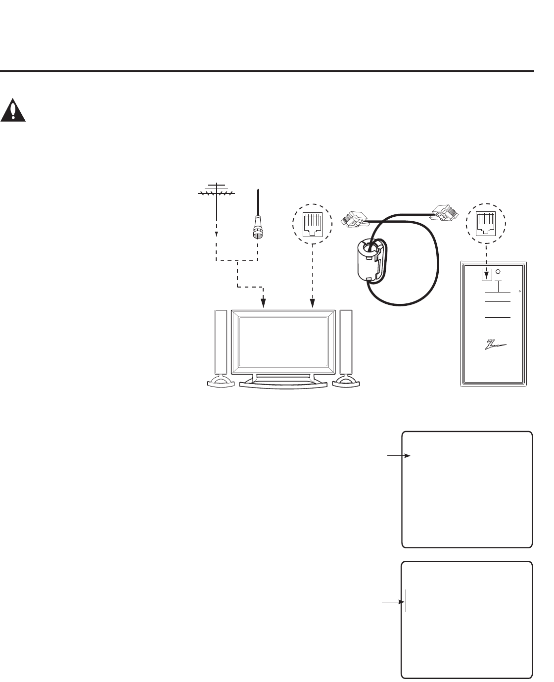
31
206-4200
Clone Programmer Cloning Procedures (Cont.)
Learning / Teaching a Master TV Setup using an LT2002 Clone Programmer
Learn Setup from Master TV
1. Ensure the Master TV is set up completely and in Pass-through Mode.
2. Tune/set the TV to an analog channel or Aux input, and then plug one end
of the MPI cable into the TV MPI port.
3. If there is a good connection after the LT2002 is connected to the TV MPI
port, “THE CLONE HAS CONTROL OF THE TV” message will appear
on the TV screen. Press any key on the Installer Remote to access the
LT2002 Clone Selection Menu.
4. Press 1 on the Installer Remote to select LEARN FROM TV from the
Clone Selection Menu; then press ENTER to proceed to the Memory Bank
Selection Menu.
5. Press 1, 2, or 3 on the Installer Remote to select the clone Memory Bank
in which to store the Master Setup. Then, press ENTER.
Note: If you choose a Memory Bank that already has a Master device’s
setup programmed into it, that setup will be overwritten by the new Master
TV Setup.
6. Verify the Learning setup information on the next screen, and then press
POWER to transfer the Master TV Setup into the selected Memory Bank
on the LT2002.
LT2002 Cloning Notes
• Read the IMPORTANT CLONING
INFORMATION on page 24 before
beginning any cloning procedures.
• A slow ashing green light indicates
that there are communication
problems between the TV and the
LT2002. If this is the case, check for
a damaged cable, poor contacts, or
other connection troubles.
• If the status indicator is red, the
LT2002 batteries are low and should
be replaced. Install four (4) high-
quality alkaline AA batteries.
• Learning and Teaching is only
possible between identical model TVs;
however, the LT2002 can store up to
three different Master TV Setups.
Caution: Do not connect a clone programmer to a PPV card installed in the Master or Target
TVs. Also, if the TV is in LodgeNet PPV Mode (check with the site administrator if you are
not certain), do not connect a clone programmer to the GAME CONTROL/MPI port. Either of
these actions will damage the clone programmer and, if applicable, the PPV card.
Ferrite Core
(TDK, ZCAT
2035-0930)
Antenna
or CATV
QuickSet II Programmer
LT2002
®
ZENITH ELECTRONICS CORPORATION, LINCOLNSHIRE, ILLINOIS, USA
• heartbeat power on
communications ok
• slow power on
no communications
• green battery ok
• red battery low
Blink pattern
Color Reset
Status
Indicator
Connect cable to
TV MPI Jack and
follow on screen
instructions
MPI
THE CLONE HAS CONTROL OF THE TV
THE CLONE IS VERSION XX
THE TV IS VERSION XX
THE SW IS REVISION XX
CLONE CLOCK = XX:XX
TV CLOCK = XX:XX
- PRESS ANY KEY TO CONTINUE.
- DISCONNECT CLONE WHEN DONE.
MPI
Cable
LT2002 Clone
Programmer
(Continued on next page)
SAVE TV SETUP IN SELECTED
CLONE MEMORY
(1) MEMORY 1 VER XX REV XX
(2) MEMORY 2 VER XX REV XX
(3) MEMORY 3 VER XX REV XX
(4) RETURN TO CLONE MENU
-
-
TO CHANGE MENU ITEMS, PRESS
CHANNEL KEYS OR DIGITS.
TO EXECUTE ITEM, PRESS ON/OFF,
POWER, OR ENTER.
COPY SELECTED CLONE MEMORY
TO TV
(1) MEMORY 1 VER XX REV XX
(2) MEMORY 2 VER XX REV XX
(3) MEMORY 3 VER XX REV XX
(4) RETURN TO CLONE MENU
-
-
TO CHANGE MENU ITEMS, PRESS
CHANNEL KEYS OR DIGITS.
TO EXECUTE ITEM, PRESS ON/OFF,
POWER, OR ENTER.
Cloning is accomplished using the TV/clone programmer MPI ports for communication (see figure).
CLONE SELECTION MENU
(1) LEARN FROM TV
(2) TEACH TO TV
(3) SET CLONE CLOCK FROM TV
(4) SET TV CLOCK FROM CLONE
(5) DISPLAY TV SETUP
(6) DISPLAY CLONE SETUP
-
-
TO CHANGE MENU ITEMS, PRESS
CHANNEL KEYS OR DIGITS.
TO EXECUTE ITEM, PRESS ON/OFF,
POWER, OR ENTER.
32 206-4200
Clone Programmer Cloning Procedures (Cont.)
Learning / Teaching a Master TV Setup using an LT2002 Clone Programmer (Cont.)
(Continued from previous page)
Learning usually takes about 90 seconds. “LEARNING IN PROGRESS”
will be displayed on the screen while the LT2002 copies the Master Setup.
When the Learning process is complete, a “LEARNING COMPLETE”
message will be displayed.
7. When Learning is complete, disconnect the MPI cable from the Master TV.
(Optional) Set the Clock
Set the time on a Master TV’s clock. (If the time has already been copied from a
TV into the LT2002 clone programmer, you can set the Master TV’s clock by
copying the time from the clone programmer.) The LT2002 can copy the current
time to both a Master TV and to the clone’s internal clock—accurate to within
one minute. (Another reason that the LT2002 should be equipped with fresh,
high-quality alkaline batteries, is for it to keep the time as accurately as possible.)
Since the LT2002’s time cannot be set directly, the current time needs to be
copied from an LG TV equipped with an enabled MPI port.
After the time is copied to the LT2002 clone programmer, the current time will
be maintained and can then be transferred to another TV. (This can be a
Master TV or another TV which has already had the features set up.)
Teach Master TV Setup to Target TV
1. Ensure the Target TV is in Pass-through Mode, and then use the Installer
Remote to enter the Target TV Installer Menu: Press MENU repeatedly until
the on-screen display of the TV setup menus no longer toggles, and then
press 9-8-7-6 + ENTER.
2. Set Installer Menu item 117 FACT DEFAULT to 001, and press ENTER.
When the value changes back to 0, press ENTER again to exit the Installer
Menu.
3. Tune/set the TV to an analog channel or Aux input (ideally the same source
tuned for 2-5-5 + MENU Mode during the Master TV Setup procedure), and
then connect the MPI cable to the MPI port on the Target TV.
4. With “THE CLONE HAS CONTROL OF TV” message on display, press 2
on the Installer Remote to select TEACH TO TV from the LT2002 Clone
Selection Menu. Then, press ENTER.
5. Select the LT2002 Memory Bank in which the new Master TV Setup is
located, and press ENTER.
6. Verify the Teaching setup information on the next screen, and then press
POWER to transfer the Master TV Setup to the Target TV.
Teaching usually takes 3 to 4 minutes. “TEACHING IN PROGRESS” will
be displayed on-screen during Teaching. When the Teaching process is
complete, a “TEACHING COMPLETE” message will be displayed.
7. When Teaching is done, disconnect the MPI cable from the Target TV, turn
OFF the TV, and unplug the TV power cord for 15 seconds.
8. Reconnect the TV power cord, and turn ON the TV. The Master TV Setup
should be resident on the Target TV.
CLONE SELECTION MENU
(1) LEARN FROM TV
(2) TEACH TO TV
(3) SET CLONE CLOCK FROM TV
(4) SET TV CLOCK FROM CLONE
(5) DISPLAY TV SETUP
(6) DISPLAY CLONE SETUP
-
-
TO CHANGE MENU ITEMS, PRESS
CHANNEL KEYS OR DIGITS.
TO EXECUTE ITEM, PRESS ON/OFF,
POWER, OR ENTER.
CLONE SELECTION MENU
(1) LEARN FROM TV
(2) TEACH TO TV
(3) SET CLONE CLOCK FROM TV
(4) SET TV CLOCK FROM CLONE
(5) DISPLAY TV SETUP
(6) DISPLAY CLONE SETUP
-
-
TO CHANGE MENU ITEMS, PRESS
CHANNEL KEYS OR DIGITS.
TO EXECUTE ITEM, PRESS ON/OFF,
POWER, OR ENTER.
SAVE TV SETUP IN SELECTED
CLONE MEMORY
(1) MEMORY 1 VER XX REV XX
(2) MEMORY 2 VER XX REV XX
(3) MEMORY 3 VER XX REV XX
(4) RETURN TO CLONE MENU
-
-
TO CHANGE MENU ITEMS, PRESS
CHANNEL KEYS OR DIGITS.
TO EXECUTE ITEM, PRESS ON/OFF,
POWER, OR ENTER.
COPY SELECTED CLONE MEMORY
TO TV
(1) MEMORY 1 VER XX REV XX
(2) MEMORY 2 VER XX REV XX
(3) MEMORY 3 VER XX REV XX
(4) RETURN TO CLONE MENU
-
-
TO CHANGE MENU ITEMS, PRESS
CHANNEL KEYS OR DIGITS.
TO EXECUTE ITEM, PRESS ON/OFF,
POWER, OR ENTER.

33
206-4200
Caution: (FTG Mode via CPU only) If applicable, IP/network settings must be completed in
the IP Environment Menu before a TV is congured for FTG Mode (see page 45 for further
information—the default network setting is DHCP). If IP/network requirements change after
a TV has been congured for FTG Mode, the TV will need to be reset to Pass-through Mode
before the settings can be modied (see Reference section, “Resetting Factory Defaults on
the TV(s),” for further information).
FTG Mode via CPU
This mode provides the following features:
• Logical channels mapped to either RF or IP delivered
content.
• Digital RF channel minor (program) numbers up to 999.
• FTG Channel Map of up to 600 logical channels.
• Start Channel set for RF, Aux input, or IP delivered content.
• Pro:Centric data delivery over RF or IP.
FTG Mode via CPU requires LG FTG File Manager PC
software to create an FTG Conguration (.tlx) le. In this
mode, the CPU is the owner of the FTG Channel Map and
must be congured with an FTG Channel Map and FTG
Installer Menu settings using one of the following processes:
• Local: Congure an individual LD660H/LD665H/LV555H
TV via its USB port using an FTG Conguration (.tlx)
le on a USB memory device. The “Teach to TV (TLX)”
process, along with associated procedures, is described
on pages 35 to 39.
• Remote: Congure all LD660H/LD665H/LV555H TVs at
the site using a Pro:Centric server head end device
(Example: PCS150R). Load an FTG Conguration (.tlx)
le on the Pro:Centric server using the TV E-Z Installation
“Conguration” option in the Pro:Centric Server Admin
Client. Refer to the Pro:Centric™ Server Admin Client
User Guide for further information.
FTG Mode via EBL
This mode provides the following features:
• Logical channels mapped to RF delivered content.
• Digital RF channel minor (program) numbers up to 255.
• FTG Channel Map of up to 141 logical channels.
• Start Channel set for RF or Aux input delivered content.
• Pro:Centric data delivery over RF.
FTG Mode via EBL requires LG FTG Device Conguration
Application PC software to create an FMA Conguration
(.fma) le. In this mode, the EBL is the owner of the FTG
Channel Map and must be congured with an FTG Chan-
nel Map and FTG Installer Menu settings using one of the
following processes:
• Local: Congure an individual LD660H/LD665H/LV555H
TV’s EBL via its TV-LINK CFG jack using a direct PC-to-
TV connection and the FTG Device Conguration Appli-
cation. The “Write” process for an FTG Channel Map and
FTG Installer Menu settings is described on page 40.
• Remote: Congure all LD660H/LD665H/LV555H TV EBLs
at the site using a Free-To-Guest Management Appliance
(FMA) head end device (Example: FMA-LG101). Refer
to the Free-To-Guest (FTG) Configuration Application
manual and/or the Installation & Setup manual for the
FMA device for further information.
FTG Mode of Operation Overview
FTG Mode via CPU or EBL
FTG Mode enables Pro:Idiom decryption and also allows logical channel mapping of physical channels.
As indicated in the introduction to this document, there are two separate and distinct methods for configuring
LD660H/LD665H and LV555H TVs for FTG Mode of operation: one (new) method is to configure the TV
CPU for FTG Mode operation, while the other is to configure the TV EBL for FTG Mode operation. FROM A
LOCAL CONFIGURATION STANDPOINT, EACH OF THESE METHODS IS MUTUALLY EXCLUSIVE. IF
THE CPU IS IN FTG MODE, THE EBL CANNOT BE SWITCHED TO FTG MODE. LIKEWISE, IF THE EBL
IS IN FTG MODE, THE CPU CANNOT BE SWITCHED TO FTG MODE.
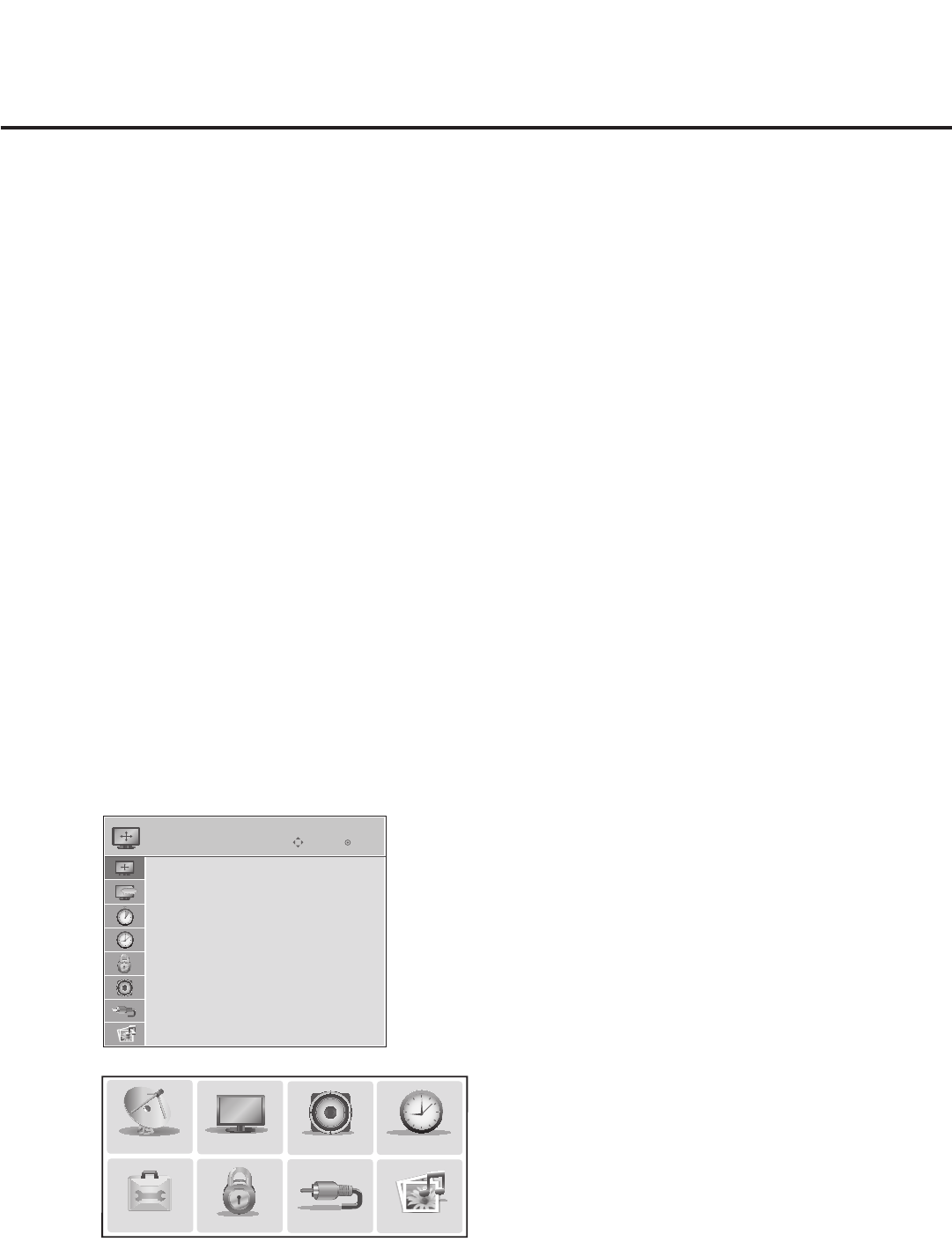
34 206-4200
FTG Mode of Operation Overview (Cont.)
PICTURE AUDIO
INPUT
OPTION
TIME
USB
CHANNEL
LOCK
TV Setup Menus
Shows that the TV is in
Pass-through Mode .
Function Menu
Indicates the TV (CPU or EBL) is not
in Pass-through Mode . While the TV is
in FTG Mode, Installer Menu settings
can be accessed as read-only.
ABC
ASPECT RATIO
Enter
Move
Set By Program
4:3
16:9
Zoom
Just Scan
While the TV is in FTG Mode:
• Users can still access the Installer Menu using an LG Installer Remote; however, all Installer Menu
items will be read-only.
• Any FTG conguration changes must be made using either the FTG File Manager (FTG Mode via CPU)
or the FTG Device Conguration Application (FTG Mode via EBL). FTG Channel Map Conguration and
FTG Installer Menu Conguration Utilities enable you to make changes, respectively, to the FTG Channel
Map and FTG Installer Menu settings as necessary. Based on the initial method used to congure the TV
for FTG Mode operation (via CPU or EBL), all subsequent changes must be transferred to either the TV
or the EBL via a process that is in accordance or compatible with that method (see information on local
conguration in this document or refer to documentation for the head end device/server for information on
remote management).
• If it becomes necessary to reset the TV to Pass-through Mode, there are several options that will enable
you to do so. Refer to Reference section, “Resetting Factory Defaults on the TV(s),” for further information.
Pages 41 to 44 provide overviews of the utilities that comprise the FTG File Manager. Refer to the Free-
To-Guest (FTG) File Manager User Guide for further information on the FTG File Manager. Refer to the
Free-To-Guest (FTG) Configuration Application manual for information on the FTG Device
Configuration Application.
Determining the TV Operating Mode
To determine the operating mode of the TV, press MENU on the Installer Remote. The menu display
alternates based on the operating mode. See examples below.
If the end user Function Menu appears, typically the TV is in FTG Mode. If the TV setup menus appear,
the TV is in Pass-through Mode.
Note: If the TV is not in FTG Mode, but both the Data Channel and the Pro:Centric Application Mode
have been set in the Installer Menu or the Pro:Centric Menu, the TV is in Application Tuning Mode. In
Application Tuning Mode, only the Function Menu is available to end users instead of the TV setup
menus; however, Installer Menu items remain editable (not read-only).

35
206-4200
FTG Mode via CPU
Creating an FTG Conguration File using the FTG File Manager
This section describes how to create an FTG Conguration (.tlx) le that can be saved to a USB memory
device. In order to enable Pro:Idiom decryption, it is recommended that you create an FTG Conguration
le using the FTG File Manager.
Notes: • FTG File Manager software is available online at: www.LGcommercial.com/FTGsoftware.
• There is also an option to save (Learn) an FTG Conguration le from a TV, which may be
desirable or required in either of the following situations:
− If you want to save customized TV setup menu settings to the FTG Conguration le (in
addition to the FTG Channel Map and FTG Installer Menu settings).
− If you do not know the RF channels at the site.
See “
Learning an FTG Conguration File from a TV” on
page 38 for further information. How-
ever, if you use this option to save an FTG Conguration le, it is still highly recommended
that you open the new FTG Conguration le in the FTG File Manager to verify the le
contents/settings and to enable Pro:Idiom decryption by marking Encrypted channels.
The procedure below provides an overview of the steps required to create an FTG Configuration (.tlx)
file. Refer to the Free-To-Guest (FTG) File Manager User Guide for further information. See also FTG
File Manager sample screens on pages 41 to 44.
1. Install (if necessary) and launch the FTG File Manager (v1.0.0 or higher) on the PC that will be used
to create the FTG Configuration (.tlx) file.
2. You have a number of options:
• To view and/or base a new FTG Conguration le on an existing LD660H/LD665H or LV555H FTG
Conguration (.tlx) le, click Open under the TLX File section of the FTG File Manager main screen,
and select the desired (.tlx) file.
A list of the file’s contents will be displayed in the TLX File Contents window. Double-click each item
individually or click Copy All to transfer all the items listed to the FTG Configuration List and, if
applicable, to the TV Setup Menu List, though note that while TV setup menu settings can be included
in the new FTG Configuration file, the TV Setup Menu List is not available for editing.
Edit the configuration of the items in the FTG Configuration List as well as the FTG Configuration
List, as necessary, to create a new file, and then proceed to step 4 when you are ready to continue.
• If applicable, you can also open an existing FTG Conguration (.rml) le created in the FTG Device
Conguration Application to use its FTG Channel Map and/or FTG Installer Menu settings. Edit the
channels and/or settings as necessary.
• Otherwise, create a new FTG Channel Map using the FTG Channel Map Editor in the FTG Channel
Map Conguration Utility. Then, continue with step 3.
Note: Up to 600 logical channels (combined total of both RF and IP mapped channels) can be
defined in the FTG Channel Map.
3. If necessary, click Configure in the FTG File Manager menu bar, and select FTG File Manager to
return to the FTG File Manager main screen.
(Continued on next page)

36 206-4200
FTG Mode via CPU (Cont.)
(Continued from previous page)
4. To add an FTG Channel Map, click >> under FTG Channel Map to copy the current Mapped RF
Channels and Mapped IP Channels to the FTG Configuration List.
Note: If you make any change(s) in the FTG Channel Map Configuration Utility to the current data to
be included in the FTG Configuration List, you will need to recopy the FTG Channel Map to the FTG
Configuration List.
5. (Optional) Load default FTG Installer Menu settings for the TV:
• Click the down arrow at the right of the Chassis eld under Installer Menu Templates, and select the
appropriate option (depending on the TV type) from the drop-down list of available models.
• Click the Load button.
• Use the FTG Installer Menu Conguration Utility to modify settings, if necessary. Then, return to the
FTG File Manager main screen.
6. To add FTG Installer Menu settings, click >> under FTG Installer Menu Settings to copy the current set-
tings to the FTG Conguration List.
Note: If you make any change(s) in the FTG Installer Menu Configuration Utility to the current data to
be included in the FTG Configuration List, you will need to recopy the FTG Installer Menu settings to
the FTG Configuration List.
7. Click the Save button above the FTG Configuration List to save its contents (including TV setup menu
settings, if present) to an FTG Configuration (.tlx) file on the PC’s hard drive for later use (default
folder path is C:\Program Files\Zenith\FTG\TLX).
8. Transfer the FTG Configuration file to a USB memory device, and proceed to “Teaching FTG
Configuration to a TV” below to transfer the FTG Configuration file to an LD660H/LD665H or LV555H TV.
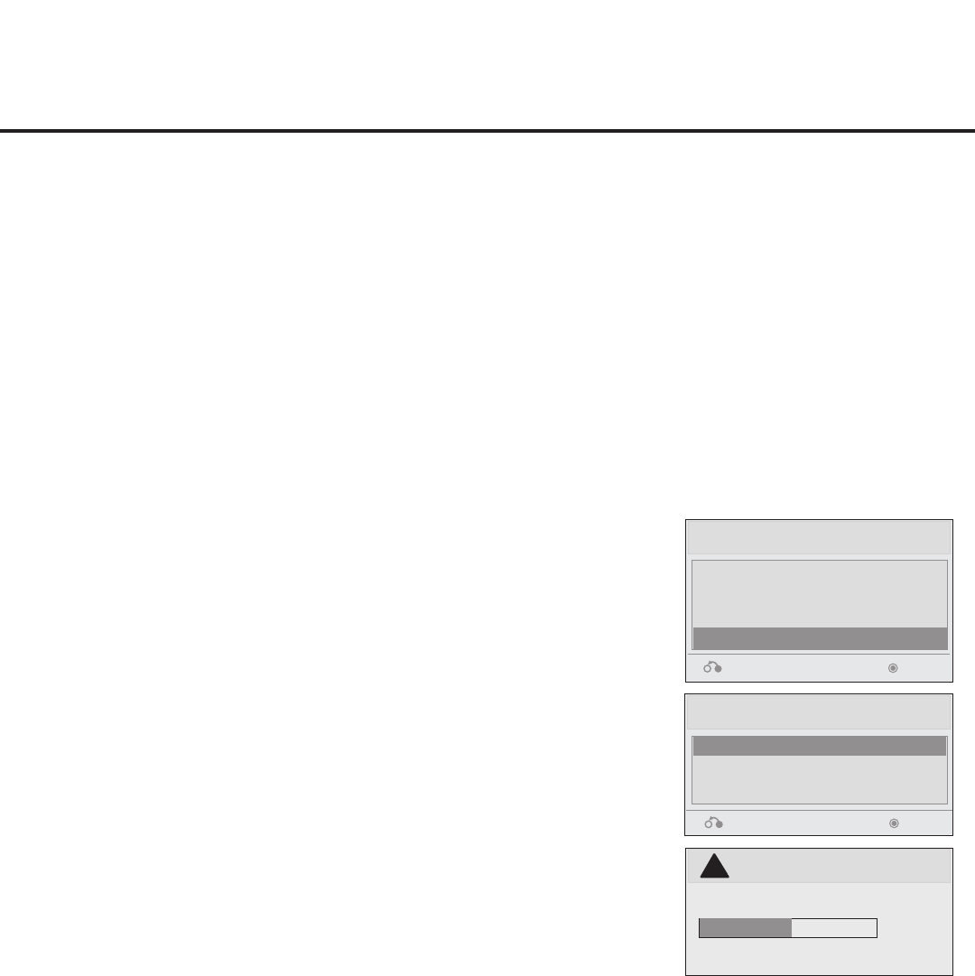
37
206-4200
1. Plug the USB memory device that contains the FTG Conguration
le into the Target LD660H/LD665H or LV555H TV USB IN port.
2. Press MENU on the Installer Remote to display the TV setup
menus (TV is in Pass-through Mode) or the Function Menu (TV is
already in FTG Mode).
3. Use the arrow navigation keys to select/highlight either the Option
menu icon from the TV setup menus or the Lock menu icon from
the Function Menu. Then, press the number “7” key a total of seven
times to display the USB Download Menu.
4. Use the Up/Down arrow keys to select Teach To TV (TLX), and then
press ENTER.
5. Use the Up/Down arrow keys to select the FTG Conguration le
you want to install, and then press ENTER.
The TV will show Teaching completion progress in a new window.
Do NOT remove the USB device until Teaching is complete. When
Teaching is complete, the TV will tune to the rst logical channel in
the FTG Channel Map.
6. When Teaching is done, remove the USB memory device. The
FTG Configuration should be resident on the Target TV. Also, the
Target TV CPU is now in FTG Mode (if it was previously in Pass-
through Mode).
Teach To TV (TLX)
xxLD660H-UA00005.TLX
Return Enter
USB Download Menu
Upgrade TV Software
Upgrade PTC Software
Teach To TV (TLL)
Teach To TV (TLX)
Return Enter
Teach To TV
UPDATING...
Do not unplug!
!
50%
Teaching FTG Conguration to a TV
This procedure describes how to “Teach” an FTG Conguration le from a USB memory device to a TV.
Ensure you have completed the procedure on the previous page to create the FTG Conguration le
before proceeding with the steps below.
Notes: • If the TV is not in FTG Mode, but both Pro:Centric items (098 PRO:CENTRIC and 119 DATA
CHANNEL) have already been set in the Installer Menu on a TV, Teach to TV options will not
be available from the USB Download Menu.
• If the TV EBL is already in FTG Mode, you cannot use this procedure to make changes to
the FTG Channel Map and FTG Installer Menu settings. You must use a direct PC-to-TV
connection as described on page 40 or an FMA head end device to recongure the EBL.
• If either of the preceding conditions applies, but you wish to switch the TV to FTG mode via
CPU, refer to Reference section, “Resetting Factory Defaults on the TV(s),” for further
information before proceeding.
FTG Mode via CPU (Cont.)
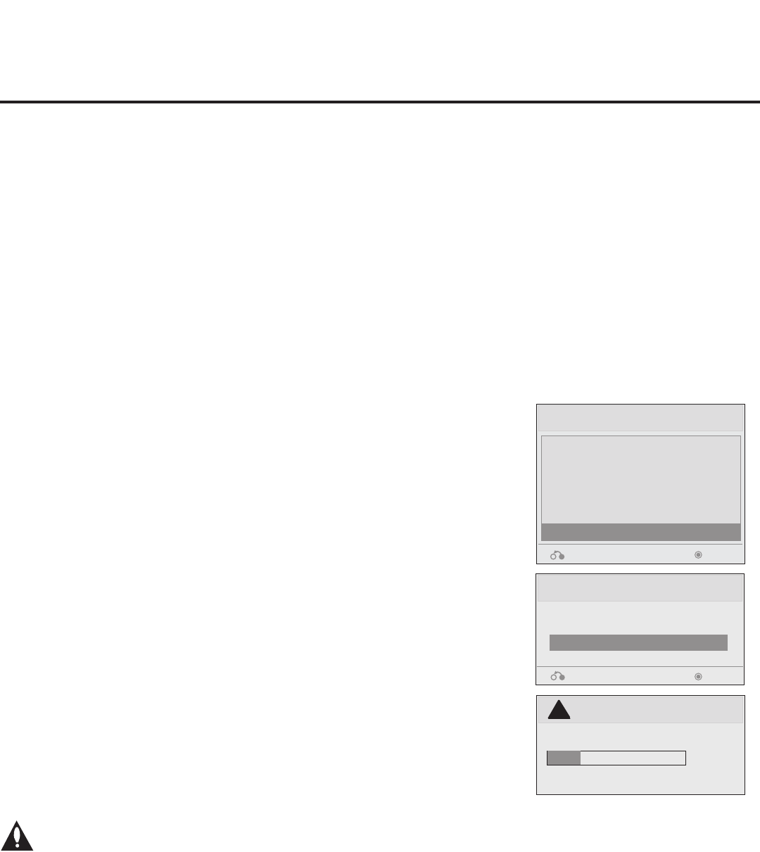
38 206-4200
1. Plug a USB memory device into the USB IN port on the TV.
2. Press MENU on the Installer Remote to display the TV setup
menus (TV is in Pass-through Mode) or the Function Menu (TV is
already in FTG Mode).
3. Use the arrow navigation keys to select/highlight either the Option
menu icon from the TV setup menus or the Lock menu icon from
the Function Menu. Then, press the number “7” key a total of seven
times to display the USB Download Menu.
4. To gain access to the Learn From TV options in the USB Down-
load Menu, key in the password used to enter the Installer Menu
(Example: Press 9-8-7-6).
5. Use the Up/Down arrow keys to select Learn From TV (TLX), and
then press ENTER.
6. To differentiate this .tlx le from others, you can use the Up/Down
arrow keys to change the last ve digits of the lename. Press
ENTER when you are ready to initiate Learning.
The TV will show Learning completion progress in a new window.
Do NOT remove the USB device until Learning is complete. When
Learning is complete, the USB Download Menu will reappear on
screen.
7. When you are nished, remove the USB memory device.
Learn From TV (TLX)
Select the le name and press OK to start
xxLD660H-UA00005.TLX -
Return
Enter
►
►
USB Download Menu
Upgrade TV Software
Upgrade PTC Software
Teach To TV (TLL)
Teach To TV (TLX)
Learn From TV (TLL)
Learn From TV (TLX)
Return Enter
Learn From TV
UPDATING...
Do not unplug!
!25%
Note: It is highly recommended that you open this FTG
Configuration file in the FTG File Manager—BEFORE transferring
(Teaching) the file to any TVs—to verify FTG Channel Map and
FTG Installer Menu settings and enable Pro:Idiom decryption by
marking Encrypted channels. This will also enable you to confirm
and add channel attributes, labels, etc.
Learning an FTG Conguration File from a TV
To ensure that Pro:Idiom decryption is enabled, it is recommended that you create an FTG Configuration
file using the FTG File Manager as described on pages 35 to 36. However, if necessary, this option
enables you to save (Learn) an FTG Configuration file from an LD660H/LD665H or LV555H TV to a USB
memory device.
Notes: • The option to save (Learn) an FTG Conguration le from a TV may be desirable or required
in either of the following situations:
− If you want to save customized TV setup menu settings to the FTG Conguration le
(in addition to the FTG Channel Map and FTG Installer Menu settings).
− If you do not know the RF channels at the site.
• If the TV is NOT already in FTG Mode, you may need to perform some manual conguration
on the TV before you start this procedure (see “Optional Manual Conguration / TV Setup”
on following page).
FTG Mode via CPU (Cont.)

39
206-4200
FTG Mode via CPU (Cont.)
Typical Installer Menu
Note: The Installer Menu header will vary
depending on the TV you are setting up.
Use Channel Menu options to run
Auto Tuning and edit the channel
lineup, as necessary.
Adjust the settings for these
Installer Menu items.
117 FACT DEFAULT 001
003 BAND/AFC 00X
Set Installer Menu Items
These steps provide specic instruction only on the Installer Menu items
that should be set on an LD660H/LD665H or LV555H TV. Refer to pages
15 to 22 for detailed information on all Installer Menu items.
1. Make sure the TV is ON. Then, use the Installer Remote to enter the
Installer Menu: Press MENU repeatedly until the on-screen display of the
TV setup menus no longer toggles, and then press 9-8-7-6 + ENTER.
2. Set Installer Menu item 117 FACT DEFAULT to 001 and press ENTER
on the Installer Remote.
This clears all Installer Menu custom settings, the channel lineup, etc.
and reloads the factory default settings. The value will change back to
0 after the commercial controller (PTC) has been restored to factory
default condition. This step ensures that the TV Channel Memory will be
the active channel lineup.
3. Set Installer Menu item 003 BAND/AFC, as appropriate.
• Broadcast: Set to 000. • HRC: Set to 002.
• CATV: Set to 001 (default). • IRC: Set to 003.
4. Set any other Installer Menu items that affect your TV programming
network to the required conguration. For example, enable/disable Aux
inputs, set a Start Channel, etc.
5. After you have adjusted all required Installer Menu item settings, press
ENTER once on the Installer Remote to save your changes; then, press
ENTER again to exit the menu.
Run Auto Tuning (Channel Search)
Note: In the FTG Conguration le, Logical Channel numbers will automati-
cally be assigned in ascending order, starting with 0 (zero), to the Physical
Channels from the TV Channel Map.
Note: Pro:Idiom decryption for encrypted channels will not be enabled unless
you use the FTG File Manager to set the channel attributes.
1. Search for all available analog and digital channels: Use the Installer
Remote to go to the Channel Menu, select the Auto Tuning option, and
follow the on-screen instructions.
2. Use the Channel Edit option in the Channel Menu to edit the channel
lineup, as necessary, to include free to guest channels only. Add/delete
channels per your system requirements.
Optional Manual Conguration / TV Setup
The manual configuration procedures below should only be performed if you do not know the RF channels
at the site and need to “Learn” an FTG Configuration file from an LD660H/LD665H or LV555H TV as
described on the previous page. Ensure the TV is in Pass-through Mode before you begin.
Once you have completed these procedures, return to “Learning an FTG
Conguration File from a TV” on the previous page to complete the Learn
sequence.
xxLD66xH PTC INSTALLER MENU
000 INSTALLER SEQ 000
UPN 000-000-000-000 ASIC D279
PTC V1.00.016 CPU V1.21.00
Enter
Move
CHANNEL
Auto Tuning
Manual Tuning
Channel Edit
Channel Label
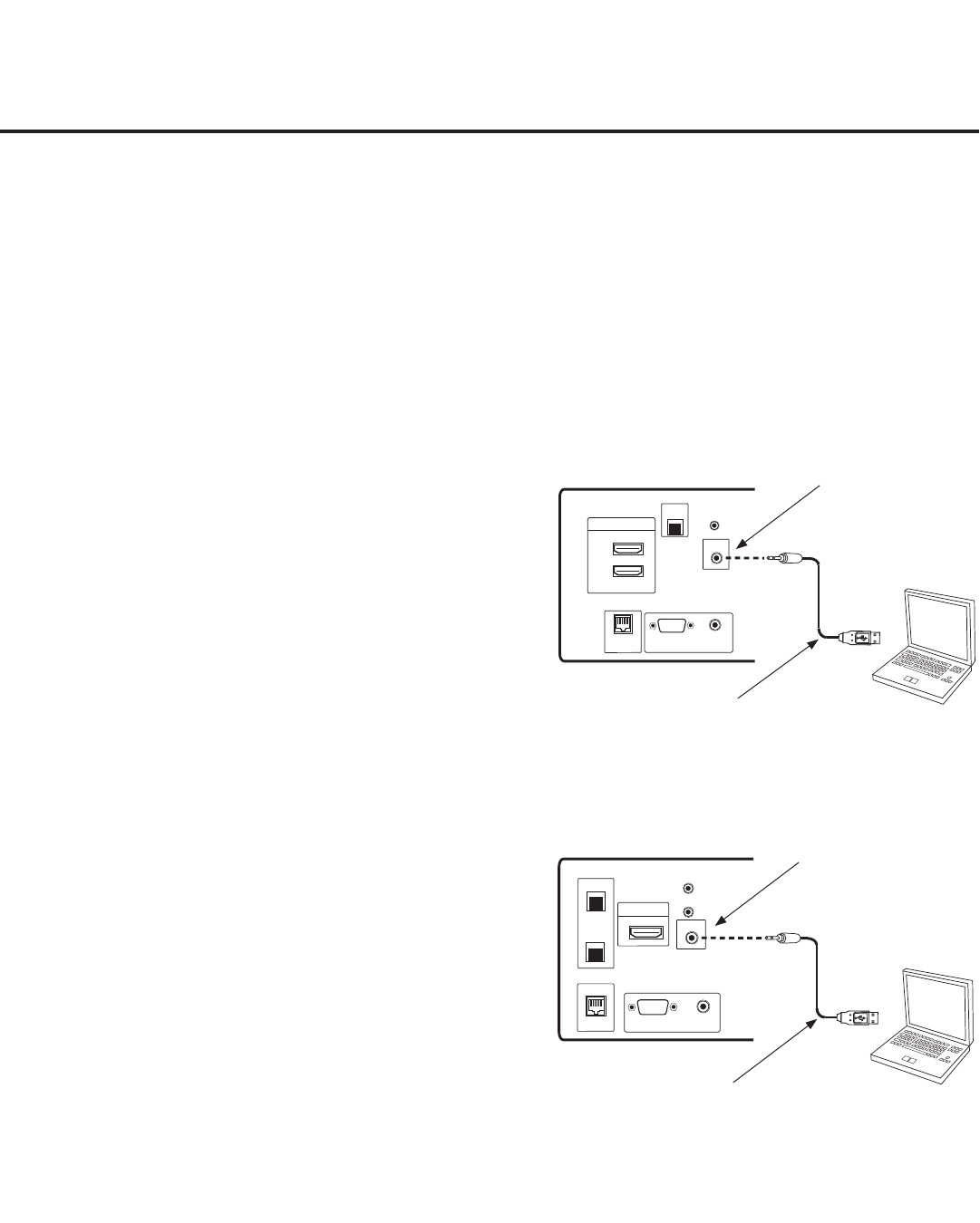
40 206-4200
Laptop
PC
RESET
AUDIO IN
(RGB/DVI)
..........
2
1
HDMI/DVI IN
RJP
INTERFACE
RGB IN (PC)
.....
.....
.....
LAN2
TV-LINK CFG
..........
UPDATE
RESET
AUDIO IN
(RGB/DVI)
1
HDMI/DVI IN
INTERFACE
RGB IN (PC)
.....
.....
.....
LAN2
TV-LINK CFG
..........
LAN1
RJP
Laptop
PC
FTG Mode via EBL (Local Conguration)
LD660H/LD665H
Jack Panel
LV555H
Jack Panel
1. Install (if necessary) and launch the FTG Device
Configuration Application (v5.0.0 or higher) on the
PC that will be used to configure the EBL.
2. Build an FTG Channel Map using the FTG Channel
Map Editor in the FTG Channel Map Configuration
Utility (or, if applicable, open an existing FTG
Configuration [.rml] file).
Note: Up to 141 logical channels can be defined in
the FTG Channel Map.
3. Connect the PC to the TV-LINK CFG jack on the
TV’s rear connections panel using a USB-to-TTL
serial cable (TTL-232R-5V-AJ). If necessary, install
the device driver on the PC.
4. Turn ON the TV.
Note: If Installer Menu item 118 POWER SAVINGS
is set to 3 (default), the TV must be ON in order for
steps 5 and 6 below to be successful.
5. “Write” the FTG Channel Map to the EBL (switches
the EBL from Pass-through Mode to FTG Mode).
Note: After a “Write” of new data, the TV will briefly
display a green text banner that shows the EBL firm-
ware version and release date.
6. “Read” the current FTG Installer Menu settings from
the EBL using the FTG Installer Menu Configuration
Utility. If necessary to make changes to Installer
Menu items, “Write” them back to the EBL in FTG
Mode.
7. Save the FTG Channel Map and FTG Installer Menu
settings to an FTG Configuration (.rml) file for future
use.
8. Tune the TV to a Logical Channel in the FTG
Channel Map.
The following steps outline local FTG configuration of individual TV EBLs using a direct PC-to-TV
connection. Refer to the Free-To-Guest (FTG) Configuration Application manual for further information.
Notes: • FTG Device Conguration Application software is available online at: www.LGcommercial.com/
FTGsoftware.
• If the TV CPU is already in FTG Mode, you cannot use this procedure to make changes to the
FTG Channel Map and FTG Installer Menu settings. Instead, refer to and use the processes
described on pages 35 to 37 to recongure the TV CPU.
• If the preceding condition applies, but you wish to switch the TV to FTG Mode via EBL, refer
to Reference section, “Resetting Factory Defaults on the TV(s),” for further information before
proceeding.
TV-LINK CFG
Use for direct PC-to-
TV FTG configuration.
USB-to-TTL Serial Cable
Required for direct PC-to-TV
FTG configuration.
Laptop
PC
RESET
AUDIO IN
(RGB/DVI)
..........
2
1
HDMI/DVI IN
RJP
INTERFACE
RGB IN (PC)
.....
.....
.....
LAN2
TV-LINK CFG
..........
UPDATE
RESET
AUDIO IN
(RGB/DVI)
1
HDMI/DVI IN
INTERFACE
RGB IN (PC)
.....
.....
.....
LAN2
TV-LINK CFG
..........
LAN1
RJP
Laptop
PC
TV-LINK CFG
Use for direct PC-to-
TV FTG configuration.
USB-to-TTL Serial Cable
Required for direct PC-to-TV
FTG configuration.
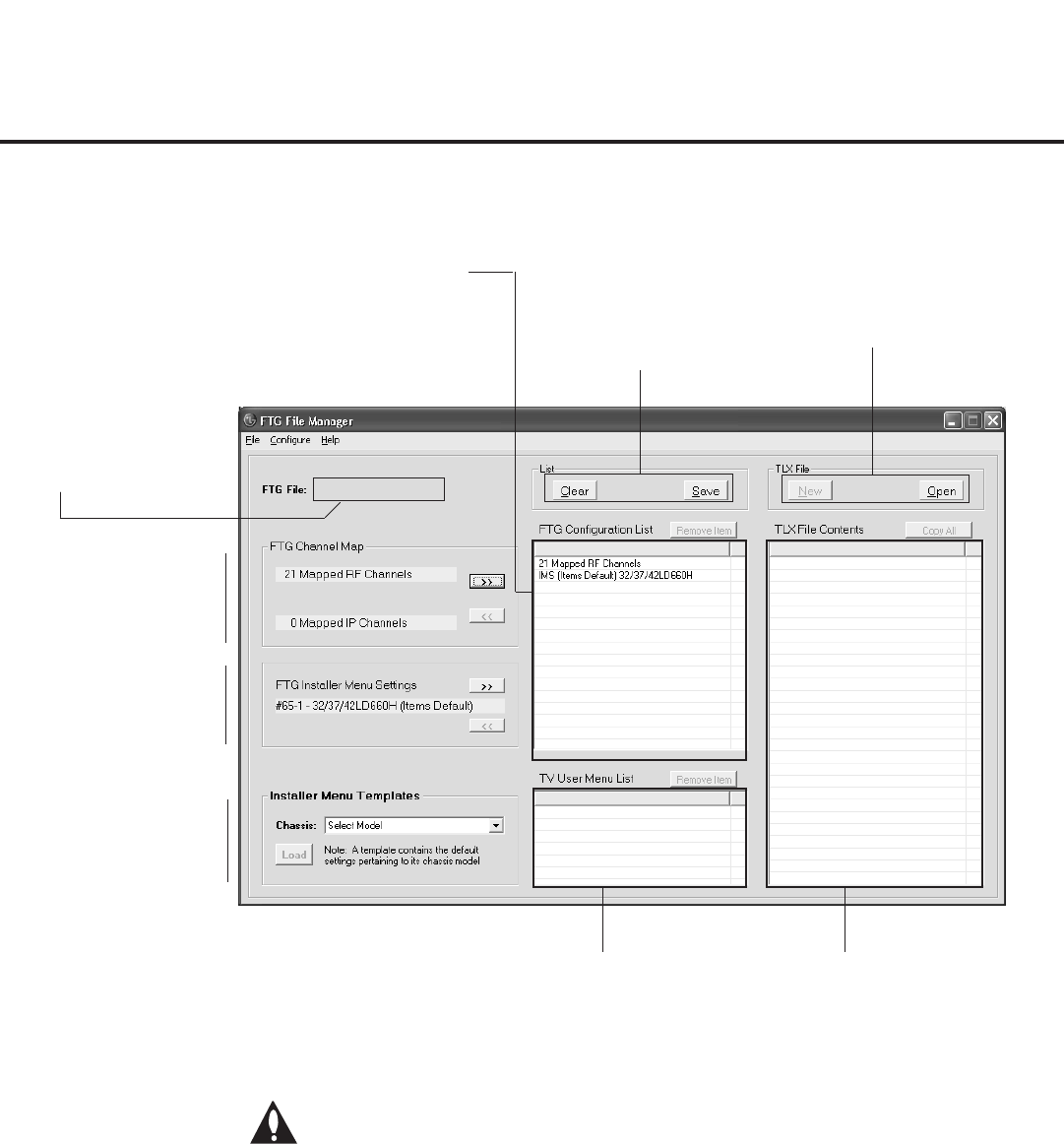
41
206-4200
Note: The data referenced in the FTG Conguration List is only a snap-
shot of the current FTG Channel Map and FTG Installer Menu settings
when copied to the list. If you make any change(s) to the current data
to be included in the FTG Conguration List, you will need to recopy
Channel Map and Installer Menu settings to the FTG Conguration List.
FTG File Manager Utilities Overview
Load default FTG Installer
Menu for LD660H/
LD665H or LV555H.
Copy FTG Installer Menu
settings to and from FTG
Configuration List.
Copy FTG Channel Map
to and from FTG
Configuration List.
Filename of opened FTG
Configuration (.rml) file
created using FTG Device
Configuration Application.
FTG CONFIGURATION LIST
Data to be saved in FTG
Configuration (.tlx) file.
FTG File Manager Main Screen
NEW/OPEN
TLX File options.
CLEAR/SAVE
FTG Configuration
List options.
TV SETUP MENU LIST
Data to be saved in FTG
Configuration file.
TLX FILE CONTENTS
Data contained in opened
FTG Configuration (.tlx) file.
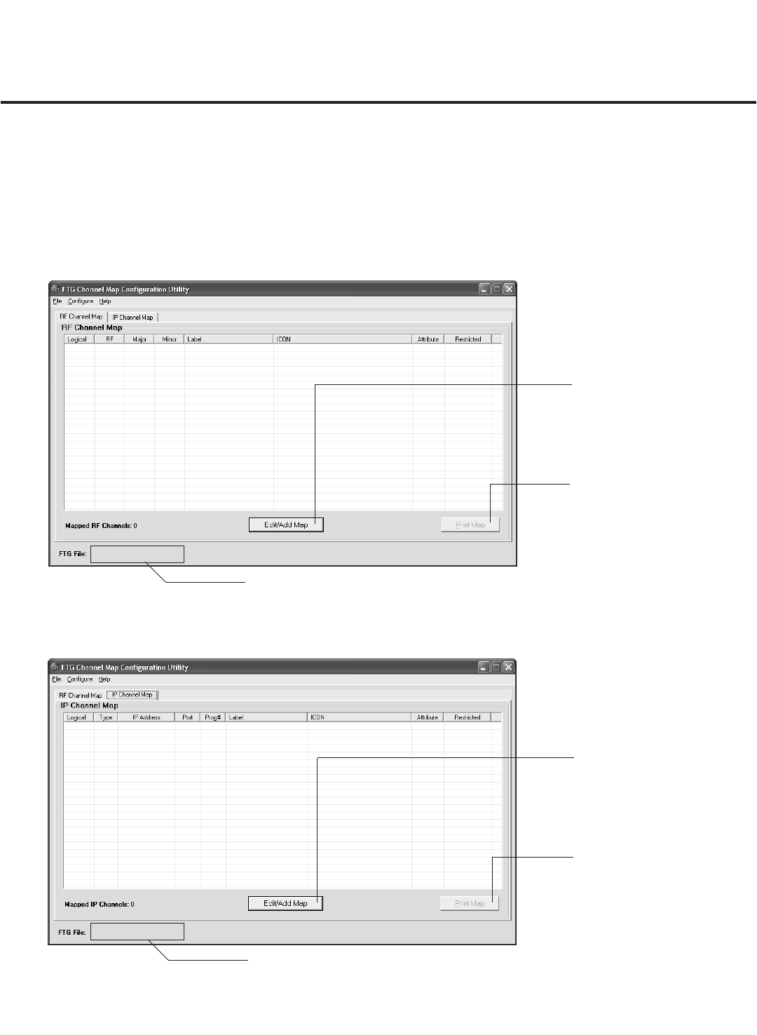
42 206-4200
FTG Channel Map Conguration Utility
The FTG Channel Map Configuration Utility enables you to build a Channel Map with logical channel
numbers. The FTG Channel Map for LD660H/LD665H and LV555H TVs may contain both RF and IP
channels. Select the appropriate tab—RF Channel Map or IP Channel Map—as necessary, either in this
screen, or in the Channel Map Editor (see next page).
PRINT MAP
Click to display a printable
FTG Channel Map Report. The
report can also be exported as
an HTML or Text file.
EDIT/ADD MAP
Click to open the FTG Channel
Map Editor to create or edit an
FTG Channel Map (see next
page).
FTG File Manager Utilities Overview (Cont.)
RF Channel Map
IP Channel Map
PRINT MAP
Click to display a printable
FTG Channel Map Report. The
report can also be exported as
an HTML or Text file.
EDIT/ADD MAP
Click to open the FTG Channel
Map Editor to create or edit an
FTG Channel Map (see next
page).
Filename of opened FTG Configuration
(.rml) file created using FTG Device
Configuration Application.
Filename of opened FTG Configuration
(.rml) file created using FTG Device
Configuration Application.
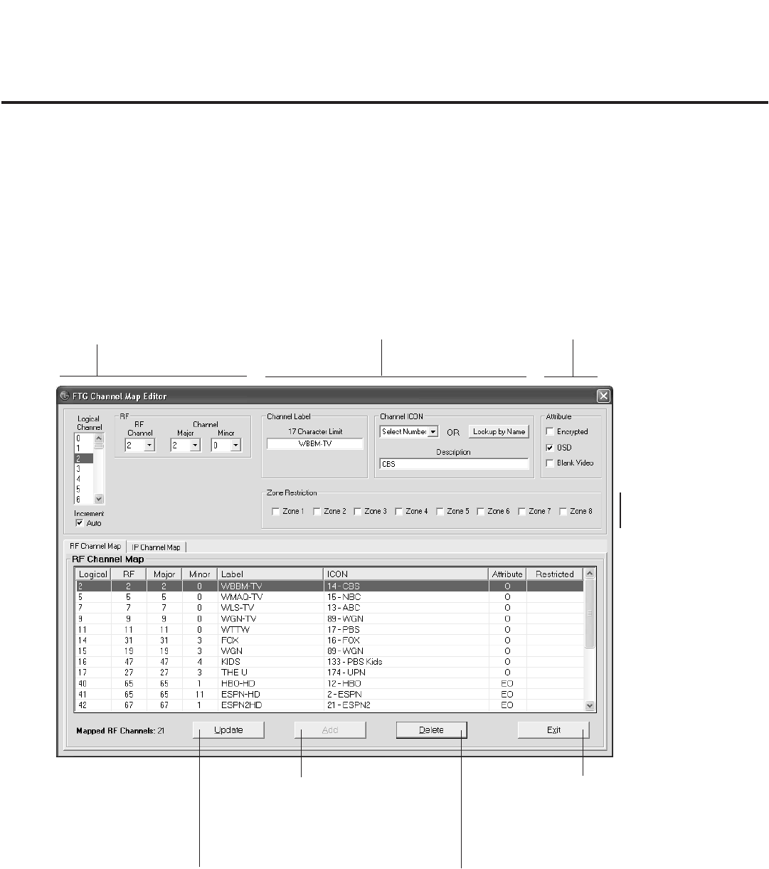
43
206-4200
FTG File Manager Utilities Overview (Cont.)
DELETE
Click to remove highlighted
channel from FTG Channel
Map.
ADD
After defining a new
Logical Channel, click to
add channel to the FTG
Channel Map.
FTG Channel Map Editor
The FTG Channel Map Editor shows a single Logical Channel’s data and the FTG Channel Map. Select
the appropriate tab—RF Channel Map or IP Channel Map—as necessary, in the bottom panel of the
screen.
EXIT
Click to exit editor and
return to FTG Channel
Map Configuration Utility.
LOGICAL CHANNEL MAPPING
Select a Logical Channel number. Then,
for an RF channel, assign it the RF, Major,
and Minor channel numbers to complete
the mapping, or for an IP channel, assign
it the IP Address, IP Type, Port Address,
and Program # to complete the mapping.
CUSTOM CHANNEL LABELS/ICONS
Enter custom labels and select icons
by name on menu or by number.
SET CHANNEL ATTRIBUTES
Check/select Encrypted, OSD,
or Blank Video.
UPDATE
After editing an existing
Logical Channel’s data,
click to commit the changes
in the FTG Channel Map.
ZONE RESTRICTION
Select Zone restriction
for channel. See
Reference section, “TV
Zone Restrictions,” for
further information.
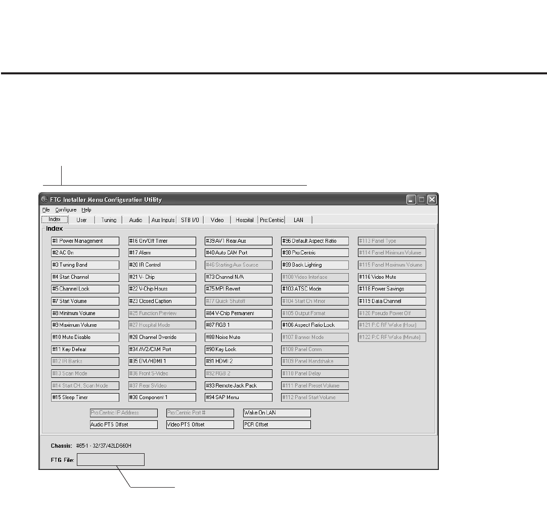
44 206-4200
FTG File Manager Utilities Overview (Cont.)
CONFIGURATION SETTINGS
Select tabs for categories of Installer
Menu items to set up TV.
FTG Installer Menu Conguration Utility
Notes:
• Pro:Centric and LAN tabs enable you to set up parameters equivalent to the Offset Setup and
Pro:Centric Menus described under “IP Environment Setup” on pages 45 and 46 of this document.
Refer to the Free-To-Guest (FTG) File Manager User Guide for further information on these tabs.
• The Start Channel item (#4) in the Tuning tab for these models allows you to assign an IP start
channel.
• The Hospital tab contains setup items that are applicable only for hospital-grade TV models.
Filename of opened FTG Configuration
(.rml) file created using FTG Device
Configuration Application.
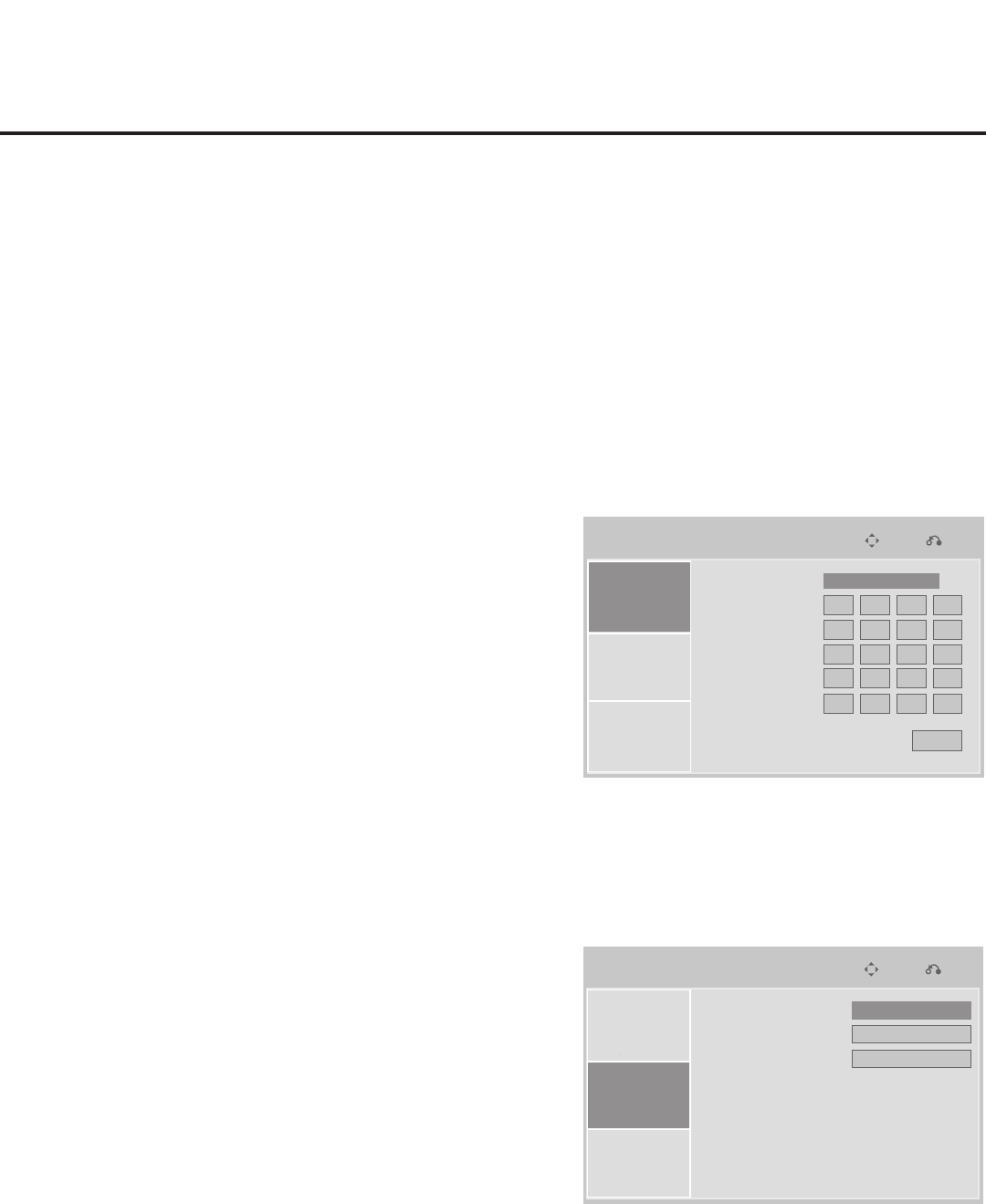
45
206-4200
IP Environment
Prev.
Move
Network Setup
Offset Setup
Pro:Centric
IP Environment
Prev.
Move
Network Setup
Offset Setup
Pro:Centric
IP Environment
Prev.
Move
Network Setup
Offset Setup
Pro:Centric
IP Environment
Prev.
Move
Network Setup
Offset Setup
Pro:Centric
IP Environment
Prev.
Move
Network Setup
Offset Setup
Pro:Centric
IP Environment
Prev.
Move
Network Setup
Offset Setup
Pro:Centric
Audio PTS Offset
Video PTS Offset
PCR Offset
0
0
0
Mode
IP Address
Subnet Mask
Gateway
DNS1
DNS2
MAC Address :
e8:5b:5b:63:97:3e
0
Apply
0 0 0
0 0 0 0
0 0 0 0
0 0 0 0
0 0 0 0
DHCP
►
►
►
►
IP Environment Setup
The IP Environment Menu enables you to set up network features of the TV. Like the Installer Menu, the
IP Environment Menu is editable (with the Installer Remote) only if the TV is in Pass-through or Application
Tuning Mode and read-only when the TV is not in either of these modes.
Access the IP Environment Menu
1. Use the Installer Remote to enter the Installer Menu: Press MENU repeatedly until the on-screen menu
display no longer toggles, and then press 9-8-7-6 + ENTER.
2. Navigate to Installer Menu item 119 DATA CHANNEL, and press 2-5-3 + MENU to launch the IP
Environment Menu (see sample displays below).
Use the Up/Down arrow keys on the Installer Remote to select the desired menu option—Network Setup,
Offset Setup, or Pro:Centric—and then press ENTER. Refer to the following sections for information on each
of the IP Environment setup options.
Network Setup
If the TV is connected to a network with a DHCP server, by
default the server will automatically assign an IP address to the
TV. The Network Setup Menu options enable you to set up static
IP/network connections or to revert from static to DHCP settings.
Use the Up/Down arrow keys to navigate between elds.
1. With Network Setup selected, use the Left/Right arrow keys
on the Installer Remote to select Static or DHCP in the Mode
eld.
2. (Static IP/network connections only) Complete the IP Address,
Subnet Mask, Gateway, DNS1, and DNS2 elds. Either key
in or use the Left/Right arrow keys to select the appropriate
values.
3. When you have completed all elds as necessary, navigate to
Apply, and then press ENTER.
4. Press MENU to return to TV viewing, or press RETURN to
return to the previous menu level.
Offset Setup
If necessary, due to an audio and/or video stream delay, the
Offset Setup Menu options enable you to compensate for
synchronization irregularities by allowing audio PTS, video PTS,
and PCR offset modications. Note that any offset modications
should be performed by qualied personnel only.
1. With Offset Setup selected, use the Up/Down arrow keys on
the Installer Remote to navigate to the appropriate eld: Audio
PTS Offset, Video PTS Offset, or PCR Offset.
2. Use the Left/Right arrow keys to set the appropriate offset
value for the selected eld. Offset values are represented in
10 ms intervals to 500 ms or -500 ms.
3. When you have completed all modications as required,
press MENU to return to TV viewing, or press RETURN to
return to the previous menu level.

46 206-4200
IP Environment
Prev.
Move
Network Setup
Offset Setup
Pro:Centric
IP Environment
Prev.
Move
Network Setup
Offset Setup
Pro:Centric
IP Environment
Prev.
Move
Network Setup
Offset Setup
Pro:Centric
Mode
Media Type
Server IP
Port Number
Wake On Lan
Data Channel
Wake On RF
Wake On Time
Off
►
►
0 0 0 0
12 00
RF
0
Off
0
Off
:
IP Environment Setup (Cont.)
Pro:Centric Setup
The Pro:Centric Menu options enable you to congure
Pro:Centric server settings in the TV. With Pro:Centric selected,
use the Up/Down arrow keys to navigate between elds.
Note: Options that are initially grayed out/inaccessible in the
Pro:Centric Menu are dependent upon other settings in the
display. For example, if “IP” is selected in the Media Type eld,
the Server IP and Port Number elds become accessible.
Note: For those elds that permit direct entry of numerical values
(for example, Port Number, Data Channel, etc.), once you key in
the maximum number of digits allowed in the highlighted eld, the
next available eld will be highlighted.
AM
1. To enable/disable Pro:Centric application operation on a TV, use the Left/Right arrow keys on the
Installer Remote to select the appropriate setting—Off, FLASH, or GEM—in the Mode eld.
Note: If the mode has already been set in the Installer Menu (Installer Menu item 098 PRO:CENTRIC),
the specied mode will be reected in this eld. If you change the mode in this menu, Installer Menu
item 098 will now reect the value you entered here.
2. In the Media Type eld, use the Left/Right arrow keys to select IP or RF, as required.
Note: Setting the Media Type to “IP” automatically sets the Data Channel eld to “253.” You cannot
alter this setting (unless you revert to RF media). It is not possible to direct enter “253” in the Data
Channel eld.
3. (IP media only) Complete the Server IP and Port Number elds for TV E-Z Installation (splash screen,
conguration, and rmware) data. The Server IP must be an IPv4 multicast address within the
designated range of 224.0.0.0 to 239.255.255.255.
Either key in or use the Left/Right arrow keys to select the appropriate values in each eld. Note that
the port number (ve digits maximum) must match exactly the port number that has been set in the
Pro:Centric RF/IP Conguration display in the Admin Client (refer to the Pro:Centric™ Server Admin
Client User Guide for further information).
4. In the Wake On LAN field, use the Left/Right arrow keys to select On or Off, as required. The Wake On
LAN feature enables the TV to receive software updates via the LAN while the TV is in standby mode.
5. (RF media only) In the Data Channel eld, either key in or use the Left/Right arrow keys to select the
RF channel number of the data channel for Pro:Centric or E-Z Installation (splash screen, congura-
tion, or rmware) data. The data channel must be between 0 (disabled) and 135.
The TV may take several minutes to load EPG data after AC power is initially applied.
Note: If the data channel has already been set in the Installer Menu (Installer Menu item 119 DATA
CHANNEL), the specied channel will appear in this eld. If you change the data channel in this menu,
Installer Menu item 119 will now show the value you entered here.
6. (RF media only) In the Wake On RF eld, use the Left/Right arrow keys to select On or Off, as
required. The Wake On RF feature enables the TV to receive software updates via RF while the TV is
in standby mode. If you set Wake On RF to “On,” specify the appropriate Wake On time in the Wake On
Time eld. Note that the Wake On time is based on a 12-hour clock. Ensure the AM/PM specication is
set accordingly.
7. Once all elds are completed as required, press MENU to return to TV viewing, or press RETURN to
return to the previous menu level.
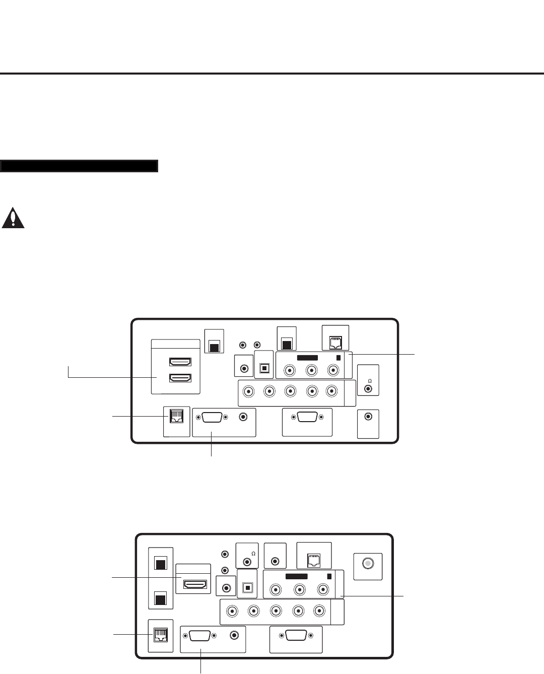
47
206-4200
Remote Jack Pack / TV Connections & Setup
COMPONENT
IN
RS-232C IN
(SERVICE ONLY)
UPDATE
RESET
AUDIO IN
(RGB/DVI)
.....
....
RL
P
B
Y P
R
1
HDMI/DVI IN
OPTICAL
DIGITAL
INTERFACE
VIDEO L/MONO-AUDIO-R
AV IN 1
RGB IN (PC)
.....
.....
.....
LAN2
TV-LINK CFG
GAME CONTROL
/MPI
..........
AUDIO OUT
SERVICE
ONLY
SPEAKER
OUT
(8 )
LAN1
RJP
ANTENNA IN
HDMI/DVI IN 1
Connect HDMI
connector from
RJP cable bundle.
AUDIO/VIDEO IN 1
Connect Composite Video/
Audio connectors from RJP
cable bundle. (Composite
Video on legacy RJP only.)
RJP INTERFACE
Connect RJ-45
Control cable from
RJP cable bundle.
COMPONENT
IN
RS-232C IN
(SERVICE ONLY)
UPDATE
RESET
AUDIO IN
(RGB/DVI)
.....
....
RL
P
B
Y P
R
..........
2
1
HDMI/DVI IN
OPTICAL
DIGITAL
RJP
INTERFACE
VIDEO L/MONO-AUDIO-R
AV IN 1
RGB IN (PC)
.....
.....
.....
LAN2
TV-LINK CFG
GAME
CONTROL/MPI
..........
AUDIO OUT
SERVICE
ONLY
SPEAKER
OUT
8
LAN1
HDMI/DVI IN 1
Connect HDMI
connector from
RJP cable bundle.
RJP INTERFACE
Connect RJ-45
Control cable from
RJP cable bundle.
RGB IN (PC)
Connect RGB connector from RJP
cable bundle (legacy RJP only).
AUDIO/VIDEO IN 1
Connect Composite Video/
Audio connectors from RJP
cable bundle. (Composite
Video on legacy RJP only.)
LD660H/LD665H Jack Panel
LV555H Jack Panel
Remote Jack Pack Setup
RJP Available? If you will use a Remote Jack Pack (RJP) in your system, set Installer Menu item 093
RJP AVAILABLE appropriately (for example, on a legacy model RJP: HDMI Mode, set RJP AVAILABLE
to 001). See Installer Menu detailed descriptions for further information.
TV Connections
Make these connections ONLY after Master TV Setup and TV cloning procedures are
complete.
Refer to the appropriate figure below, and connect the RJ-45 Control cable from the RJP cable bundle to
the RJP INTERFACE port on the TV’s jack panel. Then, connect HDMI, RGB, and Composite Video/
Audio connectors, as applicable, for the cable bundle.
093 RJP AVAILABLE 001
RGB IN (PC)
Connect RGB connector from RJP
cable bundle (legacy RJP only).
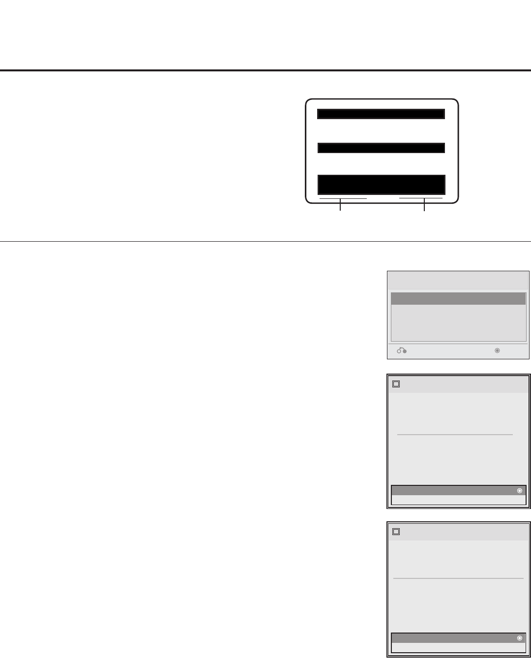
48 206-4200
Reference: Upgrading TV/PTC Software using a USB Memory Device
Upgrading TV/PTC Software
Before you begin, note that the software upgrade les must be stored in a
folder named “LG_DTV” in the root directory of the USB memory device.
Also, ensure the USB device has been formatted with FAT format.
Note for TV Software Upgrade only: If the TV detects a later version
of software on the USB device, it will automatically display a dialog from
which you can start the software upgrade immediately. Otherwise, you can
close the dialog, and access the USB Download Menu as described below.
1. Turn the TV ON.
2.
Plug the USB memory device into the USB IN port on the TV.
3.
Press MENU on the Installer Remote to display the TV setup menus
(TV is in Pass-through Mode) or the Function Menu (TV is not in
Pass-through Mode).
4. Use the arrow navigation keys to select/highlight either the Option
menu icon from the TV setup menus or the Lock menu icon from the
Function Menu. Then, press the number “7” key a total of seven times
to display the USB Download Menu.
5. Use the Up/Down arrow keys to select Upgrade TV Software or
Upgrade PTC Software, as applicable, and press ENTER. (See
screen samples at right.)
6. Use the Up/Down arrow keys to select the upgrade to install, and then
press ENTER.
The TV will show update completion progress in a new window. Do NOT
remove the USB device until the software upgrade is complete. When a
TV software upgrade is complete, the TV will reset itself with an automatic
restart. When a PTC upgrade is complete, the TV will turn OFF.
Checking the Software Versions
You can check the software versions of the TV by
accessing the Installer Menu with the Installer
Remote: Press MENU repeatedly until the on-screen
menu display no longer toggles, and then press
9-8-7-6 + ENTER.
When you are finished, press ENTER again to exit
the Installer Menu.
Typical Installer
Menu
CPU VersionPTC Version
The following software files are found in the memory card.
[ Current TV Software Version Information ]
epak : 3.13.0
mtdinfo(RELEASE) : 0.00.0
model(RELEASE) : 3.13.0
ezcal(RELEASE) : 3.13.0
lgfont(RELEASE) : 3.13.0
TV Software Update
i
Upgrade PTC Software
i
boot(RELEASE) : 0.00.1
rootfs(RELEASE) : 0.00.1
emanual(RELEASE) : 0.00.3
kernel(RELEASE) : 3.13.0
micom(RELEASE) : 0.d0.b8
The following software files are found in the memory card.
Select the file you want to download to this TV
or press EXIT to cancel the update.
EPK : 3.14.00
xxLD660H_v3.14.00
xxLD660H_v1.00.014
[ Current TV Software Version Information ]
epak : 3.13.0
mtdinfo(RELEASE) : 0.00.0
model(RELEASE) : 3.13.0
ezcal(RELEASE) : 3.13.0
lgfont(RELEASE) : 3.13.0
TV Software Update
i
boot(RELEASE) : 0.00.1
rootfs(RELEASE) : 0.00.1
emanual(RELEASE) : 0.00.3
kernel(RELEASE) : 3.13.0
micom(RELEASE) : 0.d0.b8
The following software files are found in the memory card.
Select the file you want to download to this TV
or press EXIT to cancel the update.
EPK :
SPLASH.bmp
USB Download Menu
Upgrade TV Software
Upgrade PTC Software
Teach To TV (TLL)
Teach To TV (TLX)
Return Enter
xxLD66xH PTC INSTALLER MENU
000 INSTALLER SEQ 000
UPN 000-000-000-000 ASIC D279
PTC V1.00.016 CPU V1.21.00
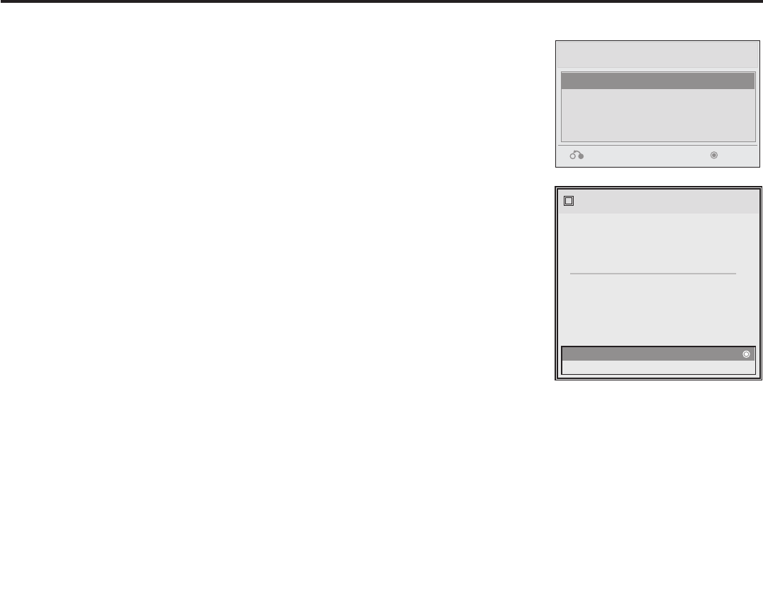
49
206-4200
Reference: Downloading a Splash Screen using a USB Memory Device
Splash Screen Image File Guidelines
• The splash screen image must be a 24-bit (RGB 8 x 8 x 8) BMP.
• The image should be no larger than 3 MB.
• The ideal resolution for the image is 1366 x 768 pixels or under.
• The image le must be stored in a folder named “LG_DTV” in the root
directory of USB memory device.
• Ensure the USB device has been formatted with FAT format.
Downloading a Splash Screen Image
1. Turn the TV ON.
2.
Plug the USB memory device into the USB IN port on the TV.
3.
Press MENU on the Installer Remote to display the TV setup menus
(TV is in Pass-through Mode) or the Function Menu (TV is not in
Pass-through Mode).
4. Use the arrow navigation keys to select/highlight either the Option
menu icon from the TV setup menus or the Lock menu icon from the
Function Menu. Then, press the number “7” key a total of seven times
to display the USB Download Menu.
5. Use the Up/Down arrow keys to select Upgrade TV Software, and
then press ENTER.
6. Use the Up/Down arrow keys to select the image le to download,
and then press ENTER.
The TV will show download completion progress in a new window. Do
NOT remove the USB device until the image download is complete.
When the image download is complete, the TV will reset itself with an
automatic restart. Upon the restart, you should see the new splash
screen.
The following software files are found in the memory card.
[ Current TV Software Version Information ]
epak : 3.13.0
mtdinfo(RELEASE) : 0.00.0
model(RELEASE) : 3.13.0
ezcal(RELEASE) : 3.13.0
lgfont(RELEASE) : 3.13.0
TV Software Update
i
Upgrade PTC Software
i
boot(RELEASE) : 0.00.1
rootfs(RELEASE) : 0.00.1
emanual(RELEASE) : 0.00.3
kernel(RELEASE) : 3.13.0
micom(RELEASE) : 0.d0.b8
The following software files are found in the memory card.
Select the file you want to download to this TV
or press EXIT to cancel the update.
EPK : 3.14.00
xxLD660H_v3.14.00
xxLD660H_v1.00.014
[ Current TV Software Version Information ]
epak : 3.13.0
mtdinfo(RELEASE) : 0.00.0
model(RELEASE) : 3.13.0
ezcal(RELEASE) : 3.13.0
lgfont(RELEASE) : 3.13.0
TV Software Update
i
boot(RELEASE) : 0.00.1
rootfs(RELEASE) : 0.00.1
emanual(RELEASE) : 0.00.3
kernel(RELEASE) : 3.13.0
micom(RELEASE) : 0.d0.b8
The following software files are found in the memory card.
Select the file you want to download to this TV
or press EXIT to cancel the update.
EPK :
SPLASH.bmp
USB Download Menu
Upgrade TV Software
Upgrade PTC Software
Teach To TV (TLL)
Teach To TV (TLX)
Return Enter
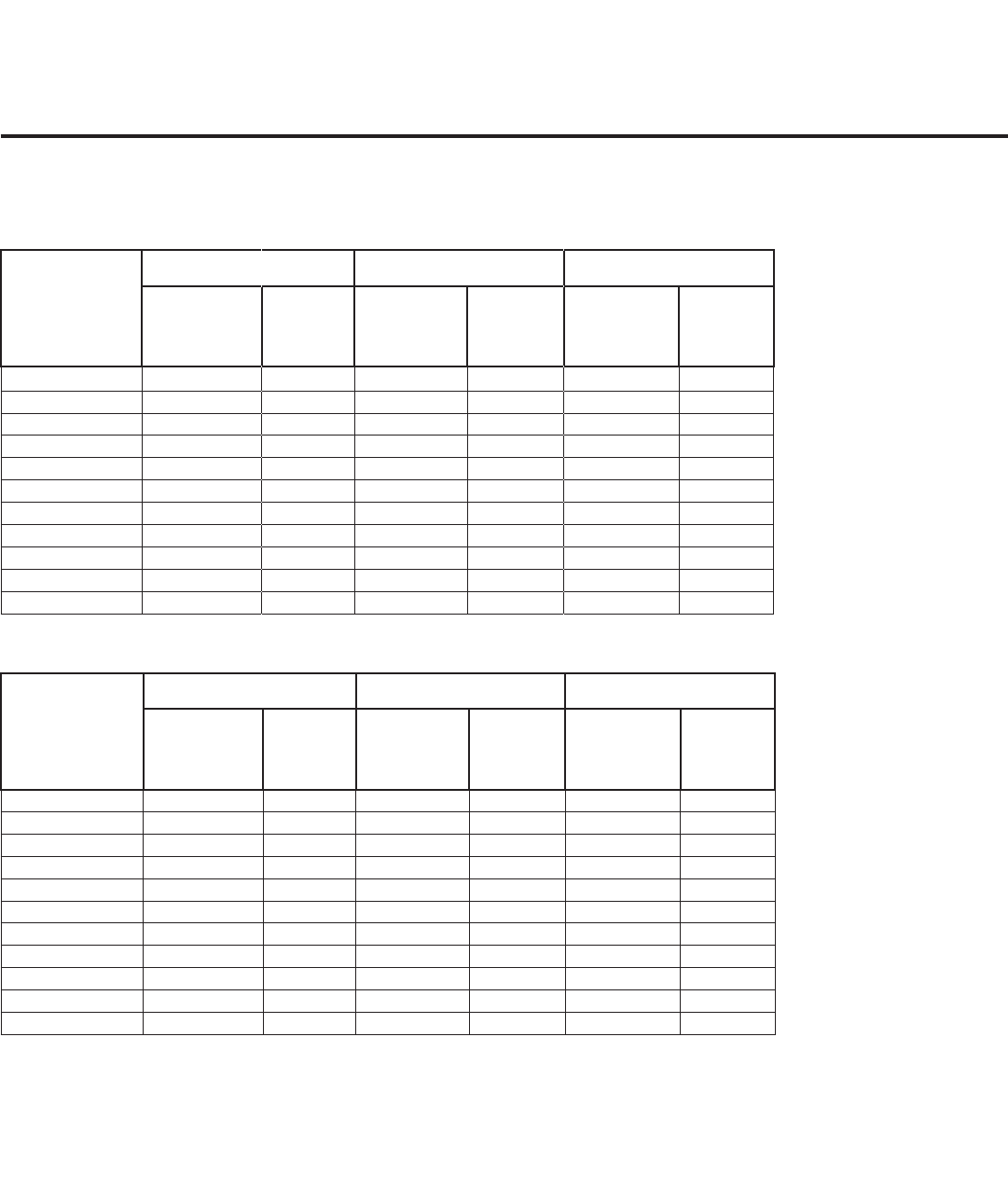
50 206-4200
Reference: Power Consumption Settings
32/37/42LD660H & 32/37/42LD665H
The following tables assume that Installer Menu item 118 POWER SAVINGS is set to 3 (default) and
Installer Menu item 099 BACK LIGHTING is set as shown below (default value is 202).
Note: Values are results of controlled experiments under laboratory conditions.
Item 099
Back Lighting
(Static)
32LD660H / 32LD665H 37LD660H / 37LD665H 42LD660H / 42LD665H
Power
Consumption
(Watts)
Percent
Savings
Power
Consumption
(Watts)
Percent
Savings
Power
Consumption
(Watts)
Percent
Savings
100 88.6 0% 100.7 0% 120.5 0%
90 84.1 5% 95.2 5% 113.1 6%
80 79.0 11% 89.1 12% 105.6 12%
70 74.2 16% 83.4 17% 98.2 19%
60 69.4 22% 77.6 23% 90.8 25%
50 64.2 28% 71.3 29% 83.4 31%
40 59.3 33% 65.5 35% 76.2 37%
30 54.6 38% 60.0 40% 69.2 43%
20 49.6 44% 54.0 46% 61.5 49%
10 45.1 49% 48.7 52% 54.8 55%
1 40.4 54% 43.5 57% 48.2 60%
Item 099
Back Lighting
(Dynamic)
32LD660H / 32LD665H 37LD660H / 37LD665H 42LD660H / 42LD665H
Power
Consumption
(Watts)
Percent
Savings
Power
Consumption
(Watts)
Percent
Savings
Power
Consumption
(Watts)
Percent
Savings
200 53.3 40% 61.3 39% 70.3 42%
190 51.6 42% 59.5 41% 67.6 44%
180 50.5 43% 57.5 43% 65.8 45%
170 48.6 45% 55.6 45% 63.4 47%
160 47.8 46% 53.6 47% 61.1 49%
150 46.6 47% 52.0 48% 59.2 51%
140 45.0 49% 50.2 50% 56.5 53%
130 43.9 50% 47.9 52% 54.1 55%
120 42.3 52% 46.0 54% 51.9 57%
110 41.3 53% 44.5 56% 49.8 59%
101 40.3 55% 43.0 57% 47.9 60%
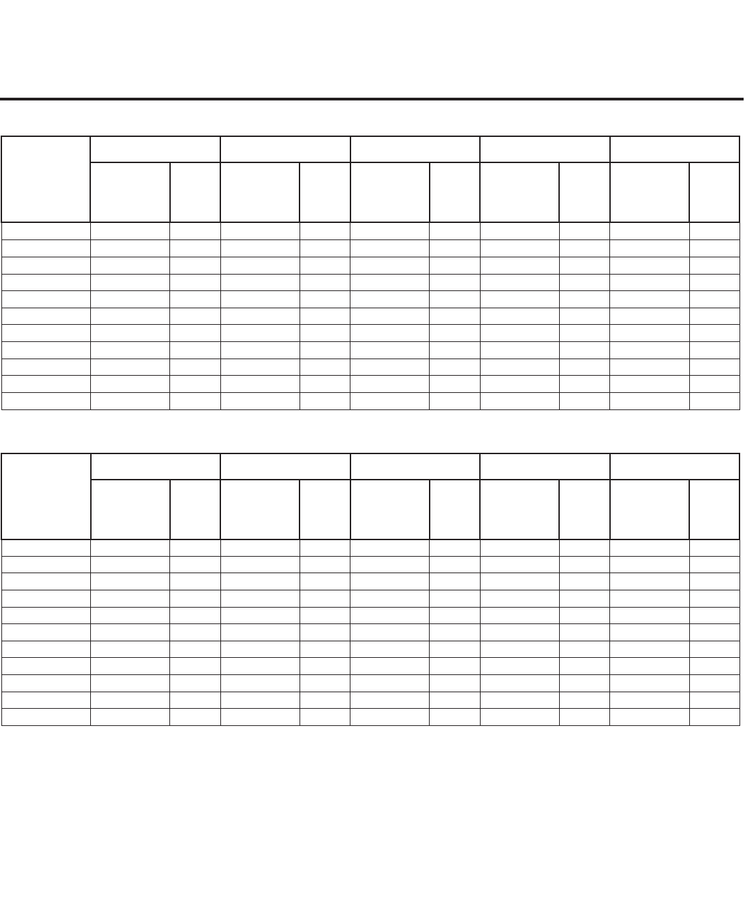
51
206-4200
Reference: Power Consumption Settings (Cont.)
32/37/42/47/55LV555H
Item 099
Back Lighting
(Static)
32LV555H 37LV555H 42LV555H 47LV555H 55LV555H
Power
Consumption
(Watts)
Percent
Savings
Power
Consumption
(Watts)
Percent
Savings
Power
Consumption
(Watts)
Percent
Savings
Power
Consumption
(Watts)
Percent
Savings
Power
Consumption
(Watts)
Percent
Savings
100 47.6 0% 72.5 0% 105.3 0% 113.1 0% 90.1 0%
90 46.8 2% 69.9 4% 100.3 5% 107.5 5% 87.9 2%
80 46.1 3% 67.0 8% 95.2 10% 101.1 11% 85.7 5%
70 45.4 5% 64.3 11% 90.4 14% 95.7 15% 84.2 7%
60 44.9 6% 61.6 15% 85.7 19% 90.2 20% 82.5 8%
50 43.8 8% 58.8 19% 80.6 23% 84.6 25% 79.4 12%
40 42.7 10% 56.0 23% 75.8 28% 79.2 30% 75.9 16%
30 41.5 13% 53.4 26% 71.1 32% 73.8 35% 72.6 19%
20 40.4 15% 50.6 30% 66.0 37% 68.1 40% 69.5 23%
10 39.4 17% 47.9 34% 61.2 42% 62.8 44% 66.1 27%
1 38.3 20% 45.2 38% 56.5 46% 57.6 49% 62.7 30%
Item 099
Back Lighting
(Dynamic)
32LV555H 37LV555H 42LV555H 47LV555H 55LV555H
Power
Consumption
(Watts)
Percent
Savings
Power
Consumption
(Watts)
Percent
Savings
Power
Consumption
(Watts)
Percent
Savings
Power
Consumption
(Watts)
Percent
Savings
Power
Consumption
(Watts)
Percent
Savings
200 45.9 4% 53.2 27% 72.5 31% 75.4 33% 85.2 5%
190 45.1 5% 52.4 28% 70.8 33% 73.2 35% 82.3 9%
180 44.3 7% 51.7 29% 69.1 34% 71.4 37% 79.9 11%
170 43.4 9% 50.8 30% 67.4 36% 69.2 39% 77.5 14%
160 42.6 11% 50.2 31% 65.7 38% 67.9 40% 75.1 17%
150 41.9 12% 49.7 31% 64.3 39% 66.0 42% 73.4 19%
140 41.1 14% 48.8 33% 62.0 41% 64.2 43% 71.1 21%
130 40.2 16% 48.1 34% 60.9 42% 62.6 45% 68.7 24%
120 39.4 17% 47.0 35% 59.2 44% 60.4 47% 66.3 26%
110 38.8 18% 46.6 36% 57.9 45% 58.7 48% 64.7 28%
101 38.0 20% 46.0 37% 56.4 46% 57.4 49% 62.6 31%
Note: Values are results of controlled experiments under laboratory conditions.

52 206-4200
Reference: TV Camport Auto Sense Operation
The Camport Auto Sense function is enabled when:
1. Installer Menu item 034 CAMPORT EN is set to 1 AND
2. Installer Menu item 040 AUTO CAMPORT is enabled (1).
Selectable: Can be accessed with INPUT key, direct
access, etc.
Auto Sense: TV switches to this input when connector is
inserted. The Camport (Side [AV IN 2] Video) has the
highest priority and will override any commands including
tuning to the Start Channel.
CAMPORT (Side Video) Functionality Control
Item 034
CAMPORT EN
Item 040
AUTO CAMPORT
Side (AV IN 2)
Video Operation
0 0 Disabled
0 1 Disabled
1 0 Selectable
1 1 Auto Sense
Camport Operation (Pass-through)
When Camport Auto Sense is enabled as above, the TV
will switch from its current source to the Side (AV IN 2)
Video input whenever a plug is inserted into the AV IN 2
Video input.
When the video plug is removed, the TV will switch back to
the previous source that was being displayed before the
plug was inserted. However, if any direct access to an Aux
channel or RF channel is requested while the Camport is
active, then, when the video plug is removed, the TV will
switch to the last requested channel. Source changes
using any Source keys (INPUT) are ignored. Channel Up/
Down and Flashback commands are not Direct Access
tuning commands, and they are also ignored.
Previous State
Before Inserting
CAMPORT
Operation While
CAMPORT is
Active
State Upon
Removal of
CAMPORT
Aux or RF
Channel None Previous Aux
or RF Channel
Aux or RF
Channel Direct Access Last Requested
Aux or RF Channel
Aux or RF
Channel
Ch Up/Down,
Flashback, and
Input Keys
Previous Aux
or RF Channel
Camport Operation (FTG or PPV)
The operation will be similar to that of the Pass-through
Mode. However, when the Channel Map is maintained
external to the PTC (i.e., FTG and PPV), Channel Up/
Down or Flashback keys are sent as Direct Access tuning
commands to the PTC/TV.
Previous State
Before Inserting
CAMPORT
Operation While
CAMPORT is
Active
State Upon
Removal of
CAMPORT
Aux or RF
Channel None Previous Aux
or RF Channel
Aux or RF
Channel Direct Access Last Requested
Aux or RF Channel
Aux or RF
Channel
Ch Up/Down,
Flashback, and
Input Keys
Last Requested Aux
or RF Channel

53
206-4200
Reference: TV Aux Input Configuration
DIRECT ACCESS
Tuning TV
ENABLE MPI DATA
START AUX
SOURCE
ASSIGN-
MENT
Installer Menu
MPI DATA
STATUS TYPE
0x41 SOURCES
ENABLED (R/W)
DATA STATUS
TYPE 0xD2
CURRENT AV
SOURCE (R)
DATA STATUS
TYPE 0x0D
AUX
SOURCE (R)
OLD_
OCV = 0
OLD_
OCV = 1
Source
Input
Source
Mode
Number Labeling Value Labeling Value Labeling
130 90 Video2
(Side)
CV/SVIDEO 34 CAMPORT_EN 0x01 Video Front
(Camport)
0 Video Front
(Camport)
0 (VIDEO) 2
131 91 Video1
(Rear)
CV/SVIDEO 39 REAR_AUX_EN 0x02 Rear Video
(Aux)
1 Rear Video
(Aux)
0 (VIDEO) 1
132 92 HDMI2 DTV/PC 91 YPrPb2 EN = 1 0x04 S-Video
Rear
2 S-Video Rear 0 (VIDEO) 5
133 93 HDMI1/DVI DTV/PC 35 COMPPORT_EN
= 1
0x08 Front
Computer
3 Front
Computer
0 (VIDEO) 3
134 94 RGB PC 87 REAR RGB EN
= 2
0x10 SVGA Rear
Computer
4 SVGA Rear
Computer
2
(COMPUTER)
4
136 96
Component
38 YPrPb EN 0x40 Y/UV
Component
6 Rear Y/PrPb
Component
Video
0 (VIDEO) 6

54 206-4200
A b-LAN enabled head end device, such as an LG FMA-LG101, broadcasts over the RF distribution system to
communicate to multiple TVs. When the TV is first installed, it must be turned ON in order for its embedded
b-LAN module to receive communication from the head end device. At this point, if it is desired for the b-LAN
module to always be powered, including while the TV is in Standby, set Installer Menu item 118 POWER
SAVINGS to 001.
Also, if MPI communication is required for external MPI control, set Installer Menu item 118 POWER SAVINGS
to 001 so that the GAME CONTROL/MPI port circuitry is always powered.
Reference: b-LAN Setup & Overview
POWER
SAVINGS
001 On On
003 (default) Off On
The b-LAN module is internal to the TV. It allows hotel/institution head end equipment with b-LAN technology
to communicate, via the institution’s RF distribution system, with the TV for configuration and control.
Note: MPI cards with b-LAN technology—LMT7Z5, LMT7Z7, LMT7Z9—are NOT supported in TVs in which
b-LAN technology is already integrated.
Installer Menu item 118 POWER SAVINGS controls the power circuitry for both the embedded b-LAN module
and the GAME CONTROL/MPI port. The default value is 003—the b-LAN module as well as the GAME
CONTROL/MPI port circuitry is only powered when the TV is turned ON. See chart below.
TV Power On State
TV Standby State
b-LAN & GAME
CONTROL/MPI Port
Power
b-LAN & GAME
CONTROL/MPI Port
Power

55
206-4200
Reference: RJP Model List and Input Auto-sensing Hierarchy
RJP Model List
Legacy Models Scaler Models
RJP-101M RJP-201M
RJP-101ML N/A
RJP-110F RJP-210F
RJP-110FW RJP-210FW
RJP-110W RJP-210W
RJP-110WBR RJP-210WBR
RJP-110S RJP-210S
RJP-120G RJP-220G
RJP-120T RJP-220T
RJP-201B RJP-301B
RJP-202B RJP-302B
RJP Input Auto-sensing Hierarchy
Priority Video Audio
1st (Highest) Digital Video In Audio In (3.5mm)
2nd PC Video In Audio In (L/R)
3rd Video In Digital Video In

56 206-4200
This section describes how to reset factory defaults either on a single TV that is currently in Pass-through
or FTG Mode or on multiple TVs that are currently in FTG Mode.
Note: If the TV(s) is/are currently in FTG Mode, restoring the factory defaults also resets the TV to Pass-
through Mode.
Installer Menu Item 117 FACT DEFAULT
If the TV is currently in Pass-through Mode, you can set Installer Menu item 117 FACT DEFAULT to 001 to
reload the factory defaults and clear the channel lineup, including any assigned channel icons and custom
text labels.
Factory “IN-STOP”
If the TV is currently in FTG Mode, a predened value for Installer Menu item 117 FACT DEFAULT
enables access to initiate a factory “IN-STOP” process that will reset the TV to Pass-through Mode in
addition to restoring all factory defaults. Contact technical support for the required value for Installer Menu
item 117 and for additional information on performing the IN-STOP from the Installer Menu.
Additional FTG Mode via CPU Options
There are two additional options for resetting Pass-through Mode/factory defaults on TVs that are in FTG
Mode via the CPU. The rst enables you to reset a single TV to Pass-through Mode, while the second
enables you to reset multiple TVs to Pass-through Mode at one time.
• Using a USB memory device, “Teach” an FTG Conguration (.tlx) le that only contains a “0 Mapped
Channels” FTG Channel Map to the TV. Refer to “Creating an FTG Conguration File using the FTG File
Manager” and “Teaching FTG Conguration to a TV” on pages 35 to 37, respectively, for further informa-
tion.
• If your system uses a Pro:Centric server for remote management/administration, use the Pro:Centric
Admin Client to load an FTG Conguration (.tlx) le that only contains a “0 Mapped Channels” FTG
Channel Map on the Pro:Centric server. Refer to the Pro:Centric™ Server Admin Client User Guide
for further information.
Additional FTG Mode via EBL Options
There are two additional options for resetting Pass-through Mode/factory defaults on TVs that are in FTG
Mode via the EBL. The rst enables you to reset a single TV to Pass-through Mode, while the second
enables you to reset multiple TVs to Pass-through Mode at one time.
Note: While the IN-STOP process described above will clear both the PTC and the CPU, both
options below only clear the PTC. Thus, the current Channel Map and TV setup menu settings
will remain in the CPU after the reset is completed.
• Using a direct PC-to-TV connection, “Write” an unpopulated Channel Map—that is, a Channel Map with
zero channels—to the TV. Refer to the “FTG Mode via EBL” procedure on page 40 and/or the Free-To-
Guest (FTG) Configuration Application manual for further information.
• If your system uses an FMA for remote management/broadcast conguration, congure the FMA device
with an FMA Conguration le that only contains a “0 Mapped Channels” FTG Channel Map to broad-
cast to the TV EBL(s). Refer to the Free-To-Guest (FTG) Configuration Application manual and/or the
Installation & Setup manual for the FMA device for further information.
Reference: Resetting Factory Defaults on the TV(s)
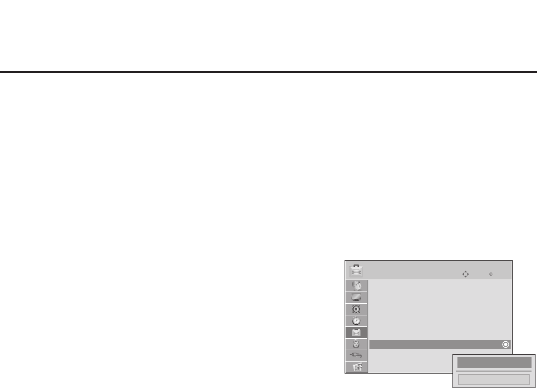
57
206-4200
Reference: TV Zone Restrictions
Enter
Move
OPTION
Menu Language : English
Audio Language : English
Caption : Off
Set ID : 1
Demo Mode : Off
Zone : 0
Close
1►
►
The FTG Channel Map Editor in the FTG File Manager’s FTG Channel Map Conguration Utility enables
you to assign Zone restrictions to channels that may be deemed unsuitable for certain locations, for
example, a hotel lobby. In the FTG Channel Map Editor, a Zone # (for example, “1”) must be designated for
each channel that is to be restricted.
On location, set the Zone # for all the TVs in a select area, or “Zone” (for example, the lobby) so that the
TVs can omit channels that have been restricted in the FTG Channel Map. However, note that while a chan-
nel can be restricted from up to eight Zones, a TV can only ever be in (set for) one Zone. TV Zone 0 is the
default TV Zone #. When the TV Zone is 0, the TV will ignore any restriction that may be placed on channels
in the FTG Channel Map.
See the FTG Channel Map Editor overview on page 43. Also, see the Free-To-Guest (FTG) File Manager
User Guide for more detailed information on assigning Zone restrictions.
Use the following procedure to specify a Zone designation for a TV.
1. Press MENU on the Installer Remote, and use the arrow
navigation keys to select/highlight the OPTION menu option.
Then, press ENTER.
2. Use the Up/Down arrows to select Zone, and then press
ENTER.
3. In the Zone pop-up window, use the Left/Right arrows to
select the appropriate Zone number. Then, press ENTER.
4. Press MENU to return to TV viewing, or press RETURN to
return to the previous menu level.
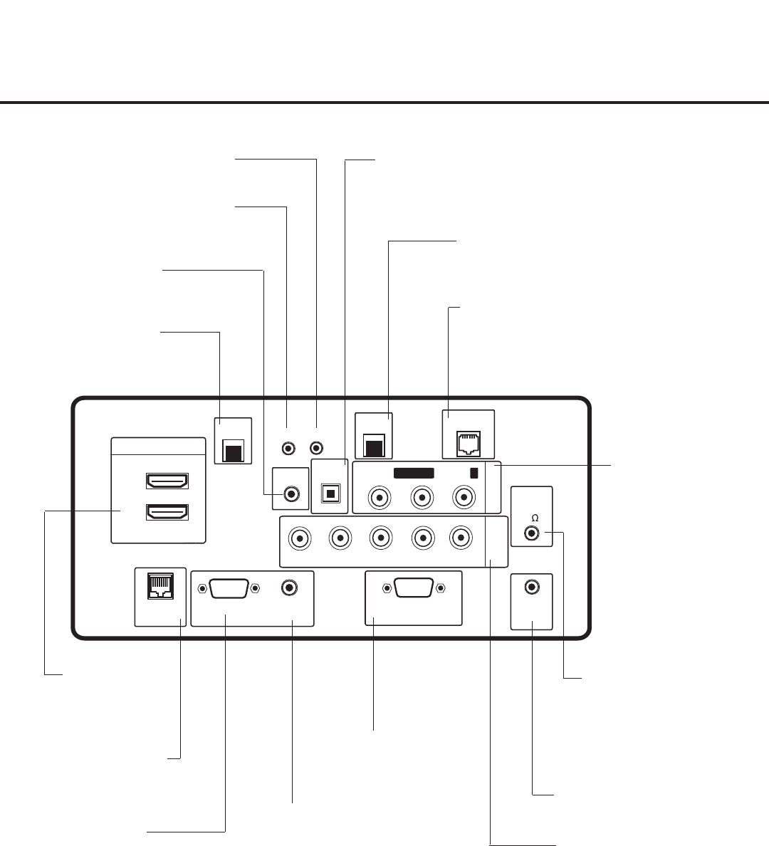
58 206-4200
COMPONENT
IN
RS-232C IN
(SERVICE ONLY)
UPDATE
RESET
AUDIO IN
(RGB/DVI)
.....
....
RL
P
B
Y P
R
..........
2
1
HDMI/DVI IN
OPTICAL
DIGITAL
RJP
INTERFACE
VIDEO L/MONO-AUDIO-R
AV IN 1
RGB IN (PC)
.....
.....
.....
LAN2
TV-LINK CFG
GAME
CONTROL/MPI
..........
AUDIO OUT
SERVICE
ONLY
SPEAKER
OUT
8
LAN1
Reference: LD660H/LD665H Rear Jack Panel
LAN 2
Use for video IP and/or
network connections.
RGB IN (PC)
Connection for RGB
output from PC.
TV-LINK CFG
Use for direct PC-to-TV
FTG configuration.
UPDATE
Restricted to software updates.
RESET
Initiates a hardware reset and
switches the TV to standby.
GAME CONTROL/MPI
When the TV/EBL is in Pass-through Mode, the MPI
function enables an external MPI control device (i.e.,
clone programmer, VOD/PPV STB, etc.) to control the
TV. Game Control—EBL in LodgeNet PPV Mode only.
OPTICAL DIGITAL AUDIO OUT
Use for amps and home theater systems.
Note: In Standby Mode, this port is not
enabled.
AUDIO/VIDEO IN 1
Connection for composite
audio/video output from
external device.
SPEAKER OUT (8Ω) *
Connect to 8 ohm self-powered
speaker input. Intended for
special applications, such as a
powered bathroom speaker
with volume control.
RS-232C IN
Use for downloading
software updates, etc.
COMPONENT IN
Connection for component
output from external device.
AUDIO IN (RGB/DVI)
Audio connection for
RGB or DVI device.
RJP INTERFACE
Connection for Remote Jack
Pack (RJP) Control cable.
HDMI/DVI IN
Connection for
HDMI/DVI output
from external device.
* This stereo jack provides a mono speaker fixed-level,
1 watt output (audio +, audio -, w/ground shield). Do NOT
plug in a mono connector, as this may damage the TV.
LAN 1
Use for video IP and/or
network connections.
SERVICE ONLY
Restricted to software updates.
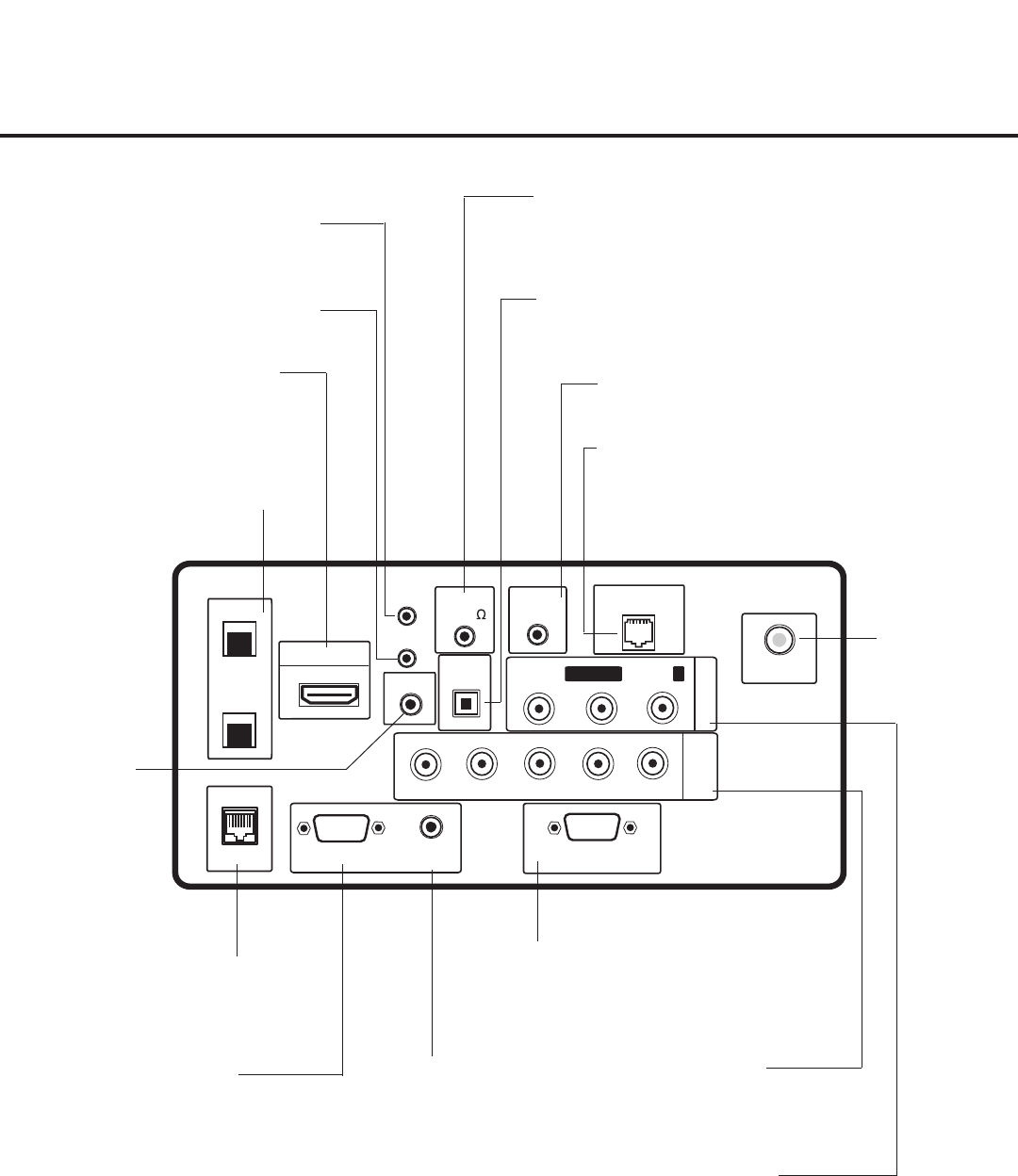
59
206-4200
COMPONENT
IN
RS-232C IN
(SERVICE ONLY)
UPDATE
RESET
AUDIO IN
(RGB/DVI)
.....
....
RL
PBY PR
1
HDMI/DVI IN
OPTICAL
DIGITAL
INTERFACE
VIDEO L/MONO-AUDIO-R
AV IN 1
RGB IN (PC)
.....
.....
.....
LAN2
TV-LINK CFG
GAME CONTROL
/MPI
..........
AUDIO OUT
SERVICE
ONLY
SPEAKER
OUT
(8 )
LAN1
RJP
ANTENNA IN
Reference: LV555H Rear Jack Panel
AUDIO IN (RGB/DVI)
Audio connection for
RGB or DVI device.
COMPONENT IN
Connection for component
output from external device.
LAN1/LAN2
Use for video IP and/or
network connections.
AUDIO/VIDEO IN 1
Connection for composite
audio/video output from
external device.
SPEAKER OUT (8Ω) *
Connect to 8 ohm self-powered speaker input.
Intended for special applications, such as a powered
bathroom speaker with volume control.
TV-LINK CFG
Use for direct
PC-to-TV FTG
configuration.
RS-232C IN
Use for downloading
software updates, etc.
UPDATE
Restricted to software updates.
GAME CONTROL/MPI
When the TV/EBL is in Pass-through Mode, the MPI
function enables an external MPI control device (i.e.,
clone programmer, VOD/PPV STB, etc.) to control the
TV. Game Control—EBL in LodgeNet PPV Mode only.
OPTICAL DIGITAL AUDIO OUT
Use for amps and home theater systems.
Note: In standby mode, this port is not enabled.
RJP INTERFACE
Connection for Remote Jack
Pack (RJP) Control cable.
HDMI/DVI IN
Connection for HDMI/DVI
output from external device.
RESET
Initiates a hardware reset and
switches the TV to standby.
ANTENNA IN
Connect to
Antenna/CATV.
SERVICE ONLY
Restricted to software updates.
RGB IN (PC)
Connection for RGB
output from PC.
* This stereo jack provides a mono speaker fixed-level,
1 watt output (audio +, audio -, w/ground shield). Do NOT
plug in a mono connector, as this may damage the TV.
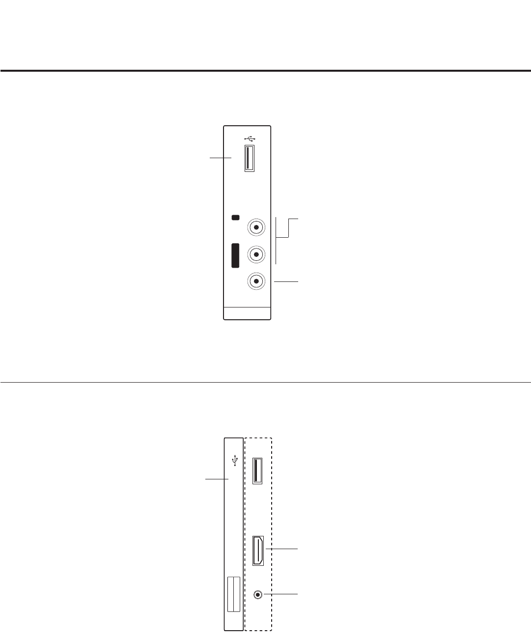
60 206-4200
Reference: Side Connections Panel
AV IN 2
L/MONO -AUDIO- R
VIDEO USB IN
USB IN
AV IN 2
VIDEO / AUDIO
..........
HDMI/DVI
IN 2
USB IN
Insert USB memory device
for software updates, cloning
purposes, FTG Mode via CPU
configuration, picture/music
entertainment, etc., as applicable.
VIDEO IN
Connect to video output port on
external device (see Reference
section, “TV Camport Auto
Sense Operation,” for further
information).
L/MONO-AUDIO-R IN
Connect to audio output
jacks on external device.
For only mono audio output,
connect to Left audio input.
A/V 2 Input
AV IN 2
L/MONO -AUDIO- R
VIDEO USB IN
USB IN
AV IN 2
VIDEO / AUDIO
..........
HDMI/DVI
IN 2
LD660H/LD665H TVs
LV555H TVs
USB IN
Insert USB memory device
for software updates, cloning
purposes, FTG Mode via CPU
configuration, picture/music
entertainment, etc., as applicable.
A/V 2 Input
Connect to video/audio output
port on external device (see
Reference section, “TV Camport
Auto Sense Operation,” for
further information).
HDMI/DVI IN 2
Connection for HDMI/DVI
output from external device.
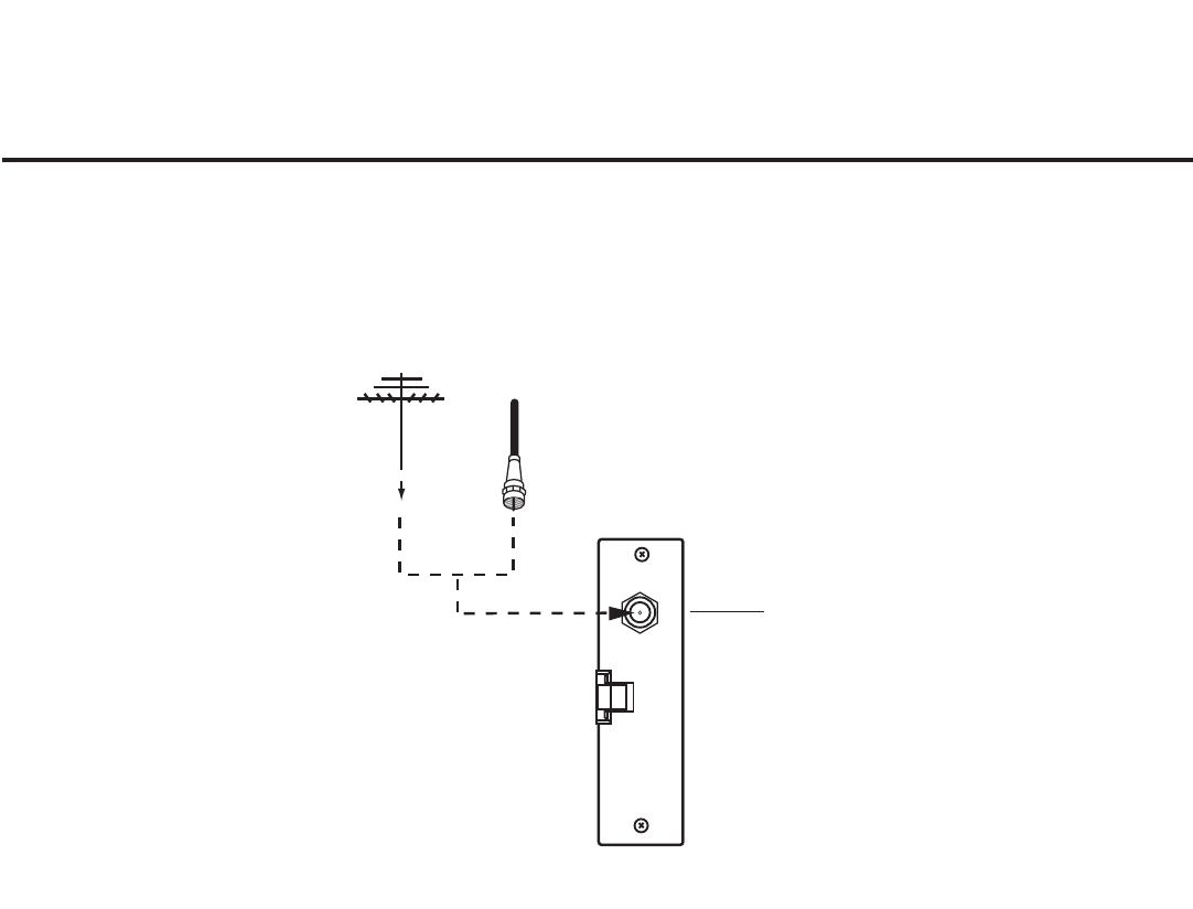
61
206-4200
Antenna
or CATV
ANTENNA IN
LD660H/LD665H TVs only
ANTENNA IN
Connect to Antenna/
CATV.
Note: The Antenna connection for LV555H TVs is located on the rear jack panel (see page 59).
Reference: RF Antenna Connection
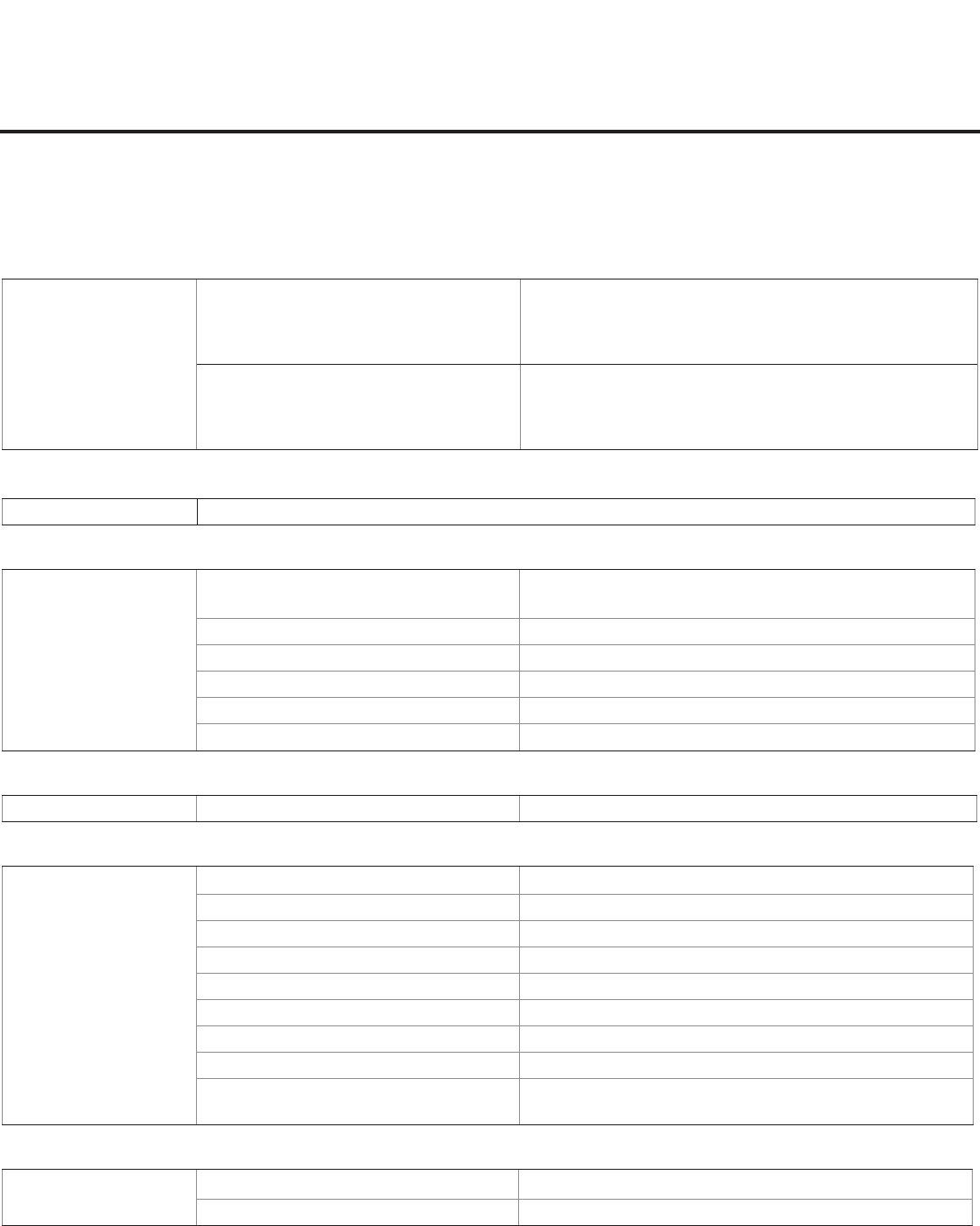
62 206-4200
Troubleshooting
General Troubleshooting
Some Quick and Easy Tips for Resolving Problems
Symptom Possible Cause(s) Possible Solution(s)
Installation
Cannot direct enter
channel number.
(TV in Pass-through Mode) Installer Menu
item 028 CH. OVERIDE is set to 0, i.e.,
disabled (recommended setting).
If Installer Menu item 028 CH. OVERIDE is set to 0, only
channels that are active in the TV’s channel lineup can be
selected. Set CH. OVERIDE to 1 to allow access for direct
keypad entry to all channels.
(TV in FTG Mode) The channel entered is
not part of the FTG Channel Map.
Channel access is restricted to channels included in the FTG
Channel Map. If necessary, make changes to the FTG
Channel Map using the FTG File Manager or the FTG Device
Configuration Application, as appropriate.
Power
No power. See troubleshooting flow chart on following page.
Display Panel Picture
No picture. Display panel is turned OFF. • Turn TV ON.
• Power failure?
Antenna/cable not connected. Connect antenna/cable signal to TV.
Connections incorrect. Check connections on TV.
MPI not connected. If applicable, connect MPI cable to MPI device.
Encrypted program. Try another channel.
Wrong tuning band. Adjust Installer Menu settings.
Erratic Operation
Installer Menu setup. Wrong Installer Menu settings. Adjust Installer Menu settings as required.
Installer Remote
Remote doesn’t work. Remote not in TV Mode. Use MODE key to select “TV”; puts remote into TV Mode.
Not aimed at IR remote sensor. Point remote at IR receiver on TV.
Remote too far from IR sensor. Move remote closer to IR receiver on TV or darken room.
MPI not connected. If applicable, connect MPI cable to MPI device.
IR path to TV’s receiver obstructed. Remove obstructions.
Weak batteries. Replace batteries.
Wrong battery polarity. Check that “+” and “-” match in battery compartment.
Too much light in room. Dim room light.
Wrong Installer Remote. Requires compatible Installer Remote. Contact your LG
dealer.
Picture Reception
Normal picture,
poor or no sound.
Audio muted. Press MUTE or use Volume Up key to increase sound level.
Broadcast problem. Try a different channel.
Note: For other problems not caused by the TV, refer to the other devices’ operating guide(s).
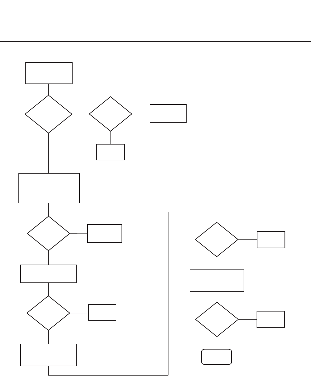
63
206-4200
Controller
Quick Check
STATUS
LED on PTC
Board
blinking?
Plug into AC
Power outlet.
TV
connected
to AC
Power?
Bad
TV
Yes
No No
Yes
Cycle the power by
removing and reconnecting
the AC Power cord. Then,
observe POWER LED
on front of TV.
POWER
LED lit?
No
Yes
Press POWER on
Installer Remote.
TV
responded?
No
Yes
TV
responded?
No
Yes
End
Bad
TV
Bad
PPV Card
Press VOLUME UP/
DOWN or MUTE key on
User-supplied Remote.
Bad Analog or
Digital Board
TV
turned ON?
Yes
No
Press VOLUME UP/
DOWN or MUTE key
on Installer Remote.
Bad
TV
Troubleshooting (Cont.)
Troubleshooting Flowchart
64 206-4200
Troubleshooting (Cont.)
Commercial Mode Check / FTG Operation Troubleshooting
TV turned
ON?
Yes
No
Press POWER on
Installer Remote.
TV is not in Commercial
Mode. Call Technical
Support for assistance.
TV is in
Commercial Mode.
No
On-screen
menu display
no longer
toggles?
Yes
Press MENU repeatedly
as if to access the
Installer Menu.
Function
Menu
on display?
Leave the TV set ON,
and press MENU on the
Installer Remote.
No
TV is in
Commercial Mode.
Yes
Plug into AC
Power outlet.
TV
connected
to AC
Power?
Bad
TV
No
Yes
FTG Operation Troubleshooting
The following table provides troubleshooting information for when the EBL is configured in the FTG Mode of operation.
Symptom Possible Cause(s) Solution(s)
Communication Error
(“Communications
Timeout”)
Cable(s) not connected. Check and connect communication cables.
TV not powered. Check/connect the TV power cord.
TV not turned ON. TV needs to be turned ON (default FTG Mode).
Wrong COM
(communication) port.
In the FTG Device Configuration Application, select the
correct COM port for the cable being used.
Commercial Mode Check
Use this flowchart to determine whether the TV is currently in Commercial Mode.

65
206-4200
Troubleshooting (Cont.)
Clone Programmer Troubleshooting
Caution: Do not connect
a clone programmer to a
PPV card installed in the
Master or Target TVs. Also, if
the TV is in LodgeNet PPV Mode
(check with the site administrator
if you are not certain), do not
connect a clone programmer to
the GAME CONTROL/MPI port.
Either of these actions will
damage the clone programmer
and, if applicable, the PPV card.
• After cloning operations are complete, unplug the TLL-1100A/LT2002 from the TV.
• If the TV does not display a picture (blank screen) after a few seconds, just change channels.
Reset Clone Programmer After Static Shock
After replacing exhausted batteries (LT2002 only), or if the clone programmer
behaves strangely after a static shock:
• TLL-1100A: Turn the TLL-1100A OFF and then ON.
• LT2002: Use a paper clip or similar instrument inserted through the small hole
marked RESET to activate the internal reset switch and restore normal operation.
After a reset, check the real-time clock setting. It may be necessary to set the
clone programmer clock from a TV containing the correct time.
Note: Both the Master and Target TVs must be in Pass-through Mode for cloning
purposes. See also IMPORTANT CLONING INFORMATION on page 24.
Clone Programmer
Symptom Possible Cause(s) Possible Solution(s)
Clone copies setup in less
than 30 seconds.
Not enough time to copy entire
TV setup.
TLL-1100A: Turn the TLL-1100A OFF and then ON.
LT2002: Press RESET on clone programmer.
Then redo Learn/Teach. (Learning usually takes about 90 seconds;
Teaching usually takes 3 to 4 minutes.)
Remote does not operate
clone programmer.
Wrong Installer Remote. Only use an LG Installer Remote to operate clone programmer
with TV.
Clone menu does not dis-
play on TV screen, TLL-
1100A shows error mes-
sage, or LT2002 LED does
not blink.
MPI cord not connected. Connect MPI cord properly, and ensure good connection.
TV not turned ON. TV must be powered ON for clone programmer to work.
(LT2002 only) Weak batteries. Install four (4) fresh AA high-quality alkaline batteries.
(TLL-1100A only) No charge. Ensure the TLL-1100A is fully charged or connected to AC power.
Clone menu hard to read. Weak signal. Connect TV to a reliable analog channel signal source.
No time set. Time not available. Set time on a TV, and copy time to clone programmer.
Clone not working. Clone programmer problem. • Try a different clone programmer.
• Reset the clone programmer.
Clone scans channels
more than once.
Clone should only scan channels
once.
Ensure TV is set up correctly, and try cloning again.
Master and Target TVs
Symptom Possible Cause(s) Possible Solution(s)
Cloning did not work. Procedure interrupted. Wait until procedure complete message is displayed.
Different TV models. Cloning is only possible with identical model TVs.
Step(s) omitted or not performed. Refer to the applicable cloning procedure(s), and make sure all
tasks were performed.
(LT2002 only) Clone time
disappeared.
Batteries were removed. Batteries must remain installed to retain time settings.
New setup not present. Target TV not reset. Disconnect Target TV from AC power for 15 seconds.

66 206-4200
Glossary of Terms
75 OHM RF CABLE
The wire that comes from an off-air
antenna or cable service provider. The
end looks like a hex-shaped nut with a
wire through the middle. It screws onto
the Antenna/Cable threaded jack on the
back of the TV.
300 TO 75 OHM ADAPTER
A small device that connects a 2-wire
300 ohm antenna to a 75 ohm RF jack.
It is usually about an inch long with two
screws on one end and a round opening
with a wire extending out the other end.
A/V CABLES
Audio/Video cables. Three cables
bunched together —right audio (red), left
audio (white), and video (yellow). A/V
cables are used for stereo playback of
videocassettes and for higher quality pic-
ture and sound from other A/V devices.
A/V DEVICE
Any device that produces video or sound
(VCR, DVD, cable box, or television).
AMPLIFIER
An electronic device that amplies sound
from a television, CD player, VCR, DVD
player, or other audio/video device.
ANTENNA
The physical receiver of television signals
sent over the air. A large metal piece of
equipment does not always have to be
visible to be using an antenna.
b-LAN
LodgeNet Interactive Corporation
proprietary RF communication system
used to congure/control TV via RF
distribution system.
CABLE
Cable service box. Refers to the
descrambler box cable subscribers use
to receive cable programming signals.
CATV
Programming provided by a cable
service.
COMPONENT VIDEO
Uses three wires for transporting three-
color video signals. The end result is
usually better video quality.
COMPOSITE VIDEO
Typical video jack, uses one wire for
transporting three-color video signals.
DELETE
Lets you remove channels from the list
that the end user can scroll through
using Channel Up/Down.
DIGITAL TELEVISION
High-resolution, cinema-quality television
signals transmitted digitally.
DVI
Digital Video Interface. Accommodates
analog and digital interfaces with a
single connector.
HDMI
High-denition multi-media interface.
HDSTB
High-denition set top box. Refers to a
tuner device that receives high-denition
television signals which have higher res-
olution than ordinary analog TV signals.
HDTV
High-denition television. Refers to tele-
vision signals that have higher resolu-
tion than ordinary analog TV signals.
INPUT
Refers to the input jack that receives a
signal from a TV, VCR, DVD player, or
other audio/video device.
JACK
An input or output connector on the
back of a TV, VCR, DVD player, or other
audio/video device.
MONO SOUND
Mono (monaural) sound is one channel
of sound. On more than one speaker, all
the speakers play the same audio.
OUTPUT
Refers to the output jack that sends
a signal out of a VCR, DVD player, or
other audio/video device.
PHYSICAL CHANNEL NUMBER
The actual channel number. Analog
channels use the Physical Channel
number and digital channels can use a
Virtual Channel number.
RGB (RED, GREEN, BLUE)
Connection input or output port available
for producing a video image using three
separate colors: Red, Green, and Blue.
RS-232
Serial communication port through
which rmware is downloaded.
2ND AUDIO PROGRAMMING/SAP
Second Audio Programming (SAP) is
another, separate audio channel avail-
able with some programming. Choosing
SAP often refers to listening to audio in
another language, such as Spanish or
French.
SIGNAL
Picture and sound traveling through a
cable, or over the air, to the TV.
STEREO SOUND
Stereo (Stereophonic) sound refers to
audio that’s divided into right and left
sides.
TUNER
Device that picks up the broadcast sig-
nal and turns it into picture and sound.
VIRTUAL CHANNEL NUMBER
A re-mapped channel number. Analog
channels use the Physical Channel
number; however digital channels use a
Virtual (or false) Channel number.
XDS
Extended Data Service. Additional
program information included on the
signal provided at the discretion of the
broadcaster.
A list of denitions for some of the words found in this guide.
Note: Refer to www.atsc.org for further
information.

67
206-4200
Document Revision History / Notes
Notes
Document Revision History
Date Description
October 2011 Revision A: New document
November 2011 Draft B.2: SI/MPI communication updates
Product documentation is available online at: www.LGsolutions.com/products. From the Products page,
select TVs, Systems & Solutions, then LCD TVs, then the applicable TV. Click the Literature & Downloads
tab at the bottom of the TV page, and select the required document(s) from the Downloads list.

206-4200
Revision B
© Copyright 2011, LG Electronics U.S.A., Inc.
For Customer Support/Service, please call:
1-888-865-3026
www.LGsolutions.com
Pro:Idiom is a registered trademark of Zenith Electronics LLC. Pro:Centric is a trademark of LG
Electronics U.S.A., Inc. b-LAN is a trademark of LodgeNet Interactive Corporation. All other
trademarks or registered trademarks are the property of their respective owners.
