LG 55EC9300 User Manual LED TV Manuals And Guides 1507269L
User Manual: LG 55EC9300 55EC9300 LG LED TV - Manuals and Guides View the owners manual for your LG LED TV #55EC9300. Home:Electronics Parts:LG Parts:LG LED TV Manual
Open the PDF directly: View PDF ![]() .
.
Page Count: 53
2 IMPORTANT SAFETY INSTRUCTIONS
IMPORTANT SAFETY INSTRUCTIONS
Aiways comply with the following precautions to avoid dangerous situations and ensure peak performance of your product.
WARNING/CAUTION
TO REDUCE THE RISK OF ELECTRIC SHOCK DO
NOT REMOVE COVER (OR BACK).
NO USER SERVICEABLE PARTS INSIDE.
REFER TO QUALIFIED SERVICE PERSONNEL.
,_The lightning flash with arrowhead symbol,
within an equilateral triangle, is intended to
alert the user to the presence of
uninsulated dangerous voltage within the product's
enclosure that may be of sufficient magnitude to
constitute a risk of electric shock to persons.
The exclamation point within an equilateral
triangle is intended to alert the user to the
presence of important operating and
maintenance (servicing) instructions in the literature
accompanying the appliance.
WARNING/CAUTION
-TO REDUCE THE RiSK OF FiRE AND ELECTRIC
SHOCK, DO NOT EXPOSE THIS PRODUCT TO
RAiN OR MOISTURE.
WARNING
if you ignore the warning message, you may be
seriously injured or there is a possibility of accident
or death.
_,_.'\\CAUTION
if you ignore the caution message, you may be
slightly injured or the product may be damaged.
NOTE
The note helps you understand and use the product
safely. Please read the note carefully before using
the product.
WARNING: This product contains chemicals known to the
State of California to cause cancer and birth defects or other
reproductive harm.
Wash hands after handling.
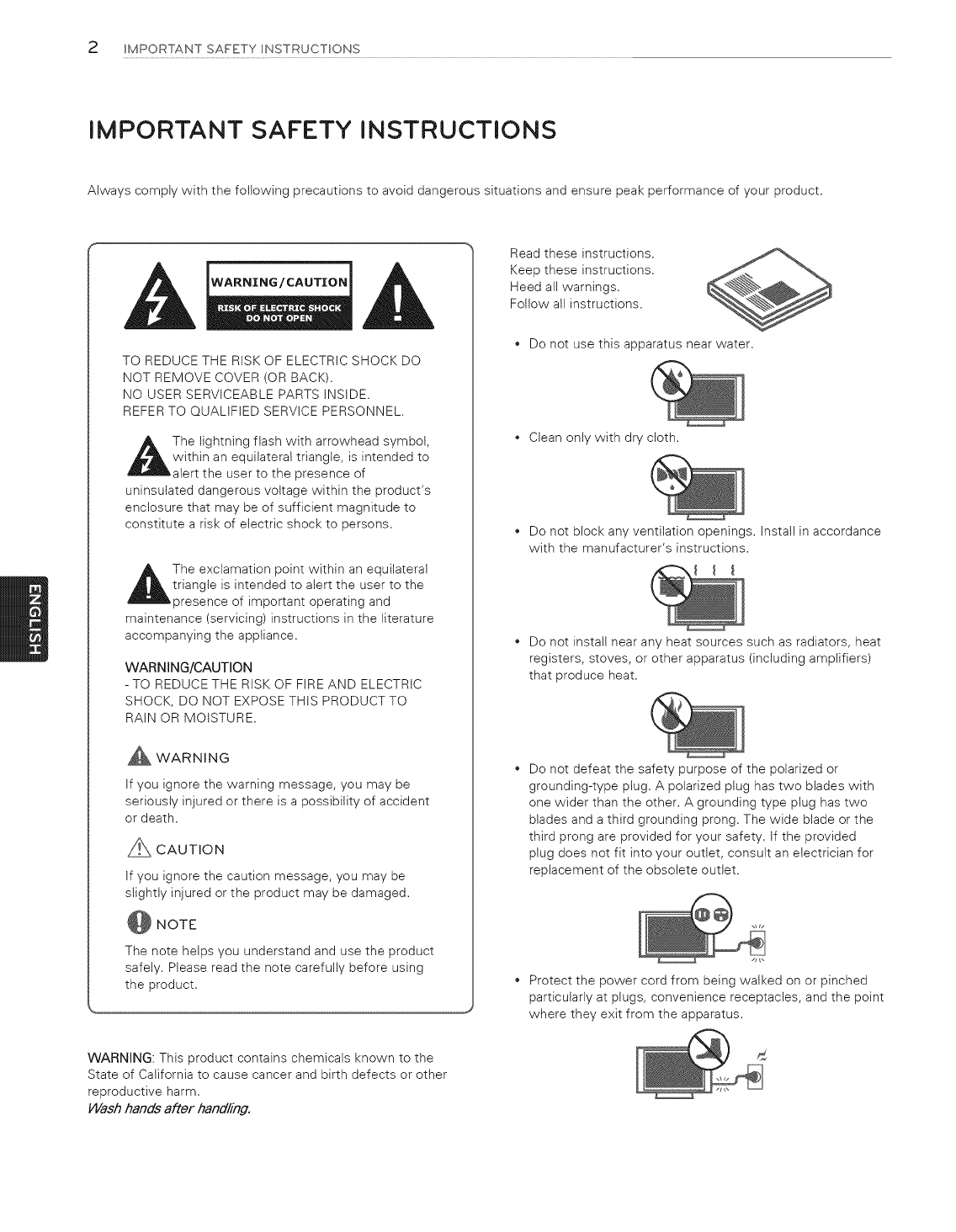
Read these instructions.
Keep these instructions.
Heed all warnings.
Follow all instructions.
Do not use this apparatus near water.
Clean only with dry cloth.
Do not block any ventilation openings. Install in accordance
with the manufacturer's instructions.
Do not install near any heat sources such as radiators, heat
registers, stoves, or other apparatus (including amplifiers)
that produce heat.
Do not defeat the safety purpose of the polarized or
grounding-type piug. A polarized plug has two biades with
one wider than the other. A grounding type piug has two
blades and a third grounding prong. The wide blade or the
third prong are provided for your safety. If the provided
plug does not fit into your outlet, consult an electrician for
replacement of the obsolete outlet.
Protect the power cord from being waiked on or pinched
particularly at plugs, convenience receptacles, and the point
where they exit from the apparatus.
IMPORTANTSAFETYINSTRUCTIONS3
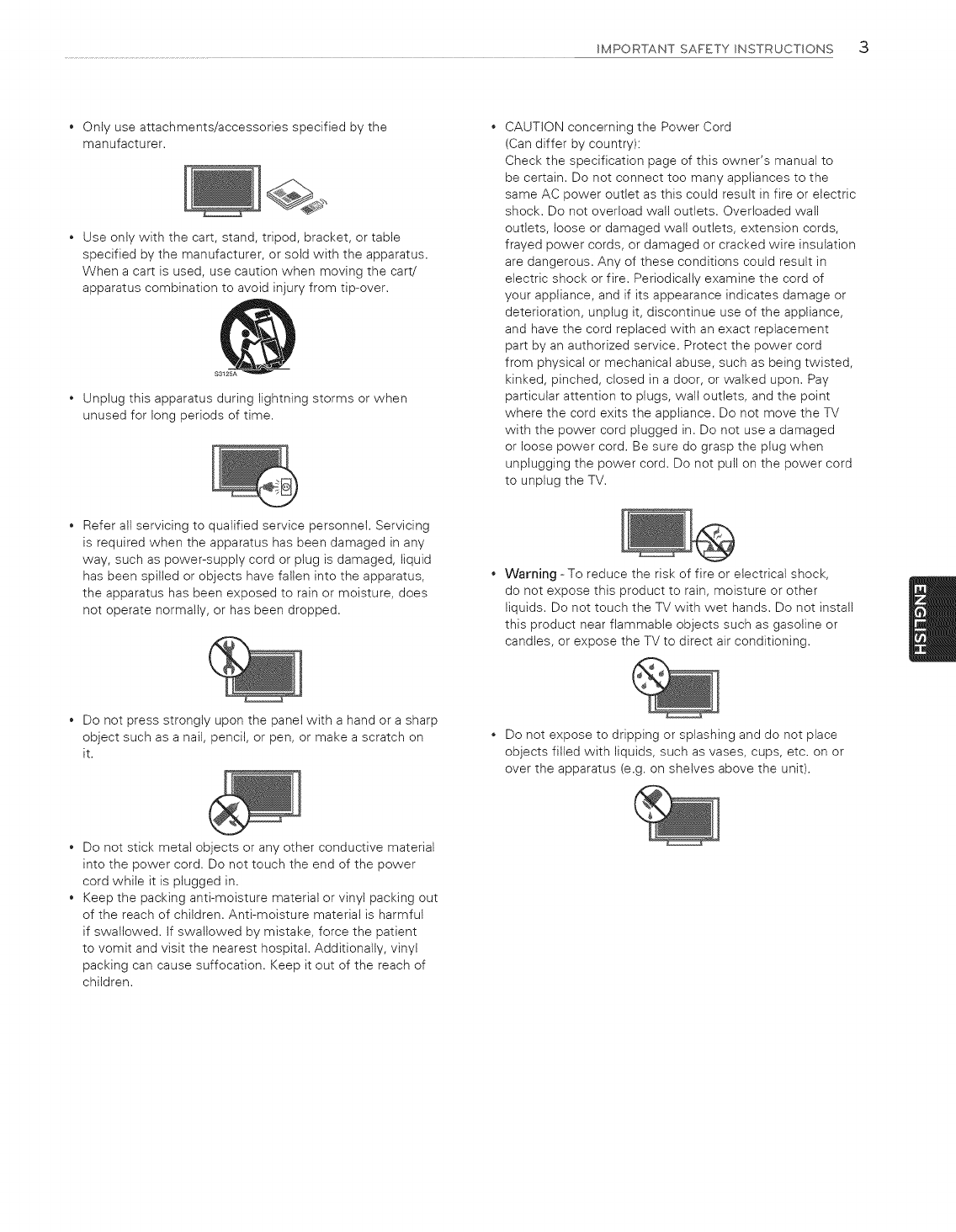
Onlyuseattachments/accessoriesspecifiedbythe
manufacturer.
Useonlywiththecart,stand,tripod,bracket,ortable
specifiedbythemanufacturer,orsoldwiththeapparatus.
Whenacartisused,usecautionwhenmovingthecart/
apparatuscombinationtoavoidinjuryfromtip-over.
Unplugthisapparatusduringlightningstormsorwhen
unusedforlongperiodsoftime.
CAUTIONconcerningthePowerCord
(Candifferbycountry):
Checkthespecificationpageofthisowner'smanualto
becertain.Donotconnecttoomanyappliancestothe
sameACpoweroutletasthiscouldresultinfireorelectric
shock.Donotoverloadwalloutlets.Overloadedwan
outlets,looseordamagedwalloutlets,extensioncords,
frayedpowercords,ordamagedorcrackedwireinsulation
aredangerous.Anyoftheseconditionscouldresultin
electricshockorfire.Periodicallyexaminethecordof
yourappliance,andifitsappearanceindicatesdamageor
deterioration,unplugit,discontinueuseoftheappliance,
andhavethecordreplacedwithanexactreplacement
partbyanauthorizedservice.Protectthepowercord
fromphysicalormechanicalabuse,suchasbeingtwisted,
kinked,pinched,closedinadoor,orwalkedupon.Pay
particularattentiontoplugs,walloutlets,andthepoint
wherethecordexitstheappliance.DonotmovetheTV
withthepowercordpluggedin.Donotuseadamaged
orloosepowercord.Besuredograsptheptugwhen
unpluggingthepowercord.Donotpullonthepowercord
tounplugtheTV.
Referallservicingtoqualifiedservicepersonnel.Servicing
isrequiredwhentheapparatushasbeendamagedinany
way,suchaspower-supplycordorptugisdamaged,liquid
hasbeenspilledorobjectshavefallenintotheapparatus,
theapparatushasbeenexposedtorainormoisture,does
notoperatenormally,orhasbeendropped.
Warning-Toreducetheriskoffireorelectricalshock,
donotexposethisproducttorain,moistureorother
liquids.DonottouchtheTVwithwethands.Donotinstall
thisproductnearflammableobjectssuchasgasolineor
candles,orexposetheTVtodirectairconditioning.
Donotpressstronglyuponthepanelwithahandorasharp
objectsuchasanail,pencil,orpen,ormakeascratchon
it. Do not expose to dripping or splashing and do not place
objects filled with liquids, such as vases, cups, etc. on or
over the apparatus (e.g. on shelves above the unit).
Do not stick metal objects or any other conductive material
into the power cord. Do not touch the end of the power
cord while it is plugged in.
Keep the packing anti-moisture material or vinyl packing out
of the reach of children. Anti-moisture material is harmful
if swallowed. If swallowed by mistake, force the patient
to vomit and visit the nearest hospital. Additionally, vinyl
packing can cause suffocation. Keep it out of the reach of
children.
4IMPORTANT SAFETY INSTRUCTIONS
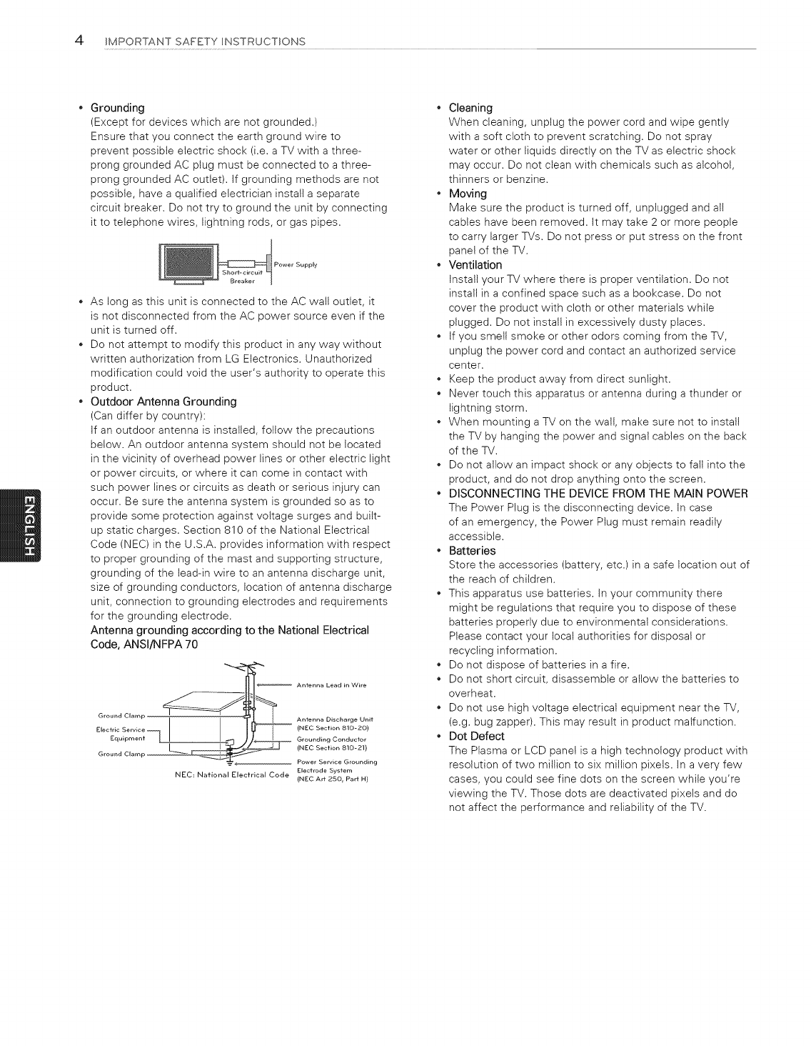
Grounding
(Except for devices which are not grounded.)
Ensure that you connect the earth ground wire to
prevent possible electric shock (i.e. a TV with a three-
prong grounded AC plug must be connected to a three-
prong grounded AC outlet). If grounding methods are not
possible, have a qualified electrician install a separate
circuit breaker. Do not try to ground the unit by connecting
it to telephone wires, lightning rods, or gas pipes.
Supply
As long as this unit is connected to the AC walt outlet, it
is not disconnected from the AC power source even if the
unit is turned off.
Do not attempt to modify this product in any way without
written authorization from LG Electronics. Unauthorized
modification could void the user's authority to operate this
product.
Outdoor Antenna Grounding
(Can differ by country):
If an outdoor antenna is installed, follow the precautions
below. An outdoor antenna system should not be located
in the vicinity of overhead power lines or other electric light
or power circuits, or where it can come in contact with
such power lines or circuits as death or serious injury can
occur. Be sure the antenna system is grounded so as to
provide some protection against voltage surges and built-
up static charges. Section 810 of the National Electrical
Code (NEC) in the U.S.A. provides information with respect
to proper grounding of the mast and supporting structure,
grounding of the lead-in wire to an antenna discharge unit,
size of grounding conductors, location of antenna discharge
unit, connection to grounding electrodes and requirements
for the grounding electrode.
Antenna grounding according to the National Electrical
Code, ANSl/NFPA 70
if:riP _ Ant .... Lead in Wire
(NEC Section 810-20)
_1 C Grounding Conductor
(NEC Section 810-21)
Groun
Power Service Grounding
Electrode System
NEC: National Elecfrical Code (NEC Art 25O r Part H)
• Cleaning
When cleaning, unplug the power cord and wipe gently
with a soft cloth to prevent scratching. Do not spray
water or other liquids directly on the TV as electric shock
may occur. Do not clean with chemicals such as alcohol,
thinners or benzine.
Moving
Make sure the product is turned off, unplugged and alt
cables have been removed. It may take 2 or more people
to carry larger TVs. Do not press or put stress on the front
panel of the TV.
Ventilation
Install your TV where there is proper ventilation. Do not
install in a confined space such as a bookcase. Do not
cover the product with cloth or other materials while
plugged. Do not install in excessively dusty places.
If you smell smoke or other odors coming from the TV,
unplug the power cord and contact an authorized service
center.
Keep the product away from direct sunlight.
Never touch this apparatus or antenna during a thunder or
lightning storm.
When mounting a TV on the wall, make sure not to install
the TV by hanging the power and signal cables on the back
of the TV.
Do not allow an impact shock or any objects to fall into the
product, and do not drop anything onto the screen.
DISCONNECTING THE DEVICE FROM THE MAIN POWER
The Power Plug is the disconnecting device. In case
of an emergency, the Power Plug must remain readily
accessible.
Batteries
Store the accessories (battery, etc.) in a safe location out of
the reach of children.
This apparatus use batteries. In your community there
might be regulations that require you to dispose of these
batteries properly due to environmental considerations.
Please contact your local authorities for disposal or
recycling information.
Do not dispose of batteries in a fire.
Do not short circuit, disassemble or allow the batteries to
overheat.
Do not use high voltage electrical equipment near the TV,
(e.g. bug zapper). This may result in product malfunction.
Dot Defect
The Plasma or LCD panel is a high technology product with
resolution of two million to six million pixets. In a very few
cases, you could see fine dots on the screen while you're
viewing the TV. Those dots are deactivated pixels and do
not affect the performance and reliability of the TV.
IMPORTANTSAFETYINSTRUCTIONS5
GeneratedSound
CrackingnoiseAcrackingnoisethatoccurswhenwatching
orturningofftheTVisgeneratedbyplasticthermal
contractionduetotemperatureandhumidity.Thisnoise
iscommonforproductswherethermaldeformationis
required.
Electricalcircuithumming/panelbuzzingAlowlevelnoise
isgeneratedfromahigh-speedswitchingcircuit,which
suppliesalargeamountofcurrenttooperateaproduct.It
variesdependingupontheproduct.
Thisgeneratedsounddoesnotaffecttheperformanceand
reliabilityoftheproduct.
Takecarenottotouchtheventilationopenings.When
watchingtheTVforalongperiod,theventilationopenings
maybecomehot.Thisdoesnotaffecttheperformanceof
theproductorcausedefectsintheproduct.
Donotinstallthisproductonawallifitcouldbeexposed
tooiloroilmist.Thismaydamagetheproductandcauseit
tofall.
IftheTVfeelscoldtothetouch,theremaybeasmall
flickerwhenitisturnedon.Thisisnormal,thereisnothing
wrongwithTV.Someminutedotdefectsmaybevisible
onthescreen,appearingastinyred,green,orblue
spots.However,theyhavenoadverseeffectontheTV's
performance.AvoidtouchingtheLCDscreenorholding
yourfinger(s)againstitforlongperiodsoftime.Doingso
mayproducesometemporarydistortioneffectsonthe
screen.
...................
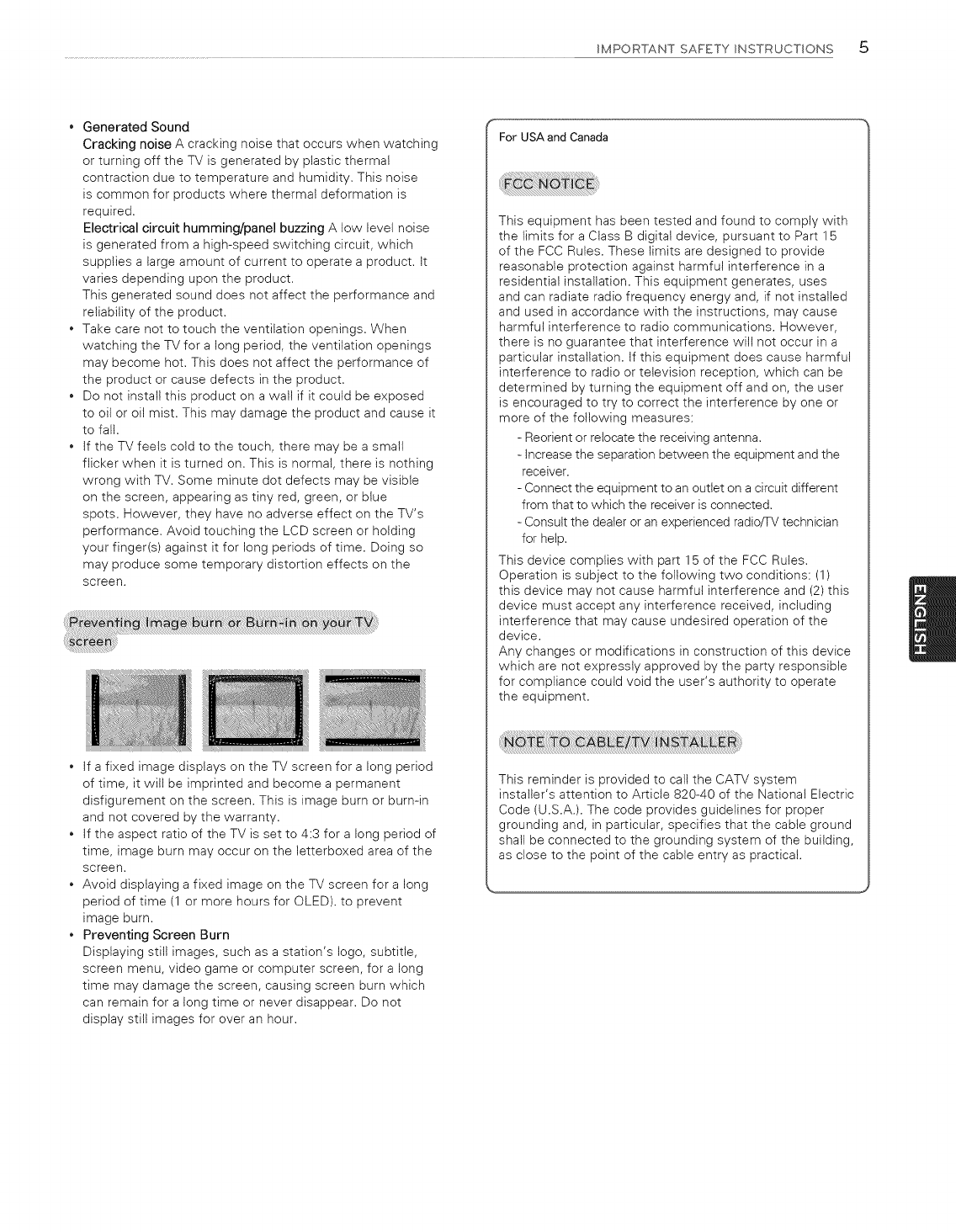
If a fixed image displays on the TV screen for a long period
of time, it will be imprinted and become a permanent
disfigurement on the screen. This is image burn or burn-in
and not covered by the warranty.
If the aspect ratio of the TV is set to 4:3 for a long period of
time, image burn may occur on the letterboxed area of the
screen.
Avoid displaying a fixed image on the TV screen for a long
period of time (1 or more hours for OLED). to prevent
image burn.
Preventing Screen Burn
Displaying still images, such as a station's logo, subtitle,
screen menu, video game or computer screen, for a long
time may damage the screen, causing screen burn which
can remain for a long time or never disappear. Do not
display still images for over an hour.
For USA and Canada
This equipment has been tested and found to comply with
the limits for a Class B digital device, pursuant to Part 15
of the FCC Rules. These limits are designed to provide
reasonable protection against harmful interference in a
residential installation. This equipment generates, uses
and can radiate radio frequency energy and, if not installed
and used in accordance with the instructions, may cause
harmful interference to radio communications. However,
there is no guarantee that interference will not occur in a
particular installation. If this equipment does cause harmful
interference to radio or television reception, which can be
determined by turning the equipment off and on, the user
is encouraged to try to correct the interference by one or
more of the following measures:
- Reorient or relocate the receiving antenna.
- Increase the separation between the equipment and the
receiver.
- Connect the equipment to an outlet on a circuit different
from that to which the receiver is connected.
- Consult the dealer or an experienced radiofTV technician
for help.
This device complies with part 15 of the FCC Rules.
Operation is subject to the following two conditions: (1)
this device may not cause harmful interference and (2) this
device must accept any interference received, including
interference that may cause undesired operation of the
device.
Any changes or modifications in construction of this device
which are not expressly approved by the party responsible
for compliance could void the user's authority to operate
the equipment.
This reminder is provided to call the CATV system
installer's attention to Article 820-40 of the National Electric
Code (U.S.A.). The code provides guidelines for proper
grounding and, in particular, specifies that the cable ground
shall be connected to the grounding system of the building,
as close to the point of the cable entry as practical.
6 IMPORTANTSAFETYINSTRUCTIONS
Viewing 3D Imaging
WARNING
Viewing Time
- When watching 3D contents, take 5 to 15 minute breaks
every hour. Viewing 3D contents for a long period of time
may cause headache, dizziness, fatigue or eye strain.
Some users may experience a seizure or other abnormal
symptoms when they are exposed to a flashing light or
particular pattern from 3D contents.
Do not watch 3D videos if you feet nausea, are pregnant
and/or have a chronic illness such as epilepsy, cardiac
disorder, or blood pressure disease, etc.
3D Contents are not recommended to those who suffer
from stereo blindness or stereo anomaly. Double images or
discomfort in viewing may be experienced.
If you have strabismus (cross-eyed), amblyopia (weak
eyesight) or astigmatism, you may have trouble sensing
depth and easily feet fatigue due to double images. It is
advised to take frequent breaks than the average adult.
If your eyesight varies between your right and left eye,
revise your eyesight prior to watching 3D contents.
CAUTION
Viewing Distance
- Maintain a distance of at least twice the screen diagonal
length when watching 3D contents. If you feet discomfort
in viewing 3D contents, move further away from the TV.
Infants /Children
- Usage/Viewing 3D contents for children under the age of
5 are prohibited.
- Children under the age of 1 0 may overreact and become
overly excited because their vision is in development (for
example: trying to touch the screen or trying to jump into
it. Special monitoring and extra attention is required for
children watching 3D contents.
- Children have greater binocular disparity of 3D
presentations than adults because the distance between
the eyes is shorter than one of adults. Therefore they will
perceive more stereoscopic depth compared to adults for
the same 3D image.
Teenagers
- Teenagers under the age of 19 may be stimulated to light
coming from 3D videos. Advise them not to watch 3D
videos for a long time when they are tired.
Elderly
- The elderly may perceive less of a 3D effect than the
youth. Do not sit closer to the TV than the recommended
distance.
Do not watch 3D contents when you feel fatigue from lack
of sleep, overwork or drinking.
When these symptoms are experienced, stop using/
watching 3D contents and get enough rest until the
symptom subsides.
- Consult your doctor when the symptoms persist.
Symptoms may include headache, eyeball pain, dizziness,
nausea, palpitation, blurriness, discomfort, double image,
visual inconvenience or fatigue.
Make sure to use LG 3D glasses. Otherwise, you may not
be able to view 3D videos properly.
Do not use 3D glasses instead of your normal glasses,
sunglasses or protective goggles.
Using modified 3D glasses may cause eye strain or image
distortion.
Do not keep your 3D glasses in extremely high or low
temperatures. It wilt cause deformation.
The 3D glasses are fragile and are easy to be scratched.
Always use a soft, clean piece of cloth when wiping the
lenses. Do not scratch the lenses of the 3D glasses with
sharp objects or clean/wipe them with chemicals.

LICENSES/OPEN SOURCE SOFTWARE NOTICE INFORMATION 7
LICENSES
Supported licenses may differ by model. For more information about licenses, visit www./g.com.
DOLBY
DIGITAL PLUS
HD
HYn'l| ....
HIGH-DEFINITION MULTIMEDIA INTERFACE
OPEN SOURCE SOFTWARE NOTICE INFORMATION
To obtain the source code under GPL, LGPL, MPL, and other open source licenses, that is contained in this product, please visit http.//
opensource./de, com.
In addition to the source code, all referred license terms, warranty disclaimers and copyright notices are available for download.
LG Electronics will also provide open source code to you on CD-ROM for a charge covering the cost of performing such distribution (such
as the cost of media, shipping, and handling) upon email request to opeiTsoume@/de.com. This offer is valid for three (3) years from
the date on which you purchased the product.
8 TABLE OF CONTENTS
TABLE OF CONTENTS
2IMPORTANT SAFETY INSTRUCTIONS
6 Viewing 3D Imaging
7 LOCENSES
7 OPEN SOURCE SOFTWARE NOTICE
INFORMATION
8 TABLE OF CONTENTS
9 INSTALLATION PROCEDURE
9 ASSEMBLING AND PREPARING
9
11
12
13
14
14
14
15
16
16
18
20
20
21
21
Unpacking
Optional Extras
Parts and Buttons
Using the Joystick Button
Lifting and Moving the TV
Setting Up the TV
- Attaching the AV Cover
- Mounting on a Table
- Tidying Cables
- Mounting on a Wall
- Wall Type Set-up Guide (For 77EG9700)
Using Built-in Camera (For 77EG9700)
- Preparing Built-in Camera
- Name of Parts for the Built-In Camera
- Checking the Camera's Shooting Range
22 MAKING CONNECTIONS
22 Connecting to an Antenna or Cable
23 Connecting to an HD receiver, DVD Player, or VCR
23 - HDMI Connection
25 - DVI to HDMI Connection
2_6 - Connecting to a Mobile Phone
27 - Component Connection
28 - Composite Connection
29 Connecting a PC
29 - HDMI Connection or DVI to HDMI Connection
31 Connecting to an Audio System
31 - Digital Optical Audio Connection
32 Connecting headphones (For 77EG9700)
33 Connecting a USB Device
34 MAGIC REMOTE FUNCTIONS
35 Registering Magic Remote
35 How to use Magic Remote
35 Precautions to Take when Using the Magic Remote
36 USING THE USER GUIDE
37 SPECIFICATIONS
38 EXTERNAL CONTROL DEVICE SETUP
39 MAONTENANCE
39 Cleaning Your TV
39 - Screen, Frame, Cabinet, and Stand
39 - Power Cord
39 TROUBLESHOOTING
l-i[ NOTE
Image shown may differ from your TV,
Your TV's OSD (On Screen Display) may differ slightly
from that shown in this manual.
The available menus and options may differ from the
input source or product model that you are using.
New features may be added to this TV in the future.
INSTALLATIONPROCEDURE/ASSEMBLING AND PREPARING c)
INSTALLATION PROCEDURE
1Open the package and make sure all the accessories are included.
2Connect an external device to the TV set.
3 Make sure the network connection is available.
You can use the TV network functions onty when the network connection is made.
* When the TV is turned on for the first time after being shipped from the factory, initialization of the TV may take approximately one
minute.
ASSEMBLING AND PREPARING
Unpacking
Check your product box for the following items. If there are any missing accessories, contact the local dealer where you purchased
your product. The illustrations in this manual may differ from the actual product and item.
_--j_, CAUTION
• Do not use any unapproved items to ensure the safety and product life span.
• Any damages or injuries by using unapproved items are not covered by the warranty.
• In case of some model, the thin film on screen is a part of TV, So don't take it off.
NOTE
The items supplied with your product may vary depending upon the model.
Product specifications or contents of this manual may be changed without prior notice due to upgrade of product functions.
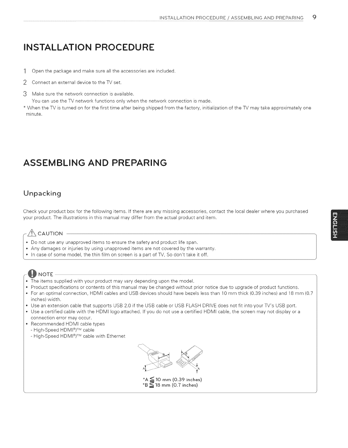
For an optimal connection, HDMI cables and USB devices should have bezels less than 10 mm thick (0.39 inches) and 18 mm (0.7
inches) width.
Use an extension cable that supports USB 2.0 if the USB cable or USB FLASH DRIVE does not fit into your TV's USB port.
Use a certified cable with the HDMI logo attached. If you do not use a certified HDMI cable, the screen may not display or a
connection error may occur.
Recommended HDMt cable types
- High-Speed HDMI®/TM cable
- High-Speed HDMI®/TM cable with Ethernet
_A <_ 10 mm (0.39 inches)
*B _18 mm (0.7 inches)
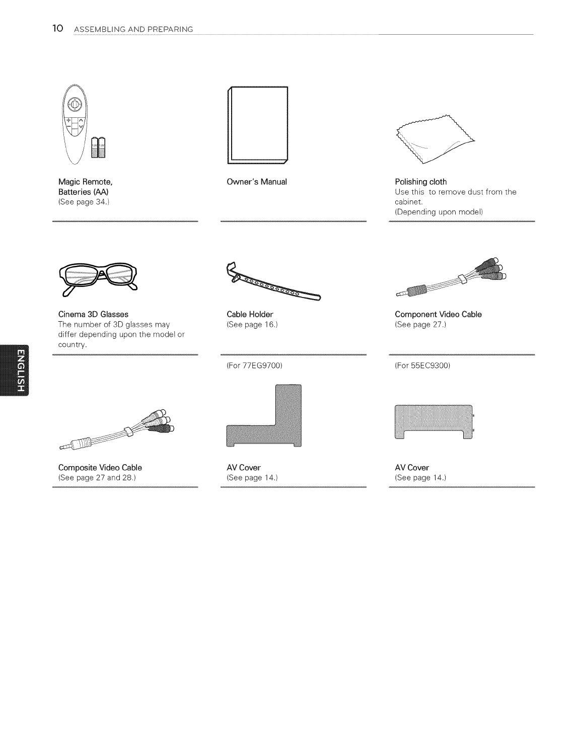
10 ASSEMBLING AND PREPARSNG
Magic Remote,
Batteries (AA)
(See page 34.)
Owner's Manual Polishing cloth
Use this to remove dust from the
cabinet,
(Depending upon model)
Cinema 3D Glasses
The number of 3D glasses may
differ depending upon the model or
country.
Cable Holder
(See page 16.)
(For 77EG9700)
Component Video Cable
(See page 27.)
(For 55EC9300)
Composite Video Cable AV Cover AV Cover
(See page 27 and 28.) (See page 14.) (See page 14.)
ASSEMBLING AND PREPARING 11
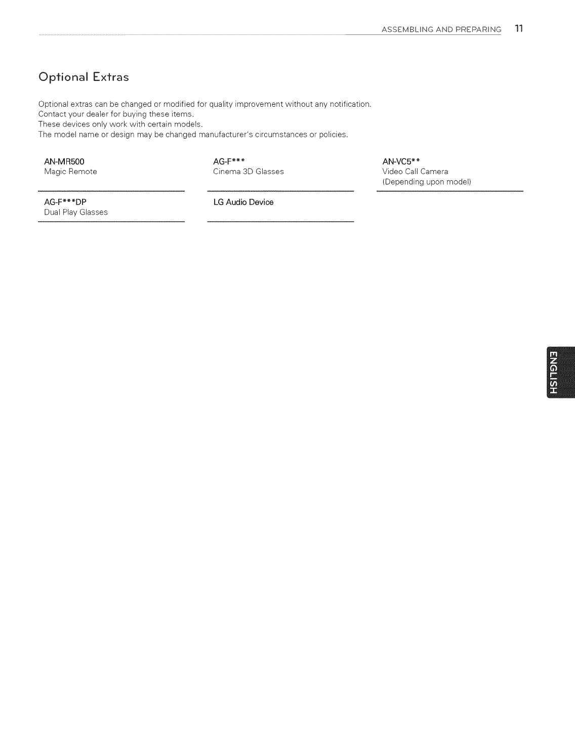
Optional Extras
Optional extras can be changed or modified for quality improvement without any notification.
Contact your dealer for buying these items.
These devices only work with certain models.
The model name or design may be changed manufacturer's circumstances or policies.
AN-MRS00 AG-F***
Magic Remote Cinema 3D Glasses
AG-F***DP LG Audio Device
Dual Play Glasses
AN-VC5**
Video Call Camera
(Depending upon model)
12 ASSEMBLINGANDPREPARSNG
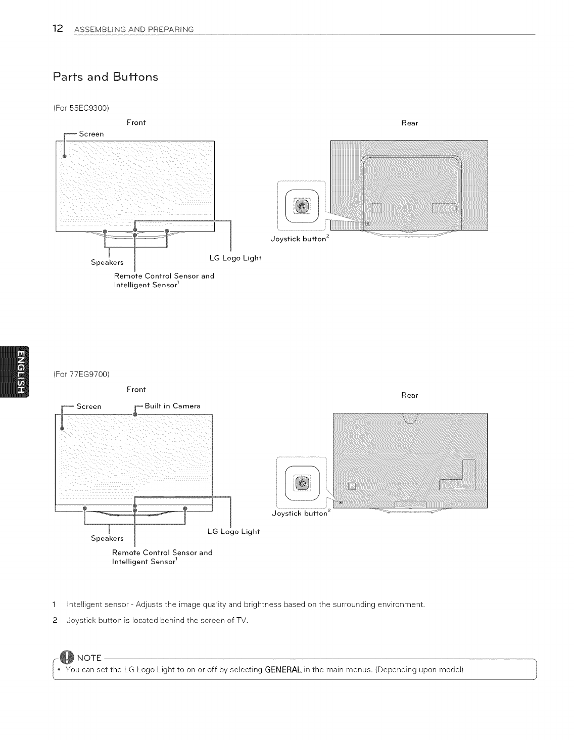
Parts and Buttons
(For 55EC9300
Front
_1_ Screen
Rear
Speakers
]
I
Joystick button 2
LG Logo Light
Remote Control Sensor and
Intelligent Sensor 1
(For 77EG9700)
Front Rear
Speakers
1
LG Logo Light
Remote Control Sensor and
Intelligent Sensor 1
Joystick button 2
1 Intelligent sensor - Adjusts the image quality and brightness based on the surrounding environment.
2 Joystick button is located behind the screen of TV.
,-@ NOTE
• You can set the LG Logo Light to on or off by selecting GENERAL in the main menus. (Depending upon model) }
ASSEMBLING AND PREPARING 13
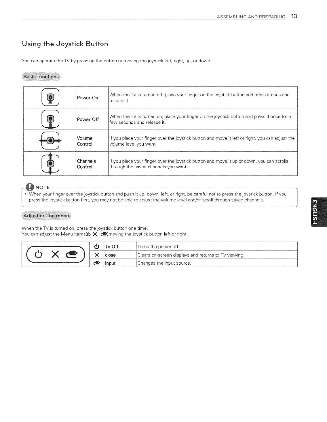
Using the Joystick Button
You can operate the TV by pressing the button or moving the joystick left, right, up, or down.
When the TV is turned off, place your finger on the joystick button and press it once and
Power On release it.
Power Off When the TV is turned on, place your finger on the joystick button and press it once for a
few seconds and release it.
Volume if you place your finger over the joystick button and move it left or right, you can adjust the
Control volume level you want.
_[_ Channels if you place your finger over the joystick button and move it up or down, you can scrolls
Control through the saved channels you want.
@ NOTE
When your finger over the joystick button and push it up, down, left, or right, be careful not to press the joystick button. If you |
press the joystick button first, you may not be able to adjust the volume level and/or scroll through saved channels. J
When the TV is turned on, press the joystick button one time.
You can adjust the Menu items(O, X, _)moving the joystick button left or right.
_lnput
!he POwer Off.
een displays and returns to TV viewing.
input source.
14 ASSEMBLING AND PREPARING
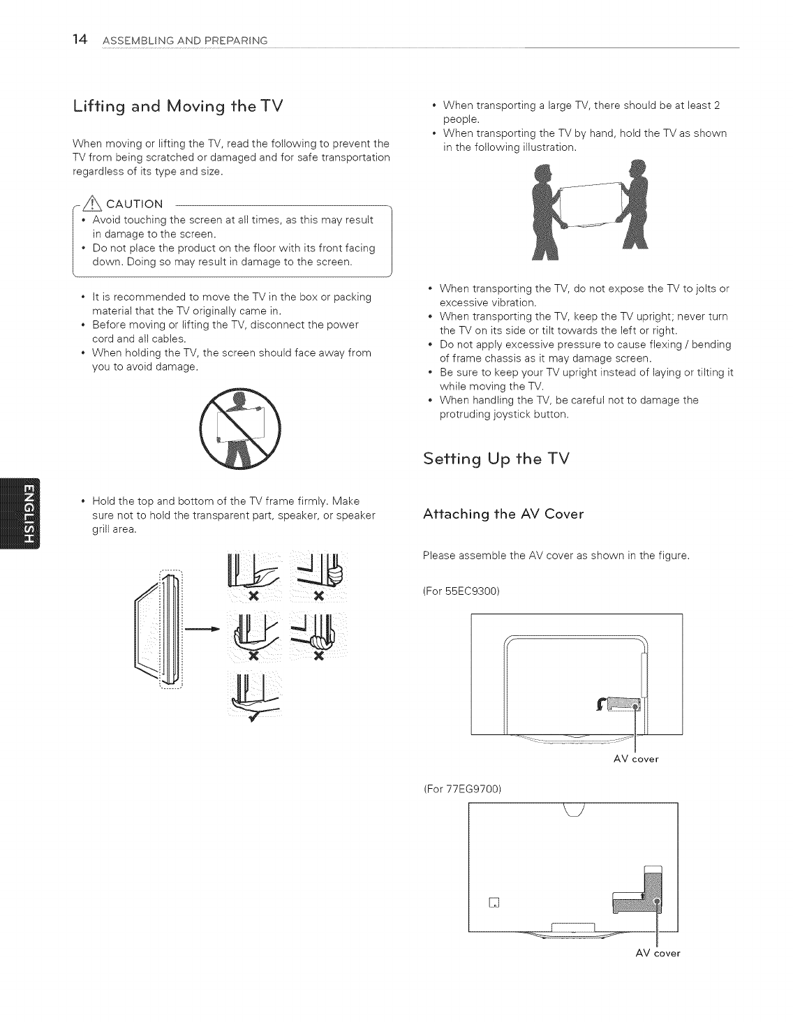
Lifting and Moving theTV
When moving or lifting the TV, read the following to prevent the
TV from being scratched or damaged and for safe transportation
regardless of its type and size.
--_ CAUTION
Avoid touching the screen at all times, as this may result
in damage to the screen.
Do not place the product on the floor with its front facing
down. Doing so may result in damage to the screen.
*it is recommended to move the TV in the box or packing
material that the TV originally came in.
*Before moving or lifting the TV, disconnect the power
cord and alt cables.
*When holding the TV, the screen should face away from
you to avoid damage.
*When transporting a large TV, there should be at least 2
people.
*When transporting the TV by hand, hold the TV as shown
in the following illustration.
*When transporting the TV, do not expose the TV to jolts or
excessive vibration.
*When transporting the TV, keep the TV upright; never turn
the TV on its side or tilt towards the left or right.
*Do not apply excessive pressure to cause flexing /bending
of frame chassis as it may damage screen.
*Be sure to keep your TV upright instead of laying or tilting it
while moving the TV.
*When handling the TV, be careful not to damage the
protruding joystick button.
Setting Up the TV
*Hold the top and bottom of the TV frame firmly. Make
sure not to hold the transparent part, speaker, or speaker
grill area.
LbJ_J
X X
Attaching the AV Cover
Please assemble the AV cover as shown in the figure.
(For 55EC9300)
AV cover
(For 77EG9700)
[]
AM cover
ASSEMBLING AND PREPARING 15
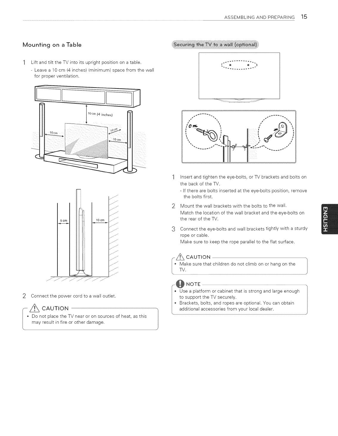
Mounting on a Table
Lift and tilt the TV into its upright position on a table.
- Leave a 10 cm (4 inches) (minimum) space from the wall
for proper ventilation.
ss _
5 cm 10 cm
jJJ
.jJ
I//
jl j
j_J
jJJ
JJ
j/J
j/--
2Connect the power cord to a wall outlet.
_ _Z CAUTION -,}
[ • Do not place the TV near or on sources of heat, as this |
, may result in fire or other damage.
1Insert and tighten the eye-bolts, or TV brackets and bolts on
the back of the TV.
- If there are bolts inserted at the eye-bolts position, remove
the bolts first.
2Mount the wall brackets with the bolts to the walt.
Match the location of the wall bracket and the eye-bolts on
the rear of the TV.
3Connect the eye-bolts and wall brackets tightly with a sturdy
rope or cable.
Make sure to keep the rope parallel to the flat surface.
A CAUTION
Make sure that children do not climb on or hang on the
TV.
_@ NOTE
Use a platform or cabinet that is strong and large enough
to support the TV securely.
Brackets, bolts, and ropes are optional. You can obtain
additional accessories from your local dealer.
16 ASSEMBLINGANDPREPARING
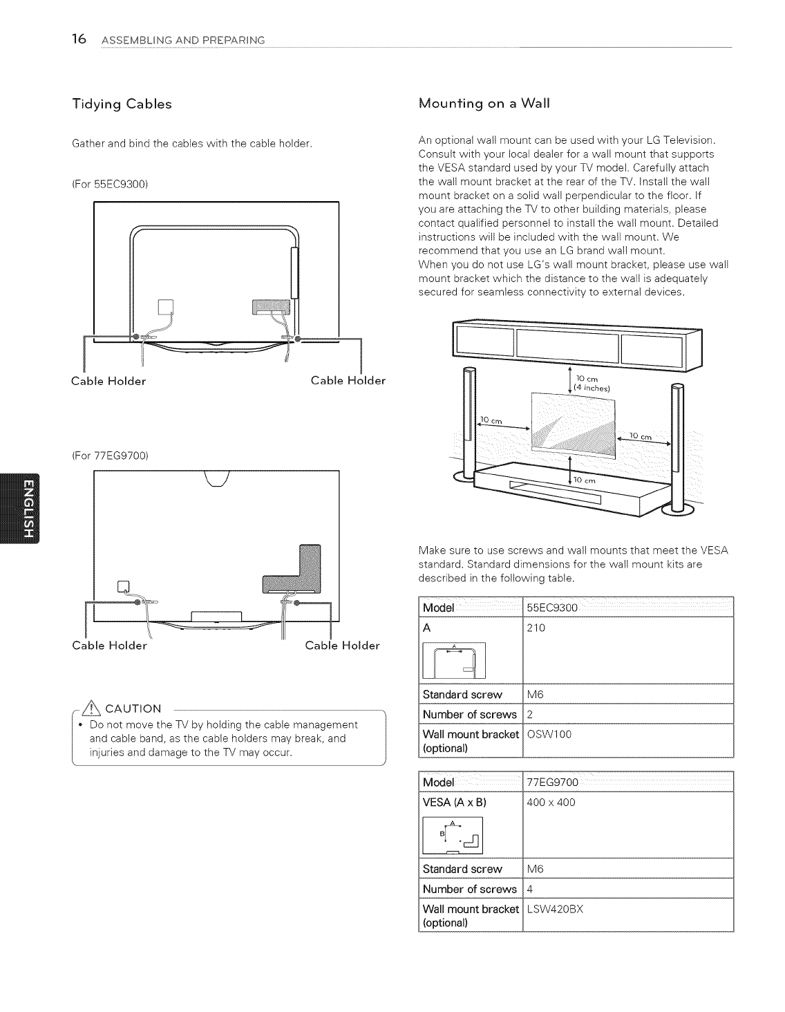
Tidying Cables
Gather and bind the cables with the cable holder.
(For 55EC9300)
Cable Holder Cable Holder
(For 77EG9700)
M/
Cable Holder Cable Holder
--_A CAUTION
Do not move the TV by holding the cable management
and cable band, as the cable holders may break, and J
injuries and damage to the TV may occur.
Mounting on a Wall
An optional walt mount can be used with your LG Television.
Consult with your local dealer for a walt mount that supports
the VESA standard used by your TV model. Carefully attach
the wall mount bracket at the rear of the TV. Install the wall
mount bracket on a solid walt perpendicular to the floor. If
you are attaching the TV to other building materials, please
contact qualified personnel to install the wall mount. Detailed
instructions will be included with the wall mount. We
recommend that you use an LG brand watl mount.
When you do not use LG's walt mount bracket, please use wall
mount bracket which the distance to the wall is adequately
secured for seamless connectivity to external devices.
10 cm
Make sure to use screws and wall mounts that meet the VESA
standard. Standard dimensions for the wall mount kits are
described in the following table.
Model 55EC9300
A 210
Standard screw M6
Number of screws 2
Wall mount bracket OSW100
(optional)
VESA (A x B)
A
Standard screw
Number of screws
Wall mount bracket
(optional)
77EG9700
400 x 400
M6
4
LSW420BX
ASSEMBLING AND PREPARING 17
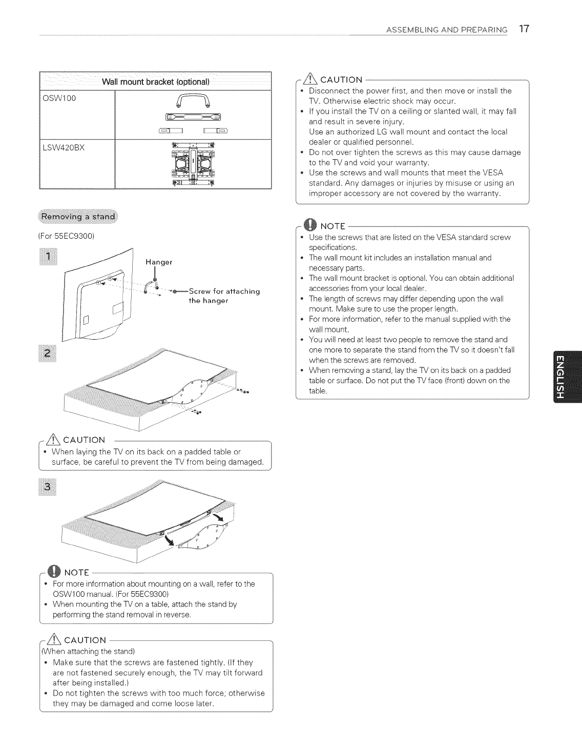
OSW1 O0
LSW420BX
y=%
.._ CAUTION
• Disconnect the power first, and then move or install the
TV. Otherwise electric shock may occur.
If you install the TV on a ceiling or slanted wall, it may fall
and result in severe injury.
Use an authorized LG wall mount and contact the local
dealer or qualified personnel.
Do not over tighten the screws as this may cause damage
to the TV and void your warranty.
Use the screws and walt mounts that meet the VESA
standard. Any damages or injuries by misuse or using an
improper accessory are not covered by the warranty.
(For 55EC9300)
Hanger
for attaching
the hanger
_ @ NOTE
Use the screws that are listed on the VESA standard screw
specifications.
The wall mount kit includes an installation manual and
necessary parts.
The wall mount bracket is optional. You can obtain additional
accessories from your local dealer.
The length of screws may differ depending upon the wall
mount. Make sure to use the proper length.
For more information, refer to the manual supplied with the
wall mount.
You will need at least two people to remove the stand and
one more to separate the stand from the TV so it doesn't fall
when the screws are removed.
When removing a stand, lay the TV on its back on a padded
table or surface. Do not put the TV face (front) down on the
table.
_i@ NOTE
For more information about mounting on a wall, refer to the
OSW100 manual. (For 55EC9300)
When mounting the TV on a table, attach the stand by
performing the stand removal in reverse.
iA CAUTION
hen attaching the stand)
Make sure that the screws are fastened tightly. (If they
are not fastened securely enough, the TV may tilt forward
after being installed.)
Do not tighten the screws with too much force; otherwise
they may be damaged and come loose later.
]8 ASSEMBLING AND PREPARING
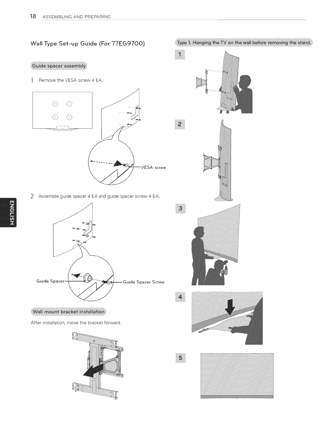
Wall Type Set-up Guide (For 77EG9700)
1Remove the VESA screw 4 EA.
screw
2Assemble guide spacer 4 EA and guide spacer screw 4 EA.
Guide S Spacer Screw
After installation, move the bracket forward.
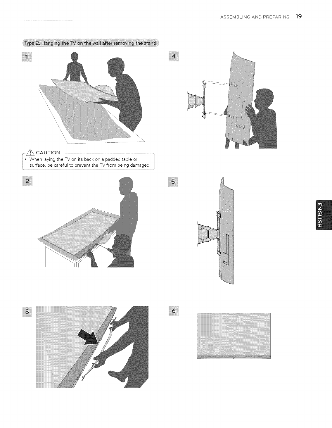
ASSEMBLING AND PREPARING 19
\\
\\\\\\\\
\\
oAuT oN
When laying the TV on its back on a padded table or ]
surface, be careful to prevent the TV from being damaged.
20 ASSEMBLING AND PREPARING
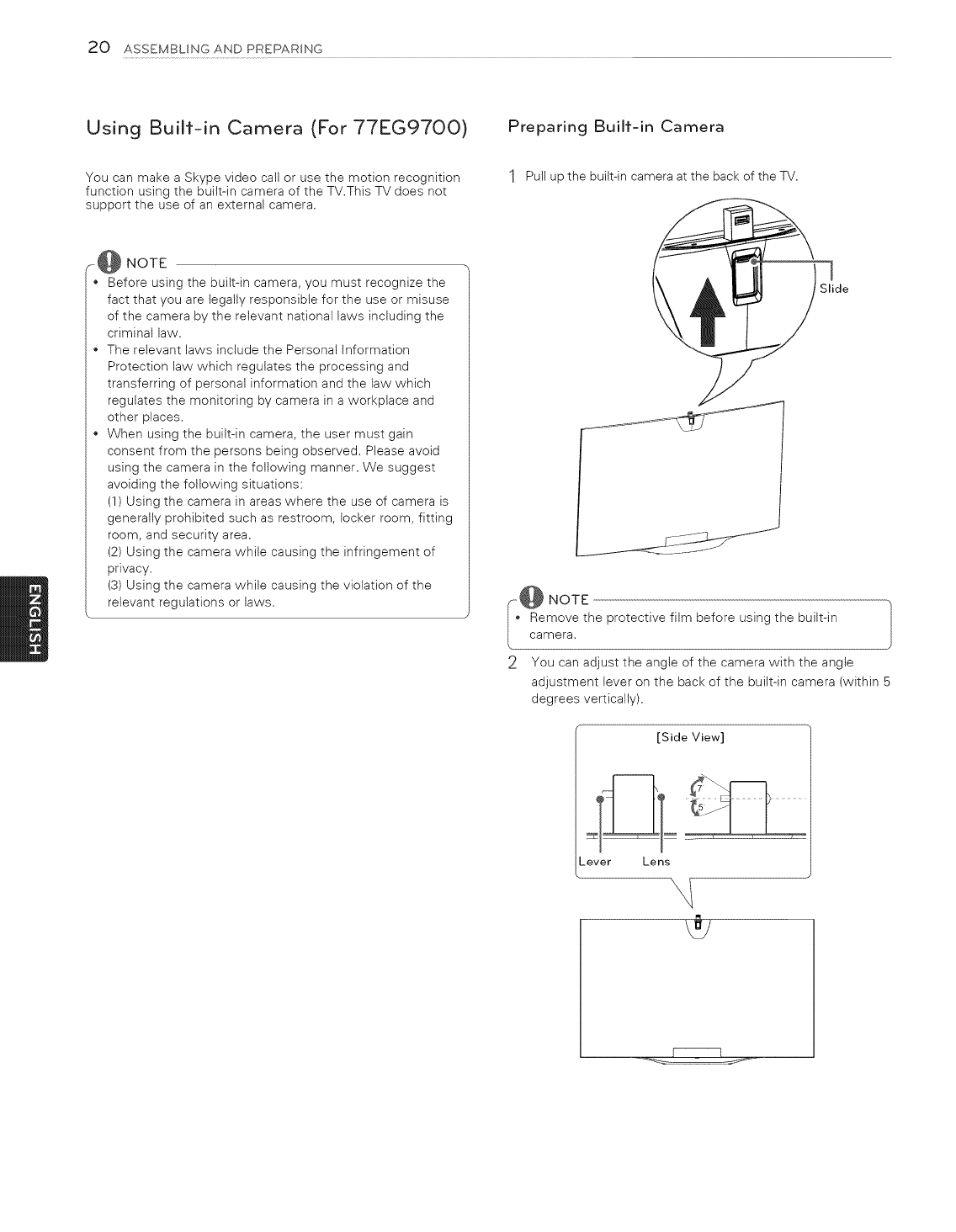
Using Built-in Camera (For 77EG97OO)
You can make a Skype video call or use the motion recognition
function using the built-in camera of the TV.This TV does not
support the use of an external camera.
Preparing Built-in Camera
1Pull upthe built-in cameraat the backof the TV.
_@ NOTE
*Before using the built-in camera, you must recognize the
fact that you are legally responsible for the use or misuse
of the camera by the relevant national laws including the
criminal law.
*The relevant laws include the Personal Information
Protection law which regulates the processing and
transferring of personal information and the law which
regulates the monitoring by camera in a workplace and
other places.
*When using the built-in camera, the user must gain
consent from the persons being observed. Please avoid
using the camera in the following manner. We suggest
avoiding the following situations:
(1) Using the camera in areas where the use of camera is
generally prohibited such as restroom, locker room, fitting
room, and security area.
(2) Using the camera while causing the infringement of
privacy.
(3) Using the camera while causing the violation of the
relevant regulations or laws.
I
Slide
J
--_@ NOTE
Remove the protective film before using the built-in Jcamera.
2You can adjust the angle of the camera with the angle
adjustment lever on the back of the built-in camera (within 5
degrees vertically).
[Side View]
_ever Lens
ASSEMBLING AND PREPARING 21
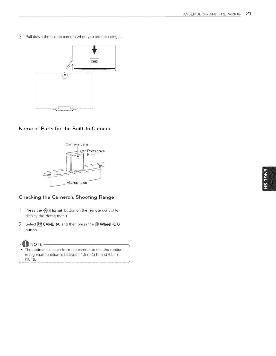
Pull down the built-in camera when you are not using it.
Name of Parrs for fhe Builf-ln Camera
Camera Lens
Film
Microphone
Checking fhe Camera's Shoofing Range
1Press the _ (Home) button on the remote control to
display the Home menu.
2Select [] CAMERA and then press the 0 Wheel (OK)
button.
@ NOTE
The optimal distance from the camera to use the motion
recognition function is between 1.5 m (5 ft) and 4.5 m
(I 5 ft).
22 MAKING CONNECTIONS
MAKING CONNECTIONS
Image shown may differ from your TV.
You can connect various external devices to the TV. Supported external devices are: HD receivers, DVD players, VCRs, audio systems,
USB storage devices, PC, gaming devices, and other external devices. For more information on external device's connection, refer to
the manual provided with each device.
(_,@ NOTE
I' If you record a TV program on a DVD recorder or VCR, make sure to connect the TV signal input cable to the TV through a DVD
recorder or VCR. For more information of recording, refer to the manual provided with the connected device.
I • The external device connections shown may differ slightly from illustrations in this manual.
I • Connect external devices to the TV regardless of the order of the TV port.
I • If you connect a gaming device to the TV, use the cable supplied with the gaming device.
• Refer to the external equipment's manual for operating instructions.
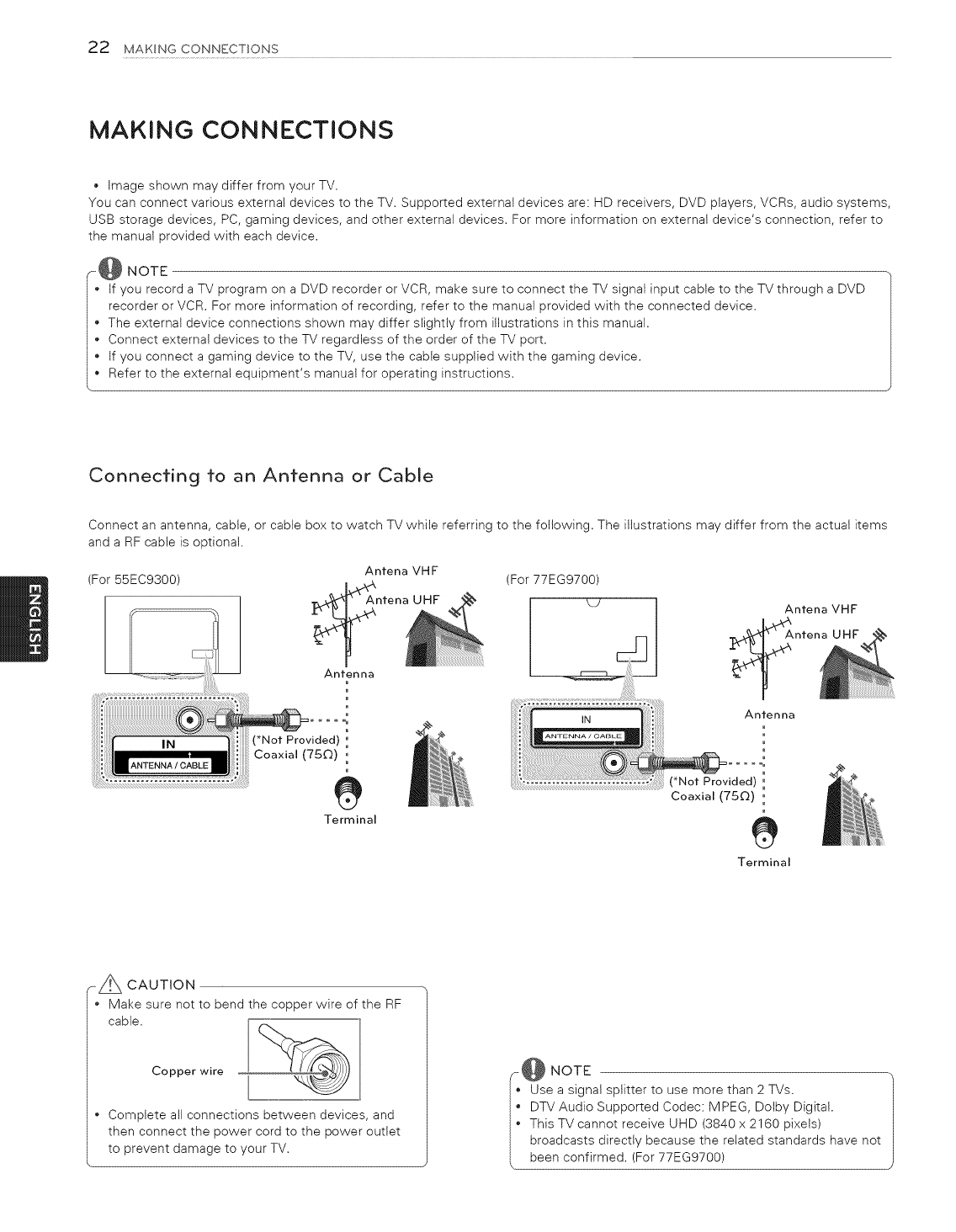
Connecting to an Antenna or Calole
Connect an antenna, cable, or cable box to watch TV while referring to the following. The illustrations may differ from the actual items
and a RF cable is optional.
(For 55EC9300) Antena VHF (For 77EG9700)
ntena UHF
Antenna
Antenna
m
Terminal
(*Not Provided) '
Coaxial (750) 0
e
Terminal
r- A CAUTION
Make sure not to bend the copper wire of the RF
cable.
Copper wire
• Complete all connections between devices, and
then connect the power cord to the power outlet
to prevent damage to your TV.
ii NOTE
Use a signal splitter to use more than 2 TVs.
DTV Audio Supported Codec: MPEG, Dolby Digital.
I' This TV cannot receive UHD (3840 x 2160 pixets)
broadcasts directly because the related standards have not
MAKING CONNECTIONS 23
Connecting to an HD receiver, DVD Player, or VCR
Connect an HD receiver, DVD Player, or VCR to the TV and select an appropriate input mode.
NOTE
(For 77EG9700)
•HDMI specifications may be different for each input port, so make sure to check the device specifications before connecting.
• The HDMI IN 3 port is especially suitable for the specifications to enjoy UHD Video (4:4:4, 4:2:2) of 4K @60 Hz. However, video
or audio may not be supported depending upon the specifications of the external equipment. In that case, use any other HDMI
• IN port.
Contact customer service for more information on the HDMI specifications of each input port.
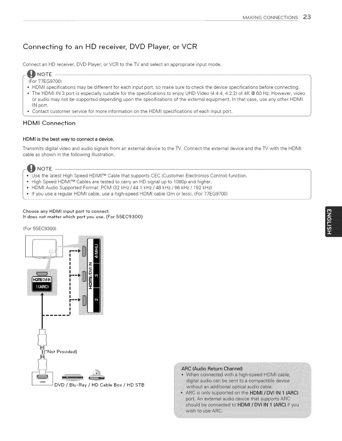
HDMI Connecfion
HDMI is the best way to connect a device.
Transmits digital video and audio signals from an external device to the TV. Connect the external device and the TV with the HDMI
cabte as shown in the following illustration.
NOTE
•Use the latest High Speed HDMt TM Cable that supports CEC (Customer Electronics Control) function.
High Speed HDMI TM Cables are tested to carry an HD signal up to 1080p and higher.
HDMI Audio Supported Format: PCM (32 kHz/44.1 kHz/48 kHz/96 kHz/192 kHz)
if you use a reguiar HDMI cable, use a high-speed HDMI cable (3m or less). (For 77EG9700)
Choose any HDMI input port to connect.
It does not matter which port you use, (For 55EC93OO)
(For 55EC9300)
Not Provided)
DVD /Blu-Ray /HD Cable Box /HD STB
24 MAKING CONNECTIONS
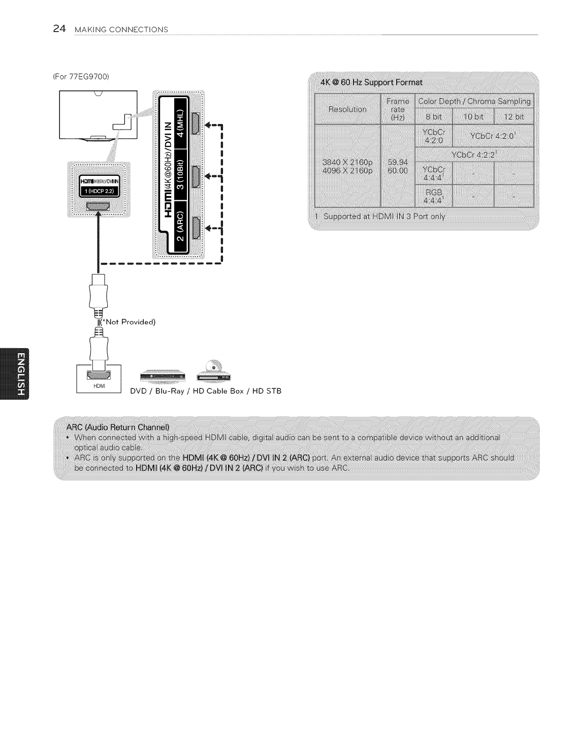
(For 77EG9700)
|
|
I
|
! '
|
|
_(*Not Provided)
DVD /Blu-Ray /HD Cable Box /HD STB
MAKINGCONNECTIONS25
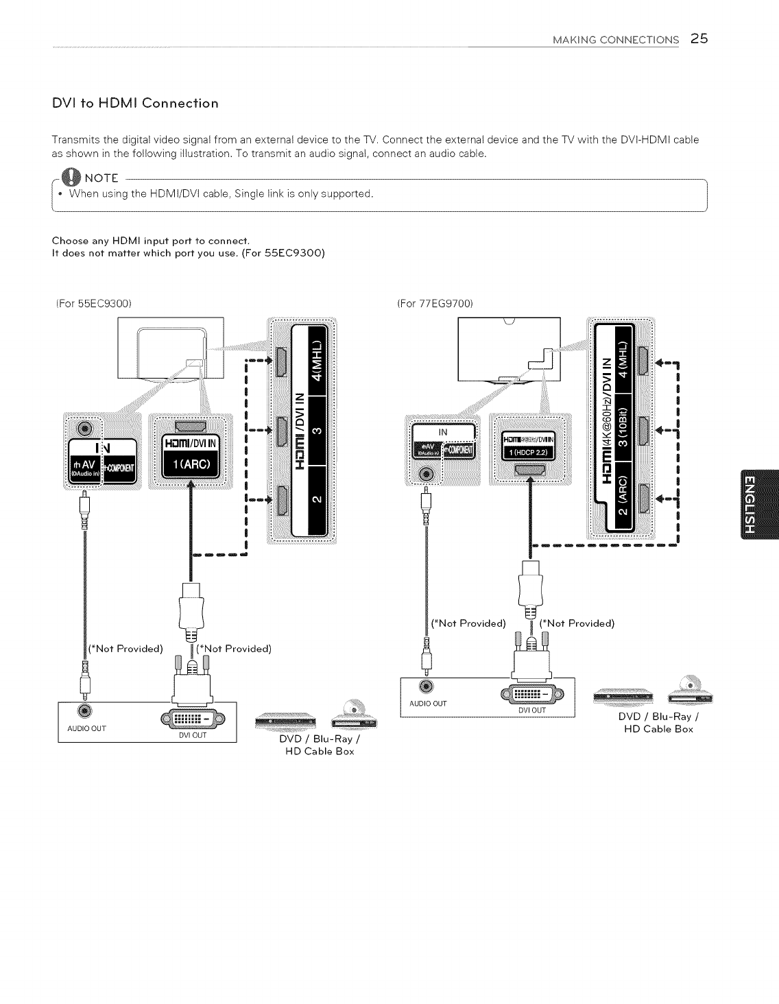
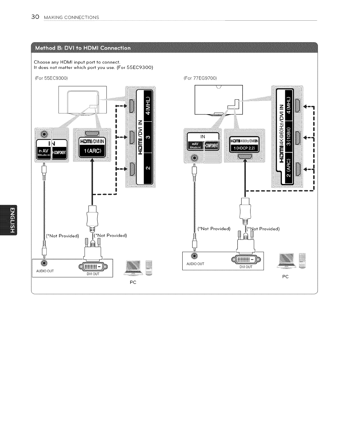
DVI to HDMI Connection
Transmits the digital video signal from an external device to the TV. Connect the external device and the TV with the DVI-HDMI cable
as shown in the following illustration. To transmit an audio signal, connect an audio cable.
I.:@NoTE
When using the HDMI/DVI cable, Single link is only supported.
Choose any HDMI input port to connect.
It does not matter which port you use, (For 55EC93OO)
(For 55EC9300) (For 77EG9700)
|
I
mmm_J
(*Not Provided) _ _(Not Provided)
@
AUDIO OUT
DVIOUTJ DVD/ Blu-Ray/
HD Cable Box
!
|
!
!
!
!
!
!
!
!
!
!
(*Not Provided) _ (*Not Provided)
AU UT
Blu-Ray /
HD Cable Box
26 MAKINGCONNECTIONS
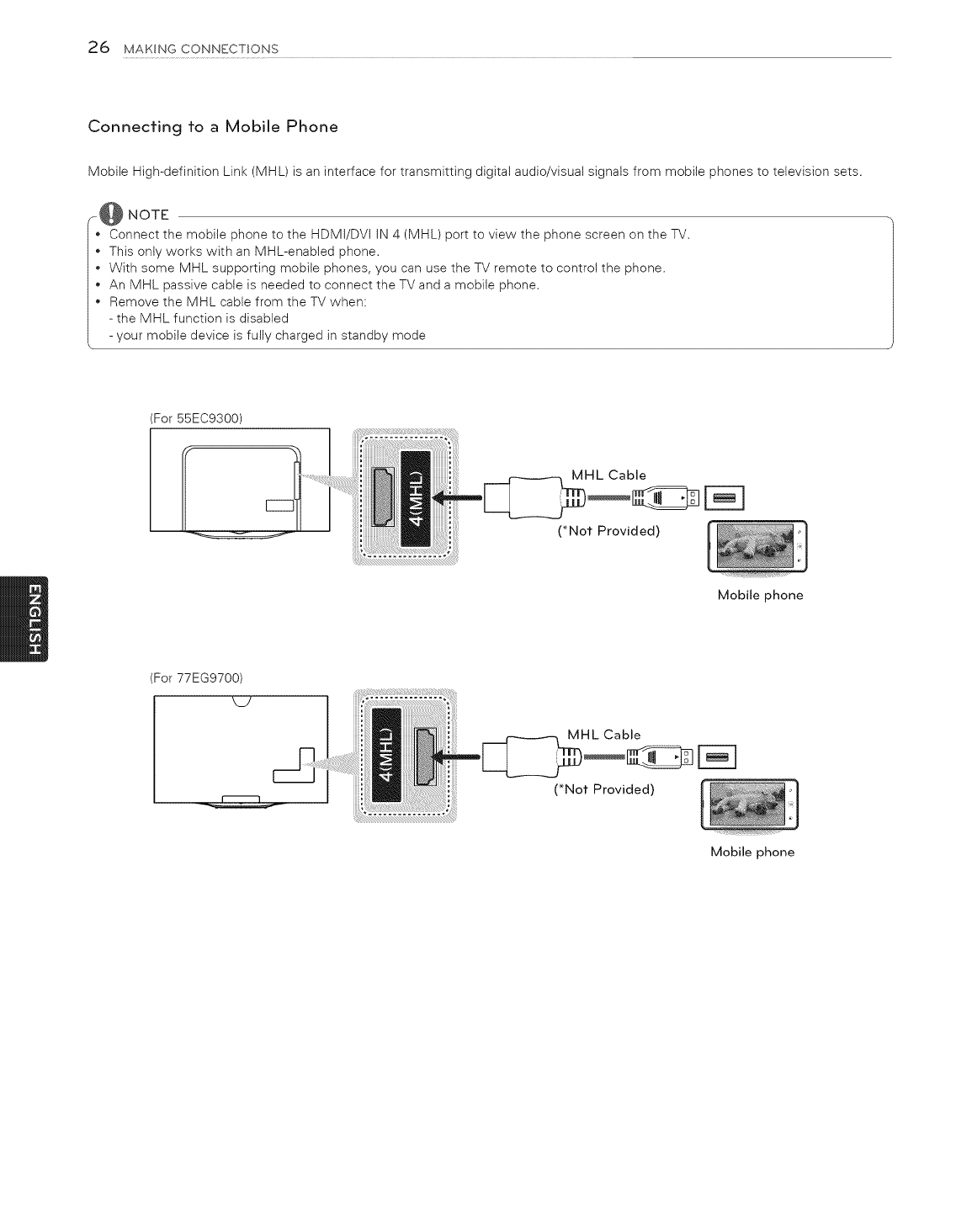
Connecting to a Mobile Phone
Mobile High-definition Link (MHL) is an interface for transmitting digital audio/visual signals from mobile phones to television sets.
r@ NOTE
*Connect the mobile phone to the HDMi/DVi iN 4 (MHL) port to view the phone screen on the TV.
*This only works with an MHL-enabled phone.
+ With some MHL supporting mobile phones, you can use the TV remote to control the phone.
An MHL passive cable is needed to connect the TV and a mobile phone.
Remove the MHL cable from the TV when:
- the MHL function is disabled
- your mobile device is fully charged in standby mode
:or 55EC9300)
:or 77EG9700)
Mobile phone
Mobile phone
MAKINGCONNECTIONS2"7
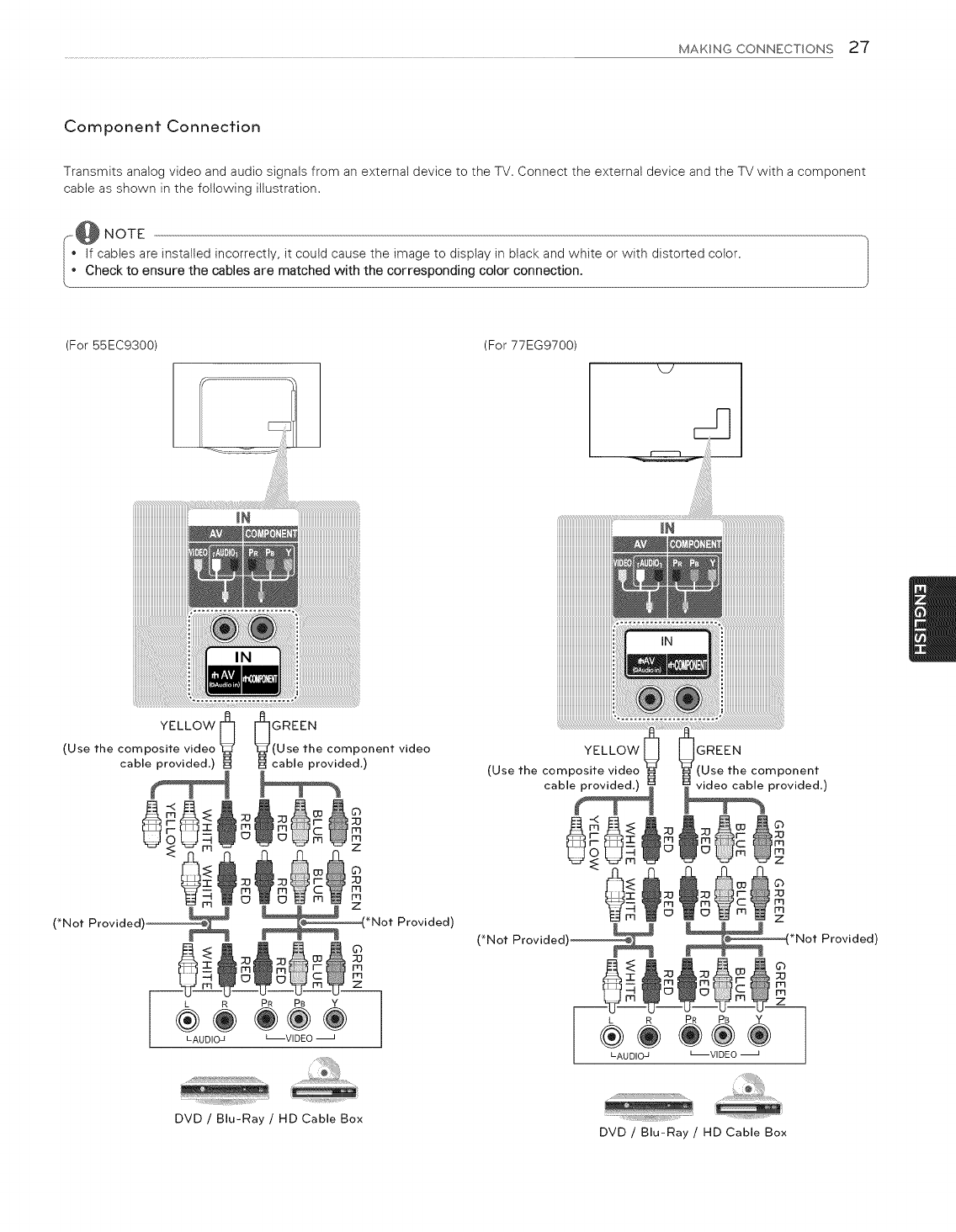
Component Connection
Transmits analog video and audio signals from an external device to the TV. Connect the external device and the TV with a component
cabte as shown in the following illustration.
--:@ NOTE
if cables are installed incorrectly, it could cause the image to display in black and white or with distorted color.
Check to ensure the cables are matched with the corresponding color connection.
(For 55EC9300) (For 77EG9700)
_Y
YELLOW [_
(Use the composite video
cable provided.)
0
(*Not Provided'
L R PR PB Y
LAUDIO_ _VIDEO
GREEN
(Use the component video
cable provided.)
©
;O
m
m
z
Provided)
YELLOW
(Use the composite video
cable provided.)
GREEN
(Use the component
video cable provided.)
Z
*Not Provided)
©
rq
m
z
L R PR PB Y
LAUDIOJ L--VIDEO
.....!;_!iiiii}i_,
DVD /Blu-Ray /HD Cable Box .... .......
DVD /Blu-Ray /HD Cable Box
28 MAKINGCONNECTIONS
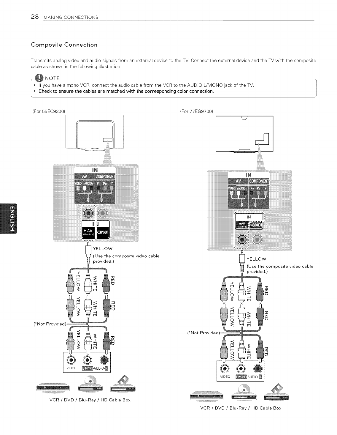
Composite Connection
Transmits analog video and audio signals from an external device to the TV. Connect the external device and the TV with the composite
cable as shown in the following illustration.
_o@ NOTE
, f you have a mono VCR, connect the audio cable from the VCR to the AUDIO L/MONO jack of the TV.
o Check to ensure the cables are matched with the corresponding color connection.
(For55EC9300
iiiiiiiiiiiiiiiiiiiiiiiiiiiiiiiiiiiiiiiiiiiiii_i_i_!
_iiiiiiiiiiiiiiiii!i_
(For 77EG9700)
MY
iiiiiiiiiiiiii_
_] YELLOW
"_ (Use the composite video cable
provided.)
(*Not Provided
38
VCR /DVD /Blu-Ray /HD Cable Box
_ YELLOW
(Use the composite video cable
ed.)
(*Not Provided)_
®®O
WDEO_uDIo_
VCR /DVD /Blu-Ray /HD Cable Box
MAKING CONNECTIONS 29
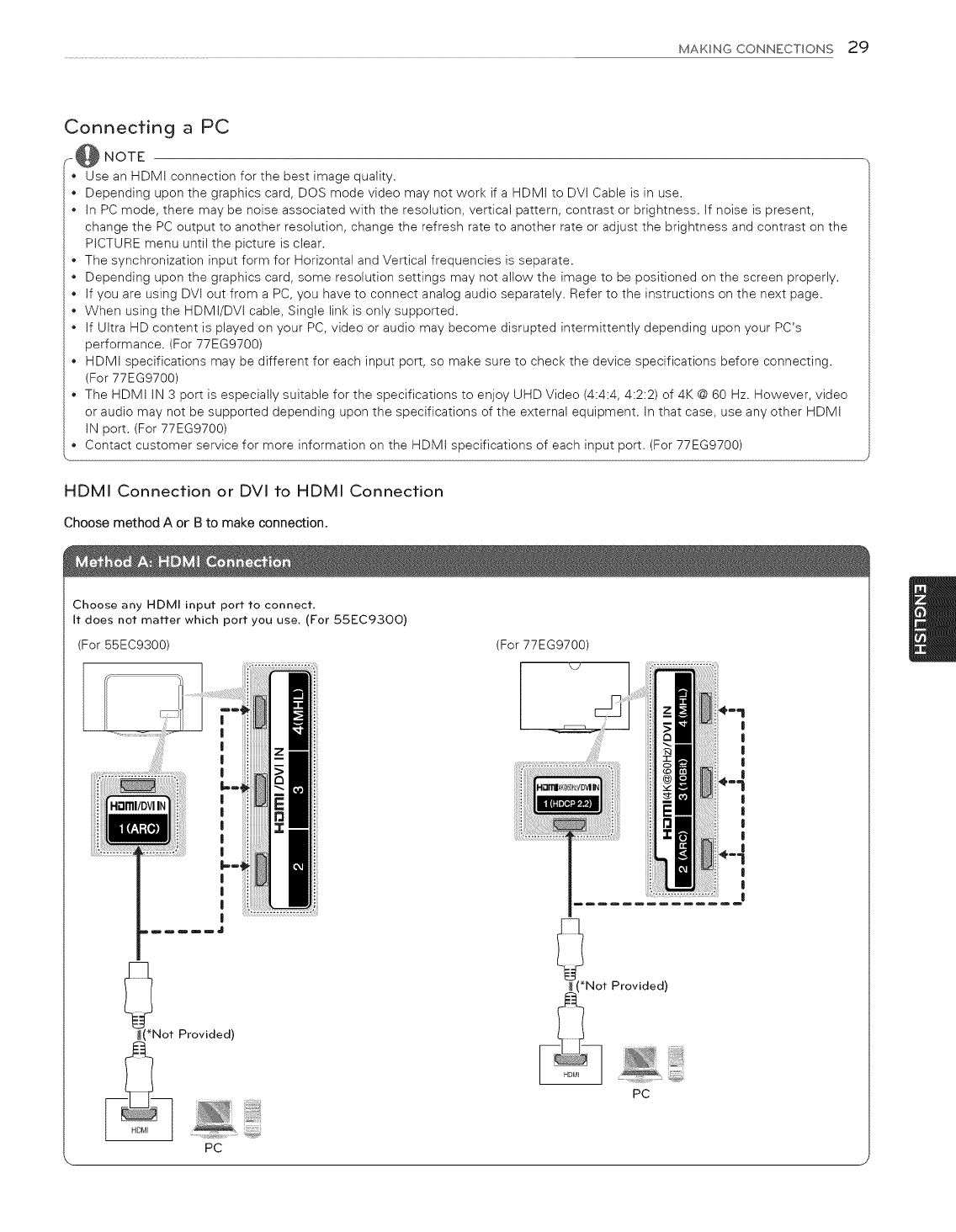
Connecting a PC
_-@ NOTE
Use an HDMI connection for the best image quality.
*Depending upon the graphics card, DOS mode video may not work if a HDMI to DVI Cable is in use.
*In PC mode, there may be noise associated with the resolution, vertical pattern, contrast or brightness. If noise is present,
change the PC output to another resolution, change the refresh rate to another rate or adjust the brightness and contrast on the
PICTURE menu until the picture is clear.
*The synchronization input form for Horizontal and Vertical frequencies is separate.
*Depending upon the graphics card, some resolution settings may not allow the image to be positioned on the screen properly.
*If you are using DVI out from a PC, you have to connect analog audio separately. Refer to the instructions on the next page.
*When using the HDMI/DVI cable, Single link is only supported.
*If Ultra HD content is played on your PC, video or audio may become disrupted intermittently depending upon your PC's
performance. (For 77EG9700)
*HDMI specifications may be different for each input port, so make sure to check the device specifications before connecting.
(For 77EG9700)
The HDMI IN 3 port is especially suitable for the specifications to enjoy UHD Video (4:4:4, 4:2:2) of 4K @ 60 Hz. However, video
or audio may not be supported depending upon the specifications of the external equipment. In that case, use any other HDMI
IN port. (For 77EG9700)
o Contact customer service for more information on the HDMI specifications of each input port. (For 77EG9700)
HDMI Connection or DVI to HDMI Connection
Choose method A or B to make connection.
Choose any HDMI input port to connect,
It does not matter which port you use. (For 55EC93OO)
(For 55EC9300) (For 77EG9700)
:i!i!i!il |
|
I
|
I
!
*Not Provided)
PC
Not Provided)
PC
l
I
|
|
|
l
I
I
|
|
I
|
30 MAKING CONNECTIONS
Choose any HDMI input port to connect.
It does not matter which port you use, (For 55EC93OO)
(For 55EC9300)
|
|
|
|
)_*N°t Provided) _*Not Provided)
U
PC
(For 77EG9700)
(*Not Provided)
6
AUDIO OUT
0
t Provided)
PC
MAKING CONNECTIONS 31
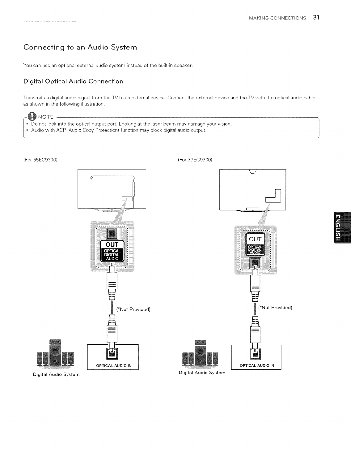
Connecting to an Audio System
You can use an optional external audio system instead of the built-in speaker.
Digital Optical Audio Connection
Transmits a digital audio signal from the TV to an external device. Connect the external device and the TV with the optical audio cable
as shown in the following illustration.
--L@N°TE
Do not look into the optical output port. Looking at the laser beam may damage your vision.
Audio with ACP (Audio Copy Protection) function may block digital audio output.
(For 55EC9300) (For 77EG9700)
.................................................i!!!!!!!!!!!!!i_i¸¸..........................
i (_Not Provided)
OPTICAL AUDIO IN
I (_Not Provided)
OPTICAL AUDIO IN
Digital Audio System Digital Audio System
32 MAKING CONNECTIONS
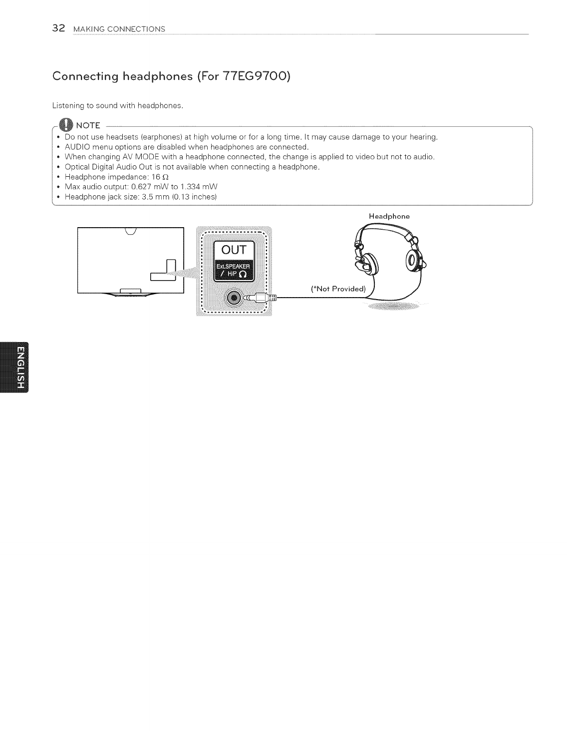
Connecting headphones (For 77EG97OO)
Listening to sound with headphones.
_@ NOTE
Do not use headsets (earphones) at high volume or for a long time. It may cause damage to your hearing.
AUDIO menu options are disabled when headphones are connected.
When changing AV MODE with a headphone connected, the change is applied to video but not to audio.
Optical Digital Audio Out is not available when connecting a headphone.
Headphone impedance: 16 _
• Max audio output: 0.627 mW to 1.334 mW
Headphone jack size: 3.5 mm (0.13 inches)
Headphone
(_Not Provid_
MAKING CONNECTIONS 33
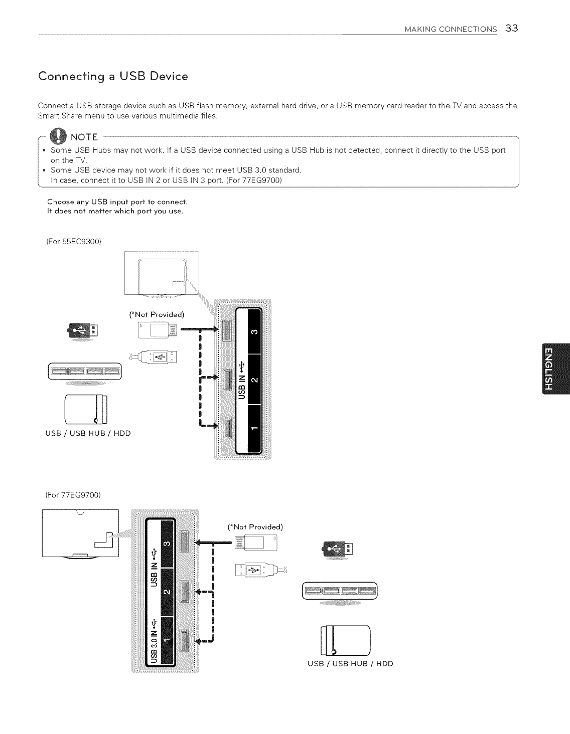
Connecting a USB Device
Connect a USB storage device such as USB flash memory, external hard drive, or a USB memory card reader to the TV and access the
Smart Share menu to use various multimedia files.
Some USB Hubs may not work. If a USB device connected using a USB Hub is not detected, connect it directly to the USB port
on the TV.
Some USB device may not work if it does not meet USB 3.0 standard.
In case, connect it to USB IN 2 or USB IN 3 port. (For 77EG9700)
Choose any USB input port to connect.
It does not matter which port you use,
(For 55EC9300)
(_Not Provided)
USB/USB HUB/ HDD
|
|
|
|
|
|
(For 77EG9700)
(_Not Provided)
|
|
|
I
l
|
|
l
|
USB/USB HUB/HDD
34 MAGIC REMOTE FUNCTIONS
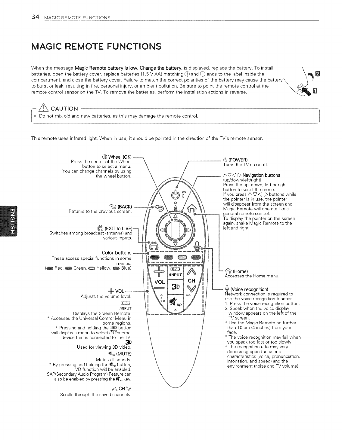
MAGIC REMOTE FUNCTIONS
When the message Magic Remote battery is low. Change the battery, is displayed, replace the battery. To install \
batteries, open the battery cover, replace batteries (1.5 V AA) matching (_) and (-} ends to the label inside the \8
compartment, and close the battery cover. Failure to match the correct polarities of the battery may cause the battery_ .. I y
to burst or leak, resulting in fire, personal injury, or ambient pollution. Be sure to point the remote control at the ___ 8
remote control sensor on the TV. To remove the batteries, perform the installation actions in reverse.
[ A CAUTION
Do not mix old and new batteries, as this may damagethe remote control.
This remote uses infrared light. When in use, it should be pointed in the direction of the TV's remote sensor.
Q Wheel (OK)
Press the center of the Wheet
button to select a menu.
You can change channels by using
the wheel button.
(BACK)
Returns to the previous screen.
Switches among broadcast (antenna) and
various inputs.
(_)(POWER)
Turns the TV on or off.
_7 <3 D Navigation buttons
(up/down/left!right)
Press the up, down, left or right
button to scroll the menu.
If you press _<(] _:>buttons while
the pointer is in use, the pointer
will disappear from the screen and
Magic Remote will operate like a
general remote control.
To display the pointer on the screen
again, shake Magic Remote to the
left and right.
These access speciai functions in some
menus.
(_ Red, _ Green, _ Yellow, _ Blue)
Adjusts the volume level.
[_
/INPUT
Displays the Screen Remote.
* Accesses the Universal Control Menu in
some regions.
* Pressing and holding the f£2J[3]button
/INPUT
will display a menu to select an external
device that is connected to the TV.
Used for viewing 3D video.
_o (MUTE)
Mutes all sounds.
* By pressing and holding the _o button,
VD function wilt be enabled.
SAP(Secondary Audio Program) Feature can
also be enabled by pressing the _o key.
ACH_
Scrolls through the saved channels.
(Home)
Accesses the Home menu.
@ (Voice recognition)
Network connection is required to
use the voice recognition function.
1. Press the voice recognition button.
2. Speak when the voice display
window appears on the left of the
TV screen.
* Use the Magic Remote no further
than 10 cm (4 inches) from your
face.
* The voice recognition may fail when
you speak too fast or too slowly.
* The recognition rate may vary
depending upon the user's
characteristics (voice, pronunciation,
intonation, and speed) and the
environment (noise and TV volume).
MAGICREMOTEFUNCTIONS35
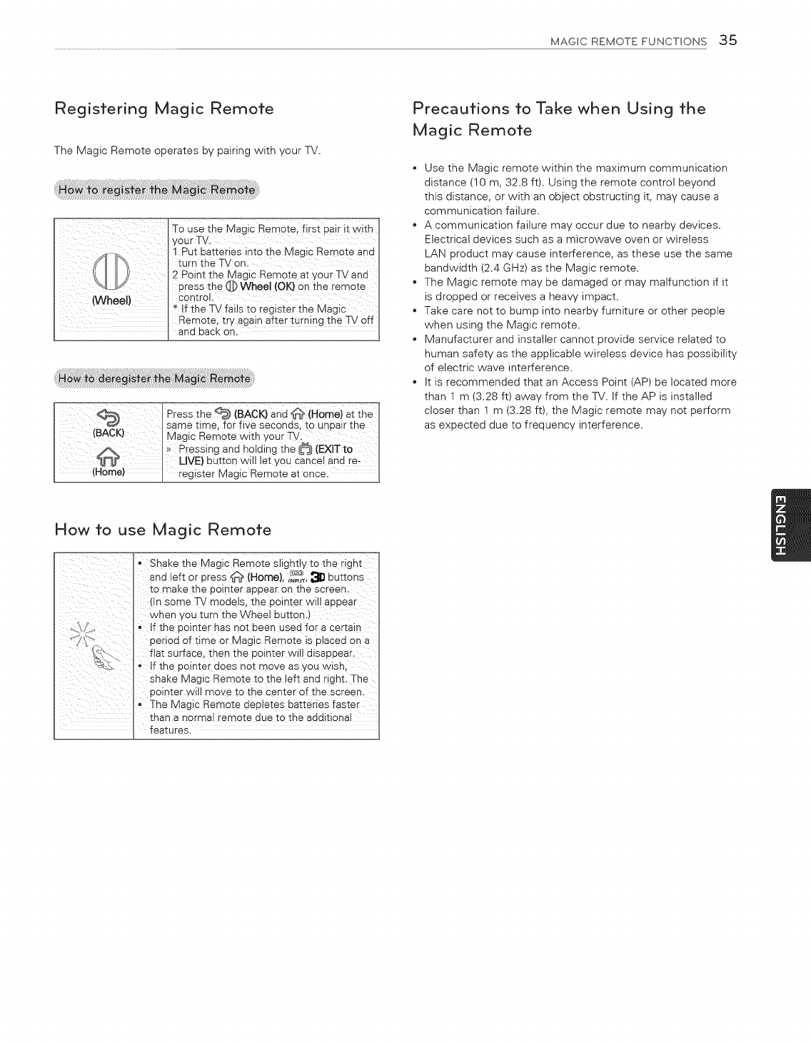
Registering Magic Remote
The Magic Remote operates by pairing with your TV.
TO Use the Magic Remote_ firs t pa ir it with
I y0ur TV.
1 Put batteries into the Magic Remote and
turn the TV on.
2 Point the Magic Remote at your TV and
press the @ Whee! (OK) on the remote
Control.
(Whee!) *If the TV fails tO register the Magic
Remote, try again after turning the TV off
and back on.
_ress the _ (BACK)and _ (Home)at the I
/_ K I same time, for five seconds, to unpair the
(B C ) ! Magic Remote with your TV:
I}> Pressing and hotding the _ (EXlT to
_ _ LIVE) button will let YOU Cancel and re- I
(Home) .... _ register Magic Remote at Once. I
Precautions to Take when Using the
Magic Remote
Use the Magic remote within the maximum communication
distance (10 m, 32.8 ft). Using the remote control beyond
this distance, or with an object obstructing it, may cause a
communication failure.
A communication failure may occur due to nearby devices.
Electrical devices such as a microwave oven or wireless
LAN product may cause interference, as these use the same
bandwidth (2.4 GHz) as the Magic remote.
The Magic remote may be damaged or may malfunction if it
is dropped or receives a heavy impact.
Take care not to bump into nearby furniture or other people
when using the Magic remote.
Manufacturer and installer cannot provide service related to
human safety as the applicable wireless device has possibility
of electric wave interference.
it is recommended that an Access Point rAP) be located more
than 1 m (3.28 ft) away from the TV. if the AP is installed
closer than 1 m (3.28 ft), the Magic remote may not perform
as expected due to frequency interference.
How to use Magic Remote
- Shake the Magic Remote slightly to the right
and left or Dress _*_ (Home), ,_'_T, _ buttons
to maKe me aolnter appear on the screen.
dn some TV modets, the pointer will appear
wnen you turn the Wheel button.)
If the uointer has not been used for a certain
aenod of time or Magic Remote ts ulacea on a
fiat surface, then the pointer wi I disappear.
o If the uointer aces not move as _,ou wtsh,
shake Magic Remo_e to me left and right. The
aointer will move to the center of the screen.
The Magic Remote depletes batteries faster
than a normal remote aue to me addition8
features.
36 USINGTHE USER GUIDE
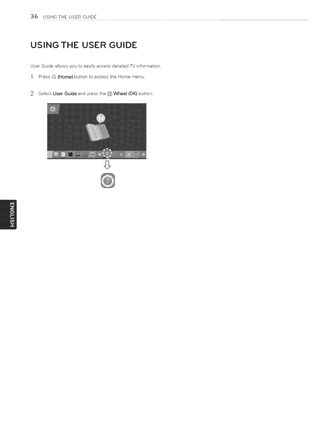
USING THE USER GUIDE
User Guide allows you to easily access detailed TV information.
1Press d_ (Home) button to access the Home menu.
2Select User Guide and press the 0 Wheel (OK) button,
SPECIFICATIONS 37
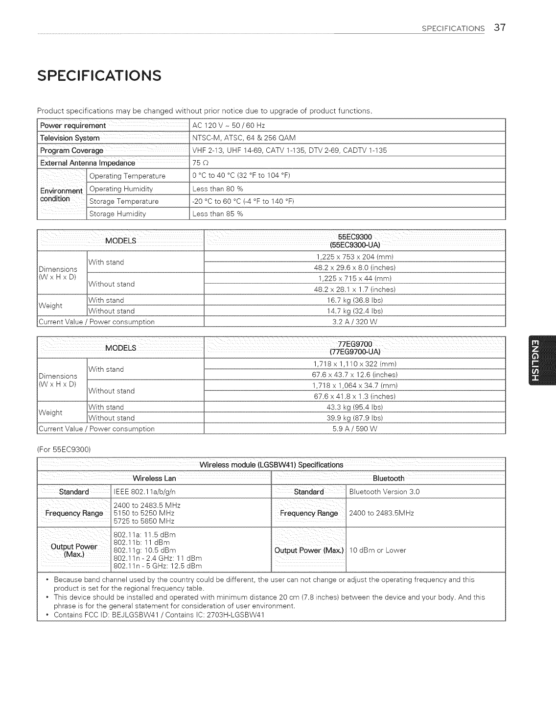
SPECIFICATIONS
Product specifications may be changed without prior notice due to upgrade of product functions.
AC 120V - 50/60 Hz
NTSC-M, ATSC, 64 & 256 QAM
Program COverage VHF 2-13, UHF 14-69, CATV 1-135, DTV 2-69, CADTV 1-135
External Antenna impedance .................................75 ©
e 0 °c to 40 °c (32 °F to 104 °F)
Less than 80 %
-20 °C to 60 °C (-4 °F to 140 °F)
_LStorage Humidity Less than 85 %
Dimensions
(WxHxD)
Weight
Current Value
With stand
Without stand
With stand
Without stand
' Power consumption
1,225 x 753 x 204 (mm)
48.2 x 29.6 x 8.0 (inches)
1,225 x 715 x 44 (mm)
48.2 x 28.1 x 1.7 (inches)
16.7 kg (36.8 Ibs)
14.7 kg (32.4 Ibs)
3.2 A /320 W
_:77EG9700
MODELS (77EGe70O-UA)
1,718 x 1,110 x 322 (mm)
With stand
Dimensions 67.6 x 43.7 x 12.6 (inches)
(W x H x D) 1,718 x 1,064 x 34.7 (mm)
Without stand 67.6 x 41.8 x 1.3 (inches)
With stand 43.3 kg (95.4 Ibs)
Weight Without stand 39.9 kg (87.9 Ibs)
Current Value ' Power consumption 5.9 A /590 W
For 55EC9300)
wirelesS moduie (LGSBW41) Specifications ...............
wireless Ean Biuet00th
standard IEEE 802.1 la/b/g/n
2400 to 2483.5 MHz
Frequency Range 5150 to 5250 MHz
5725 to 5850 MHz
802.119:11.5 dBm
Output Power 802.11 b: 11 dBm
802.11g: 10.5 dBm
(Max.) 802.11n - 2.4 GHz: 11 dBm
802.11n - 5 GHz: 12.5 dBm
standard Bluetooth Version 3.0
Frequency Range 2400 to 2483.5MHz
0utpUt PoWer (Max:) 10 dBm or Lower
Because band channel used by the country could be different, the user can not change or adjust the operating frequency and this
product is set for the regional frequency table.
This device should be installed and operated with minimum distance 20 cm (7.8 inches) between the device and your body. And this
phrase is for the general statement for consideration of user environment.
Contains FCC ID: BEJLGSBW41 /Contains IC: 2703H-LGSBW41
38 SPECWBCATBONS/EXTERNAL CONTROL DEVSCE SETUP
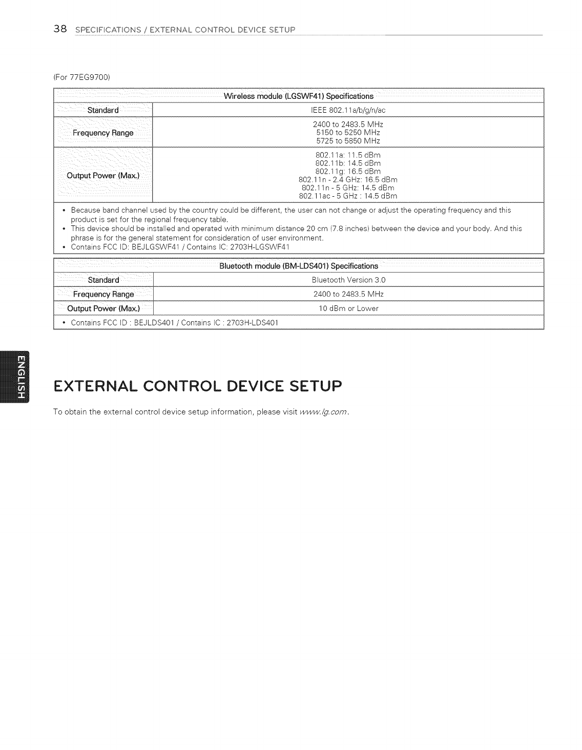
(For 77EG9700)
Wireless module (LGSWF41} Specifications
IEEE 802.11 a/b/g/n/ac
Frequency Range
Output Power (MAX)
2400 to 2483.5 MHz
5150 to 5250 MHz
5725 to 5850 MHz
802.11a: 11.5 dBm
802.11b: 14.5 dBm
802.11g: 16.5 dBm
802.11n - 2.4 GHz: 16.5 dBm
802.11n - 5 GHz: 14.5 dBm
802.11ac- 5 GHz : 14.5 dBm
Because band channel used by the country could be different, the user can not change or adjust the operating frequency and this
product is set for the regional frequency table.
This device should be installed and operated with minimum distance 20 cm (7.8 inches) between the device and your body. And this
phrase is for the general statement for consideration of user environment.
Contains FCC ID: BEJLGSWF41 /Contains IC: 2703H-LGSWF41
%uetooth Version 3.0
..... 2#00 to 2483.5 MHz
...... 10 dBm or Lower
_ins FCC ID : BEJLDS401 /Contains IC : 2703H-LDS401
EXTERNAL CONTROL DEVICE SETUP
To obtain the external control device setup information, please visit www./g.com.
MAINTENANCE/TROUBLESHOOTING 39
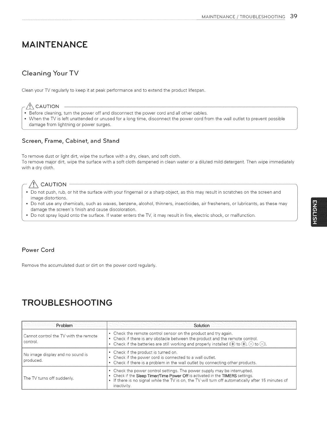
MAINTENANCE
Cleaning Your TV
Clean your TV regularly to keep it at peak performance and to extend the product lifespan.
--_s CAUTION
Before cleaning, turn the power off and disconnect the power cord and all other cables.
When the TV is left unattended or unused for a long time, disconnect the power cord from the wall outlet to prevent possible
damage from lightning or power surges.
Screen, Frame, Cabinef, and Sfand
To remove dust or light dirt, wipe the surface with a dry, clean, and soft cloth.
To remove major dirt, wipe the surface with a soft cloth dampened in clean water or a diluted mild detergent. Then wipe immediately
with a dry cloth.
oAum,oN
• Do not push, rub, or hit the surface with your fingernail or a sharp object, as this may result in scratches on the screen and
image distortions.
Do not use any chemicals, such as waxes, benzene, alcohol, thinners, insecticides, air fresheners, or lubricants, as these may
damage the screen's finish and cause discoloration.
Do not spray liquid onto the surface, tf water enters the TV, it may result in fire, electric shock, or malfunction. J
Power Cord
Remove the accumulated dust or dirt on the power cord regularly.
TROUBLESHOOTING
Problem SolUtion
Check the remote control sensor on the product and try again.
Cannot control the TV with the remote Check if there is any obstacle between the product and the remote control.
control. • Check if the batteries are still working and properly installed (,_+_to (_+_,\-/to \-/).
• Check if the product is turned on.
No image display and no sound is • Check if the power cord is connected to a wall outlet.
produced. • Check if there is a problem in the wall outlet by connecting other products.
• Check the power control settings. The power supply may be interrupted.
Check if the Sleep Timerfrime Power Off is activated in the TIMERS settings.
The TV turns off suddenly. • If there is no signal while the TV is on, the TV will turn off automatically after 15 minutes of
inactivity.

PROPER TELEVISION PLACEMENT
[]
[]
MATTERS
THE CONSUMER ELECTRONICS INDUSTRY CARES
° Manufacturers, retailers and the rest of the consumer electronics industry are committed to
makin£ home entertainment safe and enjoyable.
• As you enjoy your television, please note that all Lelevisions new and old- must be supported on
proper stands or installed accordin£ to the manufacturer's recommendations. Televisions that
are inappropriately siLuated on dressers, bookcases, shelves, desks, speakers, chests, carts, etc.,
may fall over, resulLin£ in injury.
TUNE IN TO SAFETY
• ALWAYS follow Lhe manufacturer's recommendations for the safe installation of your television.
• ALWAYS read and follow all instructions for proper use of your television.
• NEVER allow children Lo climb on or play on Lhe television or Lhe furniLure on which Lhe television
is placed.
• NEVER place Lhe Lelevision on furniLure Lhat can easily be used as steps, such as a chest of
drawers.
• ALWAYS install Lhe television where it cannot be pushed, pulled over or knocked down.
• ALWAYS rouLe cords and cables connected Lo Lhe Lelevision so Lhat Lhey cannot be Lripped
over, pulled or £rabbed.
WALL OR CEILING MOUNT YOUR TELEVISION
• ALWAYS contact your retailer about professional installation if you have any doubts about'your
ability to safely mounL your Lelevision.
• ALWAYS use a mount that has been recommended by Lhe television manufacturer and has a
safety cerCification by an independenL laboratory {such as UL, CSA, ETL).
• ALWAYS follow all instructions supplied by the Lelevision and mounL manufacturers.
• ALWAYS make sure that the wall or ceilin£ where you are mountin£ the television is appropriate.
Some mounLs are not desi£ned to be mounted to walls and ceilin£s wiLh steel studs or cinder
block construction. If you are unsure, contact a professional installer.
• Televisions can be heavy. A minimum of Lwo people is required for a wall or ceilin£ mounL
installation.
MOVING AN OLDER TELEVISION TO A NEW PLACE IN
YOUR HOME
• Many new television buyers move their older CRT televisions into a secondary room after the
purchase of a flat-panel Lelevision. Special care should be made in Lhe placemenL of older CRT
Lelevisions.
• ALWAYS place your older CRT Lelevision on furniLure Lhat is sturdy and appropriate for iLs size
and wei£ht.
• NEVER place your older CRT Lelevision on a dresser where children may be Lempted Lo use Lhe
drawers to climb.
• ALWAYS make sure your older CRT Lelevision does not han£ over Lhe ed£e of your furniture.
CE.org/safety
Life's Good
ii i _
_iii iiii
i_,il
_%_ _ _ _ _ _C¸_'_'_¸R_ _ _ • "
EXTERNAL
DEVICE SE CONT
TUP OL
Please read this manual carefully before operating the set and retain it for
future reference.
www.lg.corn
2 KEY CODES
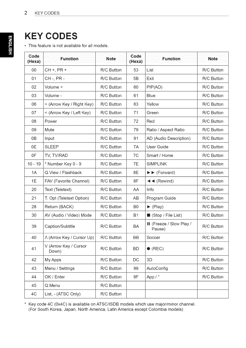
KEY CODES
This feature is not available for all models.
Code
(Hexa)
00
01
O2
O3
O6
O7
O8
O9
0B
0E
OF
10-19
1A
1E
20
21
28
30
39
40
41
42
43
44
45
4C
Function NOte Code
(Hexa)
CH +, PR + R!C Button
CH -, PR - R/C Button
Volume + R!C Button
Volume - R/C Button
> (Arrow Key /Right Key) R/C Button
< (Arrow Key /Left Key) R/C Button
Power R!C Button
Mute R!C Button
Input R!C Button
SLEEP R/C Button
TV, TV/RAD R/C Button
* Number Key 0 - 9 R/C Button
Q.View /Flashback R/C Button
FAV (Favorite Channel) R/C Button
Text (Tetetext) R/C Button
T. Opt (Tetetext Option) R/C Button
Return (BACK) R/C Button
AV (Audio /Video) Mode R/C Button
Caption/Subtitle R/C Button
A (Arrow Key /Cursor Up) R/C Button
V (Arrow Key /Cursor R!C Button
Down)
My Apps R/C Button
Menu /Settings R!C Button
OK/Enter R/C Button
Q.Menu R/C Button
List, - (ATSC Only) R/C Button
53
5B
60
61
63
71
72
79
91
7A
7C
7E
8E
8F
AA
AB
B0
BI
BA
BB
BD
DC
99
9F
List R!C Button
Exit R!C Button
PIP(AD) R!C Button
Blue R/C Button
Yellow R!C Button
Green R!C Button
Red R!C Button
Ratio /Aspect Ratio R/C Button
AD (Audio Description) R/C Button
User Guide R/C Button
Smart /Home R!C Button
SIMPLINK R!C Button
I_ I_ (Forward) R/C Button
4 4 (Rewind) R/C Button
Info R!C Button
Program Guide R/C Button
I_ (Play) R/C Button
ml (Stop /File List) R/C Button
II (Freeze /Slow Play /R/C Button
Pause)
Soccer R/C Button
® (REC) R/C Button
3D R/C Button
AutoConfig R/C Button
App /* R/C Button
Function Note
* Key code 4C (0x4C) is available on ATSC/ISDB models which use major/minor channel.
(For South Korea, Japan, North America, Latin America except Colombia models)
EXTERNALCONTROLDEVICESETUP3
EXTERNAL CONTROL DEVICE SETUP
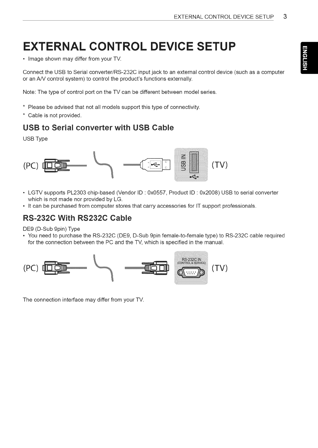
Image shown may differ from your TV.
Connect the USB to Serial converter/RS-232C input jack to an external control device (such as a computer
or an A/V control system) to control the product's functions externally.
Note: The type of control port on the TV can be different between model series.
* Please be advised that not all models support this type of connectivity.
* Cable is not provided.
USB to Serial converter with USB Cable
USB Type
(PC) (TV)
LGTV supports PL2303 chip-based (Vendor ID " 0x0557, Product ID " 0x2008) USB to serial converter
which is not made nor provided by LG.
It can be purchased from computer stores that carry accessories for IT support professionals.
RS-232C With RS232C Cable
DE9 (D-Sub 9pin) Type
You need to purchase the RS-232C (DE9, D-Sub 9pin female-to-female type) to RS-232C cable required
for the connection between the PC and the TV, which is specified in the manual.
(PC) (TV)
The connection interface may differ from your TV.
4EXTERNAL CONTROL DEVICE SETUP
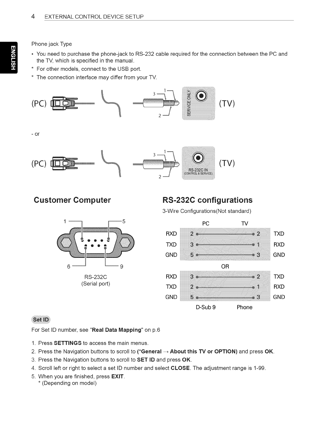
Phone jack Type
You need to purchase the phone-jack to RS-232 cable required for the connection between the PC and
the TV, which is specified in the manual.
* For other models, connect to the USB port.
* The connection interface may differ from your TV.
(PC) (TV)
- or
(PC)
Customer Computer
6 --
RS-232C
(Serial port)
RS=232C configurations
3-Wire Configurations(Not standard)
PC TV
RXD
TXD
G.D
OR
RXD
TXD
GND
D-Sub 9 Phone
TXD
RXD
GND
TXD
RXD
GND
For Set ID number, see "Real Data Mapping" on p.6
1. Press SETTINGS to access the main menus.
2. Press the Navigation buttons to scroll to (*General _ About this TV or OPTION) and press OK.
3. Press the Navigation buttons to scroll to SET ID and press OK.
4. Scroll left or right to select a set ID number and select CLOSE. The adjustment range is 1-99.
5. When you are finished, press EXIT.
* (Depending on model)
EXTERNALCONTROLDEVICESETUP5
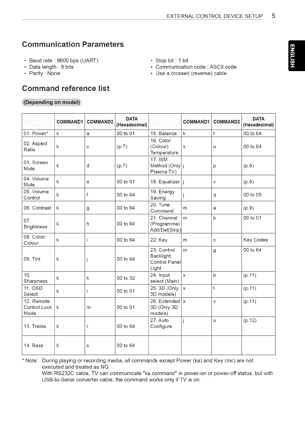
Communication Parameters
Baud rate " 9600 bps (UART)
Data length " 8 bits
Parity None
Command reference list
Stop bit 1 bit
Communication code : ASCII code
, Use a crossed (reverse) cable.
COMMA.D1
01. Power* k
02. Aspect k
Ratio
COMMAND2
a
c O0 to 64
03. Screen k d (p.8)
Mute
04. Volume k e (p.8)
Mute
05. Volume k f O0 to 05
Control
06. Contrast k g (p.9)
07. 00 to 01
k h
Brightness
08. Color/ k Key Codes
Colour
00 to 64
09. Tint k
10. k k (p.11)
Sharpness
11. OSD k (p.11)
Select
12. Remote (p.11)
Control Lock k m
Mode
(p.12)
13. Treble k r
14. Bass k s 00 to 64
Note: During playing or recording media, all commands except Power (ka) and Key (mc) are not
executed and treated as NG.
With RS232C cable, TV can communicate "ka command" in power-on or power-off status, but with
USB-to-Serial converter cable, the command works only if TV is on.
-- Hexadecimal i
00 to 01 15. Balance
16. Color
(p.7) (Colour)
Temperature
17. ISM
(p.7) Method (Only
Plasma TV)
00 to 01 18. Equalizer
19. Energy
00 to 64 Saving
20. Tune
00 to 64 Command
21. Channel
00 to 64 (Programme)
Add/Del(Skip)
00 to 64 22. Key
23. Control
00 to 64 Backlight,
Control Panel
Light
24. Input
00 to 32 select (Main)
25.3D (Only
00 to 01 3D models)
26. Extended
00 to 01 3D (Only 3D
models)
27. Auto
00 to 64 Configure
COMMANDI COMMAND2
k!
X U
P
V
q
m a
m b
mc
m g
x b
x t
X V
U
OATA
(Hexadecimal)
O0 to 64
6 EXTERNAL CONTROL DEVICE SETUP
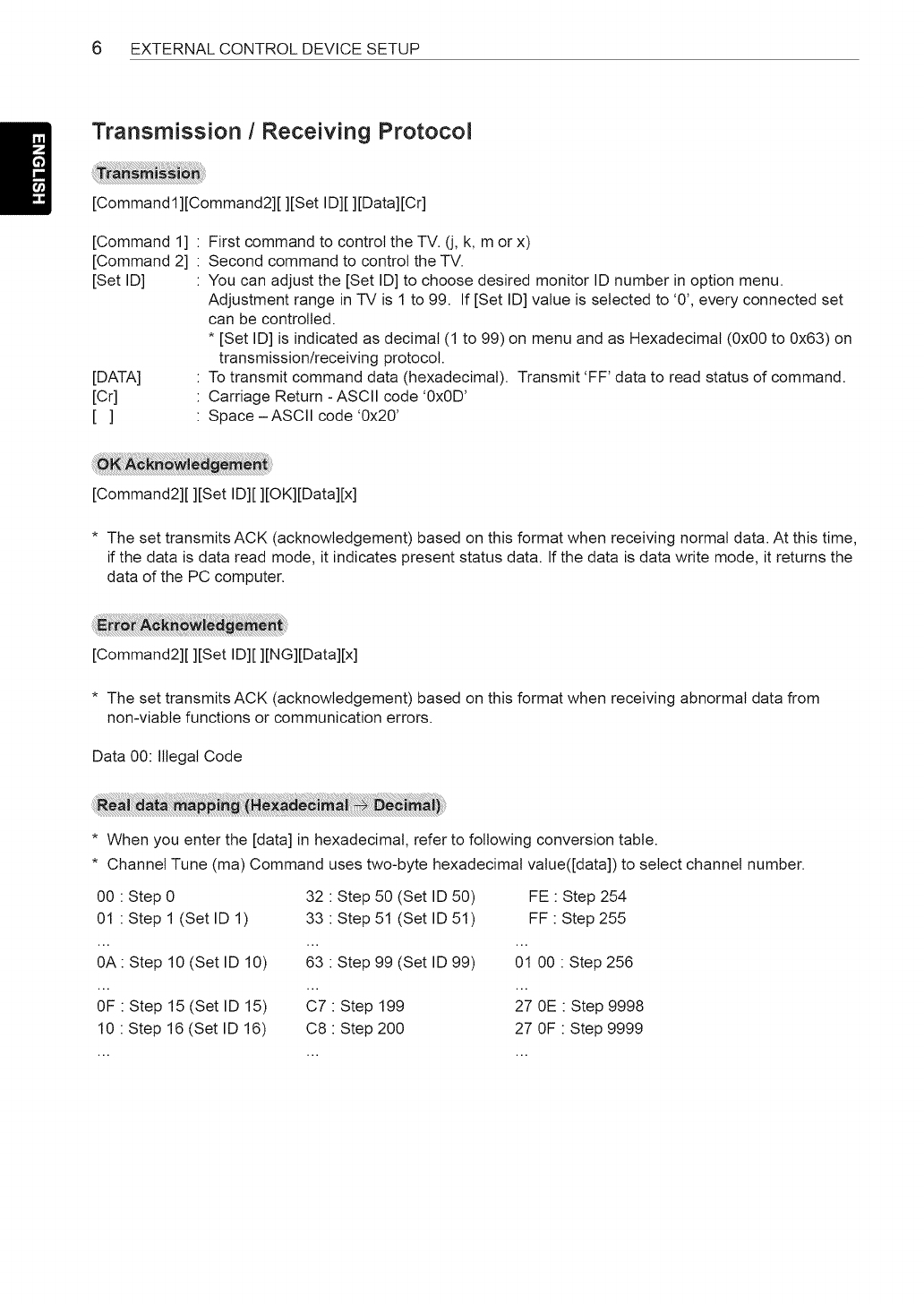
Transmission /Receiving Protocol
[Commandl][Command2][ ][Set ID][ ][Data][Cr]
[Command 1]
[Command 2]
[Set ID]
[DATA]
[Cr]
[]
First command to control the TV. (j, k, m or x)
Second command to control the TV.
You can adjust the [Set ID] to choose desired monitor ID number in option menu.
Adjustment range in TV is 1 to 99. If [Set ID] value is selected to '0', every connected set
can be controlled.
* [Set ID] is indicated as decimal (1 to 99) on menu and as Hexadecimal (0x00 to 0x63) on
transmission/receiving protocol.
To transmit command data (hexadecimal). Transmit 'FF' data to read status of command.
Carriage Return - ASCII code '0x0D'
Space - ASCII code '0x20'
[Command2][ ][Set ID][ ][OK][Data][x]
* The set transmits ACK (acknowledgement) based on this format when receiving normal data. At this time,
if the data is data read mode, it indicates present status data. If the data is data write mode, it returns the
data of the PC computer.
[Command2][ ][Set ID][ ][NG][Data][x]
* The set transmits ACK (acknowledgement) based on this format when receiving abnormal data from
non-viable functions or communication errors.
Data 00: Illegal Code
* When you enter the [data] in hexadecimal, refer to following conversion table.
* Channel Tune (ma) Command uses two-byte hexadecimal value([data]) to select channel number.
00 : Step 0 32 : Step 50 (Set ID 50) FE : Step 254
01 : Step 1 (Set ID 1) 33 : Step 51 (Set ID 51) FF : Step 255
0A: Step 10 (Set ID 10) 63 : Step 99 (Set ID 99) 01 00 : Step 256
OF : Step 15 (Set ID 15) C7 : Step 199 27 0E : Step 9998
10 : Step 16 (Set ID 16) C8 : Step 200 27 OF : Step 9999
EXTERNALCONTROLDEVICESETUP 7
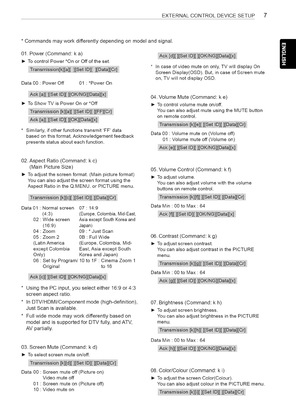
* Commands may work differently depending on model and signal.
01. Power (Command: k a)
I_ To control Power *On or Off of the set.
Data 00 : Power Off 01 : *Power On
* In case of video mute on only, TV will display On
Screen Display(OSD). But, in case of Screen mute
on, TV will not display OSD.
I_ To Show TV is Power On or *Off
04. Volume Mute (Command: k e)
I_ To control volume mute on/off.
You can also adjust mute using the MUTE button
on remote control.
* Similarly, if other functions transmit 'FF' data
based on this format, Acknowledgement feedback
presents status about each function.
02. Aspect Ratio (Command: k c)
(Main Picture Size)
I_ To adjust the screen format. (Main picture format)
You can also adjust the screen format using the
Aspect Ratio in the Q.MENU. or PICTURE menu.
Data 01 : Normal screen
(4:3)
02 : Wide screen
(16:9)
04 : Zoom
05 : Zoom 2
(Latin America
except Colombia
Only)
07 : 14:9
(Europe, Colombia, Mid-East,
Asia except South Korea and
Japan)
09 : * Just Scan
0B : Full Wide
(Europe, Colombia, Mid-
East, Asia except South
Korea and Japan)
06 : Set by Program/10 to IF : Cinema Zoom 1
Original to 16
* Using the PC input, you select either 16:9 or 4:3
screen aspect ratio.
* In DTV/HDMI/Component mode (high-definition),
Just Scan is available.
* Full wide mode may work differently based on
model and is supported for DTV fully, and AT',/,
AV partially.
03. Screen Mute (Command: k d)
I_ To select screen mute on/off.
Data 00 : Volume mute on (Volume off)
01 : Volume mute off (Volume on)
05. Volume Control (Command: k f)
I_ To adjust volume.
You can also adjust volume with the volume
buttons on remote control.
i i r]
Data Min : 00 to Max : 64
06. Contrast (Command: k g)
I_ To adjust screen contrast.
You can also adjust contrast in the PICTURE
menu.
Data Min : 00 to Max : 64
i i
07. Brightness (Command: k h)
I_ To adjust screen brightness.
You can also adjust brightness in the PICTURE
menu.
Data Min : 00 to Max : 64
Data 00 : Screen mute off (Picture on)
Video mute off
01 : Screen mute on (Picture off)
10 : Video mute on
08. Color/Colour (Command: k i)
I_ To adjust the screen Color(Colour).
You can also adjust colour in the PICTURE menu.
8 EXTERNAL CONTROL DEVICE SETUP
Data Min : 00 to Max : 64
09. Tint (Command: k j)
_- To adjust the screen tint.
You can also adjust tint in the PICTURE menu.
Data Red : 00 to Green : 64
10. Sharpness (Command: k k)
_- To adjust the screen sharpness.
You can also adjust sharpness in the PICTURE
menu.
Data Min : 00 to Max : 32
* (Depending on model)
14. Bass (Command: k s)
_- To adjust Bass.
You can also adjust in the AUDIO menu.
Data Min : 00 to Max : 64
* (Depending on model)
15. Balance (Command: k t)
_- To adjust balance.
You can also adjust balance in the AUDIO menu.
Data Min : 00 to Max : 64
11. OSD Select (Command: k l)
_- To select OSD (On Screen Display) on/off when
controlling remotely.
Data 00 : OSD off 01 : OSD on
12. Remote control lock mode (Command: k m)
_- To lock the front panel controls on the monitor and
remote control.
Data 00 : Lock off 01 : Lock on
16. Color(Colour) Temperature (Command: x u)
_- To adjust colour temperature. You can also adjust
Color(Colour) Temperature in the PICTURE menu.
Data Min : 00 to Max : 64
17. ISM Method (Command: j p) (Only Plasma TV)
_- To control the ISM method. You can also adjust
ISM Method in OPTION menu.
Data Min : 02: Orbiter
08: Normal
20: Color(Colour) Wash
* If you are not using the remote control, use this
mode.
When main power is off & on (plug-off and plug-in,
after 20 - 30 seconds), external control lock is
released.
* In the standby mode (DC off by off timer or 'ka',
'mc' command), and if key lock is on, TV will not
turn on by power on key of IR & Local Key.
13. Treble (Command: k r)
_- To adjust treble.
You can also adjust in the AUDIO menu.
Data Min : 00 to Max : 64
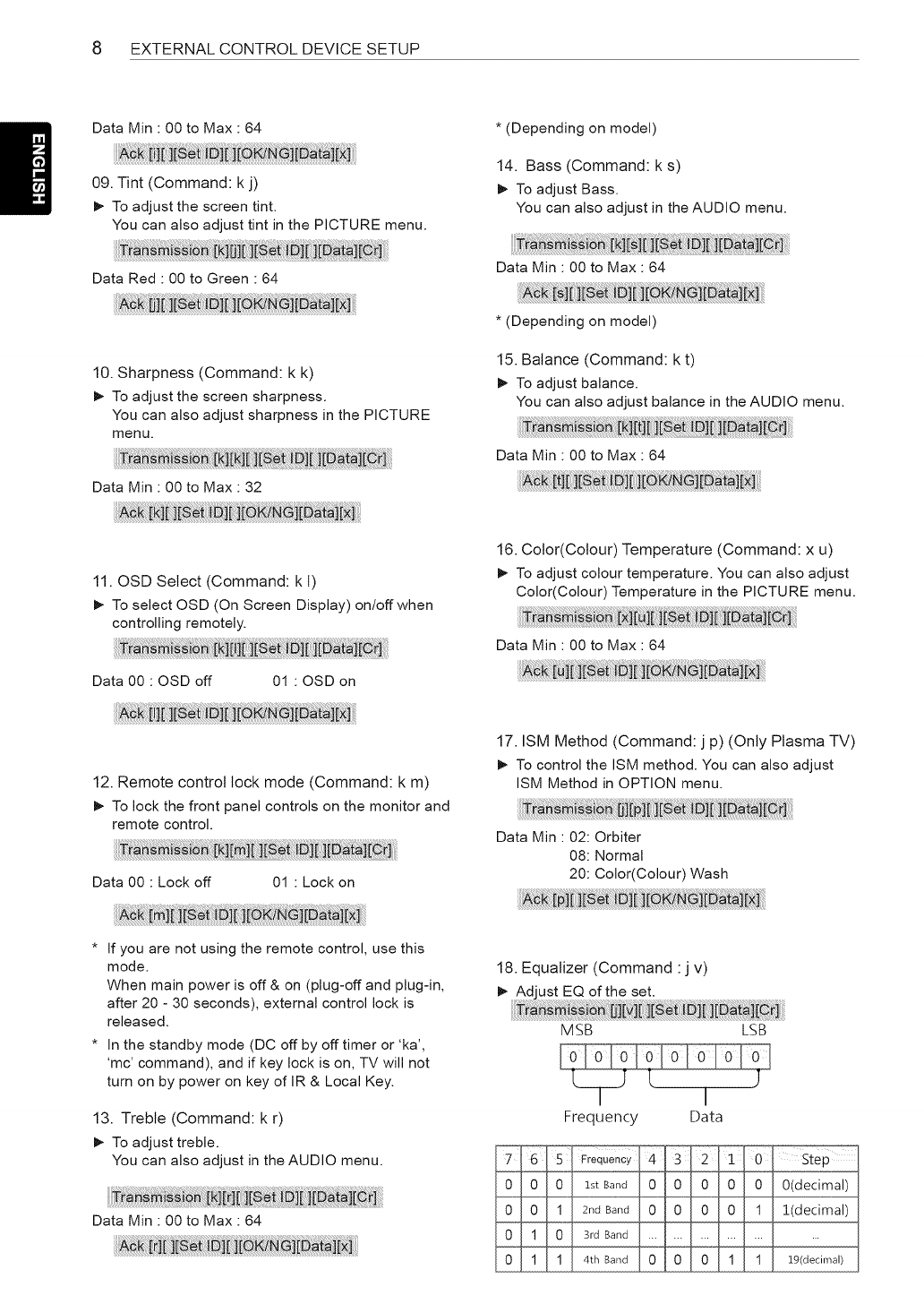
18. Equalizer (Command :j v)
MSB LSB
Frequency Data
,_Step "
O(decimal)
1!decimal)
19(decu-nal)
EXTERNALCONTROLDEVICESETUP 9
* It depends on model, and can adjust when sound
mode is EQ adjustable value.
19. Energy Saving (Command: j q)
_- To reduce the power consumption of the TV. You
can also adjust Energy Saving in PICTURE menu.
Data
00 : Off
01 : Minimum
02 : Medium
03 : Maximum
04 : Auto (For LCD TV /LED TV) /
Intelligent sensor (For PDP TV)
05 : Screen off
* (Depending on model)
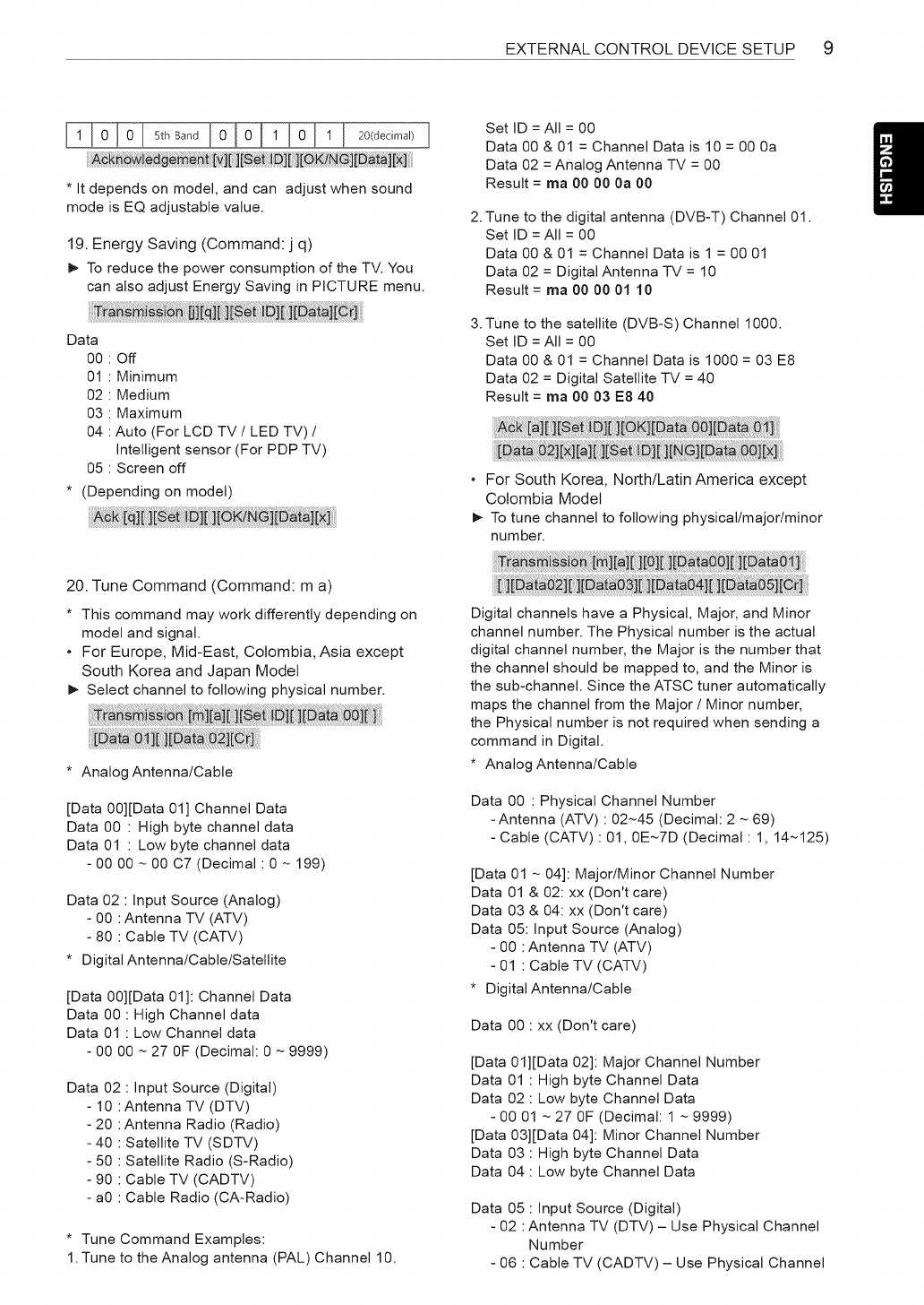
2.
3.
Set ID = All = 00
Data 00 & 01 = Channel Data is 10 = 00 0a
Data 02 = Analog Antenna TV = 00
Result = ma 00 00 0a 00
Tune to the digital antenna (DVB-T) Channel 01.
Set ID = All = 00
Data 00 & 01 = Channel Data is 1 = 00 01
Data 02 = Digital Antenna TV = 10
Result = ma 00 00 01 10
Tune to the satellite (DVB-S) Channel 1000.
Set ID = All = 00
Data 00 & 01 = Channel Data is 1000 = 03 E8
Data 02 = Digital Satellite TV = 40
Result = ma 00 03 E8 40
. For South Korea, North/Latin America except
Colombia Model
_- To tune channel to following physical/major/minor
number.
20. Tune Command (Command: m a)
* This command may work differently depending on
model and signal.
- For Europe, Mid-East, Colombia, Asia except
South Korea and Japan Model
_- Select channel to following physical number.
* Analog Antenna/Cable
[Data 00][Data 01] Channel Data
Data 00 : High byte channel data
Data 01 : Low byte channel data
- 00 00 ~ 00 C7 (Decimal: 0 ~ 199)
Data 02 : Input Source (Analog)
- 00 :Antenna TV (ATV)
- 80 : Cable TV (CATV)
* Digital Antenna/Cable/Satellite
[Data 00][Data 01]: Channel Data
Data 00 : High Channel data
Data 01 : Low Channel data
- 00 00 ~ 27 OF (Decimal: 0 ~ 9999)
Data 02 : Input Source (Digital)
- 10 :Antenna TV (DTV)
- 20 :Antenna Radio (Radio)
- 40 : Satellite TV (SDTV)
- 50 : Satellite Radio (S-Radio)
- 90 : Cable TV (CADTV)
- a0 : Cable Radio (CA-Radio)
* Tune Command Examples:
1. Tune to the Analog antenna (PAL) Channel 10.
Digital channels have a Physical, Major, and Minor
channel number. The Physical number is the actual
digital channel number, the Major is the number that
the channel should be mapped to, and the Minor is
the sub-channel. Since the ATSC tuner automatically
maps the channel from the Major /Minor number,
the Physical number is not required when sending a
command in Digital.
* Analog Antenna/Cable
Data 00 : Physical Channel Number
-Antenna (ATV) : 02~45 (Decimal: 2 ~ 69)
- Cable (CATV) : 01, 0E~7D (Decimal: 1, 14~125)
[Data 01 ~ 04]: Major/Minor Channel Number
Data 01 & 02: xx (Don't care)
Data 03 & 04: xx (Don't care)
Data 05: Input Source (Analog)
- 00 :Antenna TV (ATV)
- 01 : Cable TV (CATV)
* Digital Antenna/Cable
Data 00 : xx (Don't care)
[Data 01][Data 02]: Major Channel Number
Data 01 : High byte Channel Data
Data 02 : Low byte Channel Data
- 00 01 ~ 27 OF (Decimal: 1 ~ 9999)
[Data 03][Data 04]: Minor Channel Number
Data 03 : High byte Channel Data
Data 04 : Low byte Channel Data
Data 05 : Input Source (Digital)
- 02 :Antenna TV (DTV) - Use Physical Channel
Number
- 06 : Cable TV (CADTV) - Use Physical Channel
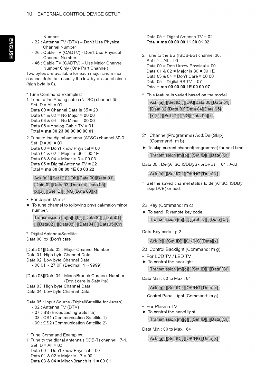
10 EXTERNAL CONTROL DEVICE SETUP
Number
- 22 :Antenna TV (DTV) - Don't Use Physical
Channel Number
- 26 : Cable TV (CADTV) - Don't Use Physical
Channel Number
- 46 : Cable TV (CADTV) - Use Major Channel
Number Only (One Part Channel)
Two bytes are available for each major and minor
channel data, but usually the low byte is used alone
(high byte is 0).
* Tune Command Examples:
1. Tune to the Analog cable (NTSC) channel 35.
Set ID = All = 00
Data 00 = Channel Data is 35 = 23
Data 01 & 02 = No Major = 00 00
Data 03 & 04 = No Minor = 00 00
Data 05 = Analog Cable TV = 01
Total = ma O0 23 90 90 90 90 91
2. Tune to the digital antenna (ATSC) channel 30-3.
Set ID = All = 00
Data 00 = Don't know Physical = 00
Data 01 & 02 = Major is 30 = 00 1E
Data 03 & 04 = Minor is 3 = 00 03
Data 05 = Digital Antenna TV = 22
Total = ma 00 00 00 1E 00 03 22
Data 05 = Digital Antenna TV = 02
Total = ma 90 90 90 11 O0 01 02
2. Tune to the BS (ISDB-BS) channel 30.
Set ID = All = 00
Data 00 = Don't know Physical = 00
Data 01 & 02 = Major is 30 = 00 1E
Data 03 & 04 = Don't Care = 00 00
Data 05 = Digital BS TV = 07
Total = ma 90 00 90 1E O0 90 97
* This feature is varied based on the model.
21. Channel(Programme) Add/Dei(Skip)
(Command: m b)
_- To skip current channel(programme) for next time.
Data 00 : DeI(ATSC,ISDB)/Skip(DVB) 01 : Add
!i!i!i!i !! i i !ii iii iiii ii ii !ijiii !i i!i !ii!i i i ii i
For Japan Model
_- To tune channel to following physical/major/minor
number.
* Digital Antenna/Satellite
Data 00: xx (Don't care)
[Data 01][Data 02]: Major Channel Number
Data 01: High byte Channel Data
Data 02: Low byte Channel Data
- 00 01 ~ 27 OF (Decimal: 1 ~ 9999)
[Data 03][Data 04]: Minor/Branch Channel Number
(Don't care in Satellite)
Data 03: High byte Channel Data
Data 04: Low byte Channel Data
Data 05 : Input Source (Digital/Satellite for Japan)
- 02 :Antenna TV (DTV)
- 07 : BS (Broadcasting Satellite)
- 08 : CS1 (Communication Satellite 1)
- 09 : CS2 (Communication Satellite 2)
* Tune Command Examples:
1 Tune to the digital antenna (ISDB-T) channel 17-1.
Set ID = All = 00
Data 00 = Don't know Physical = 00
Data 01 & 02 = Major is 17 = 00 11
Data 03 & 04 = Minor/Branch is 1 = 00 01
* Set the saved channel status to deI(ATSC, ISDB)/
skip(DVB) or add.
22. Key (Command: m c)
_- To send IR remote key code.
Data Key code -p.2.
23. Control Backtight (Command: m g)
,For LCD TV /LED TV
_- To control the backlight.
Data Min : 00 to Max : 64
Control Panel Light (Command: m g)
For Plasma TV
_- To control the panel light.
Data Min : 00 to Max : 64
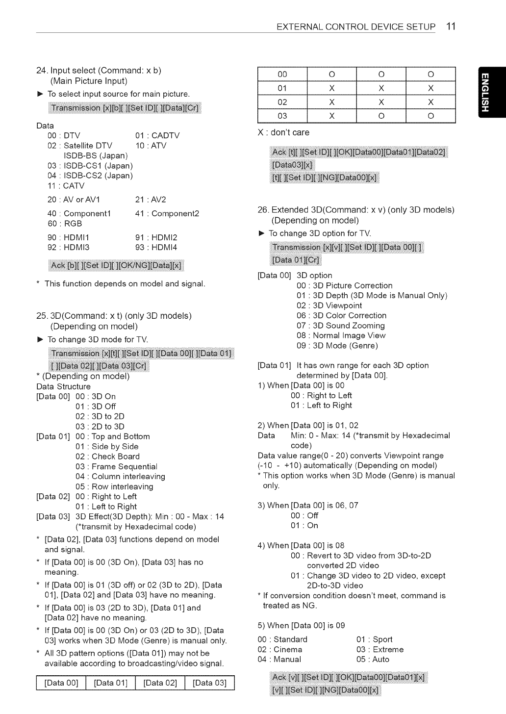
EXTERNAL CONTROL DEVICE SETUP 11
24. Input select (Command: x b)
(Main Picture Input)
_- To select input source for main picture.
Data
00
O2
O3
O4
11
DTV
Satellite DTV
ISDB-BS (Japan)
ISDB-CS1 (Japan)
ISDB-CS2 (Japan)
CATV
20 : AV orAVl
40 : Component1
60 : RGB
01 CADTV
10 ATV
21
41
90 : HDMI1 91
92 : HDMI3 93
AV2
Component2
HDMI2
HDMI4
00
01
O2
O3
X : don't care
O O O
X X X
X X X
X O O
Et i i ii:li :ii i[xi:
26. Extended 3D(Command: x v) (only 3D models)
(Depending on model)
_- To change 3D option for TV.
* This function depends on model and signal.
25.3D(Command: x t) (only 3D models)
(Depending on model)
_- To change 3D mode for TV.
* (Depending on model)
Data Structure
[Data00] 00:3DOn
01 : 3D Off
02 : 3D to 2D
03 : 2D to 3D
[Data 01] 00 : Top and Bottom
01 : Side by Side
02 : Check Board
03 : Frame Sequential
04 : Column interleaving
05 : Row interleaving
[Data 02] 00 : Right to Left
01 : Left to Right
[Data 03] 3D Effect(3D Depth): Min : 00 - Max : 14
(*transmit by Hexadecimal code)
* [Data 02], [Data 03] functions depend on model
and signal.
* If [Data 00] is 00 (3D On), [Data 03] has no
meaning.
* If [Data 00] is 01 (3D off) or 02 (3D to 2D), [Data
01], [Data 02] and [Data 03] have no meaning.
* If[Data 00] is 03 (2D to 3D), [Data 01] and
[Data 02] have no meaning.
* If [Data 00] is 00 (3D On) or 03 (2D to 3D), [Data
03] works when 3D Mode (Genre) is manual only.
* All 3D pattern options ([Data 01]) may not be
available according to broadcasting/video signal.
I [Data 00] ! [Data 01] ] [Data 02] T [Data 03]
[Data 00] 3D option
00 : 3D Picture Correction
01 : 3D Depth (3D Mode is Manual Only)
02 : 3D Viewpoint
06 : 3D Color Correction
07 : 3D Sound Zooming
08 : Normal Image View
09 : 3D Mode (Genre)
[Data 01] It has own range for each 3D option
determined by [Data 00].
1) When [Data 00] is 00
00 : Right to Left
01 : Left to Right
2) When [Data 00] is 01,02
Data Min: 0 - Max: 14 (*transmit by Hexadecimal
code)
Data value range(0 - 20) converts Viewpoint range
(-10 - +10) automatically (Depending on model)
* This option works when 3D Mode (Genre) is manual
only.
3) When [Data 00] is 06, 07
00 : Off
01 : On
4) When [Data 00] is 08
00 : Revert to 3D video from 3D-to-2D
converted 2D video
01 : Change 3D video to 2D video, except
2D-to-3D video
* If conversion condition doesn't meet, command is
treated as NG.
5) When [Data 00] is 09
00 : Standard 01 : Sport
02 : Cinema 03 : Extreme
04 : Manual 05 :Auto
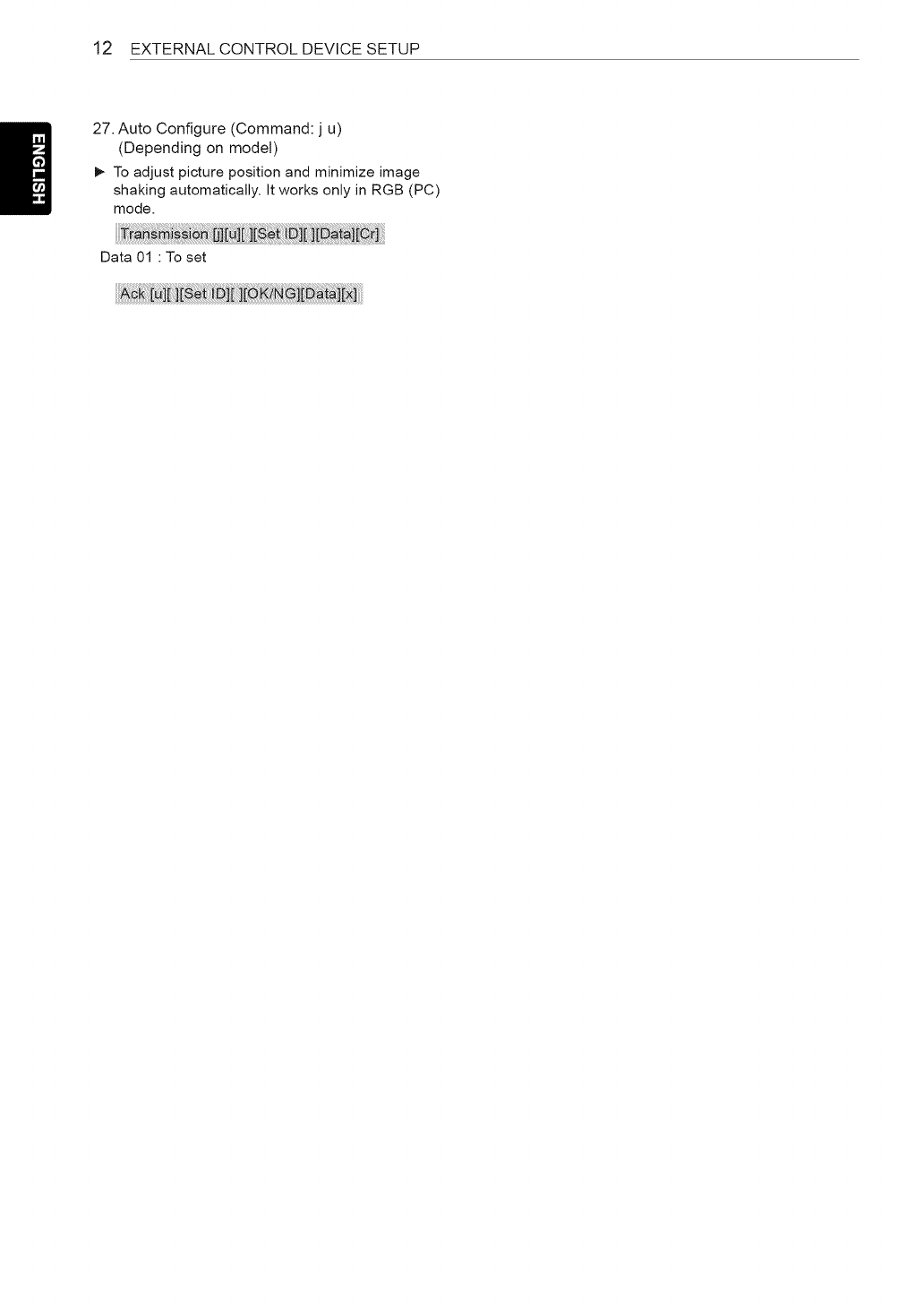
12 EXTERNAL CONTROL DEVICE SETUP
27. Auto Configure (Command: j u)
(Depending on modeS)
_- To adjust picture position and minimize image
shaking automatically. It works only in RGB (PC)
mode.
Data 01 : To set
