LG LRSP2031BS User Manual REFRIGERATOR Manuals And Guides L0301007
LG Side by Side Refrigerator Manual L0301007 LG Side by Side Refrigerator Owner's Manual, LG Side by Side Refrigerator installation guides
User Manual: LG LRSP2031BS LRSP2031BS LG REFRIGERATOR - Manuals and Guides View the owners manual for your LG REFRIGERATOR #LRSP2031BS. Home:Kitchen Appliance Parts:LG Parts:LG REFRIGERATOR Manual
Open the PDF directly: View PDF ![]() .
.
Page Count: 95
WARNINGS AND PRECAUTIONS FOR SAFETY
Please observe the following safety precautions in order to
use safely and correctly the refrigerator and to prevent
accident and danger during repair.
1. Be care of an electric shock, Disconnect power cord
from wall outlet and wait for more than three minutes
before replacing PWB parts. Shut off the power
whenever replacing and repairing electric components.
2. When connecting power cord, please wait for more than
five minutes after power cord was disconnected from the
wall outlet.
3. Please check if the power plug is pressed down by the
refrigerator against the wall. If the power plug was
damaged, it may cause fire or electric shock.
4. If the wall outlet is over loaded, it may cause fire, Please
use its own individual electrical outlet for the refrigerator.
5. Please make sure the outlet is properly earthed,
particularly in wet or damp area.
6. Use standard electrical components when replacing
them.
7. Make sure the hook is correctly engaged,
Remove dust and foreign materials from the housing
and connecting parts.
8.
g.
Do not fray, damage, machine, heavily bend, pull out,
or twist the power cord.
Please check the evidence of moisture intrusion in the
electrical components. Replace the parts or mask it
with insulation tapes if moisture intrusion was
confirmed.
10. Do not touch the icemaker with hands or tools to
confirm the operation of geared motor.
11. Do not let the customers repair, disassemble, and
reconstruct the refrigerator for themselves. It may
cause accident, electric shock, or fire.
12. Do not store flammable materials such as ether,
benzene, alcohol, chemicals, gas, or medicine in the
refrigerator.
13. Do not put flower vase, cup, cosmetics, chemicals,
etc,, or container with full of water on the top of the
refrigerator.
14. Do not put glass bottles with full of water into the
freezer, The contents shall freeze and break the glass
bottles.
15. When you scrap the refrigerator, please disconnect the
door gasket first and scrap it where children are not
accessible.
-3-
PARTS IDENTIFICATION
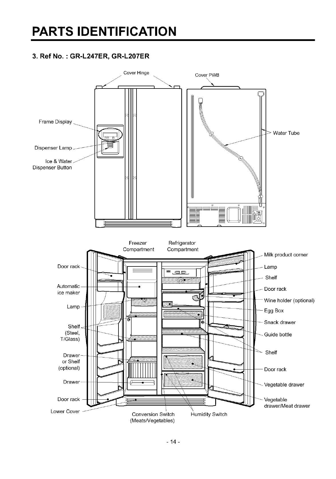
3. Ref No. : GR-L247ER, GR-L207ER
Frame Display
Dispenser Lamp
Dispenser Button
Cover Hinge Cover PWB
Door rack
ice maker
Shelf
(Steel,
TIGlass)
Drawer
or Shelf
(optional)
Freezer
Compartment
Refrigerator
Compartment f Milk product corner
Shelf
J Door rack
(optional)
Box
drawer
Shelf
rack
Lower Cover Conversion Switch
(MeatsNegetables)
Humidity Switch
drawer/Meat drawer
-14-
HOW TO INSTALL REFRIGERATOR
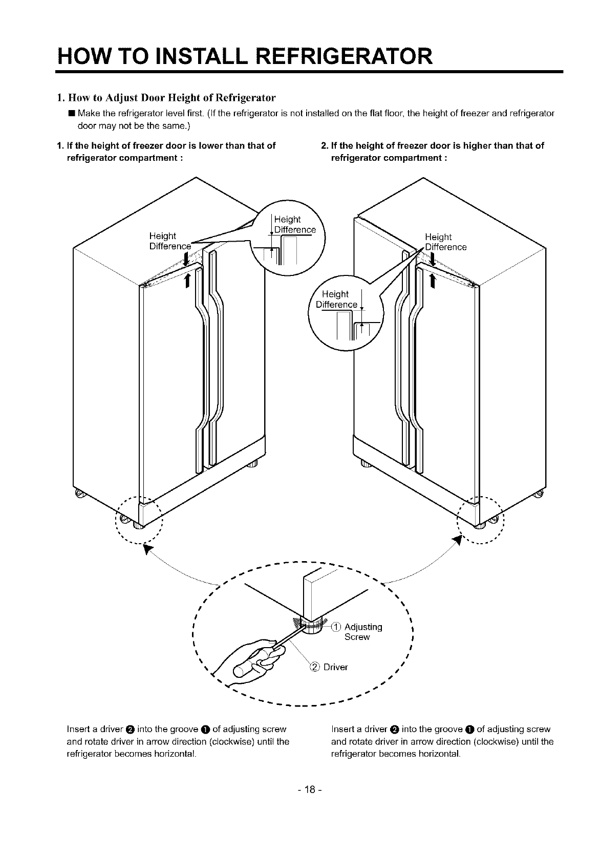
1. How to Adjust Door Height of Refrigerator
•Make the refrigerator levelfirst. (If the refrigerator is notinstalled on the flat floor, the height of freezer and refrigerator
door may not be the same.)
1. If the height of freezer door is lower than that of
refrigerator compartment :
2. If the height of freezer door is higher than that of
refrigerator compartment :
Height
Difference' Height
Difference
Insert a driver 0 into the groove Oof adjusting screw
and rotate driver in arrow direction (clockwise) until the
refrigerator becomes horizontal.
Insert a driver 0 into the groove O of adjusting screw
and rotate driver in arrow direction (clockwise) until the
refrigerator becomes horizontal.
-18-
HOW TO INSTALL REFRIGERATOR
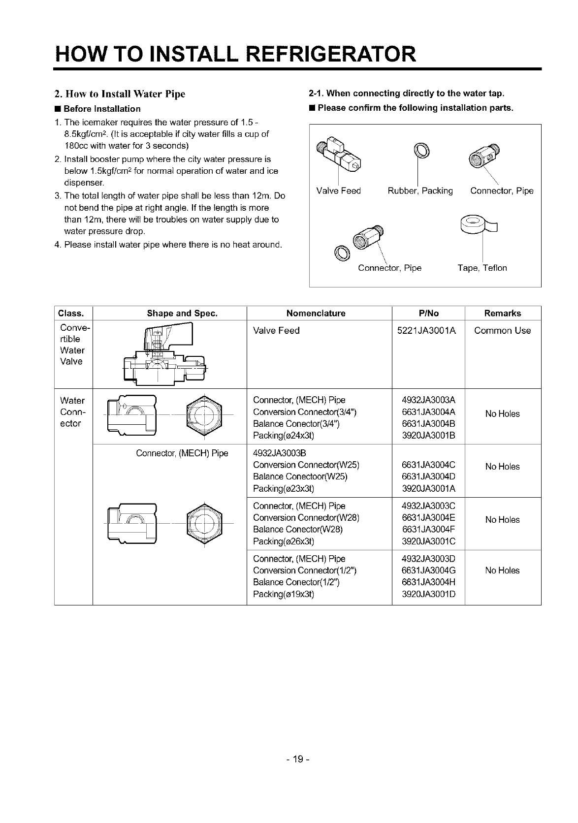
2. How to Install Water Pipe
•Before Installation
1. The icemaker requires the water pressure of 1.5
8.5kgf/cm 2. (It is acceptable if city water fills acup of
180cc with water for 3 seconds)
2. Install booster pump where the city water pressure is
below 1,5kgf/cm 2 for normal operation of water and ice
dispenser.
3. The total length of water pipe shall be less than 12m, Do
not bend the pipe at right angle. If the length is more
than 12m, there will be troubles on water supply due to
water pressure drop.
4. Please install water pipe where there is no heat around.
2-1. When connecting directly to the water tap.
•Please confirm the following installation parts,
Valve Feed Rubber, Packing Connector, Pipe
Connector, Pipe Tape, Teflon
Class,
Conve-
rtible
Water
Valve
Water
Conn-
ector
Shape and Spec.
Connector, (MECH) Pipe
Nomenclature
Valve Feed
Connector,(MECH) Pipe
ConversionConnector(3/4")
BalanceCenector(3/4")
Packing(e24x3t)
4932JA3003B
ConversionConnector(W25)
BalanceConectoor(W25)
Packing(e23x3t)
P/No
5221JA3001A
4932JA3003A
6631JA3004A
6631JA3004B
3920JA3001B
6631JA3004C
6631JA3004D
3920JA3001A
Remarks
Common Use
No Holes
No Holes
Connector,(MECH) Pipe 4932JA3003C
ConversionConnector(W28) 6631JA3004E No Holes
BalanceConector(W28) 6631JA3004F
Packing(e26x3t) 3920JA3001C
No Holes
Connector,(MECH) Pipe
ConversionConnector(I/2")
BalanceConector(1/2")
Packing(e19x3t)
4932JA3003D
6631JA3004G
6631JA3004H
3920JA3001D
-19-
HOW TO INSTALL REFRIGERATOR
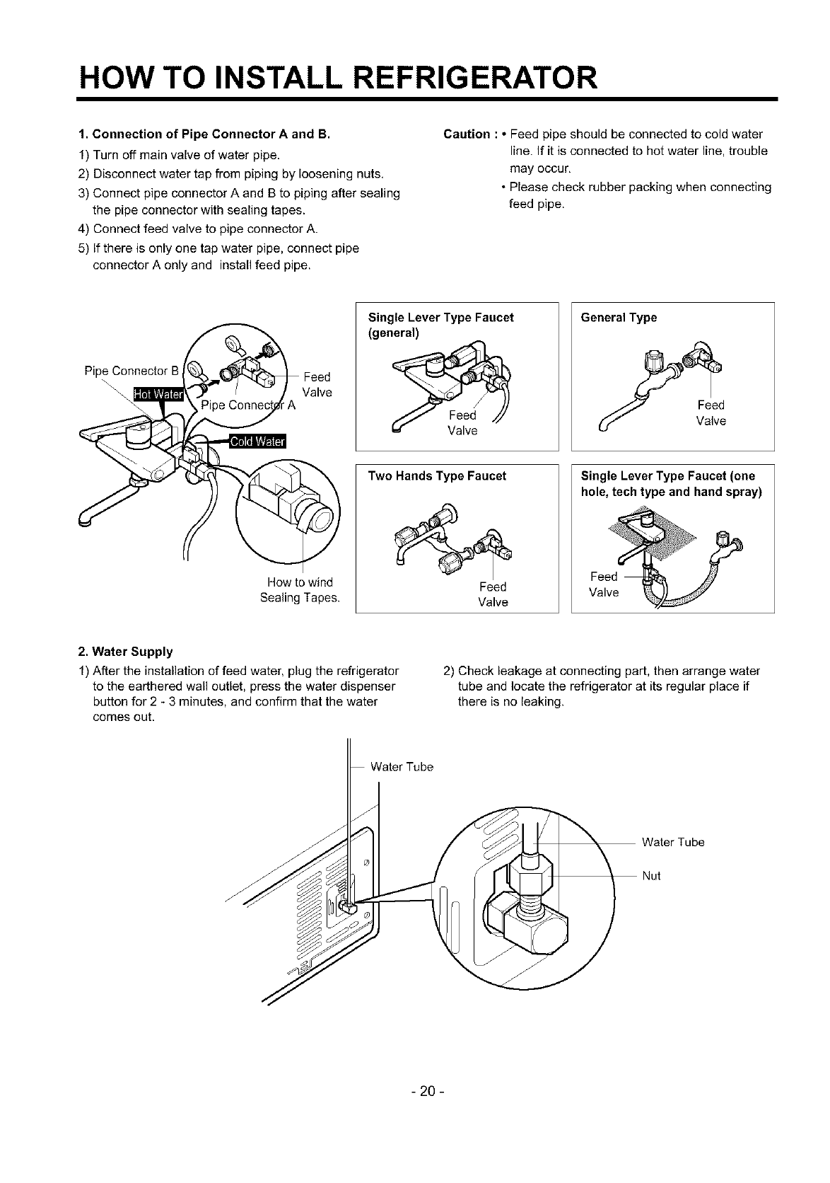
1. Connection of Pipe Connector A and B.
1) Turn off main valve of water pipe.
2) Disconnect water tap from piping by loosening nuts,
3) Connect pipe connector A and B to piping after sealing
the pipe connector with sealing tapes.
4) Connect feed valve to pipe connector A.
5) If there is only one tap water pipe, connect pipe
connector A only and install feed pipe.
Caution :•Feed pipe should be connected to cold water
line. If it is connected to hot water line, trouble
may occur,
• Please check rubber packing when connecting
feed pipe.
Pipe Connector B
\\ \Valve
How to wind
Sealing Tapes.
Single Lever Type Faucet
(general)
Two Hands Type Faucet
Feed
Valve
General Type
Single Lever Type Faucet (one
hole, tech type and hand spray)
Feed
Valve
2. Water Supply
1) After the installation of feed water, plug the refrigerator
to the earthered wall outlet, press the water dispenser
button for 2 - 3 minutes, and confirm that the water
comes out,
2) Check leakage at connecting part, then arrange water
tube and locate the refrigerator at its regular place if
there is no leaking.
Water Tube
f
Nut
- 20 -
HOW TO INSTALL REFRIGERATOR
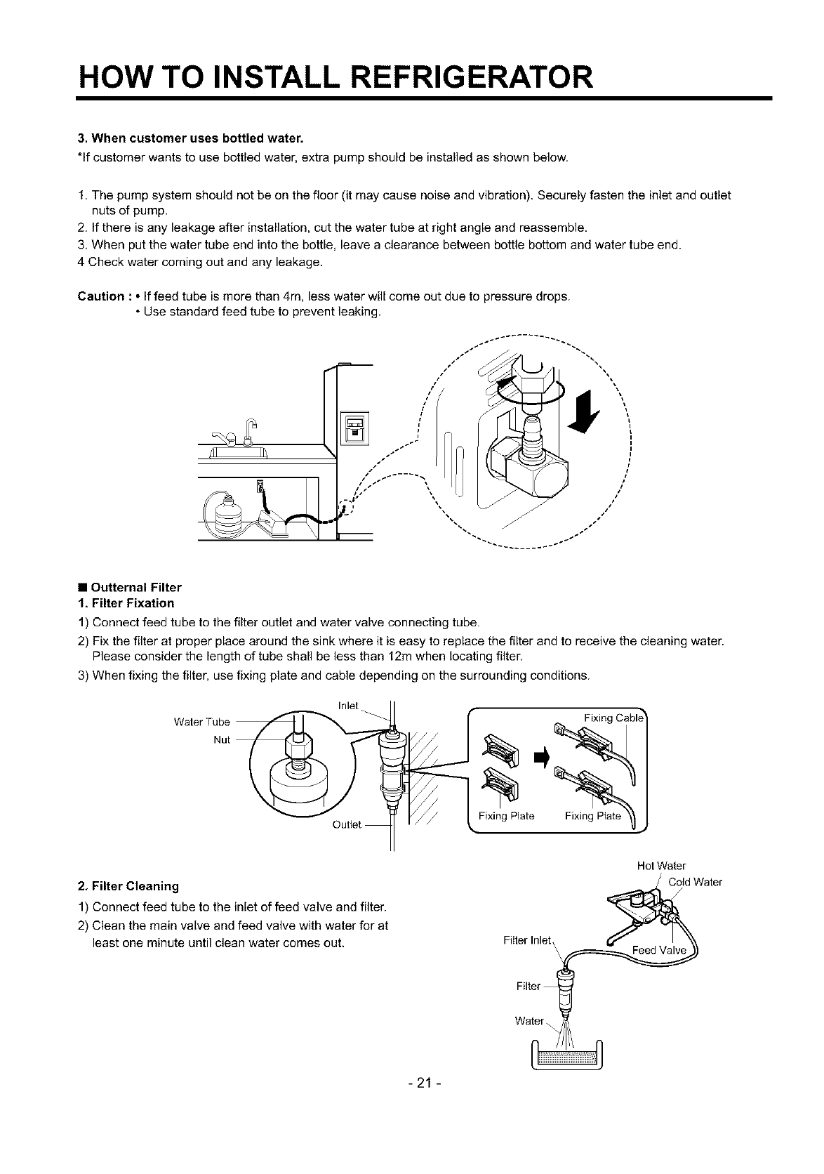
3. When customer uses bottled water.
*If customer wants to use bottled water, extra pump should be installed as shown below.
1. The pump system should not be on the floor (it may cause noise and vibration). Securely fasten the inlet and outlet
nuts of pump.
2. If there is any leakage after installation, cut the water tube at right angle and reassemble.
3, When put the water tube end into the bottle, leave a clearance between bottle bottom and water tube end.
4 Check water coming out and any leakage.
Caution :• If feed tube is more than 4m, less water will come out due to pressure drops.
• Use standard feed tube to prevent leaking.
•Outternal Filter
1, Filter Fixation
1) Connect feed tube to the filter outlet and water valve connecting tube.
2) Fix the filter at proper place around the sink where it is easy to replace the filter and to receive the cleaning water.
Please consider the length of tube shall be less than 12m when locating filter.
3) When fixing the filter, use fixing plate and cable depending on the surrounding conditions.
Water Tube
Nut
Inlet
FixingPlate
2. Filter Cleaning
1) Connect feed tube to the inlet of feed valve and filter.
2) Clean the main valve and feed valve with water for at
least one minute until clean water comes out. Filter Inlet,\
Hot Water
Cold Water
Feed Valve
Water
-21 -
HOW TO INSTALL REFRIGERATOR
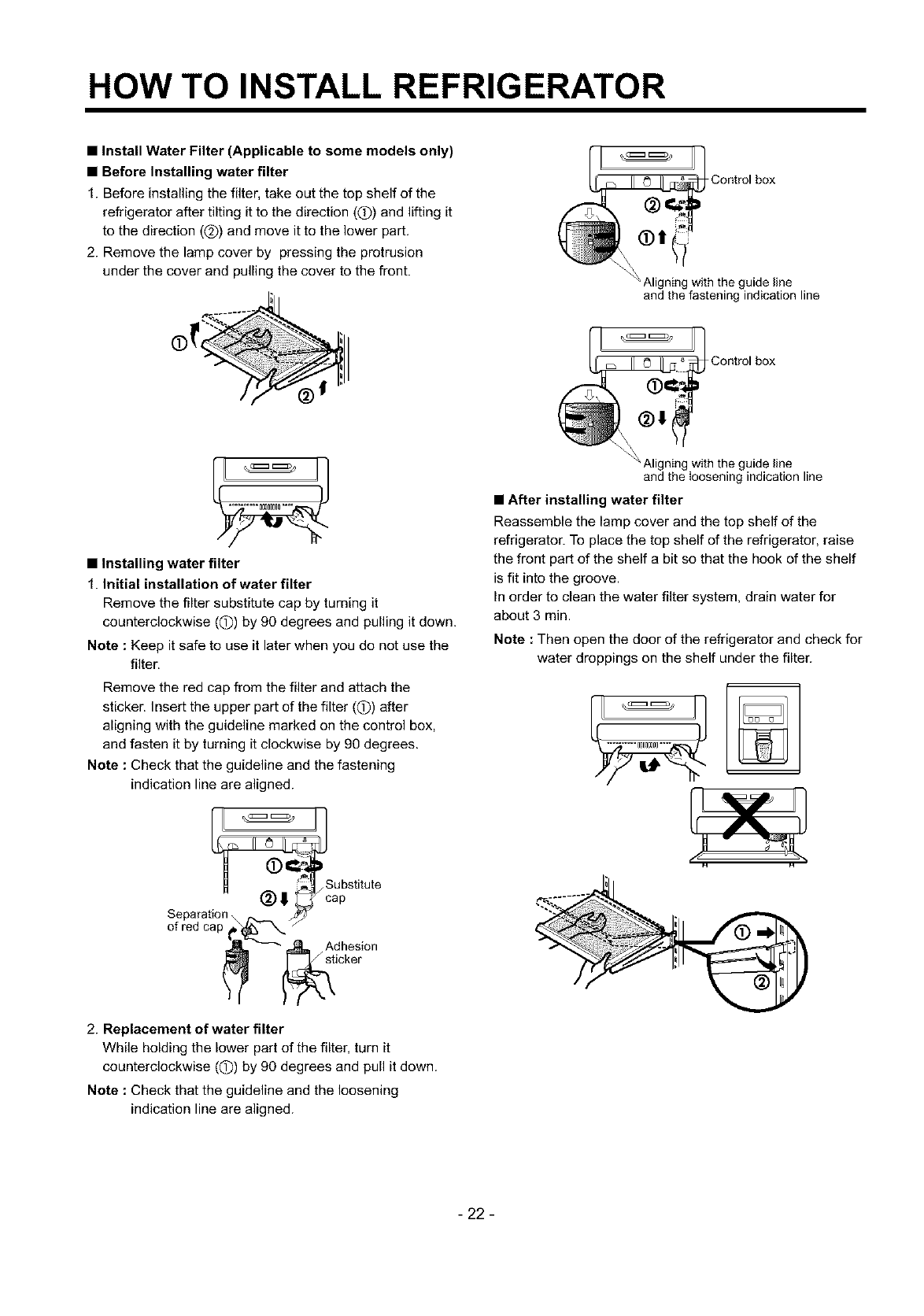
•Install Water Filter (Applicable to some models only)
•Before Installing water filter
1. Before installing the filter, take out the top shelf of the
refrigerator after tilting it to the direction (Q) and lifting it
to the direction (@) and move it to the lower part,
2. Remove the lamp cover by pressing the protrusion
under the cover and pulling the cover to the front.
IIl IIJ
•Installing water filter
1. Initial installation of water filter
Remove the filter substitute cap by turning it
counterclockwise ((D) by 90 degrees and pulling it down.
Note : Keep it safe to use it later when you do not use the
filter.
Remove the red cap from the filter and attach the
sticker. Insert the upper part of the filter ((!)) after
aligning with the guideline marked on the control box,
and fasten it by turning it clockwise by 90 degrees.
Note : Check that the guideline and the fastening
indication line are aligned.
Substitute
ap
Separation _ _
of red cap____ _Aidchkes'i°n
2. Replacement of water filter
While holding the lower part of the filter, turn it
counterclockwise ((D) by 90 degrees and pull it down.
Note : Check that the guideline and the loosening
indication line are aligned.
Control box
Aligning with the guide line
and the fastening indication line
[11 q Contro,box
_'J_ Aligni_lgwith the guide line
and the loosening indication line
•After installing water filter
Reassemble the lamp cover and the top shelf of the
refrigerator. To place the top shelf of the refrigerator, raise
the front part of the shelf a bit so that the hook of the shelf
is fit into the groove.
In order to clean the water filter system, drain water for
about 3 min.
Note : Then open the door of the refrigerator and check for
water droppings on the shelf under the filter.
- 22 -
HOW TO INSTALL REFRIGERATOR
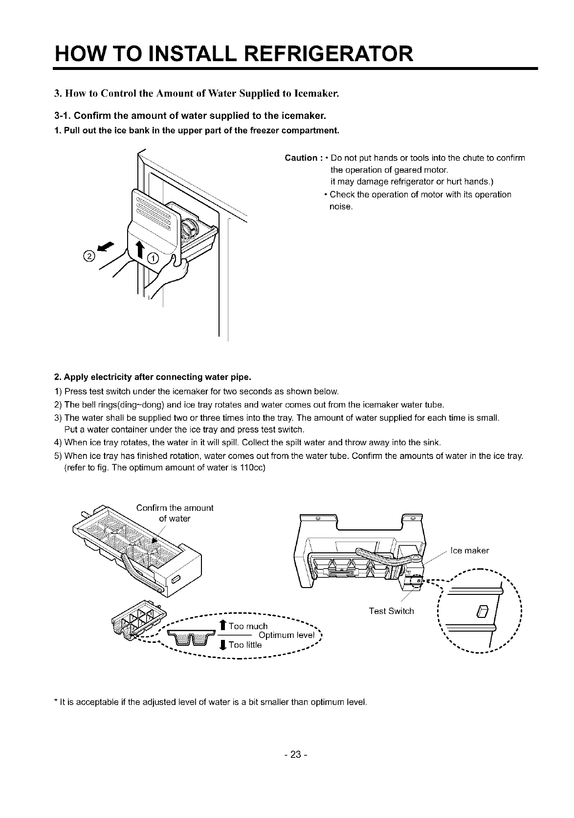
3. How to Control the Amount of Water Supplied to lcemaker.
3-1. Confirm the amount of water supplied to the icemaker.
1, Pull out the ice bank in the upper part of the freezer compartment.
Caution : • Do not put hands or tools into the chute to confirm
the operation of geared motor.
it may damage refrigerator or hurt hands.)
• Check the operation of motor with its operation
noise.
2. Apply electricity after connecting water pipe.
1) Press test switch under the icemaker for two seconds as shown below.
2) The bell rings(ding-dong) and ice tray rotates and water comes out from the icemaker water tube.
3) The water shall be supplied two or three times into the tray. The amount of water supplied for each time is small.
Put a water container under the ice tray and press test switch.
4) When ice tray rotates, the water in it will spill. Collect the spilt water and throw away into the sink.
5) When ice tray has finished rotation, water comes out from the water tube. Confirm the amounts of water in the ice tray.
(refer to fig. The optimum amount of water is 110cc)
Confirm the amount
of water
Too much -.
_-" -- Optimum level )
-.. -- _oo _lL_e ,,
Test Switch
Pq
ice maker
*it is acceptable if the adjusted level of water is a bit smaller than optimum level.
- 23 -
HOW TO INSTALL REFRIGERATOR
3-2. Control the amount of water supplied to the
icemaker.
Caution : • Please unplug the power cord from the wall
outlet and wait for more than three minutes
before disconnecting PWB cover as 310V is
applied in the control panel.
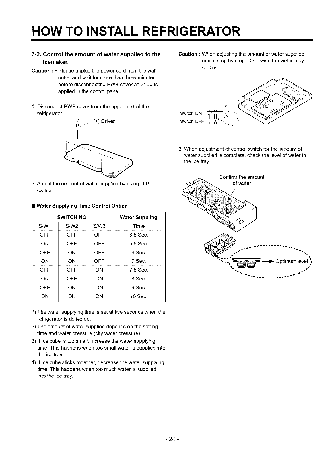
1. Disconnect PWB cover from the upper part of the
refrigerator.
(+) Driver
2. Adjust the amount of water supplied by using DIP
switch.
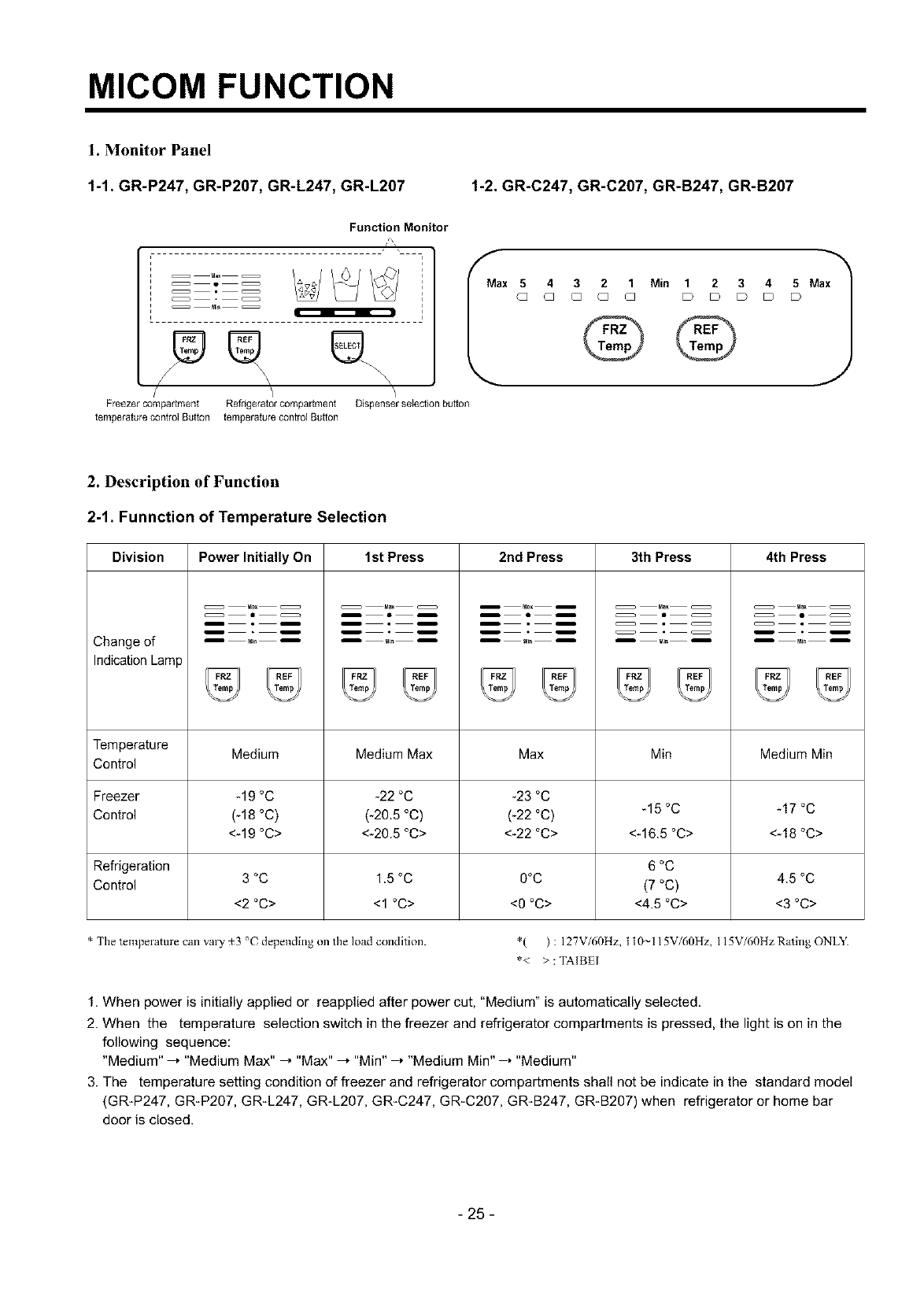
Caution :When adjusting the amount of water supplied,
adjust step by step. Otherwise the water may
spill over.
Switch ON
Switch OFF
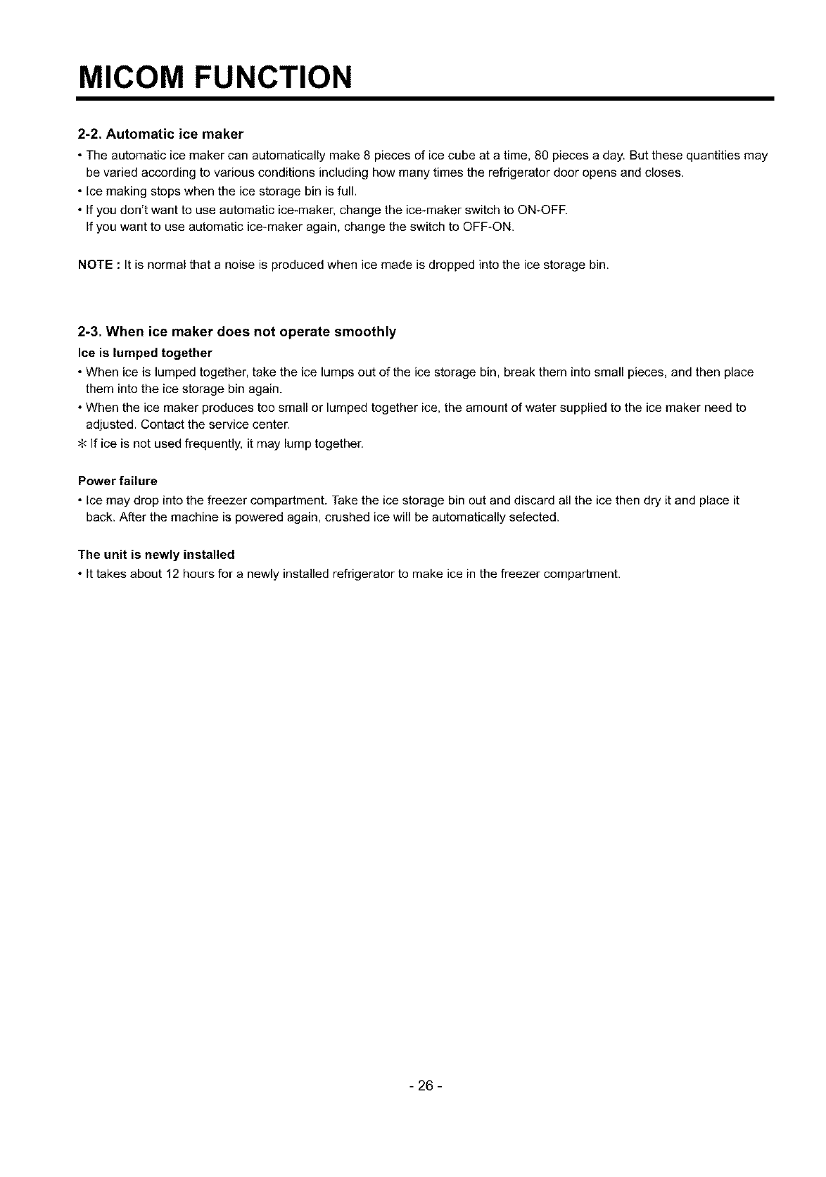
3. When adjustment of control switch for the amount of
water supplied is complete, check the level of water in
the ice tray.
Confirm the amount
of water
•Water Supplying Time Control Option
SWITCH NO Water Suppling
StWl S/W2 S/W3 Time
OFF OFF OFF 6.5 Sec.
ON OFF OFF 5.5 Sec.
OFF ON OFF 6 Sec.
ON ON OFF 7 Sec.
OFF OFF ON 7.5 Sec.
ON OFF ON 8 Sec.
OFF ON ON 9 Sec.
ON ON ON 10 Sec.
"--~ _ Optimum level
1) The water supplying time is set at five seconds when the
refrigerator is delivered.
2) The amount of water supplied depends on the setting
time and water pressure (city water pressure).
3) If ice cube is too small, increase the water supplying
time. This happens when too small water is supplied into
the ice tray.
4) If ice cube sticks together, decrease the water supplying
time. This happens when too much water is supplied
into the ice tray.
- 24 -
MICOM FUNCTION
1. Monitor Panel
1-1. GR-P247, GR-P207, GR-L247, GR-L207 1-2. GR-C247, GR-C207, GR-B247, GR-B207
Function Monitor
®® ®..
/\ \_\
Freezer compartment Refrigerator compartment
temperature control Button temperature control Button
ax 5
G
Dispenser selection button
4
Q
3 2 1 Min 1 2 3 45 Max
Q Q Q D D D D D
J
2. Description of Function
2-1. Funnction of Temperature Selection
Division
Change of
Indication Lamp
Power Initially On 1st Press 2nd Press 3th Press 4th Press
Temperature Medium Medium Max Max Min Medium Min
Control
Freezer -19 °C -22 °C -23 °C
Control (-18 °C) (-20.5 °C) (-22 °C) -15 °C -17 °C
<-19 °C> <-20.5 °C> <-22 °C> <-16.5 °C> <-18 °C>
Refrigeration 6 °C
Control 3 °C 1.5 °C O°C (7 °C) 4.5 °C
<2 °C> <1 °C> <O °C> <4.5 °C> <3 °C>
* The temperature call valy _3 °( depending on tile load condition. *( ) : 127V/60Hz, t t0~115V/60Hz, 115V/60HzRating ONLY.
*< >: TAIBEI
1. When power is initially applied or reapplied after power cut, "Medium" is automatically selected.
2. When the temperature selection switch in the freezer and refrigerator compartments is pressed, the light is on in the
following sequence:
"Medium" ,"Medium Max" , "Max" .'"Min" , "Medium Min" , "Medium"
3. The temperature setting condition of freezer and refrigerator compartments shall not be indicate in the standard model
(GRIP247, GRIP207, GR_L247, GR-L207, GR-C247, GR_C207, GR-B247, GR-B207) when refrigerator or home bar
door is closed.
- 25-
MICOM FUNCTION
2-2. Automatic ice maker
• The automatic ice maker can automatically make 8 pieces of ice cube at a time, 80 pieces a day. But these quantities may
be varied according to various conditions including how many times the refrigerator door opens and closes.
• Ice making stops when the ice storage bin is full.
• If you don't want to use automatic ice-maker, change the ice-maker switch to ON-OFF.
If you want to use automatic ice-maker again, change the switch to OFF-ON.
NOTE :It is normal that a noise is produced when ice made is dropped into the ice storage bin.
2-3. When ice maker does not operate smoothly
Ice is lumped together
• When ice is lumped together, take the ice lumps out of the ice storage bin, break them into small pieces, and then place
them into the ice storage bin again.
• When the ice maker produces too small or lumped together ice, the amount of water supplied to the ice maker need to
adjusted. Contact the service center.
;{-"If ice is not used frequently, it may lump together.
Power failure
• Ice may drop into the freezer compartment. Take the ice storage bin out and discard all the ice then dry it and place it
back. After the machine is powered again, crushed ice will be automatically selected.
The unit is newly installed
• It takes about 12 hours for a newly installed refrigerator to make ice in the freezer compartment.
- 26 -
MICOM FUNCTION
2-4. Control of variable type of freezing room fan
1. To increase cooling speed and load response speed, MICOM variably controls freezing room fan motor at the high speed
of RPM and standard RPM.
2. MICOM only operates in the input of initial power or special freezing operation or load response operation for the high
speed of RPM and operates in the standard RPM in other general operation,
3. If opening doors of freezing /cold storage room or home bar while fan motor in the freezing room operates, the freezing
room fan motor normally operates (If being operated in the high speed of RPM, it converts operation to the standard
RPM). However, if opening doors of freezing room or home bar, the freezing room fan motor stops.
4. As for monitoring of BLDC fan motor error in the freezing room, MICOM immediately stops the fan motor by determining
that the BLDC fan motor is locked or poor if there would be position signal for more than 65 seconds at the BLDC motor.
Then it displays failure (refer to failure diagnosis function table) at the display part of refrigerator, performs re-operation in
the cycle of 30 minutes. If normal operation is performed, poor status is released and refrigerator returns to the initial
status (reset).
2-5. Control of M/C room fan motor
1. The M/C room fan motor performs ONIOFF control by linking with the COMP.
2. It controls at the single RPM without varying RPM.
3. Failure sensing method is same as in fan motor of freezing fan motor (refer to failure diagnosis function table for failure
display).
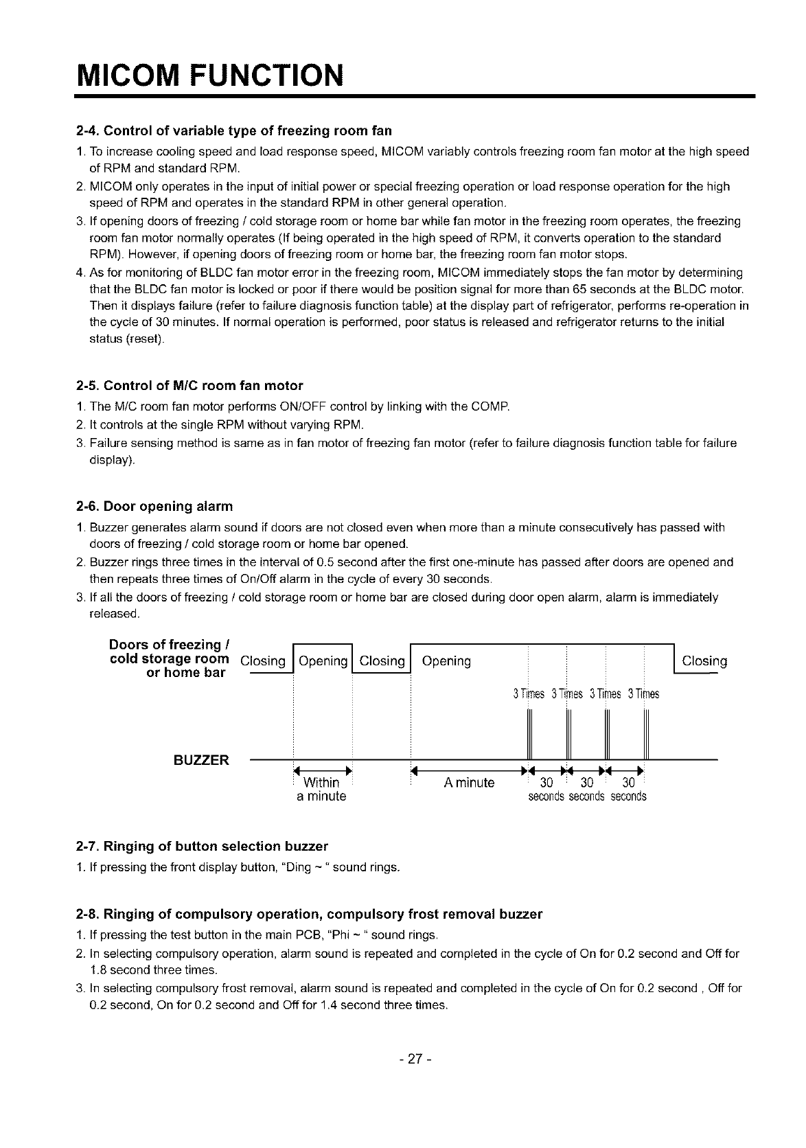
2-6. Door opening alarm
1. Buzzer generates alarm sound if doors are not closed even when more than a minute consecutively has passed with
doors of freezing /cold storage room or home bar opened,
2. Buzzer rings three times in the interval of 0.5 second after the first one-minute has passed after doors are opened and
then repeats three times of On/Off alarm in the cycle of every 30 seconds.
3. If all the doors of freezing /cold storage room or home bar are closed during door open alarm, alarm is immediately
released.
Doors of freezing /r_l i
cold storage room C_Openin_ Opening
or home bar I Closing
BUZZER
H:_
Within A minute
a minute
3Times3Times3Times3Times
: 30 i 30 i 30
secondssecondsseconds
2-7. Ringing of button selection buzzer
1. If pressing the front display button, "Ding -" sound rings.
2-8. Ringing of compulsory operation, compulsory frost removal buzzer
1. If pressing the test button in the main PCB, "Phi -" sound rings.
2. In selecting compulsory operation, alarm sound is repeated and completed in the cycle of On for 0.2 second and Off for
1.8 second three times.
3. In selecting compulsory frost removal, alarm sound is repeated and completed in the cycle of On for 0.2 second, Off for
0.2 second, On for 0.2 second and Off for 1.4 second three times.
- 27-
MICOM FUNCTION
2-9. Frost removal function
1. Frost removal is performed whenever total operation time of compressor becomes 7 - 7.5 hour.
2. In providing initial power (or returning power failure), frost removal starts whenever total operation time of compressor
becomes 4 - 4.5 hour.
3. Frost removal is completed if temperature of a frost removal sensor becomes more than 5°C after starting frost removal.
Poor frost removal is not displaced if it does not arrive at 5°C even if two hours have passed after starting frost removal.
4. No removal is done if frost removal sensor becomes poor (snapping or short-circuit).
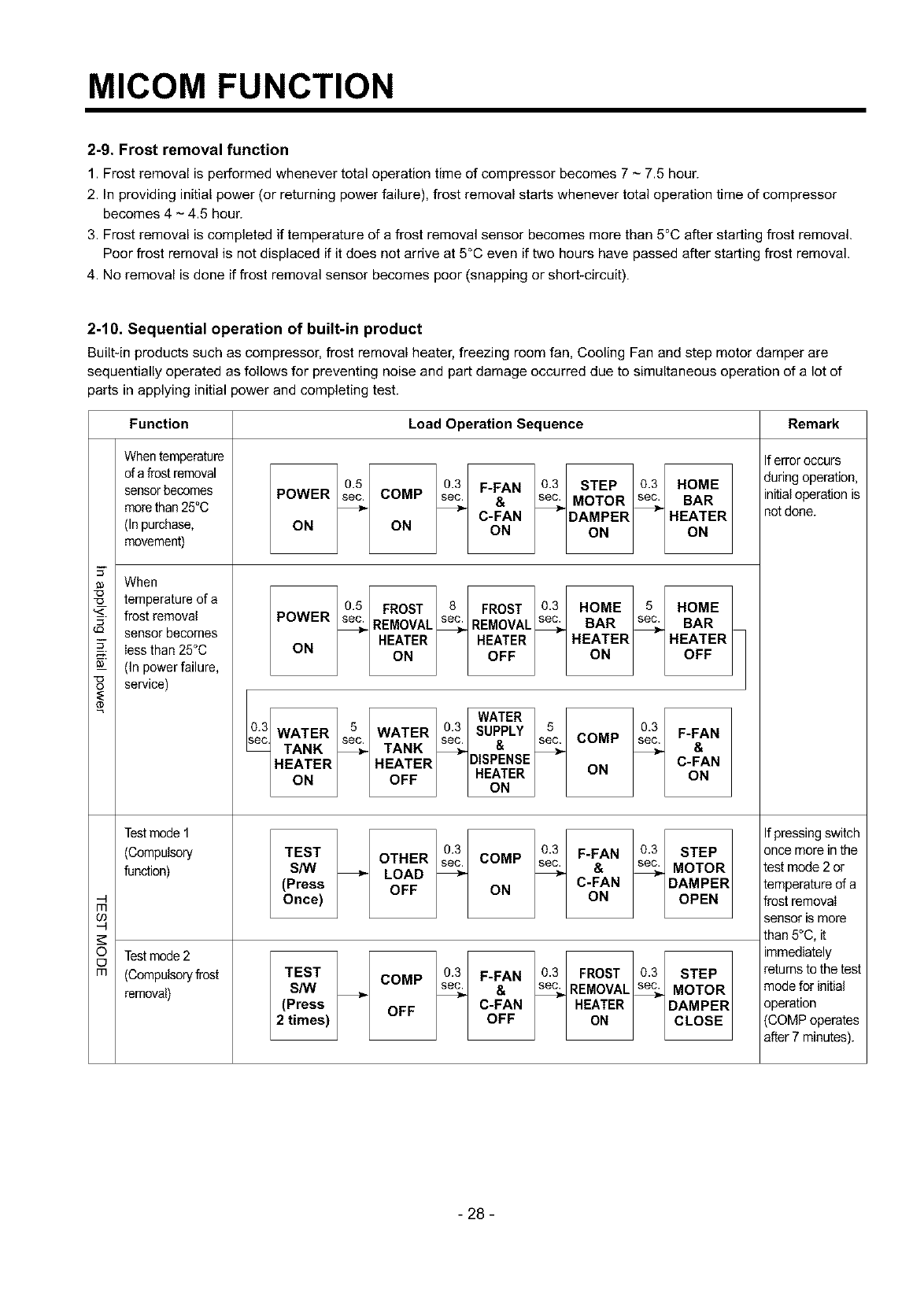
2-10. Sequential operation of built-in product
Built-in products such as compressor, frost removal heater, freezing room fan, Cooling Fan and step motor damper are
sequentially operated as follows for preventing noise and part damage occurred due to simultaneous operation of a lot of
parts in applying initial power and completing test.
Function Load Operation Sequence Remark
When temperature
of a frost removal
sensorbecomes
morethan 25°0
(In purchase,
movement)
When
__ temperature of a
"_- frost removal
sensor becomes
Iess than 25°0
_-- (In power failure,
service)
e
m
o
m
Test mode 1
(Compulsory
function)
Test mode2
(Compulsoryfrost
removal)
0.5 0.3 F-FAN 03 STEP 03 HOME
POWER sec COMP sec &sec MOTOR sec BAR
C-FAN DAMPER HEATER
ON ON ON ON ON
05 FROST 8FROST 03 HOME 5HOME
POWER sec REMOVAL sec REMOVAL sec BAR sec BAR
HEATER HEATER HEATER HEATER
ON ON OFF ON OFF
WATER
03 WATER 5 WATER 03 SUPPLY 5 03 F-FAN
sec. sec. &sec. COMP sec.
_ec TANK _TANK _ _ _ &
HEATER HEATER DISPENSE C-FAN
ON OFF HEATER ON ON
ON
0.3 03 F-FAN 03 STEP
TEST OTHER sec COMP sec &sec MOTOR
S/W _ LOAD _ _
(Press OFF ON C-FAN DAMPER
Once) ON OPEN
0.3 F-FAN 0.3 FROST 0.3 STEP
TEST COMP sec. sec.
S/W _ _ &_REMOVAL%MOTOR
(Press OFF C-FAN HEATER DAMPER
2 times) OFF ON CLOSE
If erroroccurs
during operation,
initialoperation is
notdone.
If pressing switch
once more in the
test mode 2 or
temperature of a
frost removaI
sensor ismore
than 5°C, it
immediately
returns to the test
mode for initial
operation
(COMP operates
after 7 minutes).
- 28 -
MICOM FUNCTION
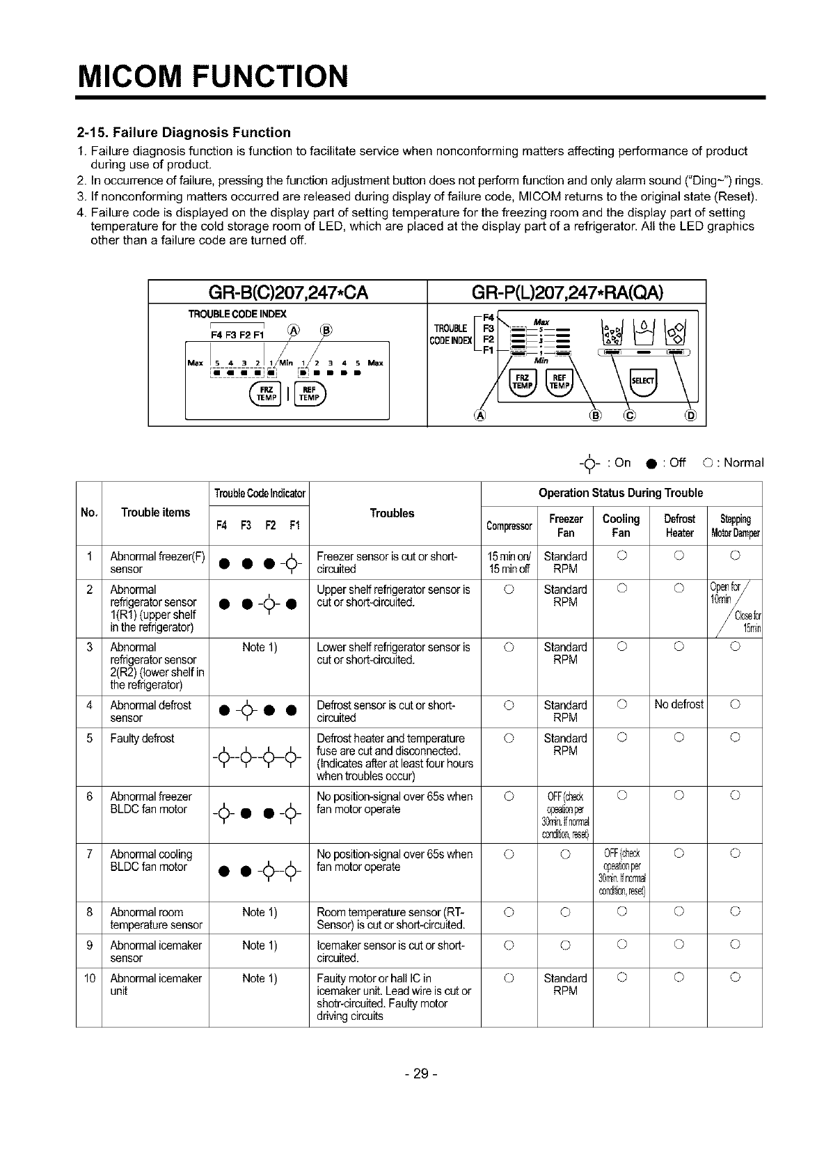
2-15. Failure Diagnosis Function
1. Failure diagnosis function is function to facilitate service when nonconforming matters affecting performance of product
during use of product.
2. In occurrence of failure, pressing the function adjustment button does not perform function and only alarm sound ("Ding-") rings.
3. If nonconforming matters occurred are released during display of failure code, MICOM returns to the original state (Reset).
4. Failure code is displayed on the display part of setting temperature for the freezing room and the display part of setting
temperature for the cold storage room of LED, which are placed at the display part of a refrigerator. All the LED graphics
other than a failure code are turned off.
GR-B(C)207,247*CA
TROUBLE CODE INDEX
r 7 K_7
F4 F3 F2 F1
Max !S 4 3 2]l_M_n 1_2 _4N Max
LI i i mllmj _l • B B
GR-P(L)207,247.RA(O.A)
I"
-_- :On • :Off ©:Normal
TroubleCodeIndicator Operation Status DuringTrouble
No, Trouble items Troubles Freezer Cooling Defrost Stepping
F4 F3 F2 Ff Compressor Fan Fan Heater MotorDamper
1 sensorAbn°rmalfreezer(F) • • •-_6- circuitedFreezersensoris cut or short- 115minoff5rainon/ StandardRPM © O ©
2 Abnormal Uppershelf refrigeratorsensor is O Standard O O Openfcr/
refrigeratorsensor • •-¢-
I(Rf) (uppershelf • cut orshort-circuited. RPM
in the refrigerator)
3 Abnormal Note 1) Lowershelf refrigeratorsensor is © Standard © © ©
refrigeratorsensor cut orshort-circuited. RPM
2(R2)(lower shelfin
the refrigerator)
4 Abnormaldefrost • _A_ • • Defrostsensoris cut or short- © Standard © No defrost ©
sensor Y circuited RPM
5 Faultydefrost Defrostheater andtemperature © Standard © © ©
_¢__¢___¢_ fuse are cut and disconnected. RPM
(Indicatesafter at leastfour hours
when troublesoccur)
6 Abnormalfreezer No position-signalover 65s when O 0FF(ch_ O O O
BLDCfan motor _¢_ • • _¢_ fan motor operate @eat;®per
30mi_7,_fn0rmal
c0ndr_®,reset}
7 Abnormalcooling No position-signalover 65s when © O 0FF(ch_ O ©
BLDCfan motor • • _1(_¢_ fan motor operate @eat;®per
30mi_7,_fn0rmal
®ndr_®,reset}
8 Abnormalroom Note 1) Roomtemperaturesensor(RT- O O O O O
temperaturesensor Sensor) is cat or short-circuited.
9 Abnormalicemaker Note 1) Icemakersensoriscut orshort- © O O O O
sensor circuited.
10 Abnormalicemaker Note 1) Faultymotor or hall ICin © Standard © © ©
unit icemakerunit.Leadwire is cut or RPM
shotr-circuited.Faulty motor
driving circuits
- 29 -
MICOM FUNCTION
Note1) The abnormality of RT-Sensor, R2-Sensor Icemaker Unit, and Icemaker-Sensor is not indicated in trouble code but it
is indicated when checking LED (when pressing both freezer temperature control button and refrigerator temperature
control button for more than 1 second at the same time).
RT-Sensor
R2-Sensor
Icemaker Unit
Icemaker Sensor
Normal : (_ LED on,
Normal : _) LED on,
Normal : (_ LED on,
Normal : _) LED on,
Abnormal : (_) LED Off.
Abnormal : (_ LED Off.
Abnormal : (_ LED Off,
Abnormal : (_) LED Off.
The rest of LEDs
are all on.
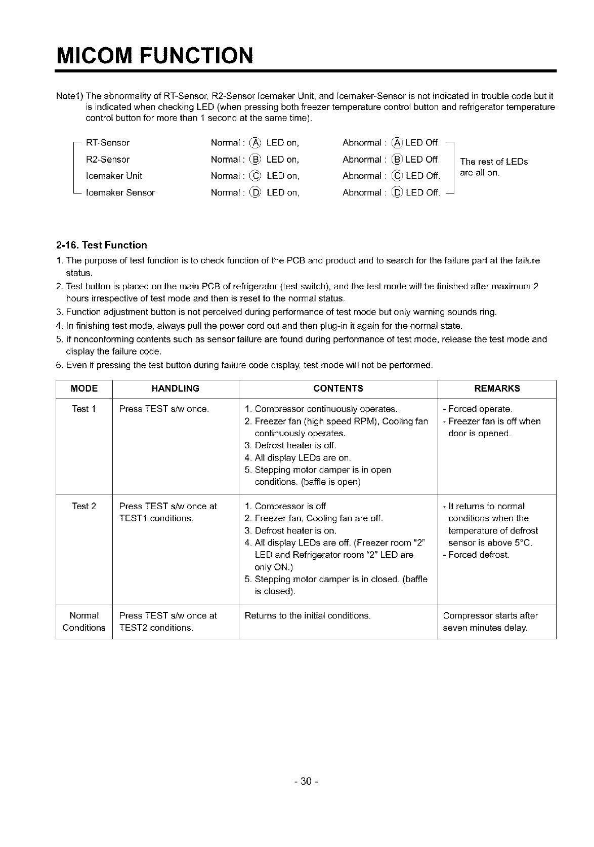
2-16. Test Function
1. The purpose of test function is to check function of the PCB and product and to search for the failure part at the failure
status.
2. Test button is placed on the main PCB of refrigerator (test switch), and the test mode will be finished after maximum 2
hours irrespective of test mode and then is reset to the normal status.
3. Function adjustment button is net perceived during performance of test mode but only warning sounds ring.
4. In finishing test mode, always pull the power cord out and then plug-in it again for the normal state.
5. If nonconforming contents such as sensor failure are found during performance of test mode, release the test mode and
display the failure code.
6. Even if pressing the test button during failure code display, test mode will not be performed.
MODE
Test 1
Test 2
HANDLING
Press TEST s/w once.
Press TEST s/w once at
TEST1 conditions.
CONTENTS
1. Compressor continuously operates.
2. Freezer fan (high speed RPM), Cooling fan
continuously operates.
3. Defrost heater is off,
4. All display LEDs are on.
5. Stepping motor damper is in open
conditions. (baffle is open)
1. Compressor is off
2. Freezer fan, Cooling fan are off.
3. Defrost heater is on.
4. All display LEDs are off. (Freezer room "2"
LED and Refrigerator room "2" LED are
only ON.)
5. Stepping motor damper is in closed. (baffle
is closed).
REMARKS
- Forced operate.
- Freezer fan is off when
door is opened.
- It returns to normal
conditions when the
temperature of defrost
sensor is above 5°C.
- Forced defrost.
Normal Press TEST s/w once at Returns to the initial conditions. Compressor starts after
Conditions TEST2 conditions, seven minutes delay.
- 30 -
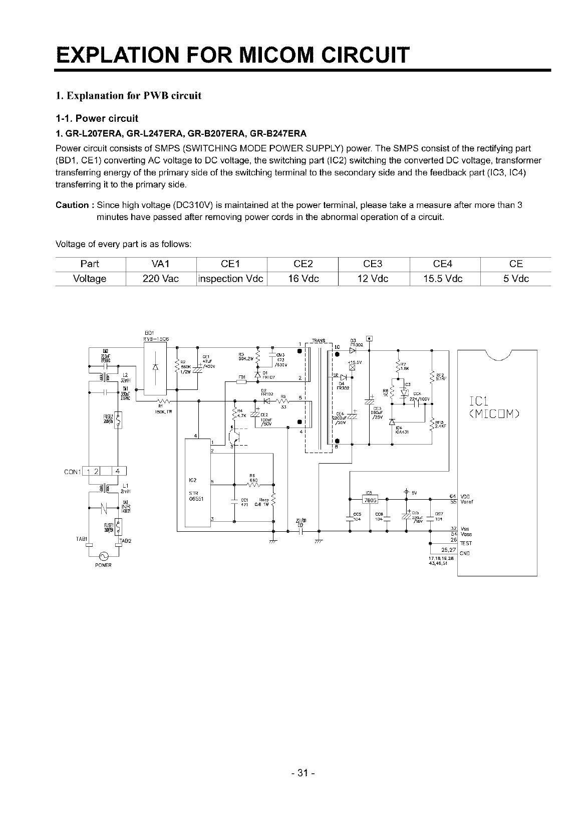
EXPLATION FOR MICOM CIRCUIT
1. Explanation for PWB circuit
%1. Power circuit
1, GR-L207ERA, GR-L247ERA, GR-B207ERA, GR-B247ERA
Power circuit consists of SMPS (SWITCHING MODE POWER SUPPLY) power. The SMPS consist of the rectifying part
(BD1, CE1) converting AC voltage to DC voltage, the switching part (IC2) switching the converted DC voltage, transformer
transferring energy of the primary side of the switching terminal to the secondary side and the feedback part (IC3, IC4)
transferring it to the primary side.
Caution :Since high voltage (DC310V) is maintained at the power terminal, please take a measure after more than 3
minutes have passed after removing power cords in the abnormal operation of acircuit.
Voltage of every part is as follows:
Part VA1 CE1 Vdc CE2
Voltage 220 Vac inspection 16 Vdc
CE3 CE4 CE
12 Vdc 15.5 Vdc 5 Vdc
CON1
BDI
RVB 1506
R1
15DK,1W
L1
VAI
_INR
pOWER
÷
]RANS D3
1 F • I0 _3o2
/
FBI 2 I_ ,>>RF2KF
FRI02 R5 I K % ;CO+
I<_ 5 i +2 4 00v
I_ +33 I+CE3
<,R4 C 2IBS(]uF
"_7K IOOUF •I/2_V R_KF
4C7cl] 08RQlC_<" u - - 5£
43,48,51
IC1
(MICOM)
VDO
V_]ref
Vss
Wss
_ST
GNO
-31 -
EXPLATION FOR MICOM CIRCUIT
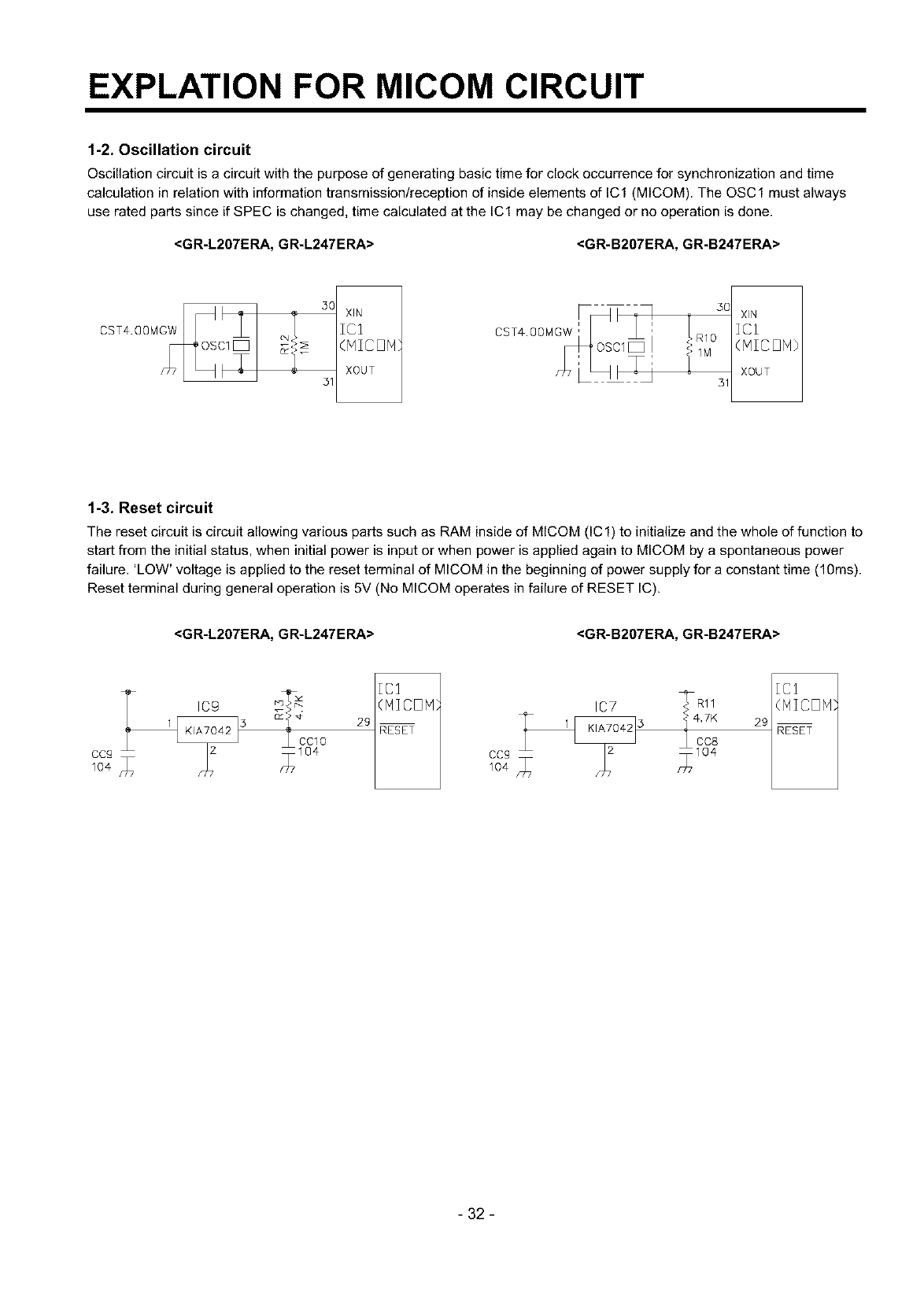
1-2. Oscillation circuit
Oscillation circuit is a circuit with the purpose of generating basic time for clock occurrence for synchronization and time
calculation in relation with information transmission/reception of inside elements of IC1 (MICOM). The OSC1 must always
use rated parts since if SPEC is changed, time calculated at the IC1 may be changed or no operation is done.
<GR-L207ERA, GR-L247ERA> <GR-B207ERA, GR-B247ERA>
50 XIN 30
(MICON o
XOUT
31 31
XIN
ICI
(HICON)
XOUT
1-3. Reset circuit
The reset circuit is circuit allowing various parts such as RAM inside of MICOM (IC1) to initialize and the whole of function to
start from the initial status, when initial power is input or when power is applied again to MICOM by aspontaneous power
failure. 'LOW' voltage is applied to the reset terminal of MICOM in the beginning of power supply for a constant time (10ms).
Reset terminal during general operation is 5V (No MICOM operates in failure of RESET IC).
<GR-L207ERA, GR-L247ERA> <GR-B207ERA, GR-B247ERA>
Tcg [C1 _ml [Cl
_T_ (MICOP1} IC7 (NICON
_" 4_4,7K 29
_3 t CCIO 29 RESET •CC8 RESET
104CCg f717104 m[7104
- 32 -
EXPLATION FOR MICOM CIRCUIT
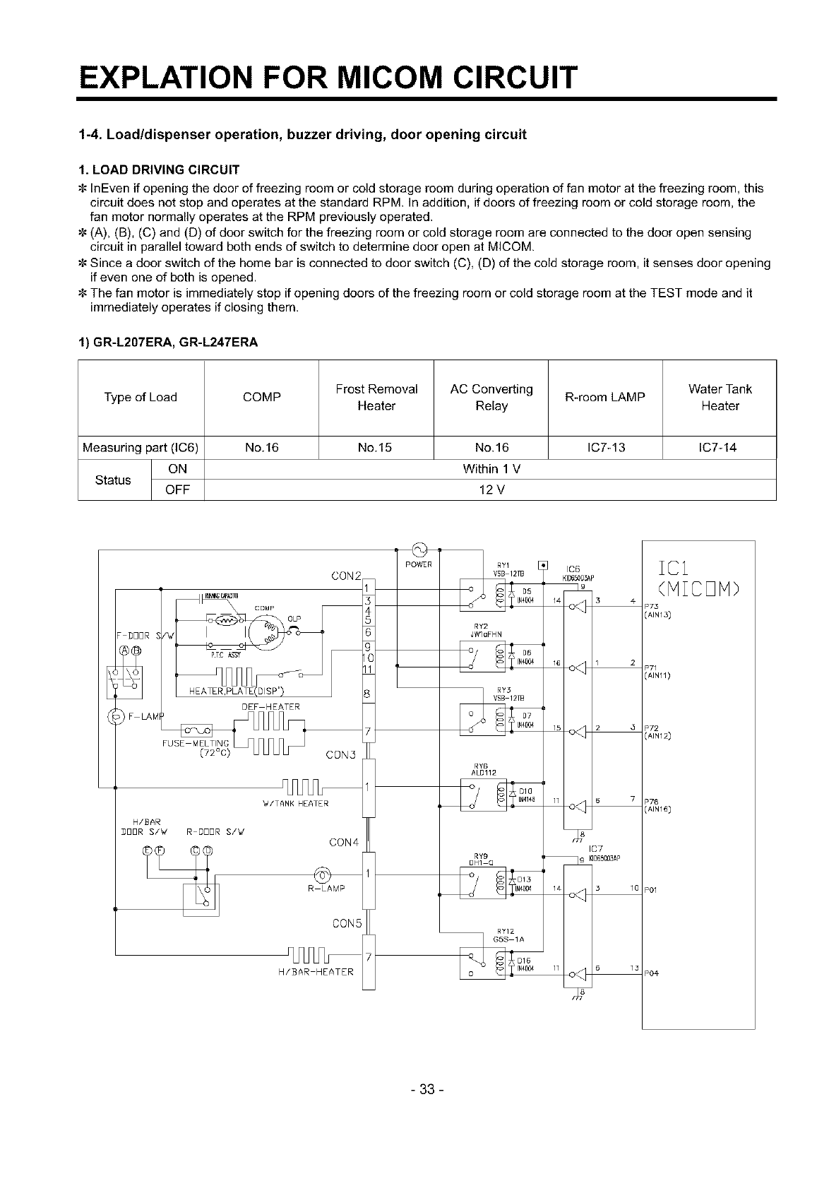
1-4. Load/dispenser operation, buzzer driving, door opening circuit
1. LOAD DRIVING CIRCUIT
InEven if opening the door of freezing room or cold storage room during operation of fan motor at the freezing room, this
circuit does not stop and operates at the standard RPM. In addition, if doors of freezing room or cold storage room, the
fan motor normally operates at the RPM previously operated.
(A), (B), (C) and (D) of door switch for the freezing room or cold storage room are connected to the door open sensing
circuit in parallel toward both ends of switch to determine door open at MICOM.
Since a door switch of the home bar is connected to door switch (C), (D) of the cold storage room, it senses door opening
if even one of both is opened.
The fan motor is immediately stop if opening doors of the freezing room or cold storage room at the TEST mode and it
immediately operates if closing them.
1) GR-L207ERA, GR-L247ERA
Frost Removal AC Converting Water Tank
Type of Load COMP R-room LAMP
Heater Relay Heater
Measuring part (IC6) No. 16 No. 15 No. 16 IC7-13 IC7-14
ON Within 1 V
Status OFF 12 V
COMP
DDDR S _7
PTC ASST
DEF HEATER
CON2
CON5
_4/TANK HEATER
H/BAR
DDDR S/'d R I]DDR S/'d CON4
R LAMP
CON5
H/BAR HEATER
pOWER
RY2
JWlaFHN
RY6
ALD112
RY9
OH] Q
D]3
RY12
_G5S ]A
D16
IC7
_k_OO3AP
IC1
(HICDH)
P73
(AIN13)
P72
(AIN12)
P76
(AIN16)
P01
PO#
- 33 -
EXPLATION FOR MICOM CIRCUIT
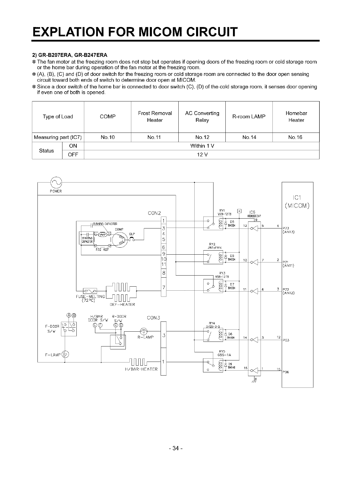
2) GR-B207ERA, GR-B247ERA
The fan motor at the freezing room does not stop but operates if opening doors of the freezing room or cold storage room
or the home bar during operation of the fan motor at the freezing room.
(A), (B), (C) and (D) of door switch for the freezing room or cold storage room are connected to the door open sensing
circuit toward both ends of switch to determine door open at MICOM
Since a door switch of the home bar is connected to door switch (C), (D) of the cold storage room, it senses door opening
if even one of both is opened.
Frost Removal AC Converting Homebar
Type of Load COMP R-room LAMP
Heater Relay Heater
Measuring part (IC7) No.10 No.ll No.12 No.14 No.16
ON Within 1 V
Status OFF 12 V
POWER
F LAMP 4
CON2
_UNNNG CAPADFOR
COMP
P.TC AS_
DEF HEATER
H/B4R R _UUR CON3
BBBR S/W S/W
P03
P06
IC1
- 34 -
EXPLATION FOR MICOM CIRCUIT
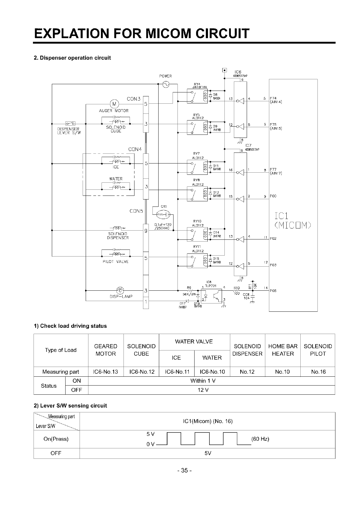
2. Dispenser operation circuit
DISPENSER
LEVER S/W
CON5
AUGER MOTOR
SOLENOID
CUBE
CON4
ICE
I
WA_R I
CONE
SOlYNOID
DISPENSER
PILOT VALVE
OlSP LAMP
POWER
1
CRI
RY4
JWloF74N
RY'a
ALD112
RY7
ALD112
Oll
RY8
ALS112
D12
RYIO
ALDll2
RYII
ALDI12
_@O7 _41€8
IC7
9 _D65003AP
I 8
15 2 9
13 4 11
12
"00
IC1
(NICDN}
"02
"03
"05
1) Check load driving status
Type of Load GEARED
MOTOR
SOLENOID
CUBE
WATER VALVE
ICE WATER
IC6-No.ll IC6-No.10
SOLENOID
DISPENSER
HOMEBAR
HEATER
SOLENOID
PILOT
Measuring part IC6-No.13 IC6-No.12 No.12 No.10 No.16
ON Within 1 V
Status OFF 12 V
2) Lever S/W sensing circuit
_ing ICl(Micom) (No. 16)
part
LeverS/W
On(Press) (60 Hz)
0
OFF 5V
- 35-
EXPLATION FOR MICOM CIRCUIT
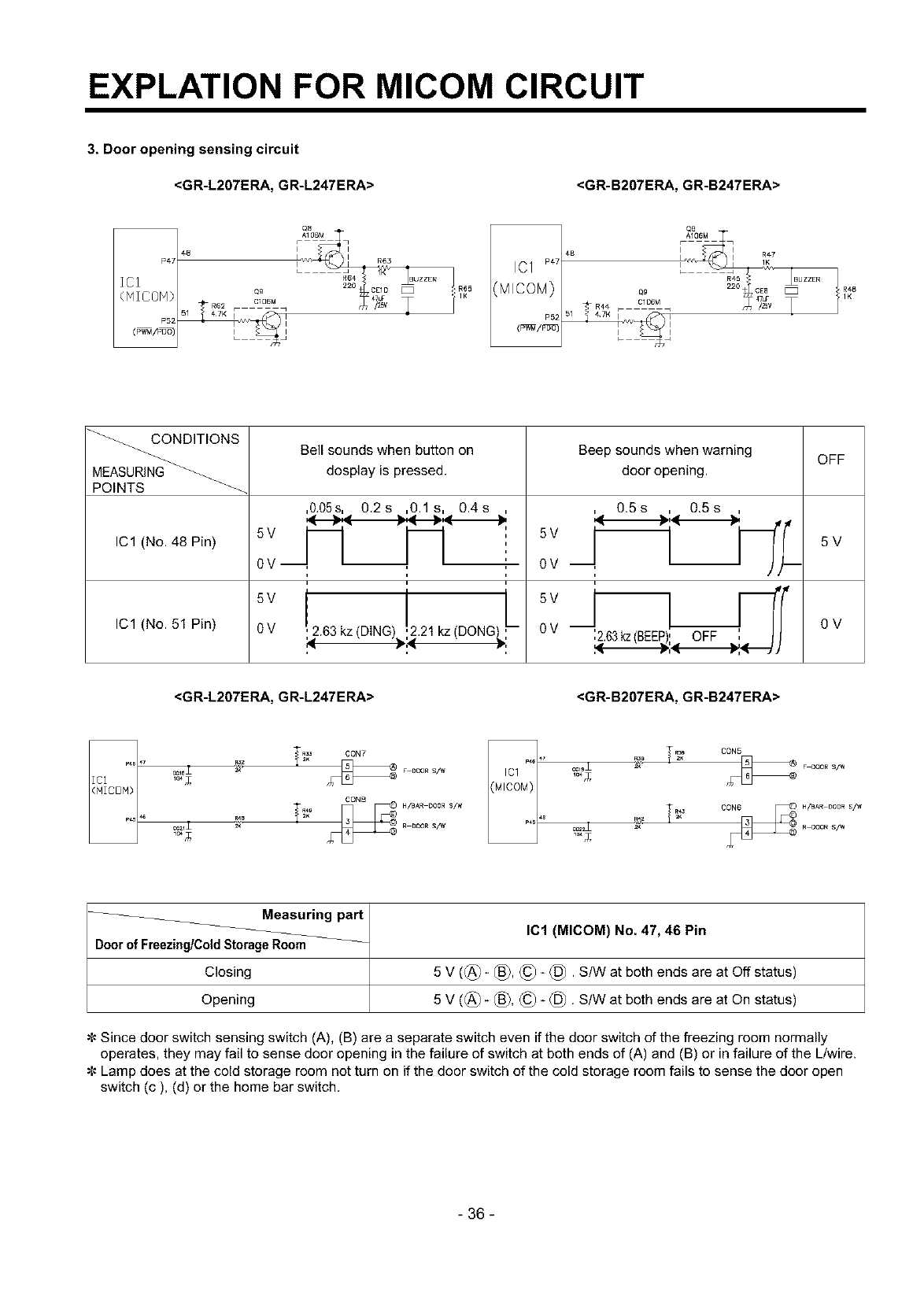
3. Door opening sensing circuit
<GR-L207ERA, GR-L247ERA> <GR-B207ERA, GR-B247ERA>
48
P47
ICI
(NICOM) Q_
R62 C]06M
P52 _v_
P5;
CB
09
_R4.* C] D6M
51 " _TKF 1
_ CONDITIONS
_ Bell sounds when button on Beep sounds when warning OFF
MEASURING_ dosplay is pressed, door opening.
POINTS _-_
,O.05s,, 0.2s ....,0.1s, 0.4s ,j !., 0.5s ,.!., 0.5s
5V -- "' 5V
IC1 (No. 48 Pin)
IC1 (No. 51 Pin)
0V --, , T
0 V ,2.63 kz (DING),..21 kz (DONG
0 V --,
5V
0 V --,2.63kz(BEEP), OFF ',
5V
0V
<GR-L207ERA, GR-L247ERA> <GR-B207ERA, GR-B247ERA>
104_
_C21_
_ _ CON7 F 0OOR S/W
CON5
F OOOR S/W
H/_AR DOOR S/W
ROOOR S/W
Measuring part
Door of Freezing/ColdStorageRoom
Closing
Opening
IC1 (MICOM) No. 47, 46 Pin
5 V ((_)- _3), (_ (_. S/W at both ends are at Off status)
5 V ((_)_ _), (_ (_. S/W at both ends are at On status)
¢- Since door switch sensing switch (A), (B) are a separate switch even if the door switch of the freezing room normally
operates, they may fail to sense door opening in the failure of switch at both ends of (A) and (B) or in failure of the L/wire.
¢- Lamp does at the cold storage room not turn on if the door switch of the cold storage room fails to sense the door open
switch (c), (d) or the home bar switch.
- 36 -
EXPLATION FOR MICOM CIRCUIT
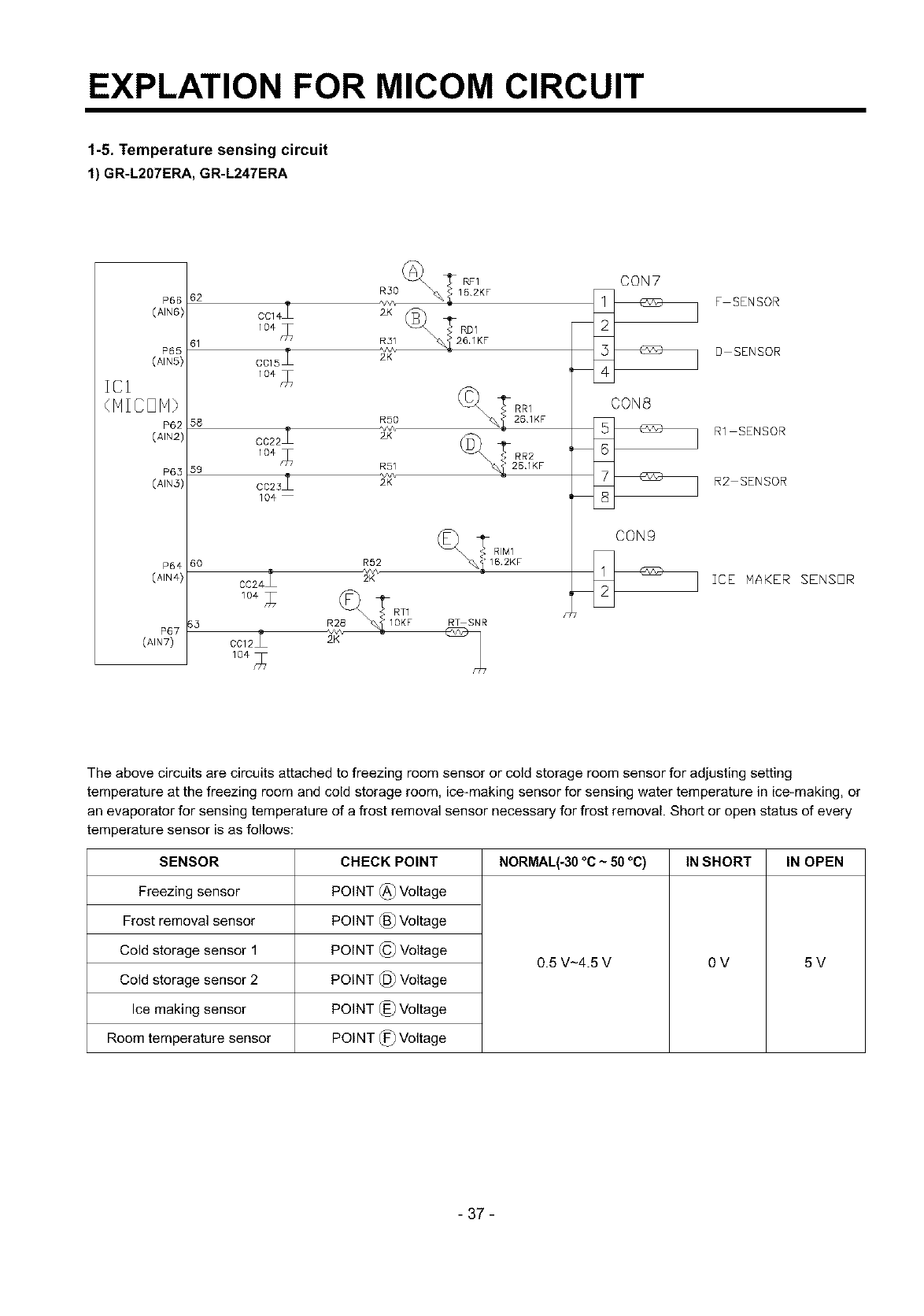
1-5. Temperature sensing circuit
1) GR-L207ERA, GR-L247ERA
zcl
P66
(AIN6)
P65
(AIN5)
P65
(41N3)
P64
(AIN4)
P67
(AIN7)
62 RF1 CON7
R30 _,_ 16.2KF F SENSOR
C 4I r
C015_ 2K D SENSOR
58 RSO
2vv\
C022 2X
5g R51
o023i
104
6o R92
CC24 2K
104 _
CC12_ 2K
RT SNR
CON8
R1 SENSOR
R2 SENSOR
CON9
ICE NAKER SENSOR
The above circuits are circuits attached to freezing room sensor or cold storage room sensor for adjusting setting
temperature at the freezing room and cold storage room, ice-making sensor for sensing water temperature in ice-making, or
an evaporator for sensing temperature of a frost removal sensor necessary for frost removal. Short or open status of every
temperature sensor is as follows:
SENSOR
Freezing sensor
Frost removal sensor
Cold storage sensor 1
Cold storage sensor 2
Ice making sensor
Room temperature sensor
CHECK POINT
POINT (_ Voltage
POINT (_) Voltage
POINT © Voltage
POINT 1_ Voltage
POINT 1_) Voltage
POINT 1_ Voltage
NORMAL(-30 °C ~50 °C) IN SHORT IN OPEN
0.5 V-4.5 V OV 5V
- 37 -
EXPLATION FOR MICOM CIRCUIT
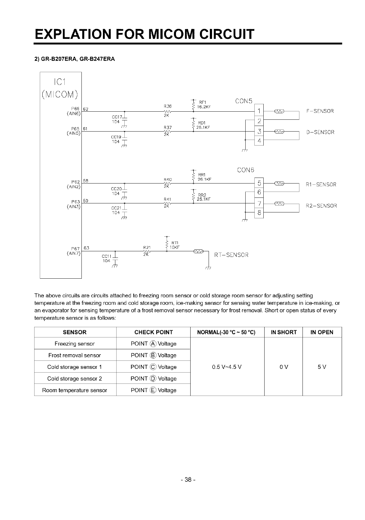
2) GR-B207ERA, GR-B247ERA
ICI
MICOM)
P66
(AIN6)
R36
62
CC17_ 2K
<_f:. RD1
61 R57 _ 26.1KF
*v,v%
CC19_ 2K
58 R4O
CC20 2K
59 R41
2_v\
CC21 2K
10€n_ 7
CON5
,_RR1 CON 6
261KF
_261KF
T RT1
63 R21 _ IOKF
CCl1_ _/K'_ - _ RT SENSOR
F SENSOR
D SENSOR
R1 SENSOR
R2 SENSOR
The above circuits are circuits attached to freezing room sensor or cold storage room sensor for adjusting setting
temperature at the freezing room and cold storage room, ice-making sensor for sensing water temperature in ice-making, or
an evaporator for sensing temperature of a frost removal sensor necessary for frost removal. Short or open status of every
temperature sensor is as follows:
SENSOR
Freezing sensor
Frost removal sensor
Cold storage sensor 1
Cold storage sensor 2
Room temperature sensor
CHECK POINT
POINT (_) Voltage
POINT (_) Voltage
POINT (_ Voltage
POINT @ Voltage
POINT (_) Voltage
NORMAL(-30 °C ~50 °C) IN SHORT IN OPEN
0.5 V_4.5 V OV 5V
- 38 -
EXPLATION FOR MICOM CIRCUIT
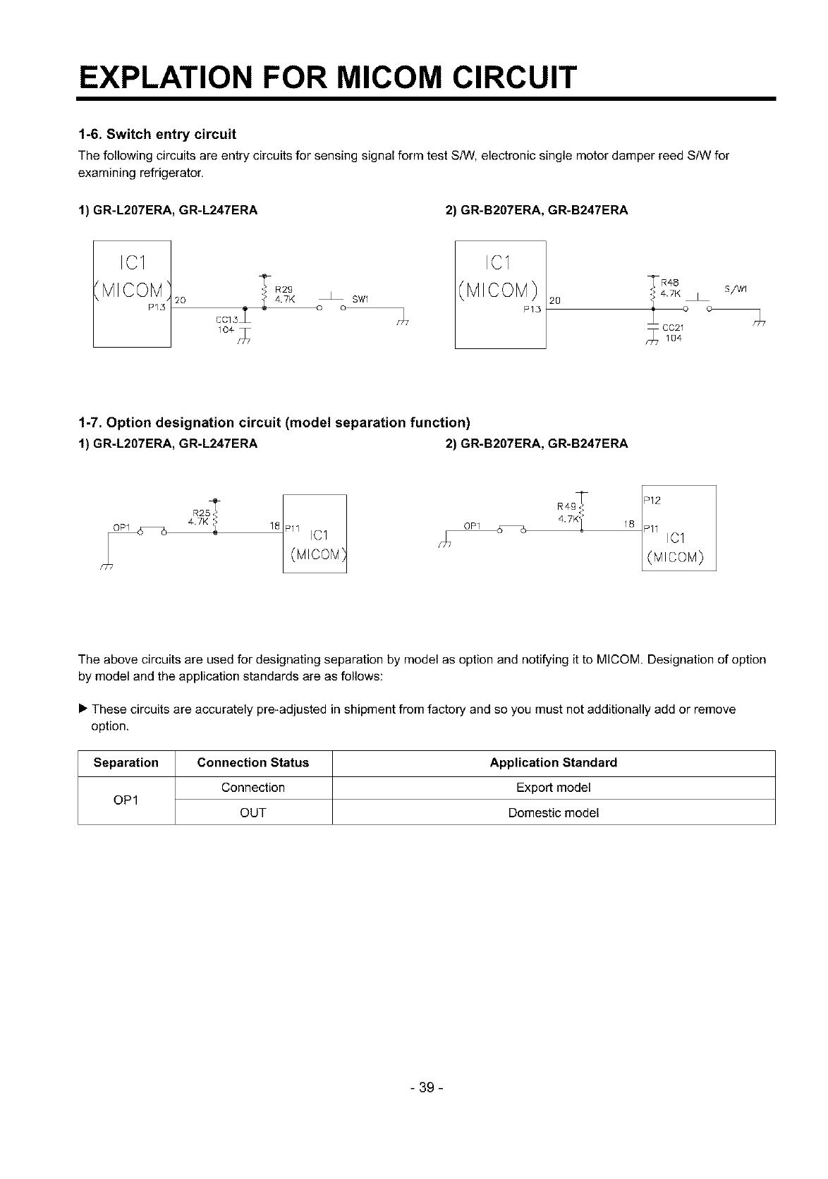
1-6. Switch entry circuit
The following circuits are entry circuits for sensing signal form test S/VV,electronic single motor damper reed StW for
examining refrigerator.
1) GR-L207ERA, GR-L247ERA 2) GR-B207ERA, GR-B247ERA
IC1
MICOM
P15
_R2g
20 _ 47K o_ o SW1
cc13L _7
IC1
(MICOM}
P15 2O
1-7. Option designation circuit (model separation function)
1) GR-L207ERA, GR-L247ERA 2) GR-B207ERA, GR-B247ERA
R2S'_ Pll 161
47K 1 18
hi7 (MIOOM}
112R4 18 11 IC1
L(MIcoM)
The above circuits are used for designating separation by model as option and notifying it to MICOM. Designation of option
by model and the application standards are as follows:
• These circuits are accurately pre-adjusted in shipment from factory and so you must not additionally add or remove
option.
Separation Connection Status Application Standard
Connection Export model
OP1 OUT Domestic model
- 39 -
EXPLATION FOR MICOM CIRCUIT
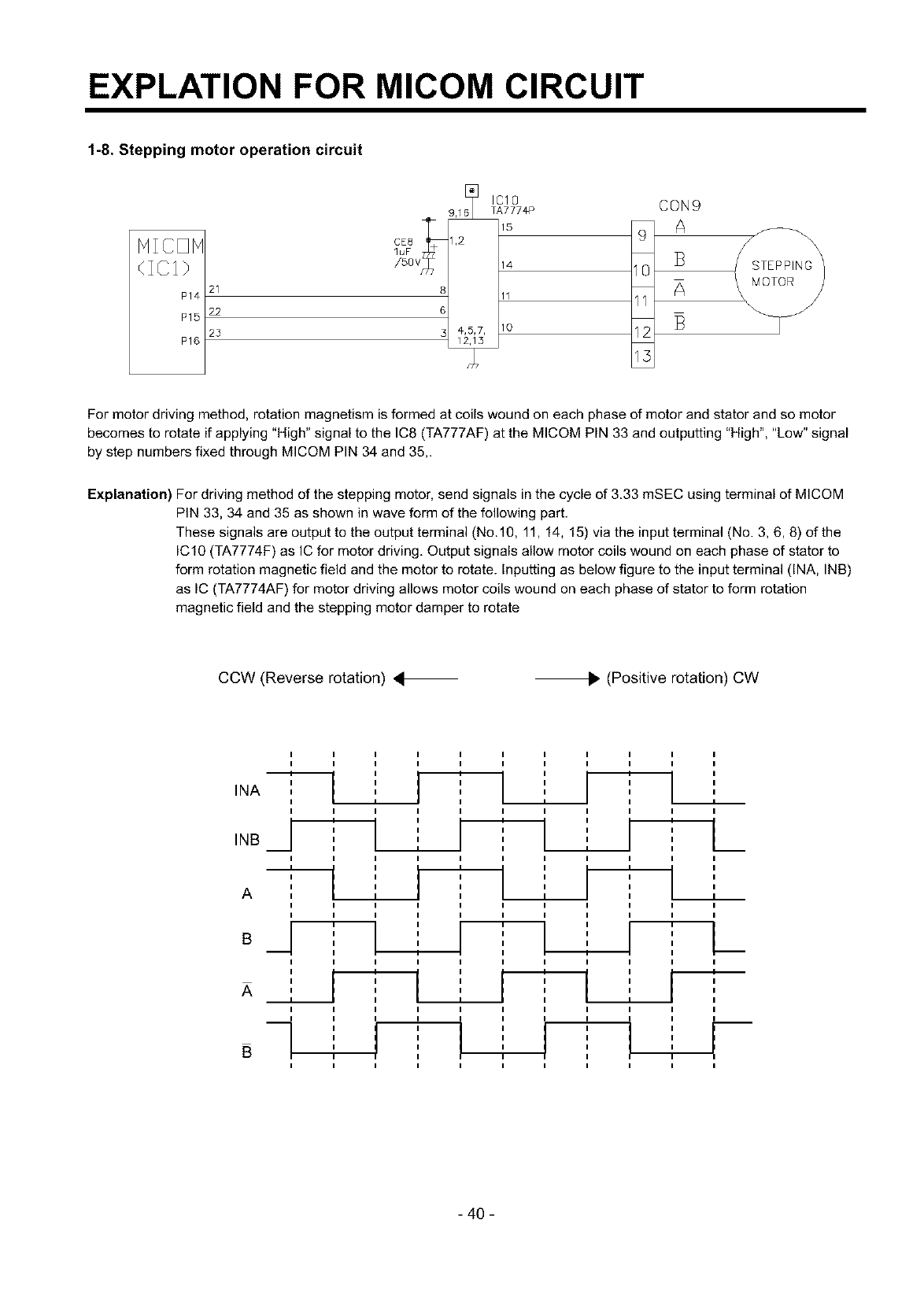
1-8. Stepping motor operation circuit
HIOOH
P14
P15
P16
21
22
25
9,16
CE8 1,2
luF 68_
/5ov
3 4,_
IC10 CON9
TA777#P
14 10
11 11
12 13
13
\
STEPPING
MOTOR
For motor driving method, rotation magnetism is formed at coils wound on each phase of motor and stator and so motor
becomes to rotate if applying "High" signal to the IC8 (TA777AF) at the MICOM PIN 33 and outputting "High", "Low" signal
by step numbers fixed through MICOM PIN 34 and 35,.
Explanation) For driving method of the stepping motor, send signals in the cycle of 3.33 mSEC using terminal of MICOM
PIN 33, 34 and 35 as shown in wave form of the following part.
These signals are output to the output terminal (No.10, 11, 14, 15) via the input terminal (No. 3, 6, 8) of the
IC10 (TA7774F) as IC for motor driving. Output signals allow motor coils wound on each phase of stator to
form rotation magnetic field and the motor to rotate. Inputting as below figure to the input terminal (INA, INB)
as IC (TA7774AF) for motor driving allows motor coils wound on each phase of stator to form rotation
magnetic field and the stepping motor damper to rotate
CCW (Reverse rotation) 4_. (Positive rotation) CW
IIIIIIIIIII
IIIIIIIIIII
INA ,
I
IIIIIIIIIII
/ ' ' I --L'
INB I
I I I I
,-_ ,,,, } ,
I
A I I
I I I I
I I I I
o_1
I I I
I I
I I
.._ I I
I I I
i i
I I I
IIII
I ,
IIII
' ' i
"T" I
I I
I I
I I
I I I
I I I I
i i
I I
I I
I I
-r r
I I I I
I
L
I
I
i-
I
- 40 -
EXPLATION FOR MICOM CIRCUIT
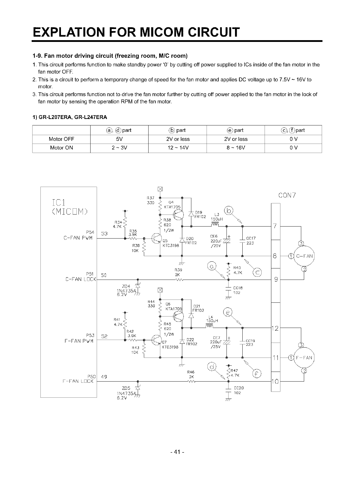
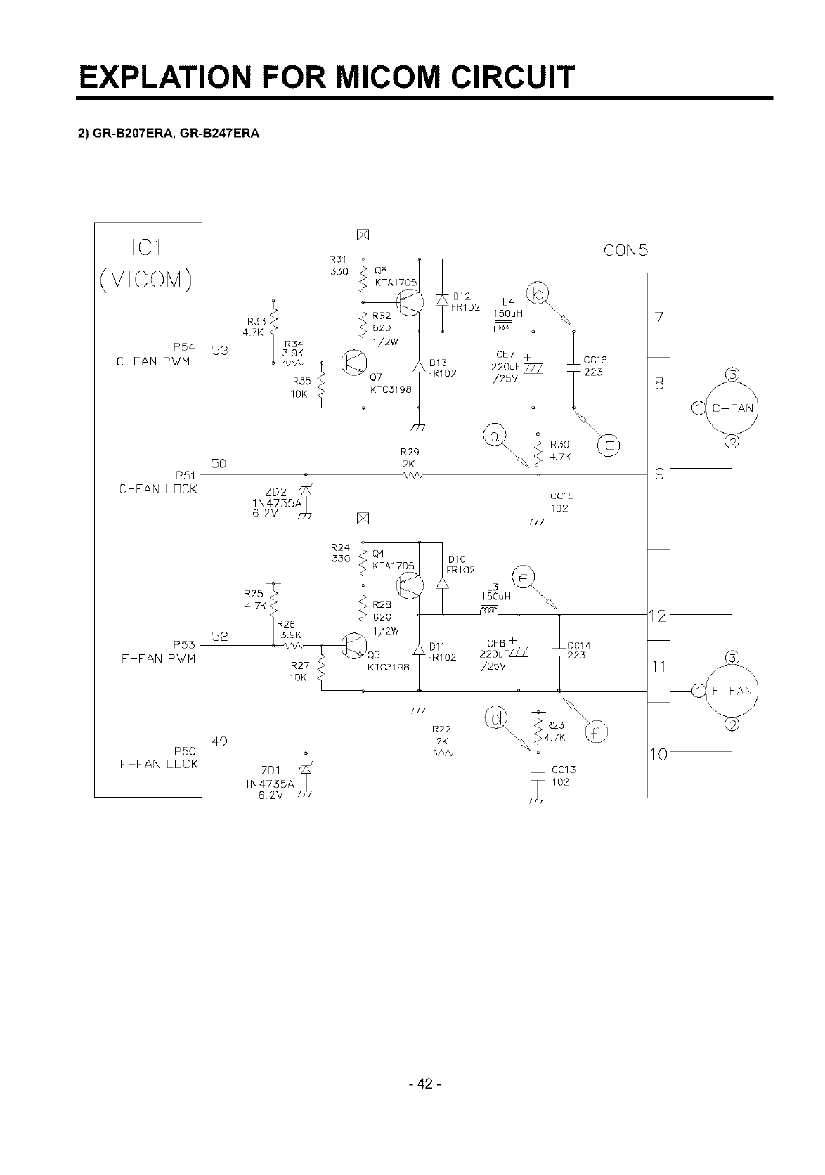
1-9. Fan motor driving circuit (freezing room, M/C room)
1. This circuit performs function to make standby power '0' by cutting off power supplied to ICs inside of the fan motor in the
fan motor OFF.
2. This is a circuit to perform a temporary change of speed for the fan motor and applies DC voltage up to 7.5V - 16V to
motor.
3. This circuit performs function not to drive the fan motor further by cutting off power applied to the fan motor in the lock of
fan motor by sensing the operation RPM of the fan motor.
1) GR-L207ERA, GR-L247ERA
Motor OFF 5V
Motor ON 2 - 3V
(_) part (_) part (_), c_)part
2V or less 2V or less 0 V
12 - 14V 8- 16V OV
P54
C FAN PWM
P51
C FAN LOCK
P53
F FAN P_!M
PSO
F FAN LOCK
53
5O
52
49
4,7K R35
R36 <<>
1OK _>
R41
R¢4
350 021
FR1D2
_42
R43
1OK
R#6
2K
/,,/v,
L_
15DuH
220uF CC19
/25V _223
\_ _#7K
CC20
6.2V
CON7
7
9
11
I0
-41 -
EXPLATION FOR MICOM CIRCUIT
2) GR-B207ERA, GR-B247ERA
IC1
(MICOM)
P54
C FAN PV/M
P51
C FAN LOCK
P53
F FAN PWM
PSO
F FAN LOCK
4.7K
53
5O
52
49
R55
1OK
zD2
1N¢735A
6.2V _r77
R31
330
R24
330
R29
2JK
R:2B
62O
1/2w
85 /Dll
& FRI02
K7C31 g8
R22
2K
CON5
L4
150uH: 7
I-
2_E7F * _CC16
/25v T225 8
\4.7K
9
CC15
77 02
22CDEuSF+ L2C2C14
/2sv T 11
\
%] cc_3 10
/_7 102
(
(
- 42 -
EXPLATION FOR MICOM CIRCUIT
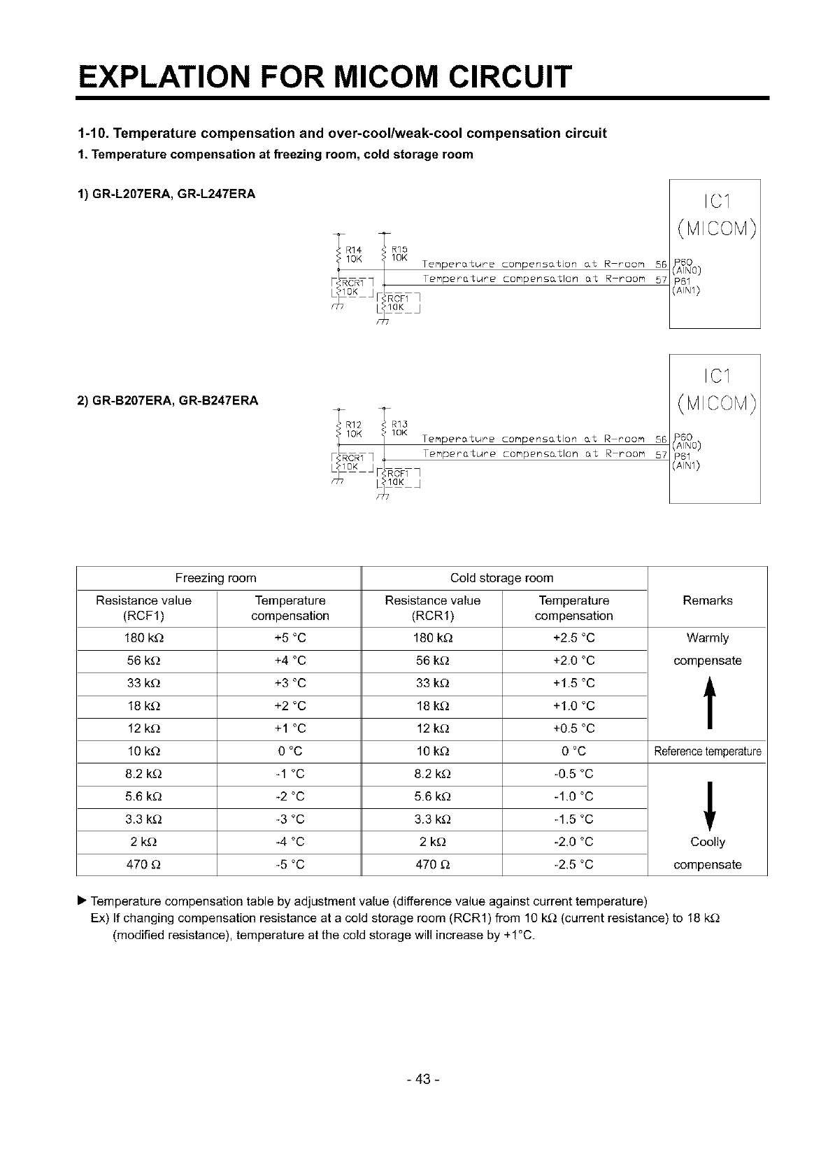
1-10. Temperature compensation and over-cool/weak-cool compensation circuit
1. Temperature compensation at freezing room, cold storage room
1) GR-L207ERA, GR-L247ERA
IRR14 _R15
OK ]'IOK Temperature compens&tion &t R moore 55
CRTq _ Temperature compens_tlon at R room 57
_laK J
ICI
2) GR-B207ERA, GR-B247ERA
_-• R12 _[ R13
'Ft_OK i IOK Temperature compensation at Rroom 56
CRT] Temperature compens&tlon at R room 57
ICI
Freezing room Cold storage room
Resistance value Temperature Resistance value Temperature Remarks
(RCF1) compensation (RCR1) compensation
180 k_ +5 °C 180 k_ +2.5 °C Warmly
56 k_) +4 °C 56 k_ +2.0 °C compensate
33 k_) +3 °C 33 k_ +1.5 °C
18 k£_ +2 °C 18 k£_ +1.0 °C
12 k£_ +1 °C 12 k£_ +0.5 °C
10 k_ 0 °C 10 k_ 0 °C Referencetemperature
8.2 k_ -1 °C 8.2 k_ -0.5 °C
5.6 kD -2 °C 5.6 k_ -1.0 °C
3.3 k£_ -3 °C 3.3 k_ -1.5 °C '
2 k_) -4 °C 2 k_) -2.0 °C Coolly
470 _ -5 °C 470 £_ -2.5 °C compensate
• Temperature compensation table by adjustment value (difference value against current temperature)
Ex) If changing compensation resistance at a cold storage room (RCR1) from 10 kD (current resistance) to 18 k_
(modified resistance), temperature at the cold storage will increase by +1°C.
- 43 -
EXPLATION FOR MICOM CIRCUIT
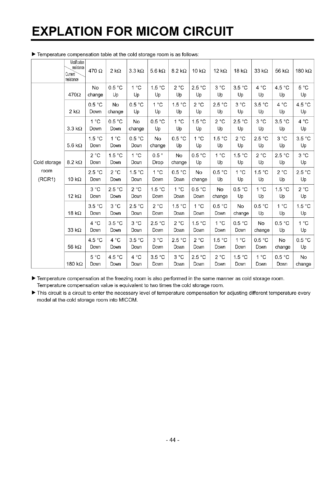
• Temperature compensation table at the cold storage room is as follows:
Mod_icaton
470£_ 2kD 3.3kD 5.6kD 8.2k£_ 10k£_ 12kD 18kD 33kD 56kD 180kD
Cold storage
room
(RCR1)
resistance
No 0.5 °C 1 °C 1.5 °C 2 °C 2.5 °C 3 °C 3.5 °C 4 °C 4.5 °C 5 °C
470D change Up Up Up Up Up Up Up Up Up Up
0.5 °C No 0.5 °C 1 °C 1.5 °C 2 °C 2.5 °C 3 °C 3.5 °C 4 °C 4.5 °C
2 kD Down change Up Up Up Up Up Up Up Up Up
1 °C 0.5 °C No 0.5 °C 1 °C 1.5 °C 2 °C 2.5 °C 3 °C 3.5 °C 4 °C
3.3 k_) Down Down change Up Up Up Up Up Up Up Up
1.5 °C 1 °C 0.5 °C No 0.5 °C 1 °C 1.5 °C 2 °C 2.5 °C 3 °C 3.5 °C
5.6 k_) Down Down Down change Up Up Up Up Up Up Up
2 °C 1.5 °C 1 °C 0.5 ° No 0.5 °C 1 °C 1.5 °C 2 °C 2.5 °C 3 °C
8.2 k_) Down Down Down Drop change Up Up Up Up Up Up
2.5 °C 2 °C 1.5 °C 1 °C 0.5 °C No 0.5 °C 1 °C 1.5 °C 2 °C 2.5 °C
10 kD Down Down Down Down Down change Up Up Up Up Up
3 °C 2.5 °C 2 °C 1.5 °C 1 °C 0.5 °C No 0.5 °C 1 °C 1.5 °C 2 °C
12 kD Down Down Down Down Down Down change Up Up Up Up
3.5 °C 3 °C 2.5 °C 2 °C 1.5 °C 1 °C 0.5 °C No 0.5 °C 1 °C 1.5 °C
18 kD Down Down Down Down Down Down Down change Up Up Up
4 °C 3.5 °C 3 °C 2.5 °C 2 °C 1.5 °C 1 °C 0.5 °C No 0.5 °C 1 °C
33 kD Down Down Down Down Down Down Down Down change Up Up
4.5 °C 4 °C 3.5 °C 3 °C 2.5 °C 2 °C 1.5 °C 1 °C 0.5 °C No 0.5 °C
56 kD Down Down Down Down Down Down Down Down Down change Up
5 °C 4.5 °C 4 °C 3.5 °C 3 °C 2.5 °C 2 °C 1.5 °C 1 °C 0.5 °C No
180 kD Down Down Down Down Down Down Down Down Down Down change
• Temperature compensation at the freezing room is also performed in the same manner as cold storage room.
Temperature compensation value is equivalent to two times the cold storage room,
• This circuit is a circuit to enter the necessary level of temperature compensation for adjusting different temperature every
model at the cold storage room into MICOM.
- 44 -
EXPLATION FOR MICOM CIRCUIT
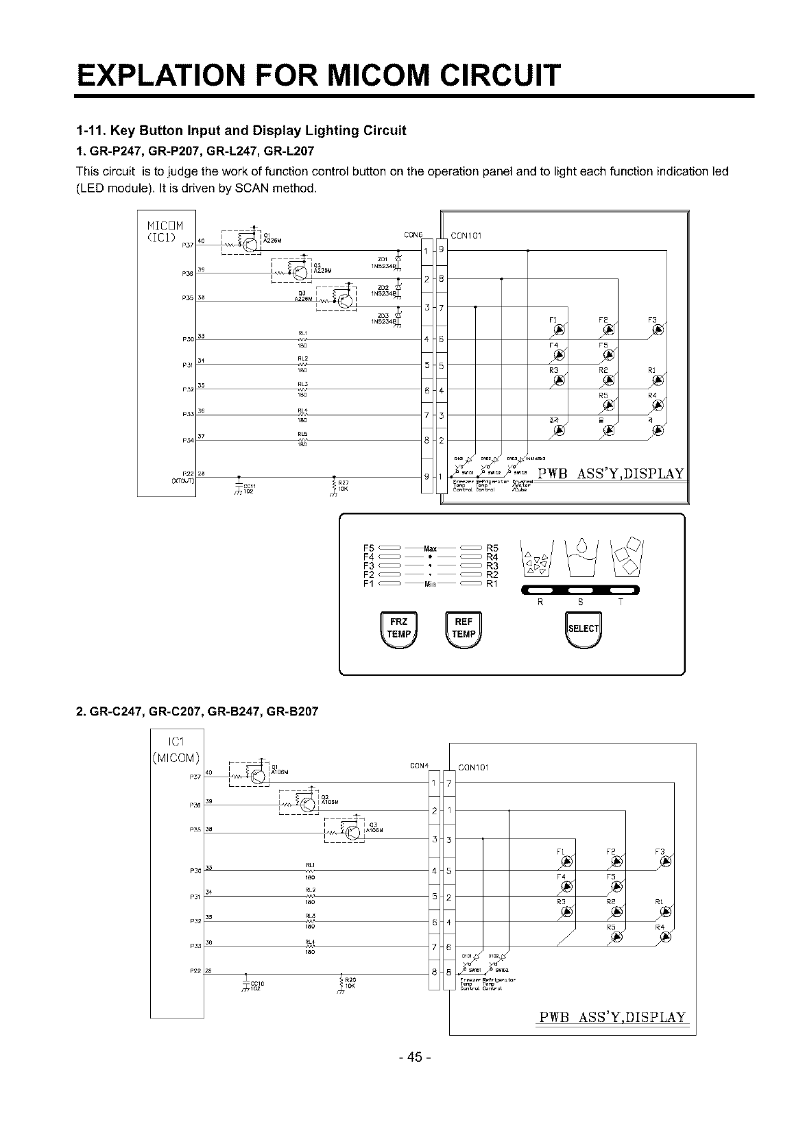
1-11. Key Button Input and Display Lighting Circuit
1. GR-P247, GR-P207, GR-L247, GR-L207
This circuit is to judge the work of function control button on the operation panel and to light each function indication led
(LED module). It is driven by SCAN method.
MICOM
(IC1) r_s7
P36
P35
Pao
P31
ea_
P33
ca4
F_ o_
i _ i A228M
L
A226M
CON6
RL1
IB0
RL2
IB0
R+
IBO
28
RZ7
_ICD(11 _zIOK
CON101
F2 F3
F4 F5
R3 R2 RI
R5 R4
'PWB ASS'Y,DISPLAY
F5 _ Max _ R5
F4 _ • _ R4
F3 _ _ R3
F2 _ _ R2
F1 _ Min _ R1
R S T
2. GR-C247, GR-C207, GR-B247, GR-B207
IC1
{MICOM)
P37
P36
P35
P30
Pal
P32
P33
P22 2a ±CClO
_1o2
RLI
18O
eL2
180
180
CONe CON101
FI F2 F3
F4 F5
R3 R2
sm_
T_ T_r_
o. _o o_o
PWB ASS'Y,DISPLAY
-45 -
EXPLATION FOR MICOM CIRCUIT
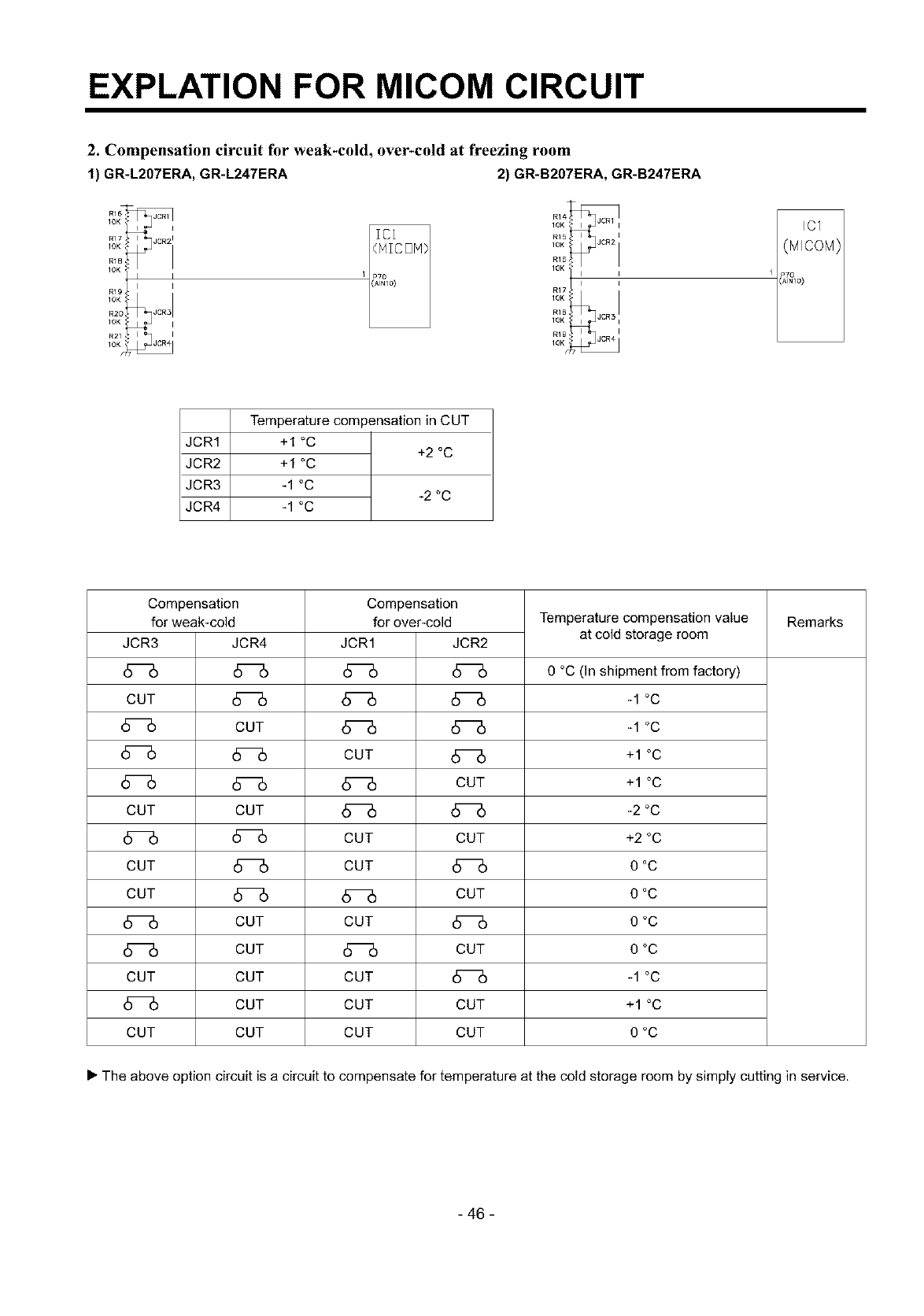
2. Compensation circuit for weak-cold, over-cold at f?eezing room
1) GR-L207ERA, GR-L247ERA 2) GR-B207ERA, GR-B247ERA
R15
1OK •
RIB]
1OK
R17
10K <
IC1
JCR1
JCR2
JCR3
JCR4
Temperature compensation in CUT
+1 °C +2 °C
+1 °C
-1 °C -2 °C
-1 °C
Compensation
for weak-cold
JCR3
CUT
CUT
CUT
CUT
CUT
CUT
JCR4
CUT
CUT
CUT
CUT
CUT
CUT
CUT
Compensation
for over-cold
JCR1 JCR2
CUT
CUT
CUT CUT
CUT
CUT
CUT (_
(_ CUT
CUT (_
CUT CUT
CUT CUT
Temperature compensation value
at cold storage room
0 °C (In shipment from factory)
-1 °C
-1 °C
+1 °C
+1 °C
-2 °C
+2 °C
0°C
0°C
0°C
0°C
-1 °C
+1 °C
0°C
Remarks
• The above option circuit is a circuit to compensate for temperature at the cold storage room by simply cutting in service.
- 46 -
EXPLATION FOR MICOM CIRCUIT
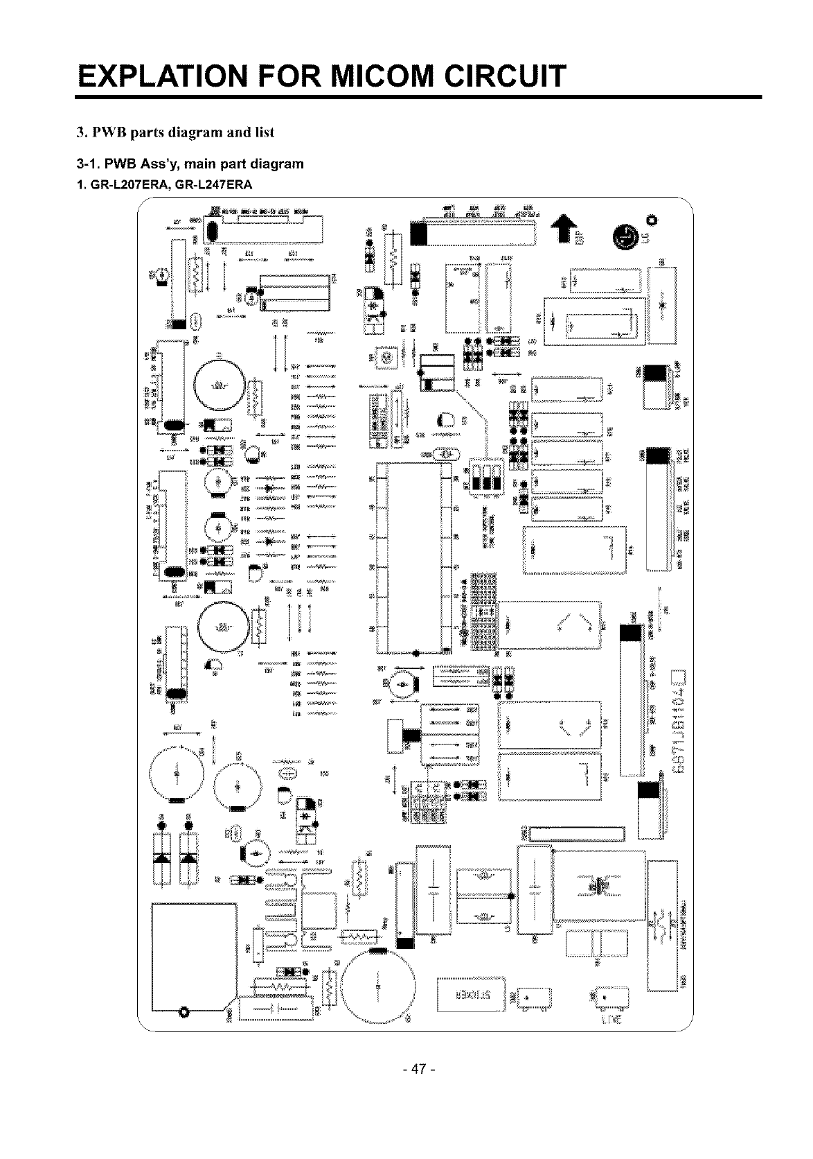
3. PWB parts diagram and list
3-1. PWB Ass'y, main part diagram
1. GR-L207ERA, GR-L247ERA
f
il.r_ J
- 47 -
EXPLATION FOR MICOM CIRCUIT
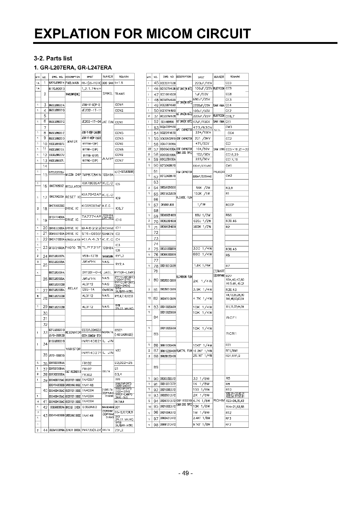
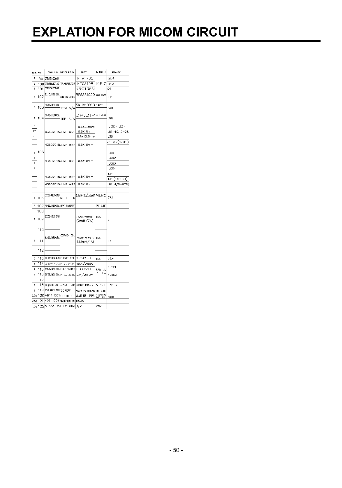
3-2. Parts list
1. GR-L207ERA, GR-L247ERA
NO DWG NO. 3ESCRIP]qO_ SpEU' MAKER REUARK
1 iB70JBSfll_ PWB,MAIN FR I(DS 11Q7A', 300 £AN L=16
i170JB201_ 1,2:1 7_mE
2]RA_9_S_{£L) SAM[L TRANS
3 i630JBB001/ J[202I[62(_P21 CON4
4 _630JB8001[ JE2D2 1_1 CON2
5
T _630JB8001[ dE202 1T 04 JAE EUN CON1
_3uJa_Om; _t_IT_[9_4__ CON5
9 _630JB8001[ J_211 ,'K_-_,_,BI CON3
WAFER
10 BBSOJBBO07C 917786 I(BP) CON6
11 5530JBBOIG_ 9177_1 103P) CONB
12 8030,8a007, 91/768-1(10P} CONg
13 BB30JBBOa7L 917790 102P) AMP C 0N7
14
1 5 )IZZJB2009'_ MICOM CHI TMp87cB41 k TOSHIBA CI(=glZZJBTOOBB}
KIA7BOOSAF K.E.C IC5
15 DIKE7BO5OOZREGULATOI
KIA7042AP <.E.C
17 OIKETO4200ARESET IC9
}IKEBSOD30( KIDBSOO3AF KEC
10 DRIVE IC IC6,7
_OSHIB
_ iCl 0
)1T0777400t TA7774AF
19 DRIVE IC
20 )1RH6222001 DRIVE IC BA6222 ROHM ICll
21 )1SK65510{]I DRIVE IC STR G655 SANKEN IC2
22 }1KE¢3100{]1 /REGULATOFKlAn5 _ <.E.C IC4
IC3
23 )1T0721000t PHOTO q_ TLP721 F TOSHIBA
IC8
24 _920,820071 VSB 1210 TAKAWI_AfiARYI,3
i920,1t20051 JWlaFHN NAIS
25 RY2¢
_920_200€i DH12DI 0 ( JAEIL _Y11(R LAMP]
26 _920,B2005/ JWlaFHN NAIS
_Yll LXHU_I
_920JB2003[ ALD112 NAIS 220~240v
27 _g20_20091 RELAY GSS 1A OMRON RYI¢
(H/BAR Hm)
28 i920JB20031 ALD112 NAIS RY5,6,710,12,13
29_920JB2003E ALDllZ NAIS RY8
rPiim V_IYF)
30
51
32
i212JBBOOIE CSTS4.0OMGO3 OSCl
_ RESONATOI _URATA
J570 O0012E CST¢OOMG_TF_ (=6212_090@28)
_I02JBBOOIE INR1 _062" •JIN
3#
VARISTOF VAI
INRI#D27" • dIN
_5 ]572 00001[
3_) ]DR10200flAI FRI02 02,D22_25
_7 )DRIOTOOflAI FRI07 01
F_STRECO_L_ DELTA
_B )DR302000BI FR3D2 D3,4
_9 )DD469709A( REC_R5_gl@ IN4007 020
D1B EXPORT)
]DD41480gB[ SIdfCHINGglOg IN4148 (22_2¢0v)
40 )DD40040gA( REC_R5_DI@ 1N4004 [1)DELTA
:_)p"UNC
)DD40040gA( REC_R5_DI@ IN4004 CHANC
41 )D0400409A( REC_R5_DI@ IN4004 _67&_
42 ODB_60_OOA_BRIDC_DIOO D3SBA60 ;HINDEN_IBD1
(1)ROHM
4_ ]DD414_09B[ SId[CHINGDIOD1N4140 (_) m'uN_
CHANt
(H/BAR HTR)
4,$ 30ZWROOO1glZENERDIOD 1N4735(6 2V DELTA ZD1,2
)CE2271FB31
)_EIO71H&_
3CE1061K63_
)_E687AH69[
)CE22B7H69[
]CE107AH61[
)_E227AHB3f
Q_E476B_6_O
)CQ¢732Y43[
)C@241N63[
)CK2210_51[
)CK¢71DK961
)CKIO@K@BI
)CKIO2BK_BI
)CK2A3DKgBI
)0F35€3067[
)CF22_0067[
)RS5602K60(
)RS1503J601
ORSOIOIJBO_
]RDO652H60[
)RD6200H60!
)RD5603H60!
)RD3500860!
)RD6BOOB60!
)RDIBOlGBOi
)RD2001G60!
3RB3901G60!
)_04701666!
]RDIOO2G60!
)RD1002G60[
]RD1002G60!
)RN1002G_43!
)_N16226401
)_N2612G_
)RDO532E@7;
]RD1001E67;
]RD1OOOE67;
]RD2001E67;
)RD4701E67;
)RD1gO2E67_
)RD190_67;
]RN24aIE47;
)RNgIOIE¢7;
3ESCRIP_O_ SPEC,
220uF/16V
E¢_'("K _ 100uF/25V
1uF/50V
E¢&!p_,(_i_ _ 680uF/25V
2200uF/25V
lOOuF/50V
E¢I_G I_ 220uF/25V
d_I_ €7uF/450V
MyL'CAp_TO 473/5_0V
22€/10QV
CSR'CAP_TO 221 /2KV
471/50V
CSR'gAP_aTO 104/50V
(_B 28127rPE 102/50V
223/50V
33DnF/275VAC
FILMCAPAClTO
220nF/275VAC
56K /2W
150K /lW
R,OXIDEFlU
1/1W
68J 1/2W
620J 1/2W
560K 1/2W
350 1/#W
680 1/4W
18K 1/4W
R,CARBONRU
2K 1/4W
3.9K 1/4W
#7K 1/#W
1OK 1/4W
1OK 1/4W
1OK 1/#W
1QKF 1/4W
R,METALRLI 16 2KF 1/4W
261KF 1/4W
33 1/8W
1K 1/8W
100 1/8W
2K 1/BW
CHIPRESISTO4.7K 1/8W
(9_D2011hE 1OK 1/8W
1M 1/8W
2.4KF 1/8W
91KF 1/BW
MAKER REMARK
2E5
{UBYCON CE9
CE8
3E3
_AM HWA 3E4
3E2
_UBYCON 3E6,7
_AM HWA 3E1
3M3
SEIL
CC4
CC2
CC1
SA_ HWA CC5_16,21_31
CCIB,2D
CC17,19
CM1
PILKOR
CM2
R3,9
R1
ROCP
R65
R39€6
R2
R38€5
R6
R7
(1)SF_ART
(2)C_y_ R27
R54,40,€7,50
R58,62
R36#3
R¢,13,25,28,30
R¢1,48,60,63,6€
Rl1,15,37,4€,5€
RCF1
RCR1
RT1
RF1,RIMI
RDI,RRI,2
R5
R8
RIO
R29,_1_33,_9,51
R5256 5759 61
ROHM R22_24,55,€2
R14_21,53,55
R12
RF3
RF2
- 49 -
EXPLATION FOR MICOM CIRCUIT
io BWG NO DESCRIPq]ON SpEC' MAKER REMARK
99 )_KE900041 KTA1705 Q2,4
IOC )TR31g_ogA: TRANSISTOR KTC_198 KEC q_,5
01 Iml0G009AF (RC1 O6rv Q1
i210JBBO011 _FS3510AC s_ HW_
02 &_(CIE),B[_S FBI
_600JBBO011 ;KHV1091E TACT
0_ TEST S/W SW1
04
05
_600JB80031 3 P, D I F OTAX
mP S/W SW2
0 6X7 5m_ J29_J34
4360701_ JUMP WIRE 0 6X10mm J01_10,12_2l
0 6X12 5m_ J35
JF1,JF2(FUSE1
4360701_ JUMP WIRE 06XlOmm
JCR1
JCR2
4360701_ JUMP WIRE 06XlOmm JCR3
JCR4
OP1
4360701_ JUMP WIRE 06XlOmm OP1 (EXPORT)
4360701_ JUMP WIRE 06XlOmm JHI(H/B HTR
i200JBSOB1E luF+120/350VA[PILKC
06 RC FILTER CR1
07 _g20JB3007J HEATSINK(STR) TAESUN_
08
_200JB3004E ;Vg70020 TNC
Og [2mH/7A) L1
110
CGMMDNCOIL
_200JBBOOSJ DV910320 TNC
I 11 (32mH/1 A) L2
112
113 3LRISOQK4JCCHOKE COIL I 50u H TNC L314
I 14 3J02447C F U S E 15A/250V
115 ig01JBSO011 FUSEHOLDER_C61 F SAM JL FUSE1
I 16 IFZZJB30011 F U S E 2AJ250V lit t l e FUSE2
117
118 DDOIO30F 250 TAB ;p881191 2 KET TAB1,2
I19 ISBFOSO241ESCREW ss'¥ TO H/SlN_ TAESUN_
12C €g11100 SOLDER _MIT KR lgRM_ HlSUNC
DAE JIN SOLD
121 _9111004 S_OELE_B8 t63A
122 5933310_ FLUX AUTO IS71 KOKI
- 50 -
EXPLATION FOR MICOM CIRCUIT
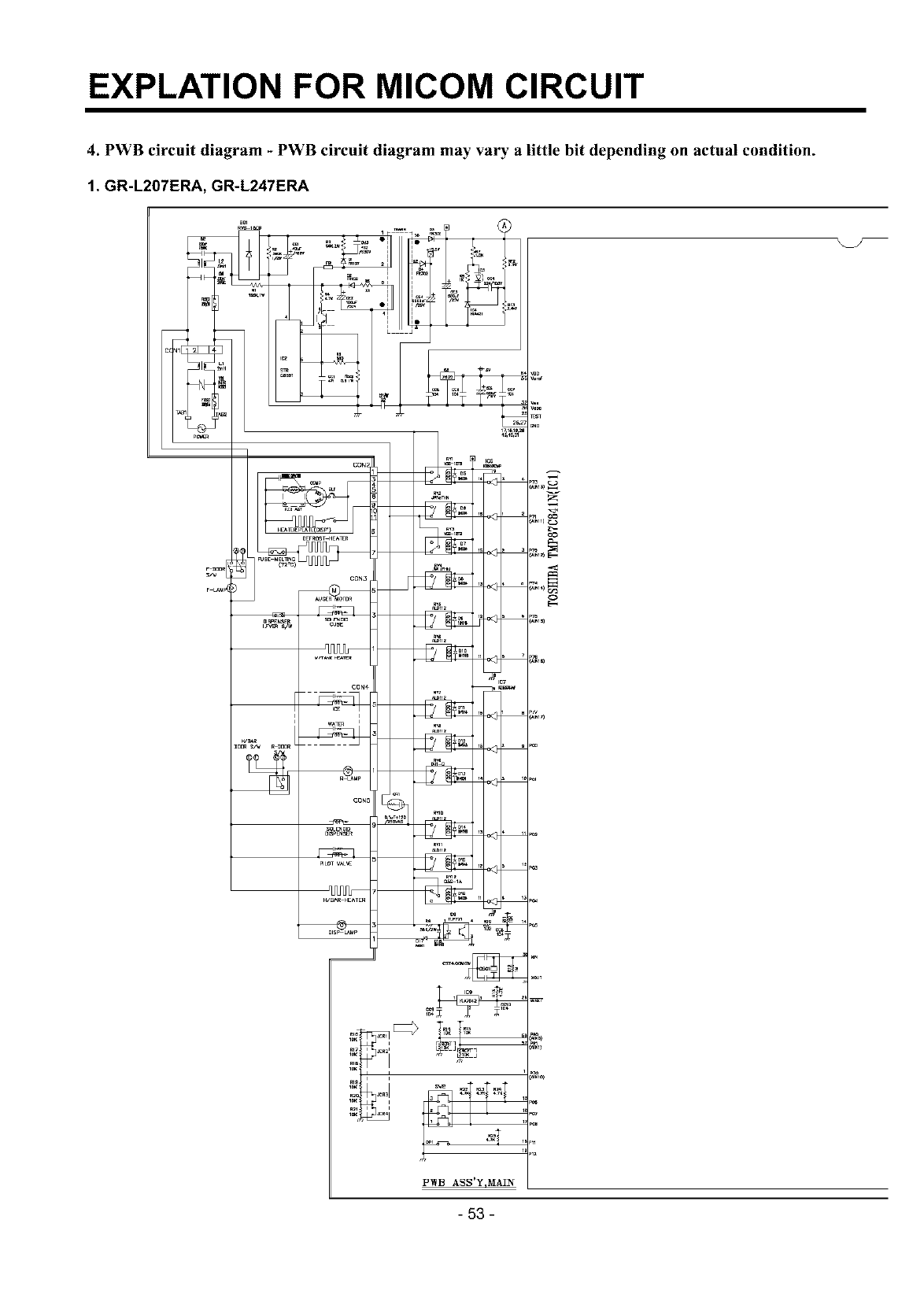
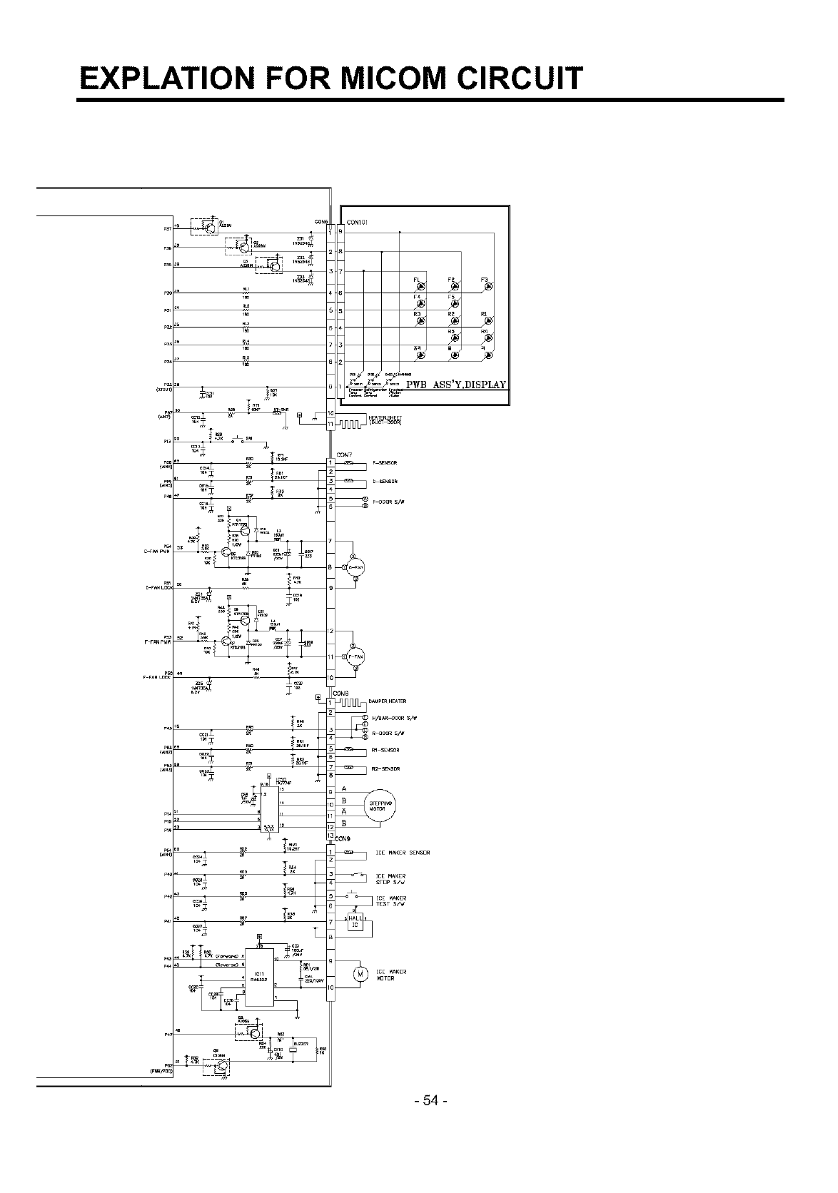
4. PWB circuit diagram - PWB circuit diagram may vary a little bit depending on actual condition.
1. GR-L207ERA, GR-L247ERA
cIN1E
PWB ASS'Y,MAIN
o
,/i
P_
-53 -
EXPLATION FOR MICOM CIRCUIT
-54 -
ICEMAKERANDDISPENSEROPERATIONPRINCIPLEANDREPAIRMETHOD
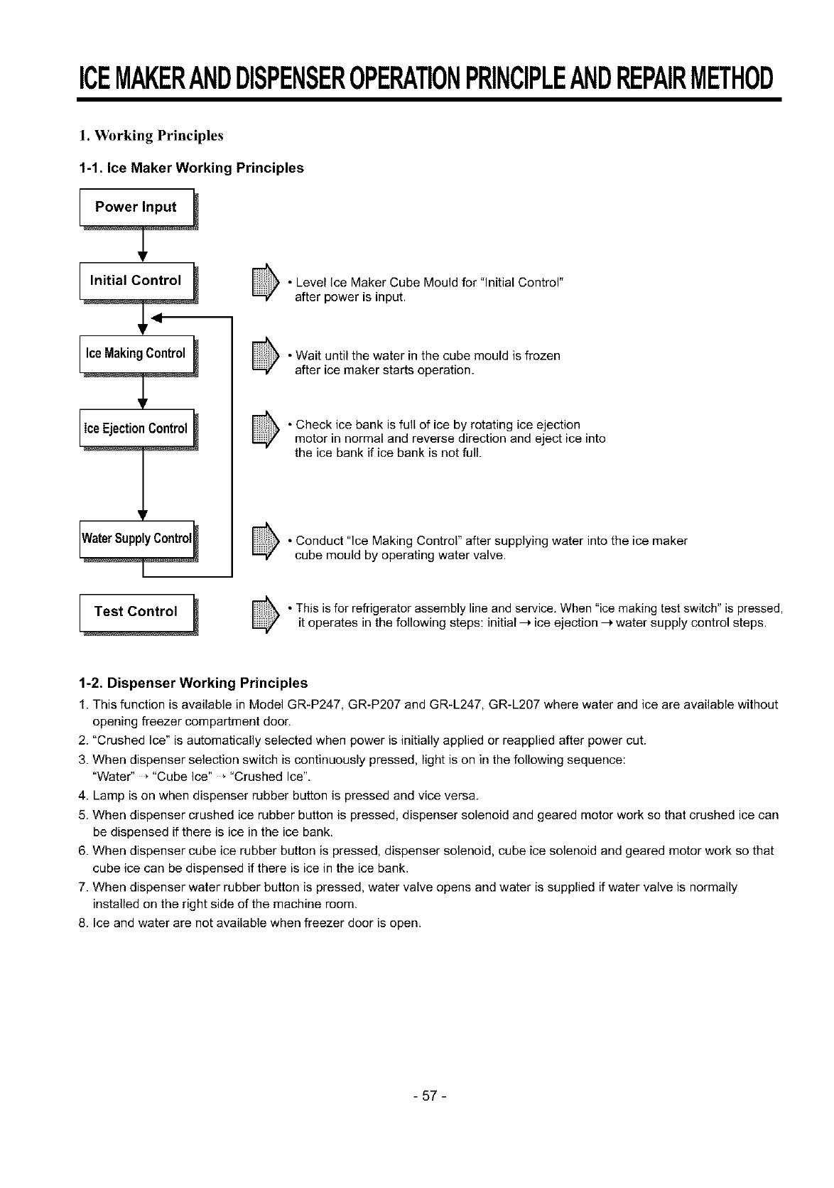
1. Working Principles
1-1. Ice Maker Working Principles
• Level Ice Maker Cube Mould for "Initial Control"
after power is input.
• Wait until the water in the cube mould is frozen
after ice maker starts operation.
• Check ice bank is full of ice by rotating ice ejection
motor in normal and reverse direction and eject ice into
the ice bank if ice bank is not full.
• Conduct "Ice Making Control" after supplying water into the ice maker
cube mould by operating water valve.
• This is for refrigerator assembly line and service. When "ice making test switch" is pressed,
it operates in the following steps: initial --_ ice ejection --_water supply control steps.
1-2. Dispenser Working Principles
1. This function is available in Model GRIP247, GR-P207 and GR_L247, GR-L207 where water and ice are available without
opening freezer compartment door,
2. "Crushed Ice" is automatically selected when power is initially applied or reapplied after power cut.
3. When dispenser selection switch is continuously pressed, light is on in the following sequence:
"Water" _"Cube Ice" * "Crushed Ice",
4. Lamp is on when dispenser rubber button is pressed and vice versa.
5. When dispenser crushed ice rubber button is pressed, dispenser solenoid and geared motor work so that crushed ice can
be dispensed if there is ice in the ice bank,
6. When dispenser cube ice rubber button is pressed, dispenser solenoid, cube ice solenoid and geared motor work so that
cube ice can be dispensed if there is ice in the ice bank.
7. When dispenser water rubber button is pressed, water valve opens and water is supplied if water valve is normally
installed on the right side of the machine room.
8. Ice and water are not available when freezer door is open.
- 57 -
ICEMAKERANDDISPENSEROPERATIONPRINCIPLEANDREPAIRMETHOD
2. Function of Ice Maker
2-1. Initial Control Function
1. When power is initially applied or reapplied after power cut, it detects level of ice maker cube mould after completion of
MICOM initialization. The detecting lever moves up and down.
2. The level of ice maker cube mould is judged by output signal, high and low signal, of Hall IC. Make the cube mould to be
horizontal by rotating ice ejection motor in normal or reverse direction so that High/Low signal can be applied to MICOM
Pin No. 44.
3. If there is no change in signals one minute after the geared motor starts to operate, it stops icemaker operation and check
the signal every hour. It resets initialization of icemaker when it becomes normal.
4. It judges that the initial control is completed when it judges the ice maker cube mould is horizontal.
5. Ice ejection conducts for 1 cycle irrespect of ice in the ice bank when power is initially applied.
2-2. Water Supply Control Function
1. This is to supply water into the ice maker cube mould by operating water valve in the machine room when ice ejection
control is completed and ice maker mould is even.
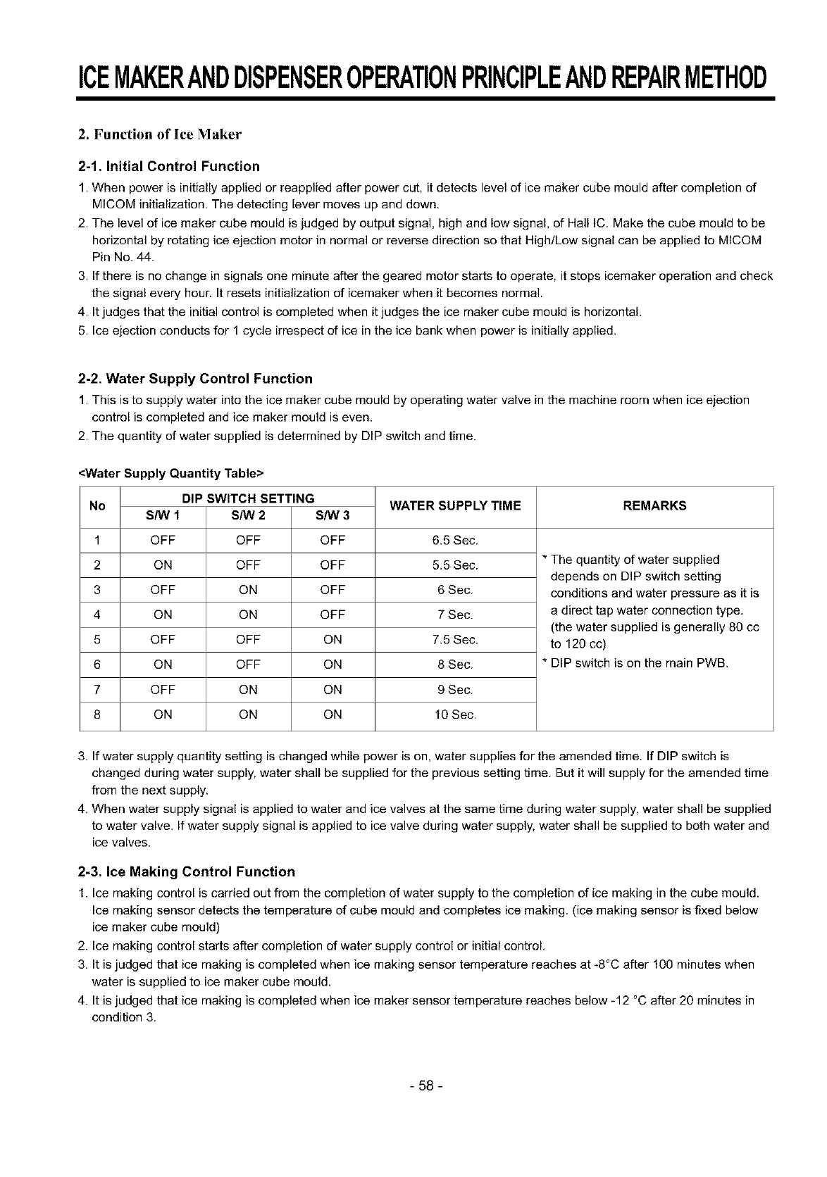
2. The quantity of water supplied is determined by DIP switch and time.
<Water Supply Quantity Table>
DIP SWITCH SETTING
No
1
2
3
4
5
6
7
8
S/W 1
OFF
ON
OFF
ON
OFF
ON
OFF
ON
S/W 2 S/W 3
OFF OFF
OFF OFF
ON OFF
ON OFF
OFF ON
OFF ON
ON ON
ON ON
WATER SUPPLY TIME
6.5 Sec.
5.5 Sec.
6 Sec.
7 Sec.
7.5 Sec.
8 Sec.
9 Sec.
10 Sec.
REMARKS
*The quantity of water supplied
depends on DIP switch setting
conditions and water pressure as it is
a direct tap water connection type.
(the water supplied is generally 80 cc
to 120 cc)
* DIP switch is on the main PWB.
3. If water supply quantity setting is changed while power is on, water supplies for the amended time. If DIP switch is
changed during water supply, water shall be supplied for the previous setting time. But it will supply for the amended time
from the next supply.
4. When water supply signal is applied to water and ice valves at the same time during water supply, water shall be supplied
to water valve. If water supply signal is applied to ice valve during water supply, water shall be supplied to both water and
ice valves.
2-3. Ice Making Control Function
1. Ice making control is carried out from the completion of water supply to the completion of ice making in the cube mould.
Ice making sensor detects the temperature of cube mould and completes ice making. (ice making sensor is fixed below
ice maker cube mould)
2. Ice making control starts after completion of water supply control or initial control.
3. It is judged that ice making is completed when ice making sensor temperature reaches at -8°C after 100 minutes when
water is supplied to ice maker cube mould.
4. It is judged that ice making is completed when ice maker sensor temperature reaches below _12 °C after 20 minutes in
condition 3.
- 58 -
ICEMAKERANDDISPENSEROPERATIONPRINCIPLEANDREPAIRMETHOD
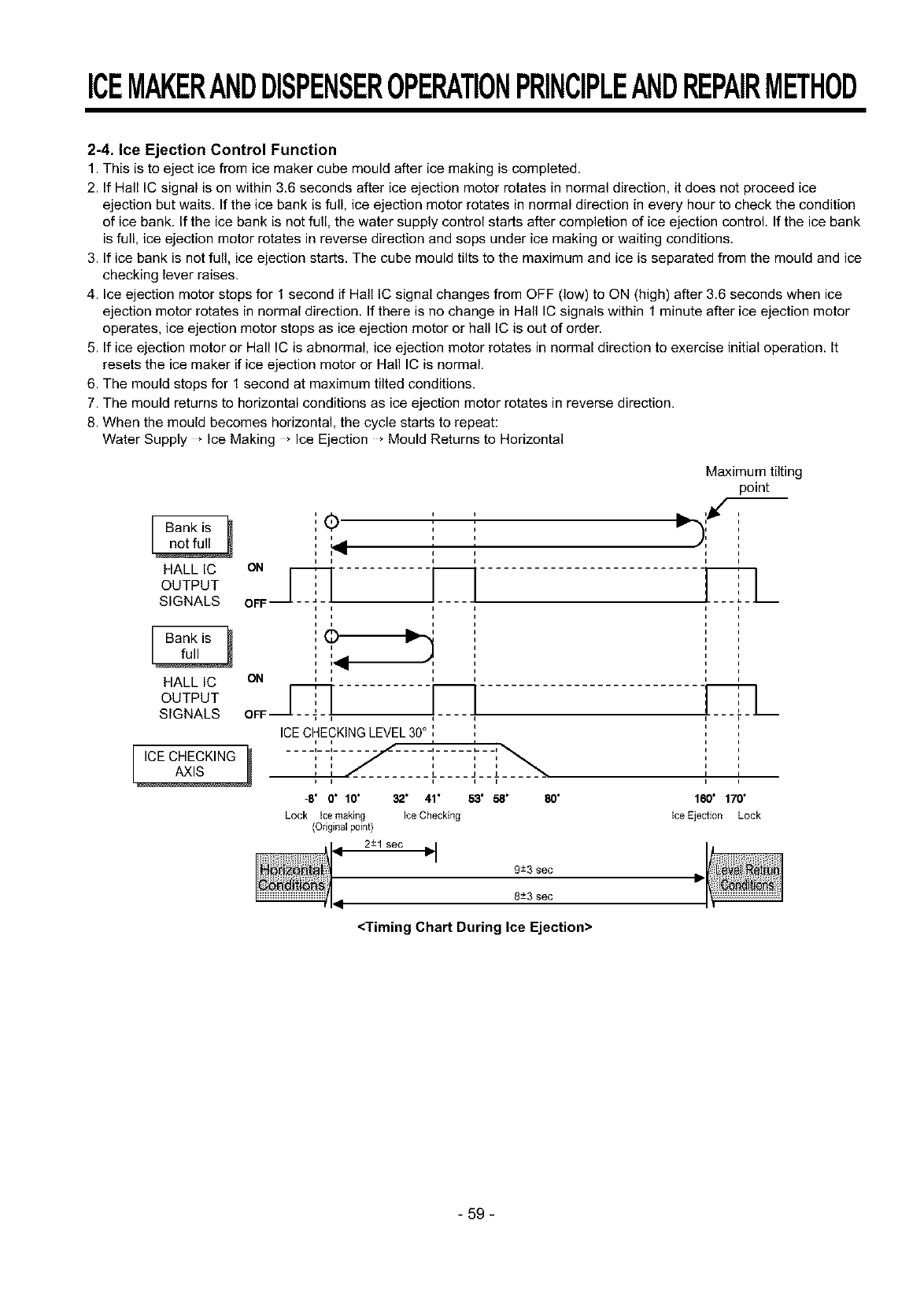
2-4 Ice Ejection Control Function
1. This is to eject ice from ice maker cube mould after ice making is completed.
2. If Hall IC signal is on within 3.6 seconds after ice ejection motor rotates in normal direction, it does not proceed ice
ejection but waits. If the ice bank is full, ice ejection motor rotates in normal direction in every hour to check the condition
of ice bank. If the ice bank is not full, the water supply control starts after completion of ice ejection control. If the ice bank
is full, ice ejection motor rotates in reverse direction and sops under ice making or waiting conditions.
3. If ice bank is not full, ice ejection starts. The cube mould tilts to the maximum and ice is separated from the mould and ice
checking lever raises.
4. Ice ejection motor stops for 1 second if Hall IC signal changes from OFF (low) to ON (high) after 3.6 seconds when ice
ejection motor rotates in normal direction. If there is no change in Hall IC signals within 1 minute after ice ejection motor
operates, ice ejection motor stops as ice ejection motor or hall IC is out of order.
5. If ice ejection motor or Hall IC is abnormal, ice ejection motor rotates in normal direction to exercise initial operation. It
resets the ice maker if ice ejection motor or Hall IC is normal.
6. The mould stops for 1 second at maximum tilted conditions.
7. The mould returns to horizontal conditions as ice ejection motor rotates in reverse direction.
8. When the mould becomes horizontal, the cycle starts to repeat:
Water Supply * Ice Making * Ice Ejection * Mould Returns to Horizontal
'(_ ' ,
[ Bankis _ ', ' '
i' '
i i i
HALL IC ON ' '
OOT OT ICI
SIGNALS OFF
Bank is
HALL IC
OUTPUT
SIGNALS
[,0ECHECK,.G
i
i_ PV _1
ON ,
i i
ICECHECKINGLEVEL30°',
i i i i
.... i_ _1 ........... i ..... l_ _ _1
i i i i i
ii J J J
tii i i
-8" O" 10" 32" 41" 53' 58' 80"
Lock Ice making Ice Checking
(Onginal point)
2-+1 sec _"I
9±3 sec
8±3 sec
Maximum tilting
point
,,)i
I I
160' 170"
ice Ejection Lock
<Timing Chart During Ice Ejection>
59
ICEMAKERANDDISPENSEROPERATIONPRINCIPLEANDREPAIRMETHOD
2-5 Test Function
1. It is to force the operation during operation test, service, and cleaning. The test switch is mounted under the automatic
ice maker. The test function starts when the test switch is pressed for more than 0.5 second.
2. Test button does not work during ice ejection and water supply. It works when it is in the horizontal conditions. If mould is
full of ice during test function operation, ice ejection control and water supply control do not work,
3. When test switch is pressed for more than 0.5 second in the horizontal conditions, ice ejection starts irrespect of the
mould conditions. Water shall be splashed if test switch is pressed before the water in the mould freezes, Water shall be
supplied while the mould returns to the horizontal conditions after ice ejection, Therefore the problems of ice ejection,
returning to the horizontal conditions, and water supply can be checked by test switch, When test function performs
normally, buzzer sounds and water supply shall carry out. Check it for repair if buzzer does not sound.
4. When water supply is completed, the cycle operates normally as follows: lce making _lceejection _Returningto
horizontal conditions * Water supply
5. Remove ice from the ice maker cube mould and press test switch when ice maker cube mould is full of ice as ice ejection
and water supply control do not work when cube mould is full of ice.
2-6. Other functions relating to freezer compartment door opening
1. When freezer door is open, ice dispenser stops in order to reduce noise and ice drop.
2. When freezer door is open during ice ejection and cube mould returning to horizontal condition, ice ejection and cube
mould level return proceed.
3. When freezer door is open, geared motor and cube ice solenoid immediately stop and duct door solenoid stops after 5
seconds.
4. Water dispenser stops in order to protect water drop when freezer door is open.
5. Test function operates normally irrespect of refrigearator compartment door opening.
- 60 -
ICEMAKERANDDISPENSEROPERATIONPRINCIPLEANDREPAIRMETHOD
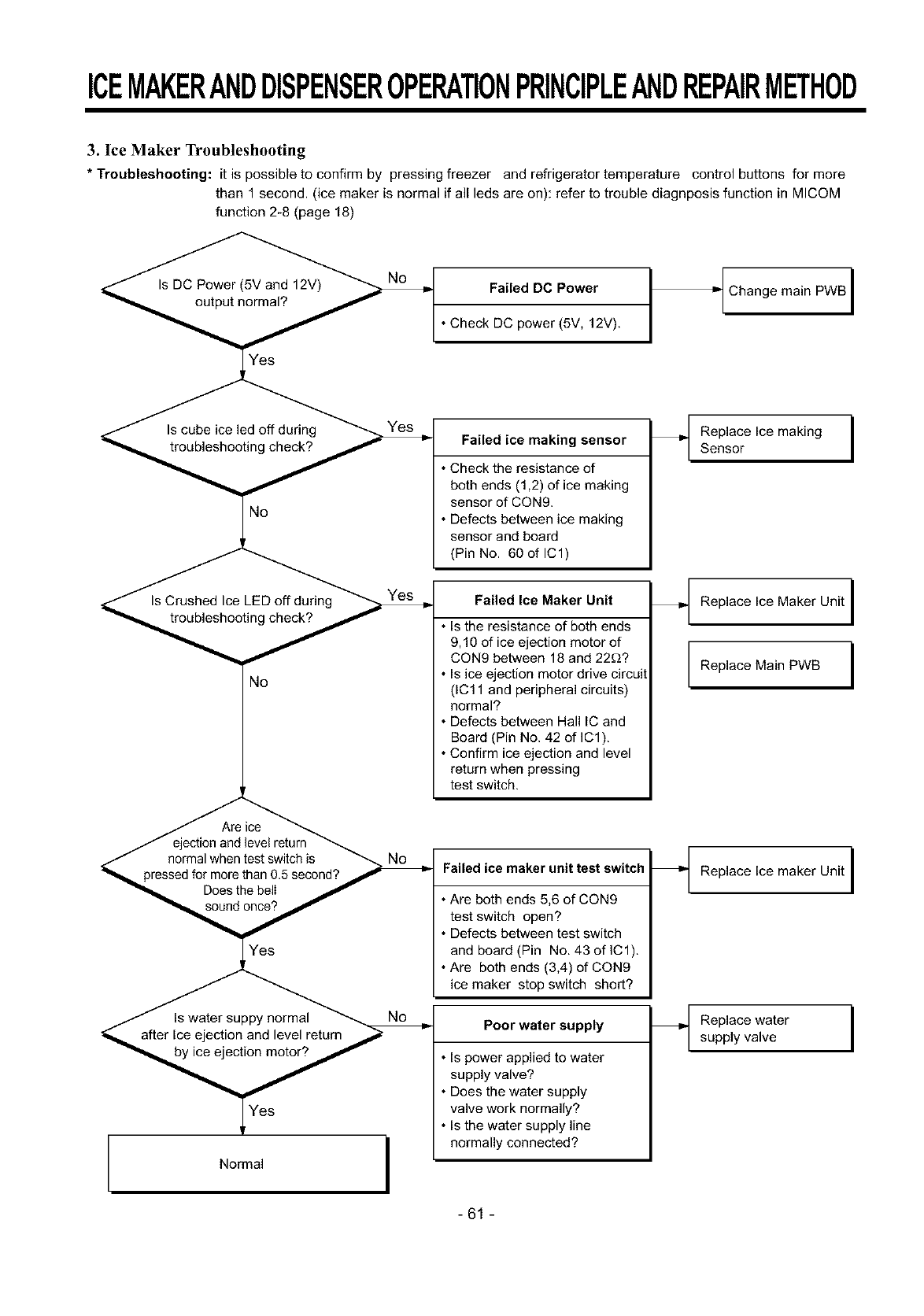
3. Ice Maker Troubleshooting
*Troubleshooting: it is possible to confirm by pressing freezer and refrigerator temperature control buttons for more
than 1 second. (ice maker is normal if all leds are on): refer to trouble diagnposis function in MICOM
function 2-8 (page 18)
No
No
/ejection and level return
_f normal when test switch is
pressed for more than 0_ second? ./" r
Does the belI
Normal
Failed DC Power
• Check DC power (5V, 12V).
Failed ice making sensor
• Check the resistance of
both ends (1,2) of ice making
sensor of CON9.
• Defects between ice making
sensor and board
(Pin No. 60 of IC1)
Failed Ice Maker Unit
• Is the resistance of both ends
9,10 of ice ejection motor of
CON9 between 18 and 22£!?
• Is ice ejection motor drive circuit
(1C11 and peripheral circuits)
normal?
• Defects between Hall [C and
Board (Pin No. 42 of IC1).
• Confirm ice ejection and level
return when pressing
test switch.
Failed ice maker unit test switch
• Are both ends 5,6 of CON9
test switch open?
• Defects between test switch
and board (Pin No. 43 of IC1).
• Are both ends (3,4) of CON9
ice maker stop switch short?
Poor water supply
• Is power applied to water
supply valve?
• Does the water supply
valve work normally?
• Is the water supply line
normally connected?
_t Change main PWB I
Replace Ice making ISensor
Replace Ice Maker Unit I
Replace Main PWB I
Replace Ice maker Unit I
Replace water
supply valve I
-61 -
ICEMAKERANDDISPENSEROPERATIONPRINCIPLEANDREPAIRMETHOD
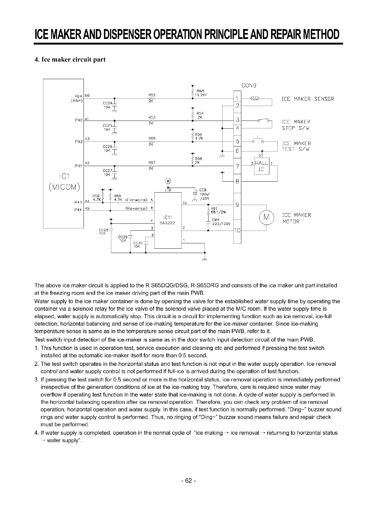
4. Ice maker circuit part
60
P40 41
43
P42
42
P41
IC1
P43
P44
R52
R55
R55
0025
R57
44 47K (For wo_rd)
45 (RevePse)
I
ICll
BA5222
RIM1
1B2KF
<<4_R55
_47K
_2K
_223/100V
CON9
1
2
3
_4
5
7
8
g
IO
ICE MAKER SENSOR
_c_ ICE MAKER
STOP S/W
_I ICE MAKER
2 TEST S/W
ICE MAKER
MOTOR
The above ice maker circuit is applied to the R S65DQG/DSG, R-S65DRG and consists of the ice maker unit part installed
at the freezing room and the ice maker driving part of the main PWB.
Water supply to the ice maker container is done by opening the valve for the established water supply time by operating the
container via a solenoid relay for the ice valve of the solenoid valve placed at the M/C room. If the water supply time is
elapsed, water supply is automatically stop. This circuit is a circuit for implementing function such as ice removal, ice-full
detection, horizontal balancing and sense of ice-making temperature for the ice-maker container. Since ice-making
temperature sense is same as in the temperature sense circuit part of the main PWB, refer to it.
Test switch input detection of the ice-maker is same as in the door switch input detection circuit of the main PWB.
1. This function is used in operation test, service execution and cleaning etc and performed if pressing the test switch
installed at the automatic ice-maker itself for more than 0.5 second.
2. The test switch operates in the horizontal status and test function is not input in the water supply operation. Ice removal
control and water supply control is not performed if full-ice is arrived during the operation of test function.
3. If pressing the test switch for 0.5 second or more in the horizontal status, ice removal operation is immediately performed
irrespective of the generation conditions of ice at the ice-making tray. Therefore, care is required since water may
overflow if operating test function in the water state that ice-making is not done. A cycle of water supply is performed in
the horizontal balancing operation after ice removal operation. Therefore, you can check any problem of ice removal
operation, horizontal operation and water supply. In this case, if test function is normally performed, "Ding-" buzzer sound
rings and water supply control is performed. Thus, no ringing of "Ding-" buzzer sound means failure and repair check
must be performed.
4. If water supply is completed, operation in the normal cycle of "ice making * ice removal * returning to horizontal status
water supply".
- 62 -
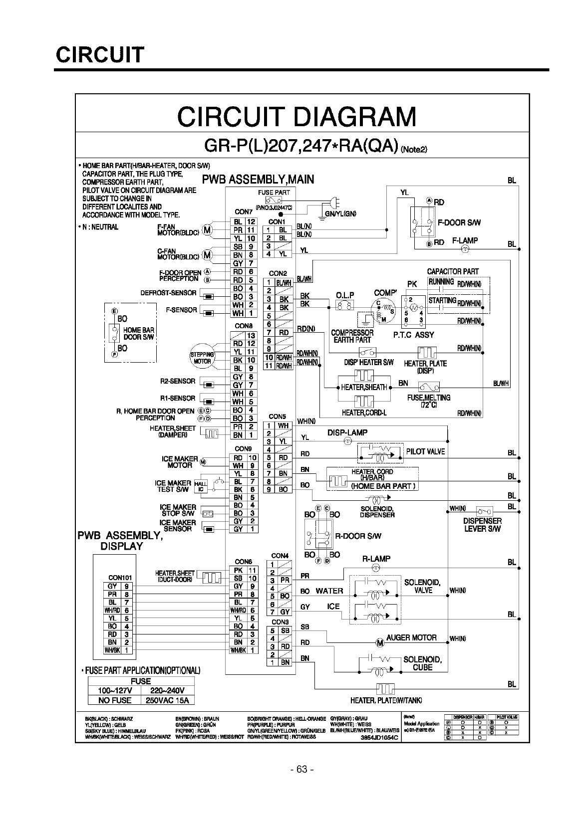
CIRCUIT
CIRCUIT DIAGRAM
GR-P(L)207,247*RA(QA)(No,e2_
•HOMEBAR PART(H/BAR-HEATER,DOOR
CAPACITORPART,1HE PLUGTYPE,
COMPRESSOREARTHPART,
PILOTVALVEON CIRCUITDIAGRAMARE
SUBJECTTOCHANGE IN
DIFFERENTLOCALITESAND
ACCORDANCEWITH MODELTYPE.
•N:NEUTRAL F-FAN
C-FAN
MOTOR(BLDC)
PERCEPTION
DEFROST.SENSOR
F® ] _-SENSOR
HOMEBAR
DOORS/W
L_S° I
I_ENSOR
RI"SENSOR
R, PERCEPTION
HEA]ERSHEET
DAMPER E
ICE MAKER
MOTOR
ICE MAI_R
TEST S/W
ICE MAKER
STOPS/W
ICE MAKER
SENSOR
PWB ASSEMBLY,
DISPLAY
HEATERSHEET
CONlOl {DUCT-i_P.)_
GY g
PR 8
BL 7
_5
BO 4
RD 3
BN 2
PWB ASSEMBLY,MAIN
FUSE PART
IP,_IO;N_447Q
GON7 _
_N4
CO _
SB _
GY = _"
PR
CON3
RD
YL
YL
BK
K
)(N)
WH_)
CAPACITORPART
PK [RUNNINGRD/WH(I__
O.L.P COMP' __ !
COMPRESSOR P.T.C ASSY
EARTHPART
RD/WHIN,
DISP'HEAIERS/W HEATERPLA'_
(DI_P)
_ING
172_C1
HEK_R,CORD-L RD/WH(N
_(N)
DISP-LAMP
YL _ - •
o _,%N%
R-DOOR S/W
BO<__BO R-LAMP
_WAIE
GY
SB
_ _SOLENO,O,
_ _ _ CUBE
•FUSEPARTAPPLICATION(OPTIONAL)
FUSE
100-127V 220-240V
NO FUSE 2SOVAC 15A HEATER,PLATE(WfFANIg
BK(BLa_ClO:_I'IWARZ BN(BRO1M_:BRAUN BC(BRIQHT_ANQE_:PIB,.L_I_E QY(QRAYJ:QI:L_J _1_¢_
"tl_OW) ; GELB GN(G P,I_J_ : GRON PR(PIJRPL_ : PIJRFtJR WH(lh_FT_) : WEISS Mod_ Agplimi_on
3B(SKy BLUE) : HIMMEUBLALI pK(PINK_ : ROSA GN/YL(GREENHELLOW) ;GRON/GELB BL_.H ( BLUFJWHIT_ ; BLALIp,_EIS
WI'_BK_hl_I_c_BL_CK_: WEISS/ScI'_/ARz WH/F'I]ONHI_JRED):WEI88_ROT R_WH(RE_ITE_: ROTh'_EIS_ 3854JD1054C
BL
BL
BL
BI
BI
DISPENSER
LEVERS/W
BL
WH_
B[
NH_
BL
-63 -
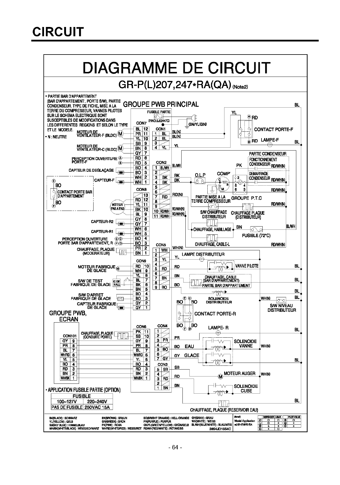
CIRCUIT
DIAGRAMME DE CIRCUIT
GR-P(L)207,247*RA(QA)(No,e2
• PARTIEBARD'APPARTEMENT
BARD'APPARTEMENT:,PORTES/W),PARRE
CONDENSEUR,TYPEDERCHE, MISEALA GROUPEPWB PRINCIPAL
TERREDUCOMPRESSEUR,VANNESPILOTES
SURLESCHEMAELECTRIQUESONT
SUSCEPTIBLESDEMODIFICATIONSDANS
LESDIFFEREN_SREGIONSETSELONLETYPE
ETLEMODELE.MO'i_URDE
• N:NEU_E VENTILATEUR-F
MO'IEUR DE
VENTILATEUR-C
PORTE-F
CAPTEURDEDEGLA_AGEI
CAPTEUR-F
°
CONTACTPOLITEBAR
D'APP_MENT
0
CAP_UR-R1
PERCEPTION OUVERTURE
POR'_ BAR D'APPARTEMENT, R I
CHAUFFAGE, PLAQUE
(MODERA]EUR)
DE GLACE
ShV DETEST
FABRIQUEDEGLACE
ShV D'ARRET
FABRIQUEDE GLACE
CAPTEURFABRIQUE
DE GLACE
GROUPE PWB,
ECRAN
CHAUFFAGEPLAQUE
CON101 (CONDUIT_PORTE)
GY 9
PR 8
BL 7
_5
BO 4
RD 3
BN 2
FUSIBLEP,_nE
(P,_IO;N_!47Q
CON7 _L(GN)
YL
O.L.P
CON6 _N4
SB
GY _
PR ....
CON3
RD _
BN .
COMP'
LAMPEDISTRIBUTEUR
YL __•
RD f_i VANNEPILO"_
o o,,_%"_-_R
CONTACT PORTE-R
BO_ _BO LAMPE- R
PR _ _ SOLENOIDE
SB
_ _/_ SOLENOIDE
OUBE
BL
YL
CONTACT PORTE-F
PAR11ECONDENSEUR
IFONC_NNEMENT
PK :CONDENSEURRD/WH_)
F
•APPLICA1]ONFUSIBLEPARTIE(OPTION)
I_FUSIBLE 1
PASDE FUSIBLE 250VAC 15A CHAUFFAGE,PLAQUE(RESERVOIREAU)
BV,(BIACIO:SCI'IWARZ BN(BROWT_:BRAUN BG(BRIQHTOP,ANQE):HB..L43RANQEQY(QRAYJ:QP,NJ _P,_G_¢"_ A
"fl4"f_LOW):GELB GN(GP,I_J4):GRON PR(FIJRPt_:FIJRPUR WH0hl"II_):WEISS Mod_Applirai_n
,3B($KYBLUE): HIMMEUBLAU pIqPINiq: ROSA GNHL(GREENrfELLOW):GRO'N_ELB BL_H(BLUE,It_IT_) :BLAU_WEIS
WI'I,_,(Ohl"fl1_=,f_J_Q_:lh_ISS/_CI':Wi_ZWH/F,OONHI_ED):WEI88_ROT R_WH(REON_ITE_:ROTN_EIS_ US54JDI054C
RD/WHOql
BL
BI
BI
S_/VNIVEAU
DISTRIBUTEUR
BL
WH_
B[
NH_
BL
-64 -
TROUBLE DIAGNOSIS
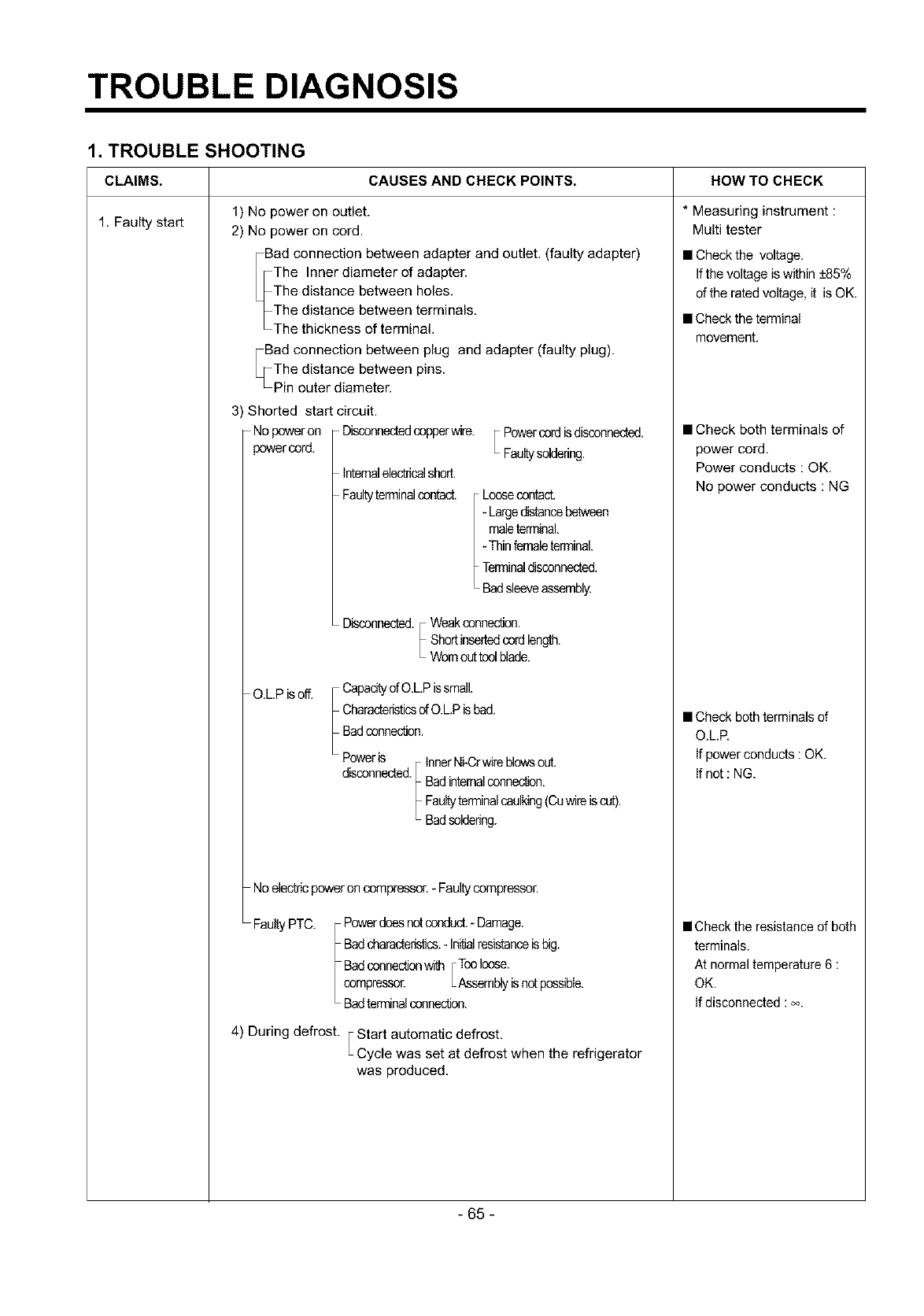
1. TROUBLE SHOOTING
CAUSES AND CHECK POINTS. HOW TO CHECKCLAIMS.
1. Faulty start 1) No power on outlet.
2) No power on cord.
Bad connection between adapter and outlet. (faulty adapter)
The Inner diameter of adapter.
The distance between holes.
The distance between terminals.
The thickness of terminal.
Bad connection between plug
The distance between pins.
Pin outer diameter.
3) Shorted start circuit.
Nopoweron Disconnectedcopperwire.
powercord.
and adapter (faulty plug).
Internalelsotncalshort.
Faultyterminalcontact.
Powercordisdisconnected.
Faultysoldering.
Loosecontact,
Largedistancebetween
maleterminal,
- Thinfemaleterminal.
Terminaldisconnected,
Badsleeveassembly.
Disconnected. Weakconnection.
Shortinsertedcordlength.
Wornouttoolblade.
O.L.P isoff. CapacitydO.LP issmall.
CharacteristicsofO.L.Pisbad.
Badconnection.
Poweris InnerNi-Crwireblowsout.
disconnected. Badinternalconnect.
Faultyterminalcaulking(Cawireis cut).
Badsoldering.
Noelectricpoweron compressor.- Faultycompressor.
FaultyPTC. Powerdoesnot conduct.- Damage.
Badcharacteri_cs._Initialresistanceisbig.
Badconnectionwith _TooIcose.
compressor. LAssemblyisnotpossible.
Badterminalconnection.
4) During defrost. FStart automatic defrost,
LCycle was set at defrost when the refrigerator
was produced.
*Measuring instrument :
Multi tester
• Check the voltage.
If the voltage iswithin +85%
of the rated voltage, it is OK.
• Check the terminal
movement.
• Check both terminals of
power cord,
Power conducts : OK.
No power conducts : NG
• Check both terminals of
O.LR
If power conducts : OK.
If not : NG.
• Check the resistance of both
terminals.
At normal temperature 6 :
OK.
If disconnected : oo.
- 65-
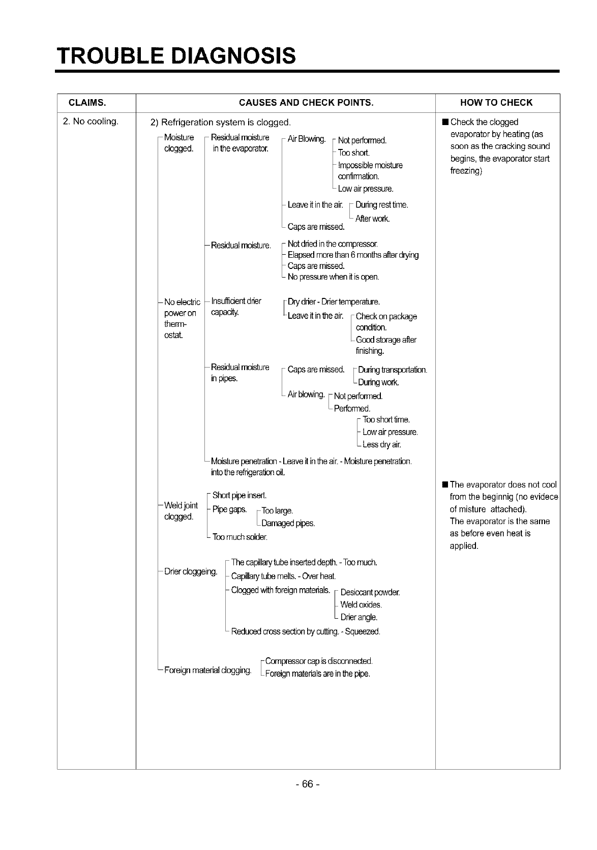
TROUBLE DIAGNOSIS
CLAIMS, CAUSES AND CHECK POINTS. HOW TO CHECK
2. No cooling. 2) Refrigeration system is clogged.
Moisture Residualmoisture Air Blowing. Notperformed.
dogged, intheevaporator. Tonshort.
impossiblemoisture
confirmation.
Lowairpressure.
Leaveitintheai_ _ Dufingresttime.
• Afterwork.
Capsaremissed.
Residualmoisture. Notdriedinthecompresse_
Elapsedmorethan6 monthsafterdt_ng
Capsaremissed.
Nopressurewhenitis_n.
Noelectric
power on
therm-
ontat.
Insuffidentdrier [ Drydrier- Drlertemperature.
capadty Leaveitinthe air. Checkon package
condition.
Goodstorageafter
finishing.
Residuaimoisture
inpipes. Capsaremissed. _Duringtransporta_.
• Duringwork.
Airblowing._ Not_fformed.
•Performed.
Tonshorttime.
Lowairpressure.
Lessdryair.
Moisturepenetra_ - Leaveitintheair.- Moisturepenetration.
intotherefrigerationoil.
Weldjoint
dogged.
Shortpipeinsert.
Pipegaps. FTonlarge,
LDamagedpipes.
Tonmuchsolder.
Drierdoggeing. Thecapillarytubeinserteddepth.- Tonmuch.
Capillarytubemelts.- Overheat.
Cloggedwithforeignmaterials. Desiccantpowder.
Weldoxides.
Drierangle.
Reducedcrosssectionbycutting.- Squeezed.
Compressorcap isdisconnected.
Foreignmaterialclogging. Foreignmaterialsare inthepipe.
• Check the clogged
evaporator by heating (as
soon as the cracking sound
begins, the evaporator start
freezing)
• The evaporator does not cool
from the beginnig (no evidece
of misture attached).
The evaporator isthe same
as before even heat is
applied.
- 66 -
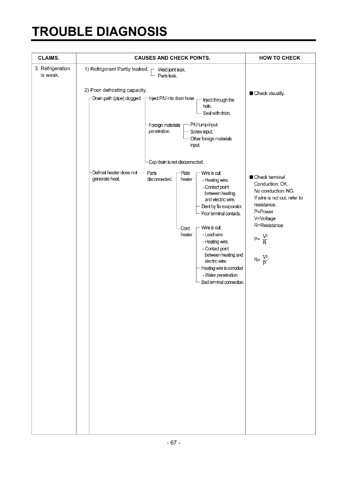
TROUBLE DIAGNOSIS
CLAIMS.
3. Refrigeration
is weak.
CAUSES AND CHECK POINTS.
1) Refrigerant Partly leaked. • Weldjointleek.
Partsleak.
2) Poor defrosting capacity.
Drainpath (pipe)clogged. InjectP/Uintodrainhose. Injectthroughthe
hole.
Sealwithdrain.
Foreignmaterials P/Ulumpinput.
penetration. Screwinput.
Otherforeignmaterials
input.
Capdrainis notdisconnected.
Defrostheaterdoesnot Parts
generateheat. disconnected.
Plate
heater
Wireis cut.
- Heatingwire.
- Contactpoint
betweenheating
andelectricwire.
Dentbyfinevaporator,
Poorterminalcontacts.
Cord Wireis cut.
heater - Leadwire.
- Heatingwire.
- Contactpoint
betweenheatingand
electricwire.
Heatingwireiscorroded
-Waterpenetration.
Badterminalconnection.
HOW TO CHECK
• Check visually.
• Check terminal
Conduction: OK.
No conduction: NG.
If wire is not cut, refer to
resistance.
P=Power
V=Voltage
R=Resistance
R
V2
R = --
P
- 67 -
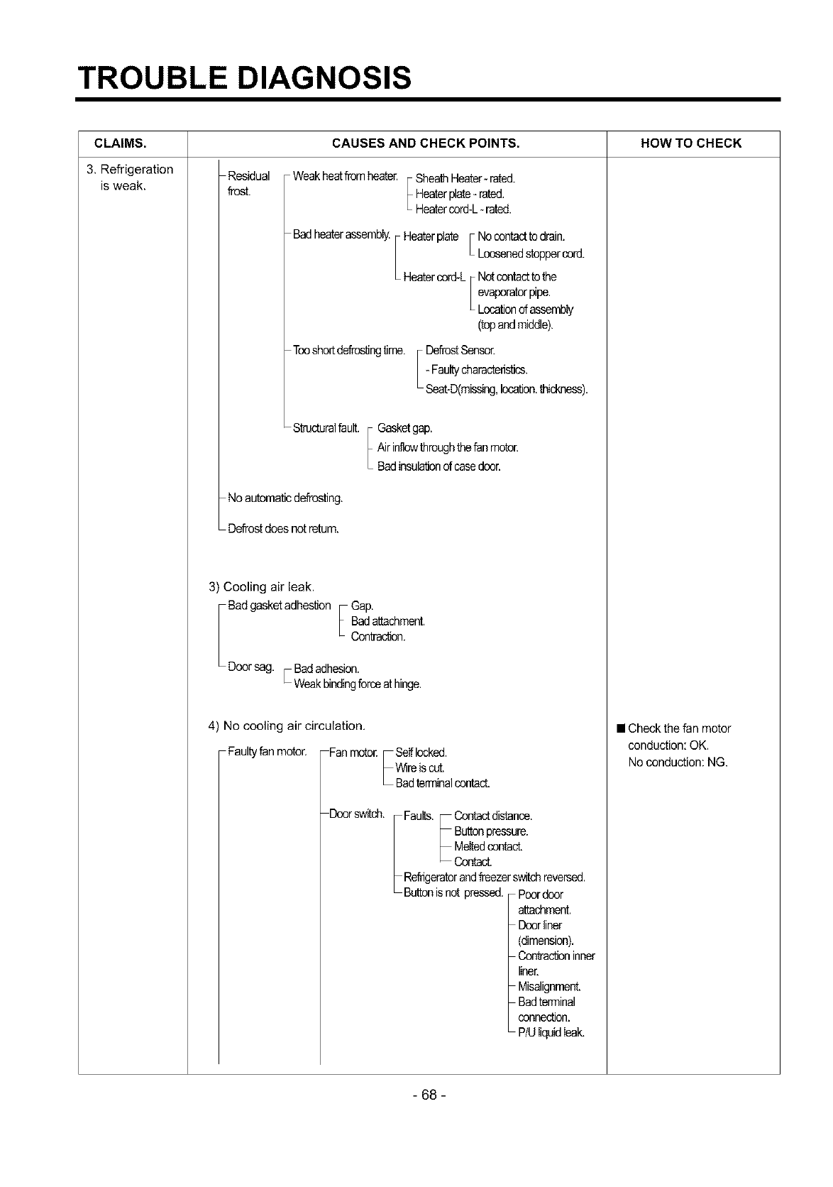
TROUBLE DIAGNOSIS
CLAIMS.
3. Refrigeration
is weak.
CAUSES AND CHECK POINTS. HOW TO CHECK
Residual
frost. Weakhe_ from heate_ SheathHeater- rated.
Heaterplate- rated,
Heatercord-L- rated.
Badhe_er assembly. He_er plate F Nocontactto drain.
L Loosenedstoppercord.
He_er cord-L Notcontactto the
evaporatorpipe.
Locationof assembly
(topandmiddle).
Toosheddefrostingtime. DefrostSensor.
- Faultycharacteristics.
Seat-D(missing,location,thickness).
SthJcturalfault. Gasketgap.
Airinflowthroughthefanmotor.
Badinsulationof casedoor.
No automaticdefrosting.
Defrostdoes notretum.
3) Cooling air leak.
Bad gasketadhestion Gap.
Badattachment.
Contract.
Door sag. r Badadhesion.
Weakbindingforce_ hinge.
4) No cooling air circulation.
Faultyfan motor. Fanmotor. Selflocked.
Wireis cut.
Badterminalcontact.
Doorswitch. Faults. Contactdistance.
Buttonpressure.
Meltedcontact.
Contact.
Refrigeratorandfreezerswitchreversed.
Buttonisnot pressed. Poordoor
attachment.
Doorliner
(dimension).
Contractioninner
liner.
Misalignment
Badterminal
sennection.
P/Uliquidleak.
• Check the fan motor
conduction: OK.
No conduction: NG.
- 68 -
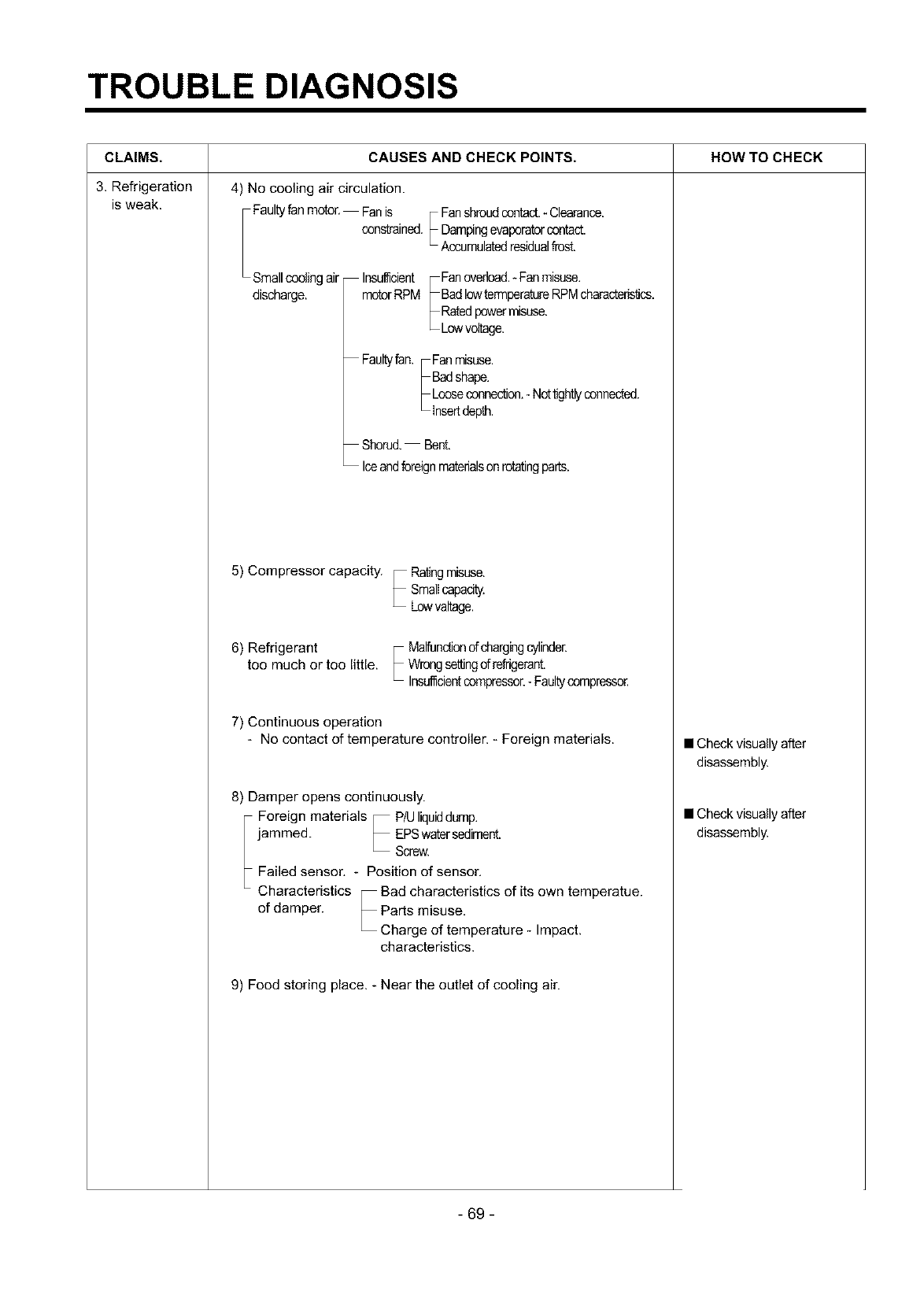
TROUBLE DIAGNOSIS
CLAIMS.
3. Refrigeration
is weak.
CAUSES AND CHECK POINTS. HOW TO CHECK
4) No cooling air circulation.
Faultyfan motor, Fanis F Fanshroudcontact.- Clearance.
constrained,_ Dampingevaporatorcontact.
L Accumul_edresidualfrost.
Smallcoolingair
discharge.
Insufficient Fanoverload.- Fanmisuse.
motorRPM BadlowtermperatureRPMcharacteristics.
Ratedpowermisuse.
Lowvoltage.
Faultyfan. Fanmisuse.
Badshape.
Looseconnection.- Nottightlyconnected.
insertdepth.
Shorud. Bent.
Iceandforeignm_edalsonrotatingparts.
5) Compressor capacity. Ratingmisuse.
Smallcapacity.
Lowvaltage.
6) Refrigerant
toomuch or toolittle. Malfunctionofchargingcylinder.
Wrongsettingdrefrigerant.
Insufficientcompressor.- Faultycempresse_
7) Continuous operation
- No contact of temperature controller. - Foreign materials.
8) Damper opens continuously.
Foreign materials P/Uliquiddump.
jammed. EPSwd(ersediment.
Screw.
Failed sensor, - Position of sensor,
Characteristics Bad characteristics of its own temperatue.
of damper. Parts misuse,
Charge of temperature - Impact.
characteristics.
9) Food storing place. - Near the outlet of cooling air.
• Check visually after
disassembly.
• Check visually after
disassembly.
- 69 -
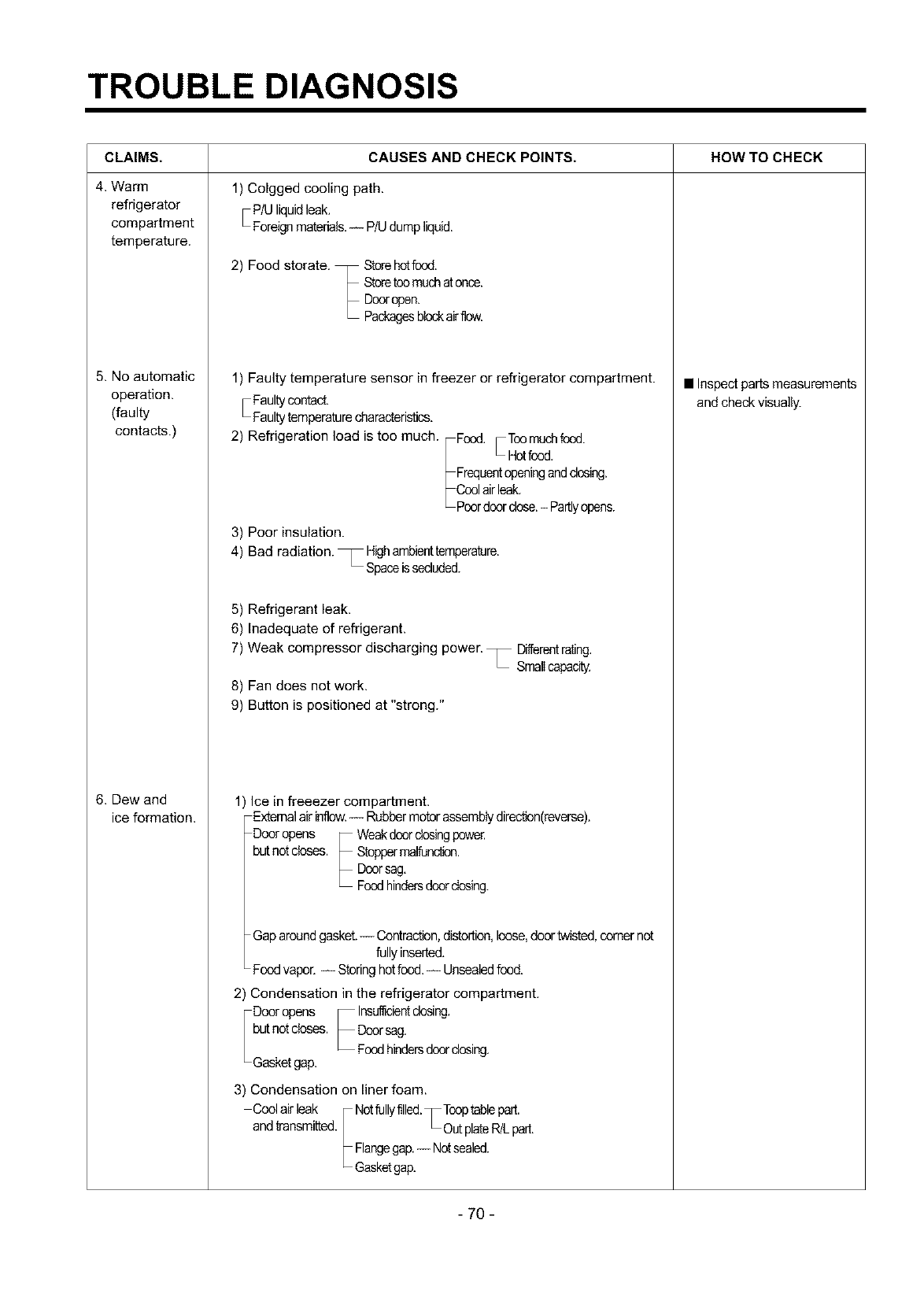
TROUBLE DIAGNOSIS
CLAIMS. HOW TO CHECK
4. Warm
refrigerator
compartment
temperature.
5. No automatic
operation.
(faulty
contacts.)
6. Dew and
ice formation.
CAUSES AND CHECK POINTS,
1) Colgged cooling path.
• P/U liquidleak.
Foreignmatepals.-- P/Udumpliquid.
2) Food storate. Storehotfond.
Storetonmucha'conce.
Dooropen.
Packagesblockairflow.
1) Faulty temperature sensor in freezer or refrigerator compartment.
Faultycontact.
Faultytemperaturecharacteristics.
2) Refrigeration load is too much. Food. ,Tonmuchfond.
_Hot foed.
Frequentopeningandclosing.
Coolairleak.
Poordoordose.- Partlyopens.
3) Poor insulation.
4) Bad radiation. _ Highambiesttemparature.
L Spaceissecluded.
5) Refrigerant leak.
6) Inadequate of refrigerant.
7) Weak compressor discharging power. • Differentrating.
Smallcapacity.
8) Fan does not work.
9) Button is positioned at "strong."
1) Ice in freeezer compartment.
Extemalairinflow.-- Rubbermotorassemblydirection(reverse).
Door opens Weakdoordosingpowe£
but notcloses. Stoppermalfundion.
Doorsag.
Foodhindersdoordosing.
Gap aroundgasket.-- Contraction,distortion,loose,doortwisted,comer not
fullyinserted.
Food vapor. -- Storinghotfood.-- Unsealedfond.
2) Condensation in the refrigerator compartment.
Door opens Insufficientdosing.
but notcloses. Doorsag.
Foodhindersdoordosing.
Gasketgap.
3) Condensation on liner foam.
Conl airleak Notfullyfilleq., Tonptablepart.
and transmitted. Out plateR/Lpart.
Flangegap.-- Notsealed.
Gasketgap.
• Inspect parts measurements
and check visually.
- 70 -
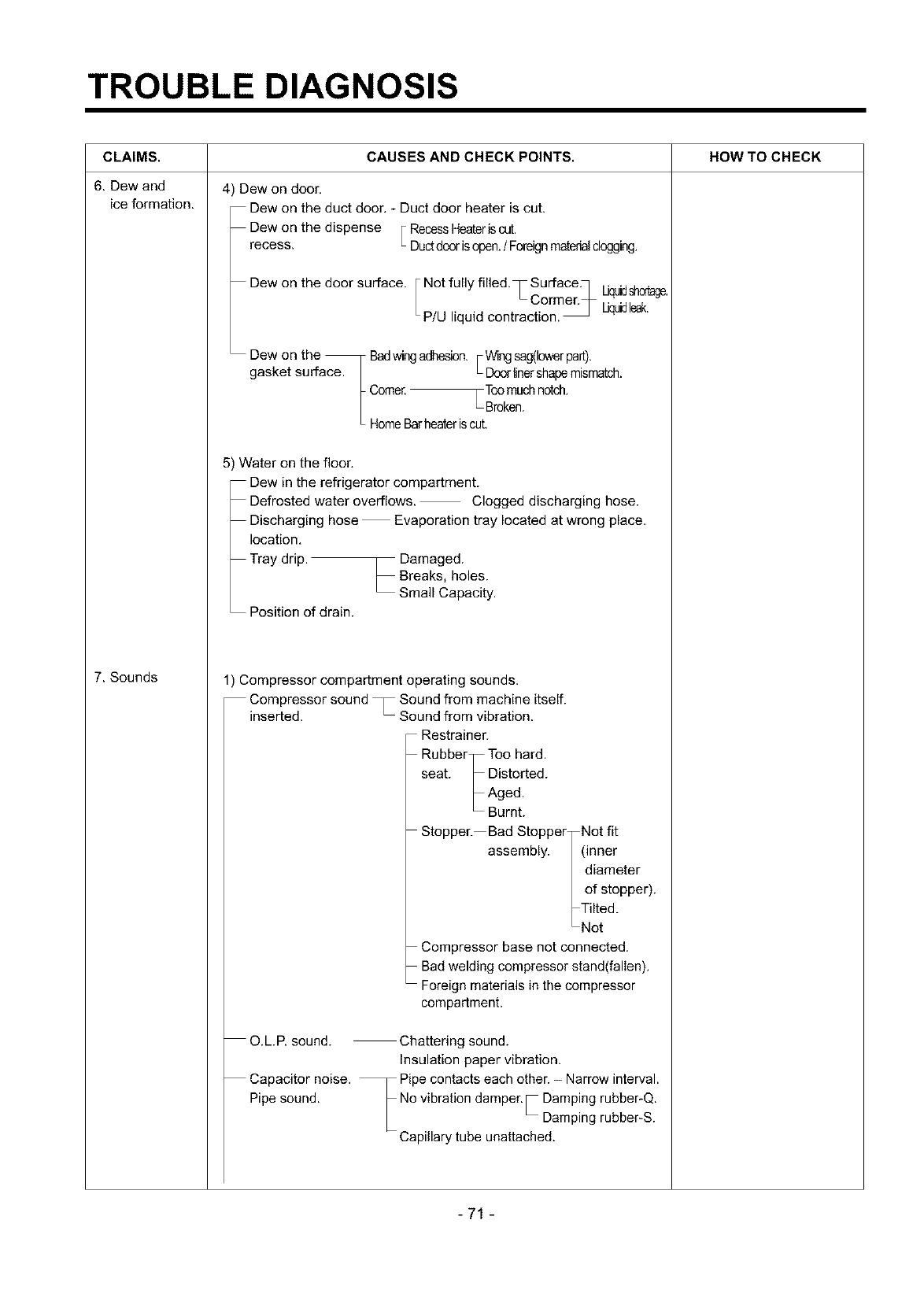
TROUBLE DIAGNOSIS
CLAIMS.
6. Dew and
ice formation.
7. Sounds
CAUSES AND CHECK POINTS.
4) Dew on door.
Dew on the duct door. - Duct door heater is cut.
Dew on the dispense F RecessHeateriscut.
recess. L Ductdoorisopen./Foreignmaterialdogging.
Dew on the door surface. Not fully filled. T Surface.]
L Cormer_ IJquidshort,e.
P/U liquid contraction. _ IJquidleak.
Dew on the Badwingadhesion. FWingsag(Iowerpart).
gasket surface. • Doorlinershapemism_ch.
Come£ FToo muchnotch.
• Broken.
HomeBarheateris cut.
5) Water on the floor.
Dew in the refrigerator compartment.
Defrosted water overflows. Clogged discharging hose.
Discharging hose Evaporation tray located at wrong place.
location.
Tray drip. Damaged.
Breaks, holes.
Small Capacity.
Position of drain.
1) Compressor compartment operating sounds.
Compressor sound _ Sound from machine itself.
inserted. _ Sound from vibration.
Restrainer.
Rubber Too hard.
seat. Distorted.
Aged.
Burnt.
Stopper. Bad Stopper Not fit
assembly. (inner
diameter
of stopper).
Tilted.
Not
Compressor base not connected.
Bad welding compressor stand(fallen),
Foreign materials in the compressor
compartment.
O.L.E sound. Chattering sound.
Insulation paper vibration.
Capacitor noise. Pipe contacts each other. - Narrow interval.
Pipe sound. No vibration damper,_ Damping rubber-Q,
Damping rubber-S.
Capillary tube unattached.
HOW TO CHECK
-71 -
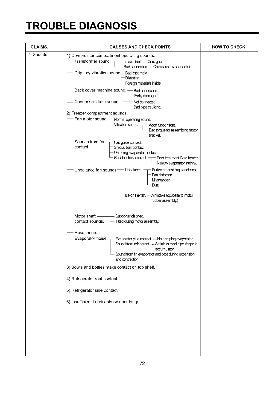
TROUBLE DIAGNOSIS
CLAIMS. CAUSES AND CHECK POINTS. HOW TO CHECK
7. Sounds 1) Compressor compartment operating sounds.
Transformer sound. _lts ow_fault.-- Coregap.
Badconnection.-- Correctscrewconnect.
Drip tray vibration sound Badassembly.
Distortion.
Foreignmaterialsinside.
Back cover machine sound. T Badconnection.
Partlydamaged.
Condenser drain sound. _ Notconnected.
hBadpipecaulking.
2) Freezer compartment sounds.
Fan motor sound. • Normaloperatingsound.
L Vibrationsound._ Aged rubbersedc,
Badtorqueforassemblingmotor
bracket.
Sounds from fan Fanguidecontact.
contact. Shroudburrcontact.
Dampingevaporatorcontact.
Residualfrostcontact._ PoortreatmentCordheater.
LNarrowevaporatorinterval.
Unbalance fan sounds_ Unbalance. Surfacemachiningconditions.
Fandistortion,
Misshappen.
Burr.
Iceonthefan.-- Air intake(oppositeto motor
rubberassembly.)
Motor shaft _ Supporterdiso_ted.
contact sound_ _ TiIteddaringmotorassembly.
Resonance.
Evaporator noise. Evaporatorpipecontact.-- Nodampingevaporator
Soundfromrefrigerant.-- Stainlesssteelpipeshapein
accumulator.
Soundfromfin evaporatorandpipeduringexpansion
andcontraction.
3) Bowls and bottles make contact on top shelf.
4) Refrigerator roof contact.
5) Refrigerator side contact.
6) Insufficient Lubricants on door hinge.
- 72 -
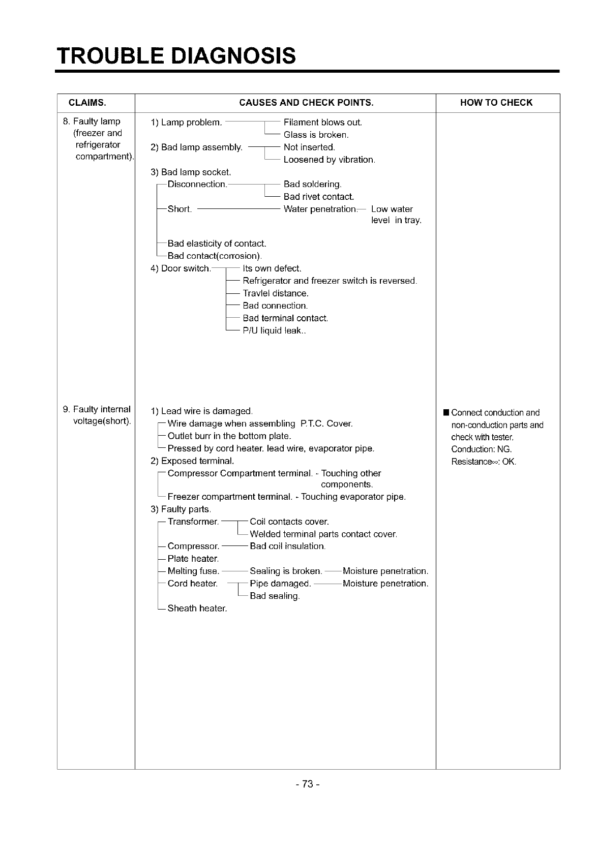
TROUBLE DIAGNOSIS
CLAIMS. HOW TO CHECK
8. Faulty lamp
(freezer and
refrigerator
compartment).
9. Faulty internal
voltage(short).
1) Lamp problem.
2) Bad lamp assembly.
3) Bad lamp socket.
CAUSES AND CHECK POINTS.
,Filament blows out.
Glass is broken.
.Not inserted.
Loosened by vibration.
Disconnection._ Bad soldering.
Bad rivet contact.
Short. Water penetration_ Low water
level in tray.
Bad elasticity of contact.
Bad contact(corrosion).
4) Door switch. Its own defect.
Refrigerator and freezer switch is reversed.
Travlel distance.
Bad connection.
Bad terminal contact.
P/U liquid leak..
1) Lead wire is damaged. • Connect conduction and
Wire damage when assembling RT.C. Cover.
Outlet burr in the bottom plate.
Pressed by cord beaten lead wire, evaporator pipe.
2) Exposed terminal.
Compressor Compartment terminal. - Touching other
components.
Freezer compartment terminal. - Touching evaporator pipe.
3) Faulty parts.
Transformer. _ Coil contacts cover.
Welded terminal parts contact cover.
Compressor. Bad coil insulation.
Plate heater.
Melting fuse. Sealing is broken. Moisture penetration.
Cord heater. _Pipe damaged. Moisture penetration.
Bad sealing.
Sheath heater.
non-conduction parts and
check with tester.
Conduction: NG.
Resistances: OK.
- 73 -
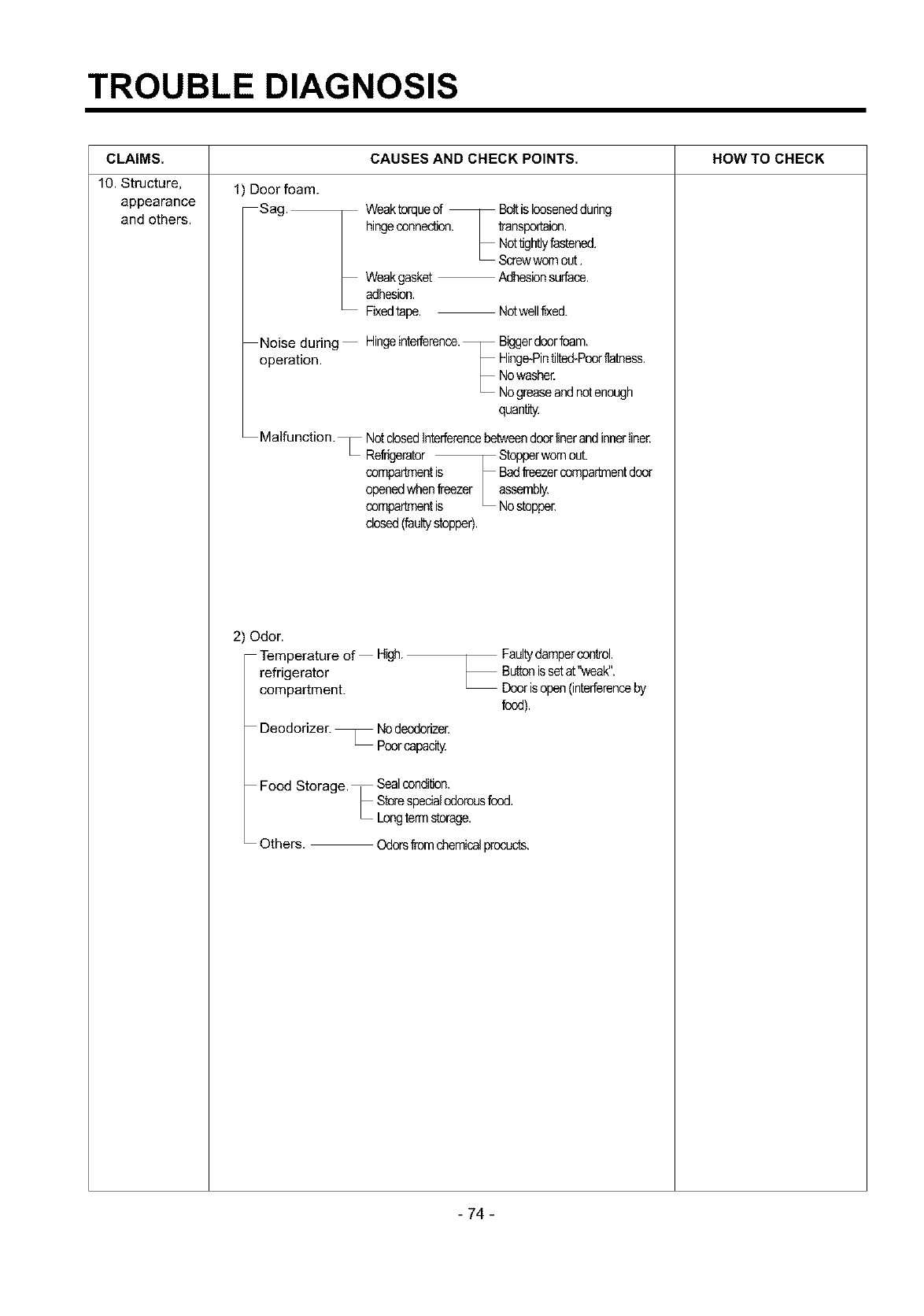
TROUBLE DIAGNOSIS
CLAIMS.
10. Structure,
appearance
and others.
CAUSES AND CHECK POINTS. HOW TO CHECK
1) Door foam.
Sag. Weaktorqueof Bo_is looseneddunng
hingeconnection, transporfaien.
Nottightlyfastened.
Screwwornout.
Weakgasket AdhesionsurPace.
adhesion.
Fixedtape. Netwelltixed.
Noise during Hingeinterference. Biggerdoorfoam.
operation. Hinge-Pintilted-Poorflatness.
Nowasher.
Nogreaseandnotenough
quantity.
Malfunction. _ NotdosedInterferencebetweendoorlinerand innerIine_
Refrfgerater Stopperwornout.
compartmentis
openedwhenfreezer
compartmentis
closed(faultystopper).
2) Odor.
Temperature of High.
refrigerator
compartment.
Deodorizer. _ Nodeedonzer.
Poorcapacity.
Bad_eezercompedmentdoor
assembly.
Nostopper.
Faultydampercontrol.
Buttonissetat"weak".
Doorisopen(interferenceby
food).
Food Storage. Sealcondition.
Storespecialodorousfood.
L Longtermstorage,
Others. Odorsfromchemicalprocacts.
- 74 -
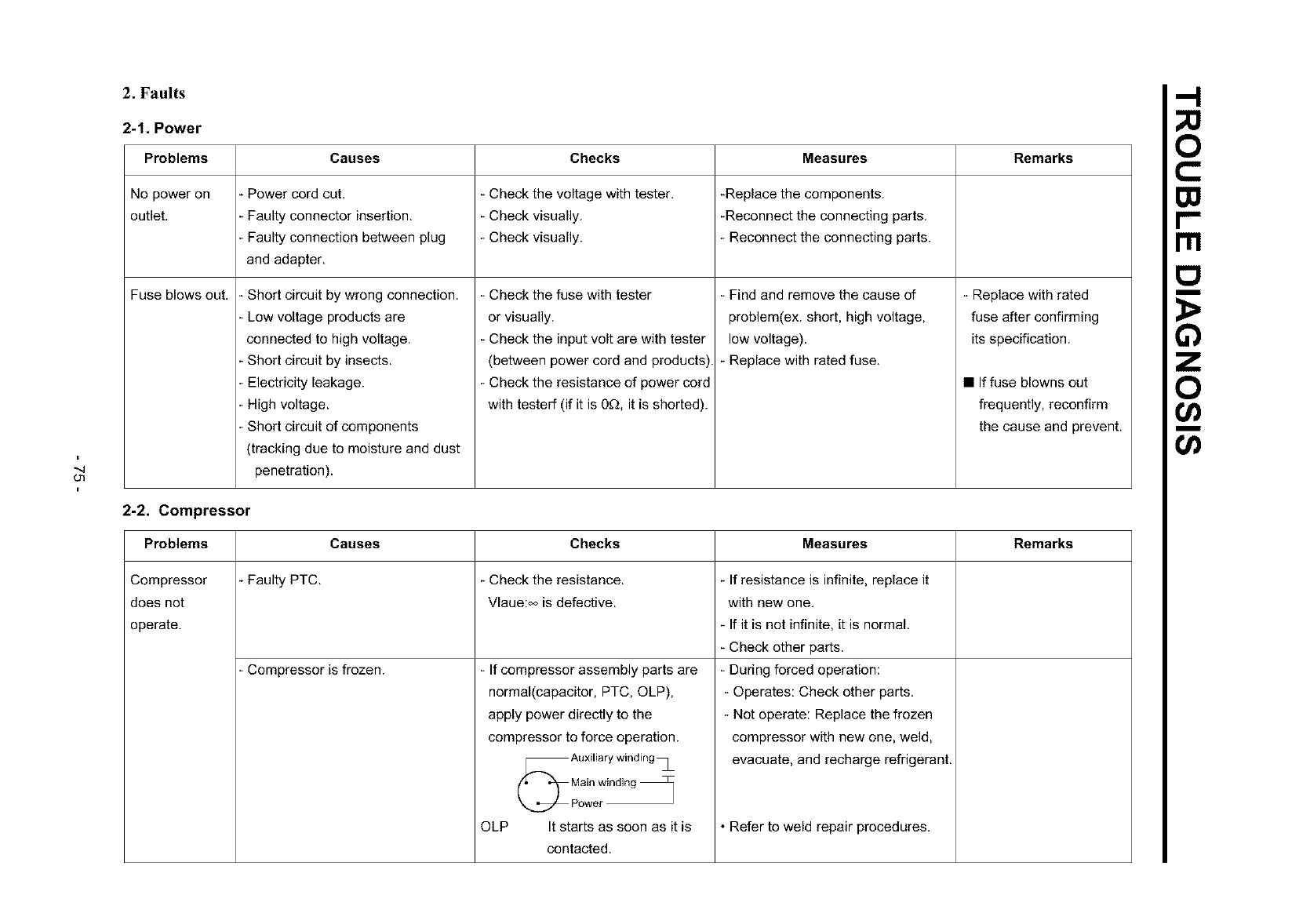
"-4
O1
2. Faults
2-1. Power
Problems Causes Checks Measures Remarks
No power on -Power cord cut. - Check the voltage with tester. -Replace the components.
outlet. - Faulty connector insertion. - Check visually. -Reconnect the connecting parts.
Faulty connection between plug - Check visually. - Reconnect the connecting parts.
and adapter.
Fuse blows out. - Short circuit by wrong connection.
Low voltage products are
connected to high voltage.
Short circuit by insects.
Electricity leakage.
High voltage.
Short circuit of components
(tracking due to moisture and dust
penetration).
- Check the fuse with tester
or visually.
- Check the input volt are with tester
(between power cord and products).
- Check the resistance of power cord
with testerf (if it is 0£_, it is shorted).
- Find and remove the cause of
problem(ex, short, high voltage,
low voltage).
- Replace with rated fuse.
- Replace with rated
fuse after confirming
its specification.
• If fuse blowns out
frequently, reconfirm
the cause and prevent.
2-2. Compressor
Problems Causes Checks Measures Remarks
- If resistance is infinite, replace it
with new one.
- If it is not infinite, it is normal.
- Check other parts.
- During forced operation:
- Operates: Check other parts.
- Not operate: Replace the frozen
compressor with new one, weld,
evacuate, and recharge refrigerant.
•Refer to weld repair procedures.
Compressor - Faulty PTC. - Check the resistance.
does not Vlaue:_ is defective.
operate.
Compressor is frozen. - If compressor assembly parts are
normal(capacitor, PTC, OLP),
apply power directly to the
compressor to force operation.
(_ Auxiliary winding _
pMo_iwLWinding _
OLP It starts as soon as it is
contacted.
rn
I
o
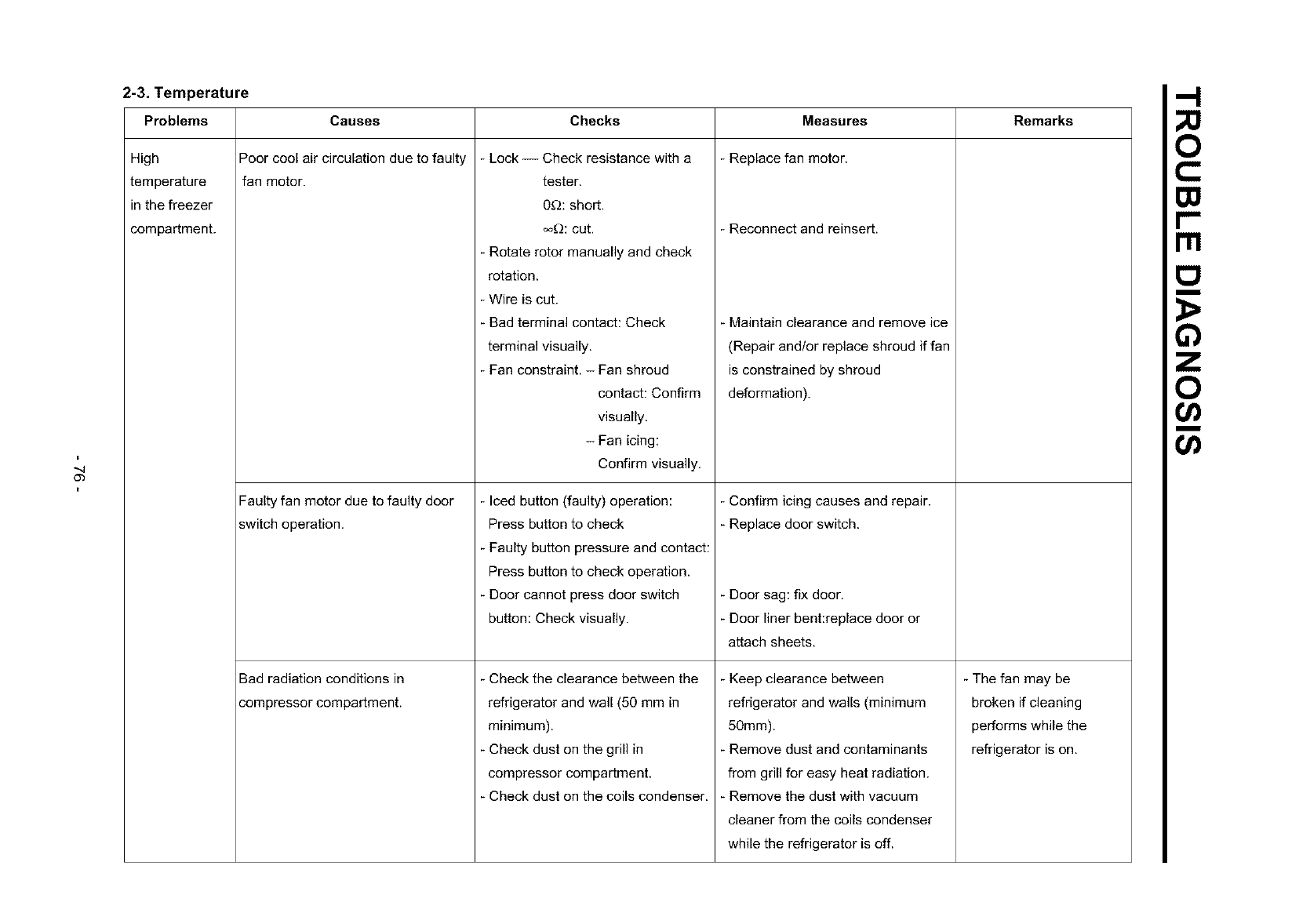
"-4
O3
2-3. Temperature
Problems
High
temperature
in the freezer
compartment.
Causes
Poor cool air circulation due to faulty
fan motor.
Faulty fan motor due to faulty door
switch operation.
Bad radiation conditions in
compressor compartment.
Checks Remarks
Lock -- Check resistance with a
tester.
0_): short.
oo_):cut.
- Rotate rotor manually and check
rotation.
- Wire is cut.
- Bad terminal contact: Check
terminal visually.
- Fan constraint. - Fan shroud
contact: Confirm
visually.
- Fan icing:
Confirm visually.
- Iced button (faulty) operation:
Press button to check
Faulty button pressure and contact:
Press button to check operation.
- Door cannot press door switch
button: Check visually.
Check the clearance between the
refrigerator and wall (50 mm in
minimum).
- Check dust on the grill in
compressor compartment.
- Check dust on the coils condenser.
Measures
Replace fan motor.
Reconnect and reinsert.
Maintain clearance and remove ice
(Repair and/or replace shroud if fan
is constrained by shroud
deformation).
- Confirm icing causes and repair.
Replace door switch.
- Door sag: fix door.
Door liner bent:replace door or
attach sheets.
Keep clearance between
refrigerator and walls (minimum
50mm).
Remove dust and contaminants
from grill for easy heat radiation.
Remove the dust with vacuum
cleaner from the coils condenser
while the refrigerator is off.
- The fan may be
broken if cleaning
performs while the
refrigerator is on.
m
m
o
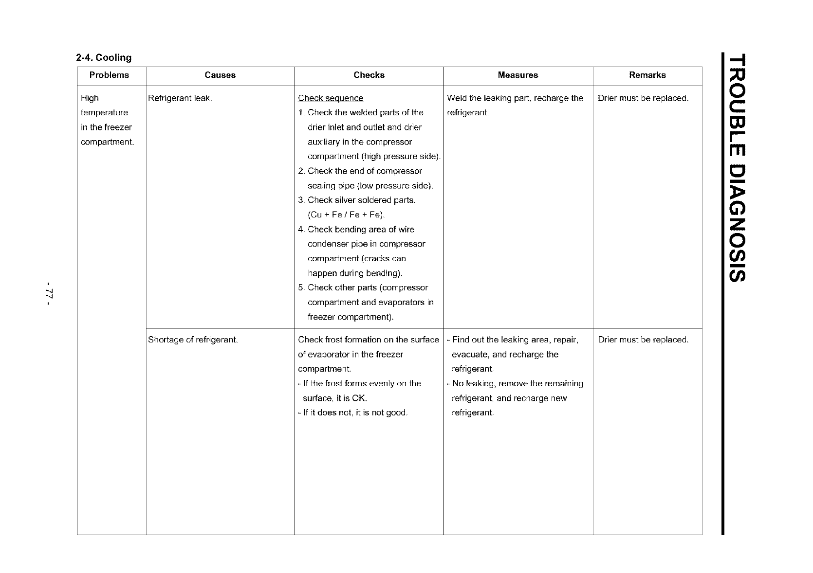
-..q
-..q
2-4. Cooling
Problems
High
temperature
in the freezer
compartment.
Causes
Refrigerant leak.
Shortage of refrigerant.
Checks
Check sequence
1. Check the welded parts of the
drier inlet and outlet and drier
auxiliary in the compressor
compartment (high pressure side).
2. Check the end of compressor
sealing pipe (low pressure side).
3. Check silver soldered parts.
(Cu + Fe IFe + Fe).
4. Check bending area of wire
condenser pipe in compressor
compartment (cracks can
happen during bending).
5. Check other parts (compressor
compartment and evaporators in
freezer compartment).
Check frost formation on the surface
of evaporator in the freezer
compartment.
- If the frost forms evenly on the
surface, it is OK.
If it does not, it is not good.
Measures
Weld the leaking part, recharge the
refrigerant.
Find out the leaking area, repair,
evacuate, and recharge the
refrigerant.
No leaking, remove the remaining
refrigerant, and recharge new
refrigerant.
Remarks
Drier must be replaced.
Drier must be replaced.
Ill
m
o
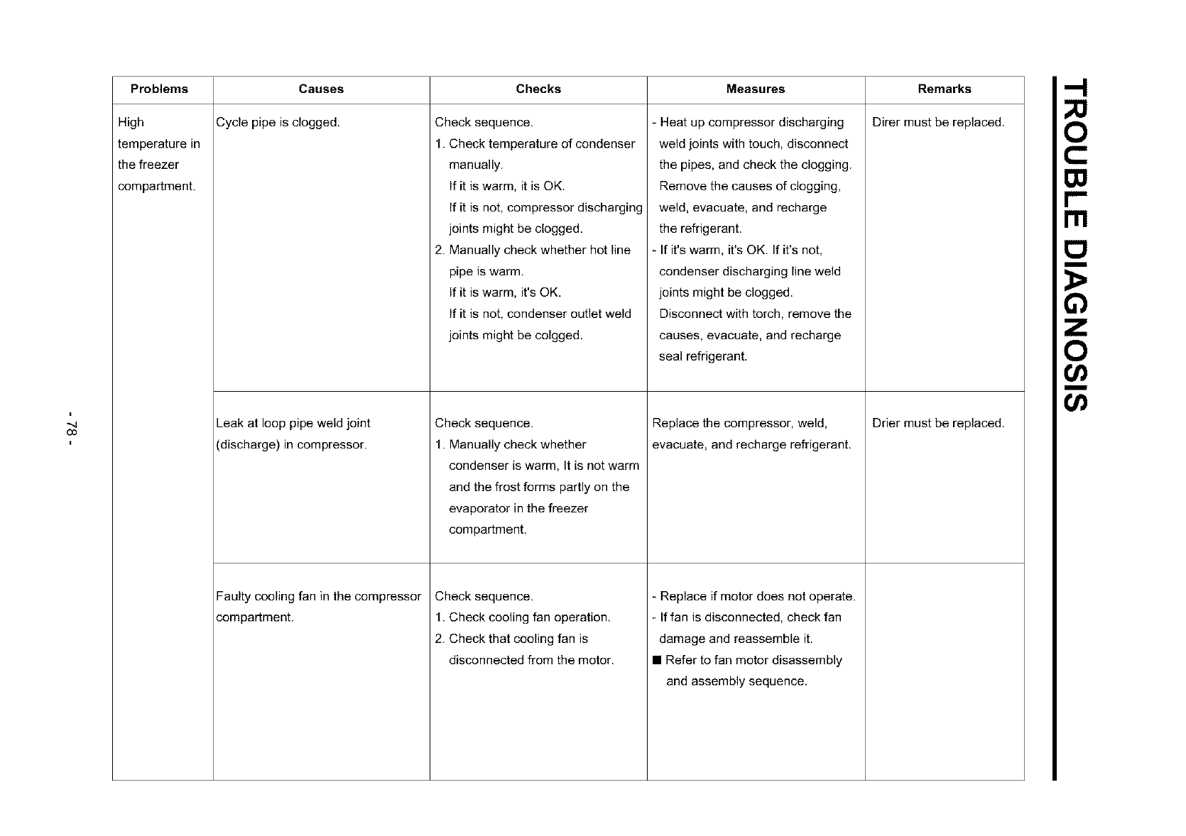
"4
O3
Problems Checks Measures
High
temperature in
the freezer
compartment.
Causes
Cycle pipe is clogged.
Leak at loop pipe weld joint
(discharge) in compressor.
Faulty cooling fan in the compressor
compartment.
Check sequence.
1. Check temperature of condenser
manually.
If it is warm, it is OK.
If it is not, compressor discharging
joints might be clogged.
2. Manually check whether hot line
pipe is warm.
If it is warm, it's OK.
If it is not, condenser outlet weld
joints might be colgged.
Check sequence.
1. Manually check whether
condenser is warm, It is not warm
and the frost forms partly on the
evaporator in the freezer
compartment.
Check sequence.
1. Check cooling fan operation.
2. Check that cooling fan is
disconnected from the motor.
- Heat up compressor discharging
weld joints with touch, disconnect
the pipes, and check the clogging.
Remove the causes of clogging,
weld, evacuate, and recharge
the refrigerant.
- If it's warm, it's OK. If it's not,
condenser discharging line weld
joints might be clogged.
Disconnect with torch, remove the
causes, evacuate, and recharge
seal refrigerant.
Replace the compressor, weld,
evacuate, and recharge refrigerant.
- Replace if motor does not operate.
- If fan is disconnected, check fan
damage and reassemble it.
• Refer to fan motor disassembly
and assembly sequence.
Remarks
Direr must be replaced.
Drier must be replaced.
rrl
m
o
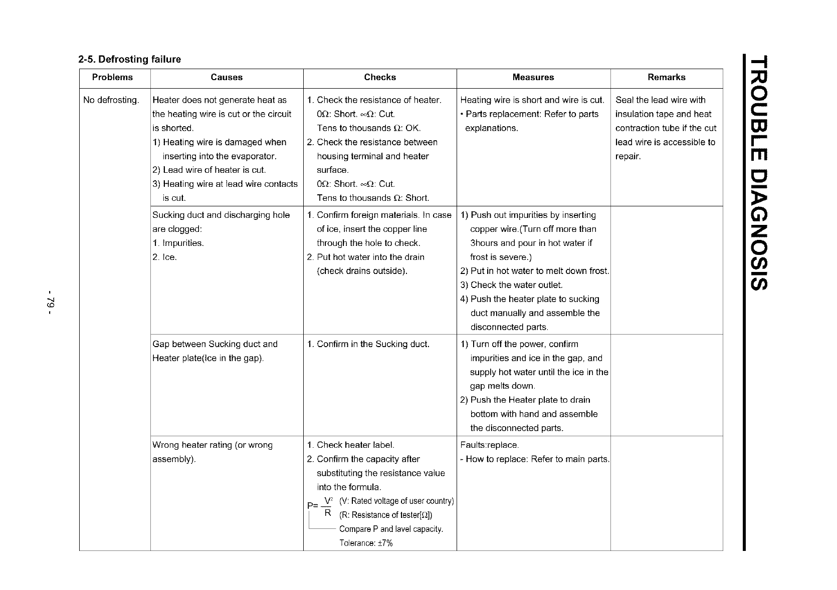
-..q
¢O
2-5. Defrosting failure
Problems Causes
No defrosting. Heater does not generate heat as
the heating wire is cut or the circuit
is shorted.
1) Heating wire is damaged when
inserting into the evaporator.
2) Lead wire of heater is cut.
3) Heating wire at lead wire contacts
is cut.
Sucking duct and discharging hole
are clogged:
1. Impurities.
2. Ice.
Gap between Sucking duct and
Heater plate(Ice in the gap).
Wrong heater rating (or wrong
assembly).
Checks Measures Remarks
1. Check the resistance of heater.
0D: Short. o_): Cut.
Tens to thousands D: OK.
2. Check the resistance between
housing terminal and heater
surface.
0_: Short. o_: Cut.
Tens to thousands _: Short.
1. Confirm foreign materials. In case
of ice, insert the copper line
through the hole to check.
2. Put hot water into the drain
(check drains outside).
1. Confirm in the Sucking duct.
1. Check heater label.
2. Confirm the capacity after
substituting the resistance value
into the formula.
V2 (V: Ratedvoltage0f user country)
p=--
R (R: Resistanceof tester[D])
CompareP and lave1capacity.
Tolerance:+7%
Heating wire is short and wire is cut.
•Parts replacement: Refer to parts
explanations.
1) Push out impurities by inserting
copper wire.(Turn off more than
3hours and pour in hot water if
frost is severe.)
2) Put in hot water to melt down frost.
3) Check the water outlet.
4) Push the heater plate to sucking
duct manually and assemble the
disconnected parts.
1) Turn off the power, confirm
impurities and ice in the gap, and
supply hot water until the ice in the
gap melts down.
2) Push the Heater plate to drain
bottom with hand and assemble
the disconnected parts.
Faults:replace.
-How to replace: Refer to main parts.
Seal the lead wire with
insulation tape and heat
contraction tube if the cut
lead wire is accessible to
repair.
m
Ill
m
o
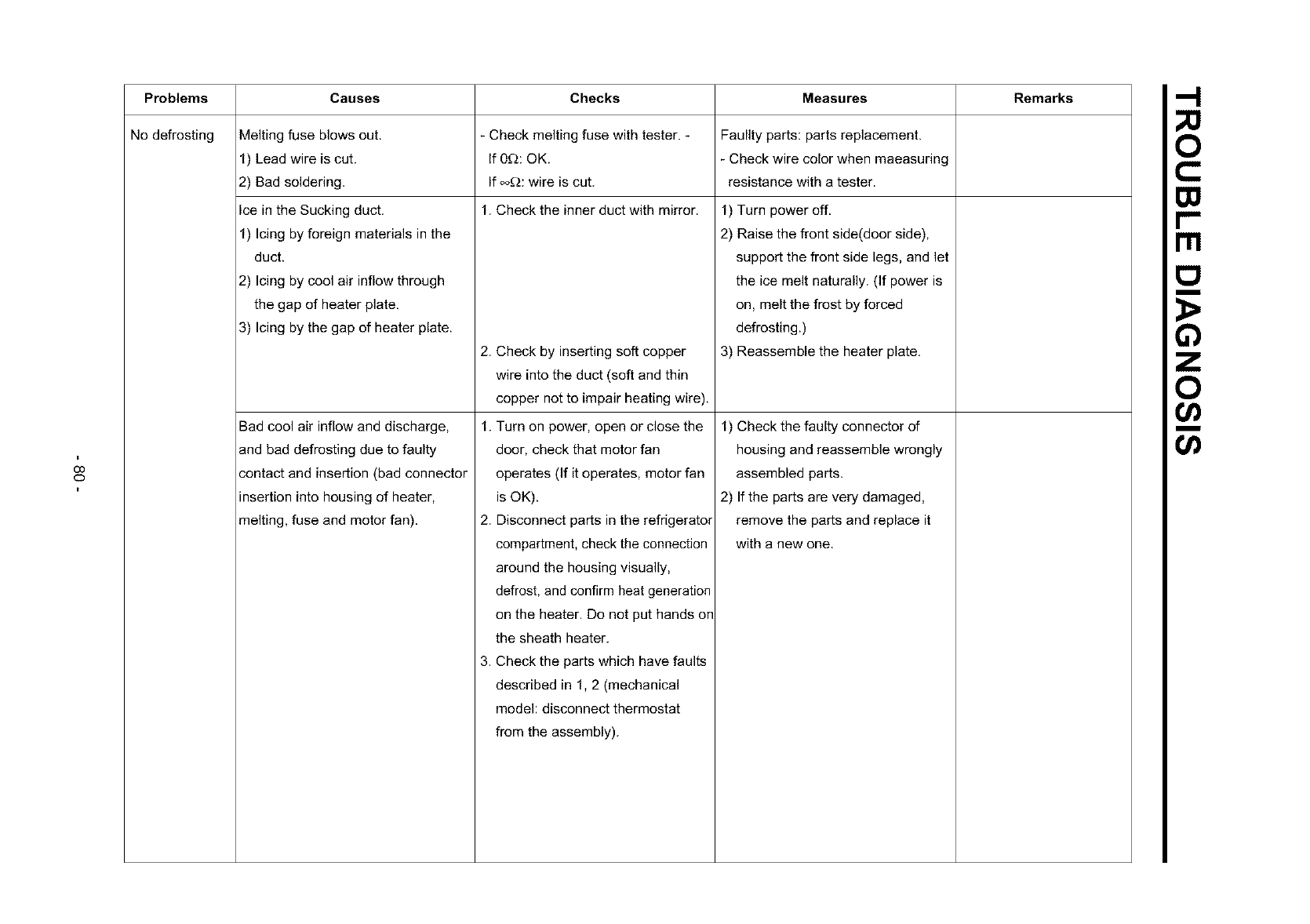
OO
O
Problems Causes Checks Measures Remarks
No defrosting Melting fuse blows out. _ Check melting fuse with tester. - Faullty parts: parts replacement.
1) Lead wire is cut. If 0£_: OK. - Check wire color when maeasuring
2) Bad soldering. If _: wire is cut. resistance with a tester.
Ice in the Sucking duct. 1. Check the inner duct with mirror. 1) Turn power off.
1) Icing by foreign materials in the
duct.
2) Icing by cool air inflow through
the gap of heater plate.
3) Icing by the gap of heater plate.
2) Raise the front side(door side),
support the front side legs, and let
the ice melt naturally. (If power is
on, melt the frost by forced
defrosting.)
Bad cool air inflow and discharge,
and bad defrosting due to faulty
contact and insertion (bad connector
insertion into housing of heater,
melting, fuse and motor fan).
2. Check by inserting soft copper
wire into the duct (soft and thin
copper not to impair heating wire).
1. Turn on power, open or close the
door, check that motor fan
operates (If it operates, motor fan
is OK).
2. Disconnect parts in the refrigerator
compartment, check the connection
around the housing visually,
defrost, and confirm heat generation
on the heater. Do not put hands on
the sheath heater.
3. Check the parts which have faults
described in 1, 2 (mechanical
model: disconnect thermostat
from the assembly).
3) Reassemble the heater plate.
1) Check the faulty connector of
housing and reassemble wrongly
assembled parts.
2) If the parts are very damaged,
remove the parts and replace it
with a new one.
rrl
m
o
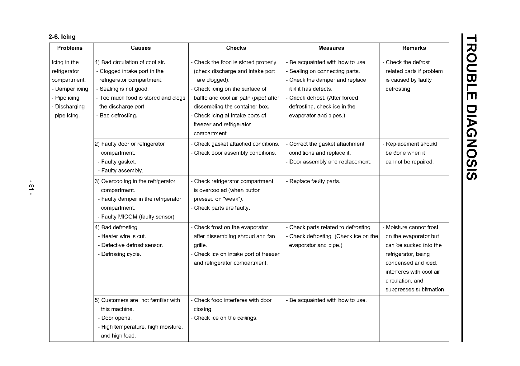
O3
2-6. Icing
Problems
Icing in the
refrigerator
compartment.
- Damper icing.
- Pipe icing.
- Discharging
pipe icing.
Causes Checks Measures Remarks
1) Bad circulation of cool air.
- Clogged intake port in the
refrigerator compartment.
- Sealing is not good.
- Toe much food is stored and clogs
the discharge port.
- Bad defrosting.
2) Faulty door or refrigerator
compartment.
- Faulty gasket.
- Faulty assembly.
3) Overcooling in the refrigerator
compartment.
- Faulty damper in the refrigerator
compartment.
- Faulty MICOM (faulty sensor)
4) Bad defrosting
- Heater wire is cut.
- Defective defrost sensor.
- Defresing cycle.
5) Customers are not familiar with
this machine.
Door opens.
High temperature, high moisture,
and high load.
Check the food is stored properly
(check discharge and intake port
are clogged).
Check icing on the surface of
baffle and cool air path (pipe) after
dissembling the container box.
Check icing at intake ports of
freezer and refrigerator
compartment.
Check gasket attached conditions.
Check door assembly conditions.
Check refrigerator compartment
is overcooled (when button
pressed on "weak").
- Check parts are faulty.
Check frost on the evaporator
after dissembling shroud and fan
grille.
Check ice on intake port of freezer
and refrigerator compartment.
Check food interferes with door
closing.
Check ice on the ceilings.
- Be acquainted with how to use.
- Sealing on connecting parts.
- Check the damper and replace
it if it has defects.
- Check defrost. (After forced
defrosting, check ice in the
evaporator and pipes.)
- Correct the gasket attachment
conditions and replace it.
- Door assembly and replacement.
- Replace faulty parts.
Check parts related to defrosting.
- Check defrosting, (Check ice on the
evaporator and pipe.)
Be acquainted with how to use.
Check the defrost
related parts if problem
is caused by faulty
defrosting.
Replacement should
be done when it
cannot be repaired.
- Moisture cannot frost
on the evaporator but
can be sucked into the
refrigerator, being
condensed and iced,
interferes with cool air
circulation, and
suppresses sublimation.
Ill
I:1
m
o
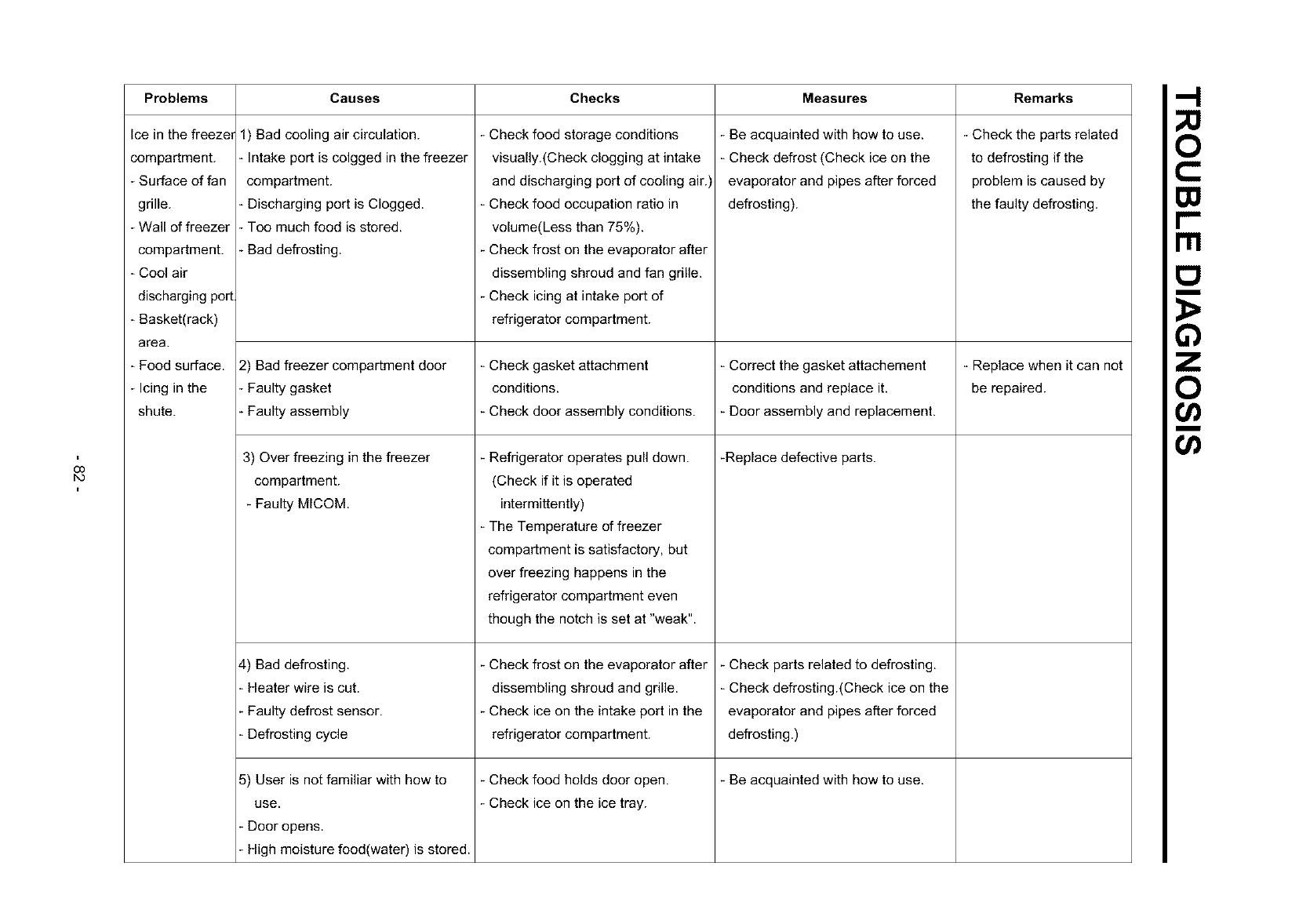
O0
bO
Problems Causes Checks Measures Remarks
Ice in the freezer
compartment.
- Surface of fan
grille.
- Wall of freezer
compartment.
- Cool air
discharging port
- Basket(rack)
area.
- Food surface.
- Icing in the
shute.
1) Bad cooling air circulation.
Intake port is colgged in the freezer
compartment.
- Discharging port is Clogged.
- Too much food is stored.
- Bad defrosting.
2) Bad freezer compartment door
-Faulty gasket
- Faulty assembly
- Check food storage conditions
visually.(Check clogging at intake
and discharging port of cooling air.)
- Check food occupation ratio in
volume(Less than 75%).
- Check frost on the evaporator after
dissembling shroud and fan grille.
- Check icing at intake port of
refrigerator compartment.
3) Over freezing in the freezer
compartment.
- Faulty MICOM.
4) Bad defrosting.
Heater wire is cut.
Faulty defrost sensor.
Defrosting cycle
5) User is not familiar with how to
use.
Door opens.
High moisture food(water) is stored.
- Check gasket attachment
conditions.
- Check door assembly conditions.
- Refrigerator operates pull down.
(Check if it is operated
intermittently)
- The Temperature of freezer
compartment is satisfactory, but
over freezing happens in the
refrigerator compartment even
though the notch is set at "weak".
- Check frost on the evaporator after
dissembling shroud and grille.
- Check ice on the intake port in the
refrigerator compartment.
- Check food holds door open.
- Check ice on the ice tray.
- Be acquainted with how to use.
- Check defrost (Check ice on the
evaporator and pipes after forced
defrosting).
- Correct the gasket attachement
conditions and replace it.
- Door assembly and replacement.
-Replace defective parts.
- Check parts related to defrosting.
- Check defrosting.(Check ice on the
evaporator and pipes after forced
defrosting.)
- Be acquainted with how to use.
- Check the parts related
to defrosting if the
problem is caused by
the faulty defrosting.
- Replace when it can not
be repaired.
rrl
m
o
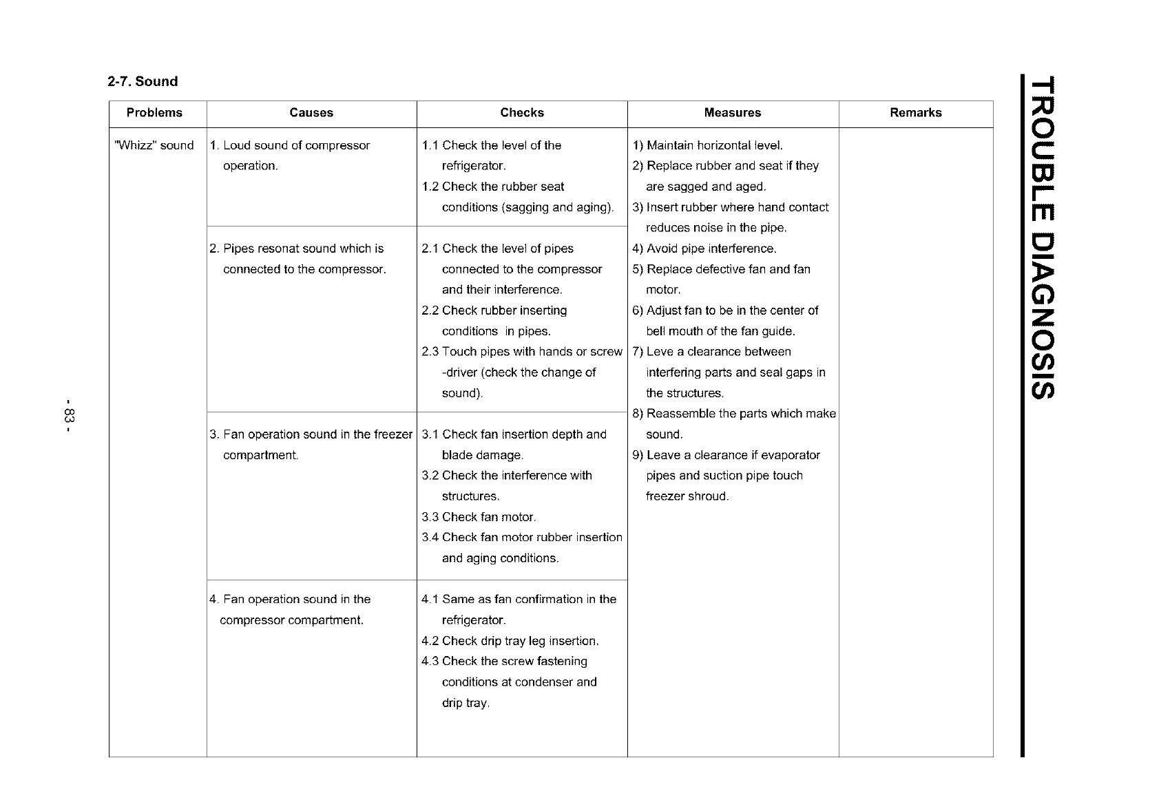
O0
CO
2-7. Sound
Problems
"Whizz" sound
Causes
1. Loud sound of compressor
operation.
2. Pipes resonat sound which is
connected to the compressor.
3. Fan operation sound in the freezer
compartment.
4. Fan operation sound in the
compressor compartment.
Checks Measures Remarks
1.1 Check the level of the
refrigerator.
1.2 Check the rubber seat
conditions (sagging and aging).
2.1 Check the level of pipes
connected to the compressor
and their interference.
2.2 Check rubber inserting
conditions in pipes.
2.3 Touch pipes with hands or screw
-driver (check the change of
sound).
3.1 Check fan insertion depth and
blade damage.
3.2 Check the interference with
structures.
3.3 Check fan motor.
3.4 Check fan motor rubber insertion
and aging conditions.
4.1 Same as fan confirmation in the
refrigerator.
4.2 Check drip tray leg insertion.
4.3 Check the screw fastening
conditions at condenser and
drip tray.
1) Maintain horizontal level.
2) Replace rubber and seat if they
are sagged and aged.
3) Insert rubber where hand contact
reduces noise in the pipe.
4) Avoid pipe interference.
5) Replace defective fan and fan
motor.
6) Adjust fan to be in the center of
bell mouth of the fan guide.
7) Leve a clearance between
interfering parts and seal gaps in
the structures.
8) Reassemble the parts which make
sound.
9) Leave a clearance if evaporator
pipes and suction pipe touch
freezer shroud.
rrl
m
o
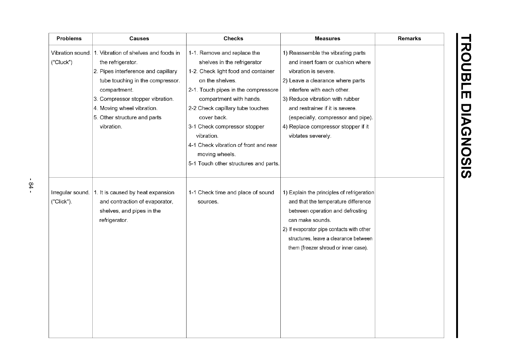
O3
4_
Problems
Vibration sound.
("Cluck")
Irregular sound.
("Click").
Causes Checks Measures Remarks
1-1. Remove and replace the
shelves in the refrigerator
1-2. Check light food and container
on the shelves.
2-1. Touch pipes in the compressere
compartment with hands.
2-2 Check capillary tube touches
cover back.
3-1 Check compressor stopper
vibration.
4-1 Check vibration of front and rear
moving wheels,
5-1 Touch other structures and parts.
1. Vibration of shelves and foods in
the refrigerator.
2. Pipes interference and capillary
tube touching in the compressor.
compartment.
3. Compressor stopper vibration.
4. Moving wheel vibration.
5. Other structure and parts
vibration.
1. It is caused by heat expansion
and contraction of evaporator,
shelves, and pipes in the
refrigerator.
1-1 Check time and place of sound
sources.
1) Reassemble the vibrating parts
and insert foam or cushion where
vibration is severe.
2) Leave a clearance where parts
interfere with each other.
3) Reduce vibration with rubber
and restrainer if it is severe.
(especially, compressor and pipe).
4) Replace compressor stopper if it
vibtates severely.
1) Explain the principles of refrigeration
and that the temperature difference
between operation and defrosting
can make sounds.
2) If evaporator pipe contacts with other
structures, leave a clearance between
them (freezer shroud or inner case),
Ill
m
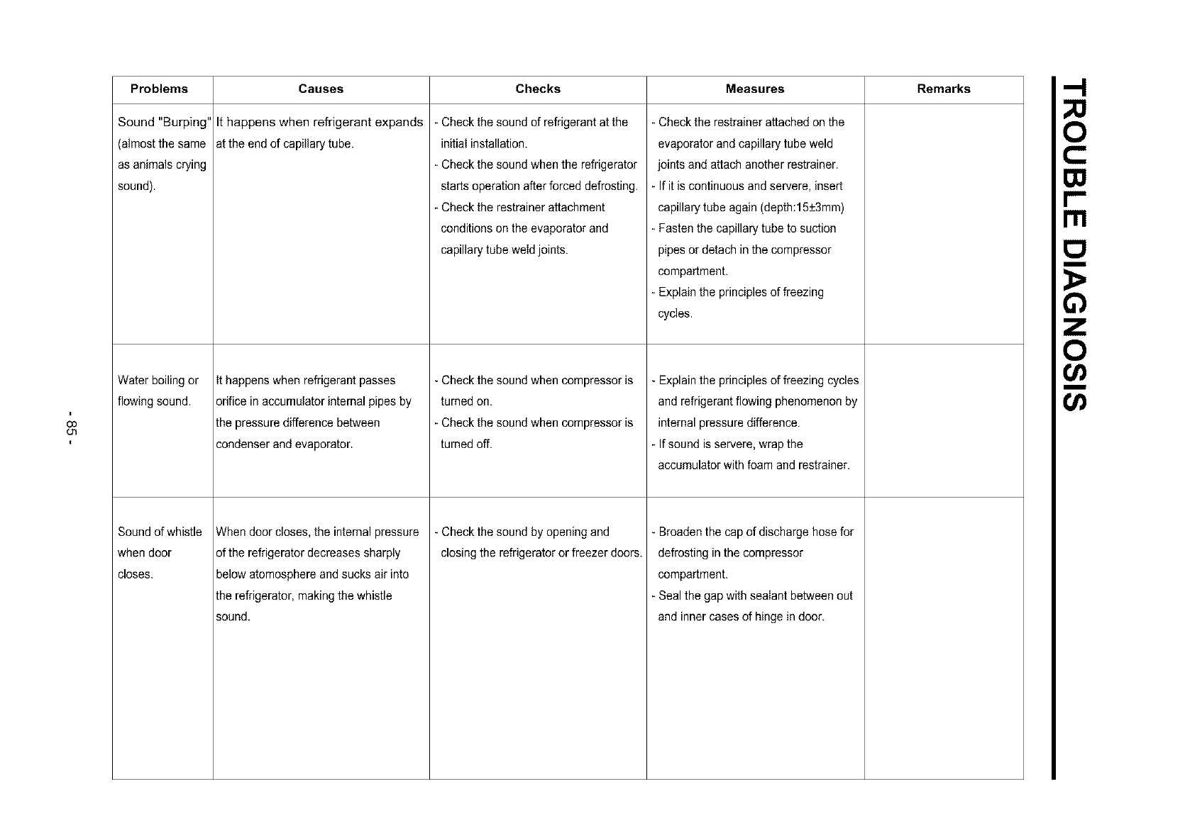
O0
Ol
Problems Checks Measures Remarks
Sound "Burping"
(almostthe same
as animals crying
sound).
Water boiling or
flowing sound.
Sound of whistle
when door
closes.
Causes
It happens when refrigerant expands
at the end of capillary tube.
It happens when refrigerant passes
orifice inaccumulator internal pipes by
the pressure difference between
condenser and evaporator.
When door closes, the internal pressure
of the refrigerator decreases sharply
below atomosphere and sucks air into
lhe refrigerator, makingthe whistle
sound.
- Check the sound of refrigerant at the
initial installation.
- Check the sound when the refrigerator
starts operation after forced defrosting.
- Check the restrainer attachment
conditions on the evaporator and
capillary tube weld joints.
- Checkthe sound when compressoris
turned on.
- Checkthe sound when compressoris
turned off.
- Check the sound by opening and
closing the refrigerator or freezer doors.
- Check the restrainer attached on the
evaporator and capillary tube weld
joints and attach another restrainer.
- If it is continuous and servere, insert
capillary tube again (depth:15+3mm)
- Fasten the capillary tube to suction
pipes or detach in the compressor
compartment.
- Explain the principles of freezing
cycles.
- Explain the principles of freezing cycles
and refrigerant flowing phenomenon by
internal pressure difference.
- If sound is servere, wrap the
accumulator with foam and restrainer.
- Broaden the cap of discharge hose for
defrosting in the compressor
compartment.
- Seal the gap with sealant between out
and inner cases of hinge in door.
rrl
m
o
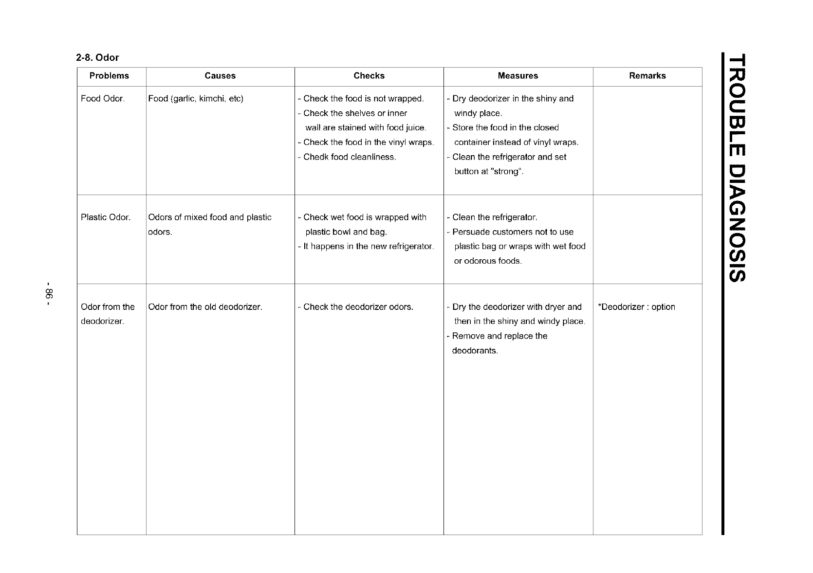
O0
O3
2-8. Odor
Problems
Food Odor.
Plastic Odor.
Odor from the
deodorizer.
Causes
Food (garlic, kimchi, etc)
Odors of mixed food and plastic
odors.
Odor from the old deodorizer.
Checks Measures Remarks
Check the food is not wrapped.
Check the shelves or inner
wall are stained with food juice.
Check the food in the vinyl wraps.
- Chedk food cleanliness.
Check wet food is wrapped with
plastic bowl and bag.
It happens in the new refrigerator.
- Check the deodorizer odors.
Dry deodorizer in the shiny and
windy place.
Store the food in the closed
container instead of vinyl wraps.
Clean the refrigerator and set
button at "strong".
Clean the refrigerator.
Persuade customers not to use
plastic bag or wraps with wet food
or odorous foods.
- Dry the deodorizer with dryer and
then in the shiny and windy place.
- Remove and replace the
deodorants.
*Deodorizer : option
rrl
m
o
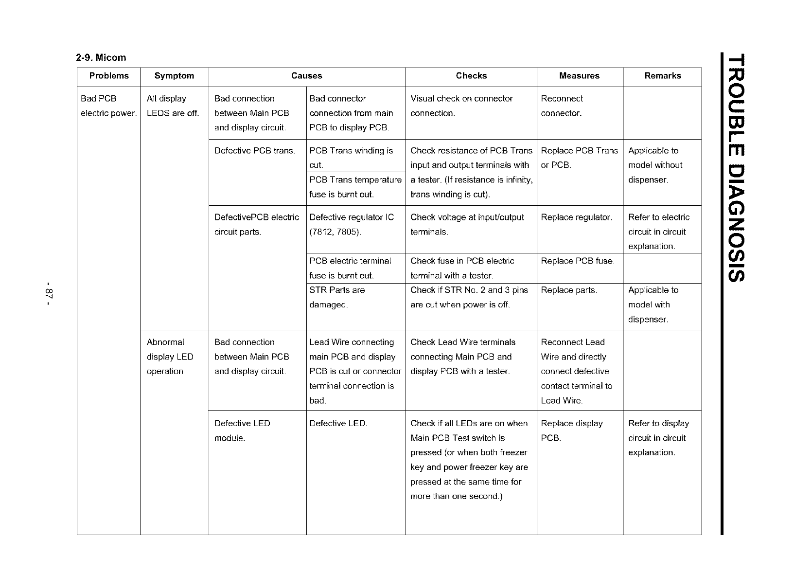
O0
*-4
2-9. Micom
Problems Symptom Causes Checks Measures Remarks
Bad PCB All display Bad connection Bad connector Visual check on connector Reconnect
electric power. LEDS are off. between Main PCB connection from main connection, connector.
and display circuit. PCB to display PCB.
Defective PCB trans.
Abnormal
display LED
operation
PCB Trans winding is
cut.
PCB Trans temperature
fuse is burnt out.
Check resistance of PCB Trans
input and output terminals with
a tester. (If resistance is infinity,
trans winding is cut).
Replace PCB Trans
or PCB.
Applicable to
model without
dispenser.
DefectivePCB electric Defective regulator IC Check voltage at input/output Replace regulator. Refer to electric
circuit parts. (7812, 7805). terminals, circuit in circuit
explanation.
PCB electric terminal Check fuse in PCB electric Replace PCB fuse.
fuse is burnt out. terminal with a tester.
STR Parts are Check if STR No. 2 and 3 pins Replace parts. Applicable to
damaged, are cut when power is off. model with
dispenser.
Lead Wire connecting
main PCB and display
PCB is cut or connector
terminal connection is
bad.
Bad connection
between Main PCB
and display circuit.
Check Lead Wire terminals
connecting Main PCB and
display PCB with a tester.
Check if all LEDs are on when
Main PCB Test switch is
pressed (or when both freezer
key and power freezer key are
pressed at the same time for
more than one second.)
Defective LED
module.
Reconnect Lead
Wire and directly
connect defective
contact terminal to
Lead Wire.
Replace display
PCB.
Defective LED. Refer to display
circuit in circuit
explanation.
Ill
m
o
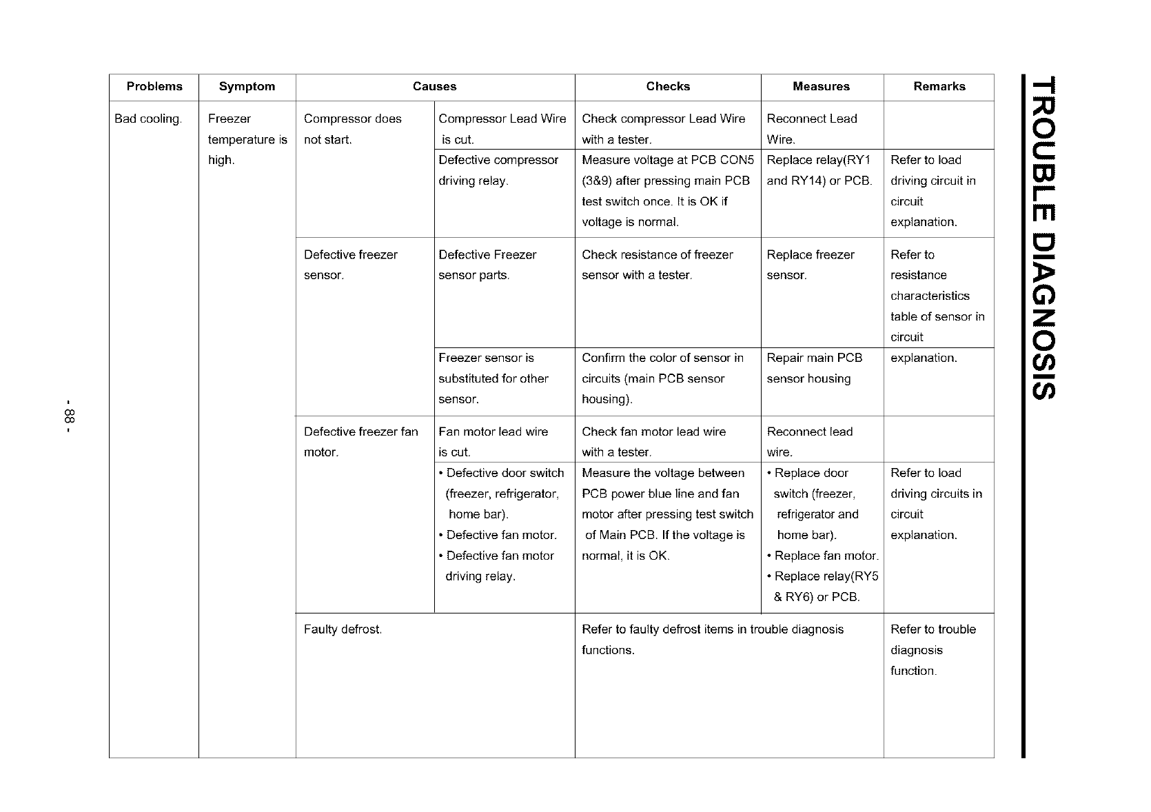
O0
O0
Problems
Bad cooling,
Symptom
Freezer
temperature is
high.
Compressor does
not start.
Defective freezer
sensor.
Causes Checks Measures Remarks
Compressor Lead Wire
is cut.
Defective compressor
driving relay.
Defective Freezer
sensor parts.
Check compressor Lead Wire
with a tester.
Measure voltage at PCB CON5
(3&9) after pressing main PCB
test switch once. It is OK if
voltage is normal.
Check resistance of freezer
sensor with a tester.
Reconnect Lead
Wire.
Replace relay(RY1
and RY14) or PCB.
Replace freezer
sensor.
Freezer sensor is Confirm the color of sensor in Repair main PCB
substituted for other circuits (main PCB sensor sensor housing
sensor, housing).
Defective freezer fan
motor.
Check fan motor lead wire
with a tester.
Measure the voltage between
PCB power blue line and fan
motor after pressing test switch
of Main PCB. If the voltage is
normal, it is OK.
Faulty defrost.
Fan motor lead wire
is cut.
• Defective door switch
(freezer, refrigerator,
home bar).
• Defective fan motor.
• Defective fan motor
driving relay.
Reconnect lead
wire.
• Replace door
switch (freezer,
refrigerator and
home bar).
• Replace fan motor.
• Replace relay(RY5
& RY6) or PCB.
Refer to faulty defrost items in trouble diagnosis
functions.
Refer to load
driving circuit in
circuit
explanation.
Refer to
resistance
characteristics
table of sensor in
circuit
explanation.
Refer to load
driving circuits in
circuit
explanation.
Refer to trouble
diagnosis
function.
Ill
m
o
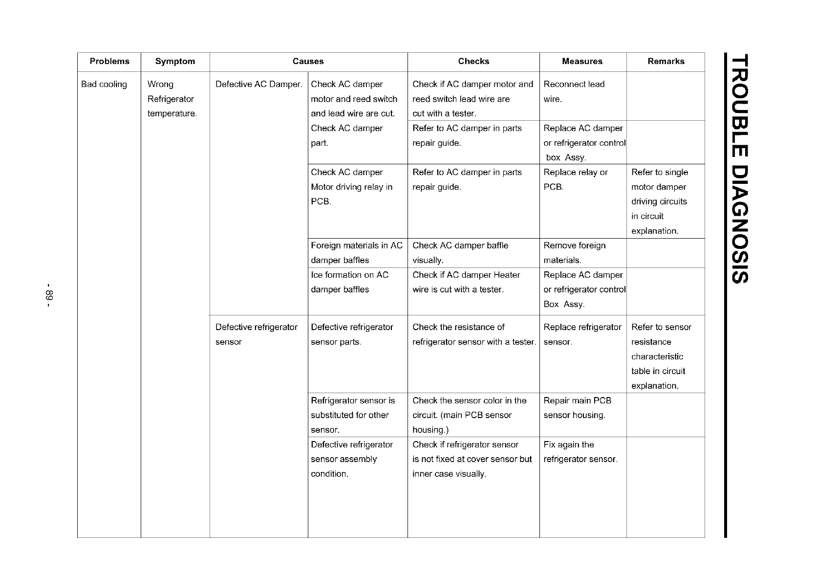
O0
¢O
Problems
Bad cooling
Symptom Checks Remarks
Wrong
Refrigerator
temperature.
Causes
Defective AC Damper.
Defective refrigerator
sensor
Check AC damper
motor and reed switch
and lead wire are cut.
Check AC damper
3art.
Check if AC damper motor and
reed switch lead wire are
cut with a tester.
Refer to AC damper in parts
repair guide.
Measures
Reconnect lead
wire.
Replace AC damper
or refrigerator control
box Assy.
Check AC damper Refer to AC damper in parts Replace relay or Refer to single
Motor driving relay in repair guide. PCB. motor damper
PCB. driving circuits
in circuit
explanation.
Foreign materials in AC Check AC damper baffle
damper baffles visually.
Ice formation on AC Check if AC damper Heater
damper baffles wire is cut with a tester.
Defective refrigerator
sensor parts.
Check the resistance of
refrigerator sensor with a tester.
Check the sensor color in the
circuit. (main PCB sensor
housing.)
Check if refrigerator sensor
is not fixed at cover sensor but
inner case visually.
Refrigerator sensor is
substituted for other
sensor.
Defective refrigerator
sensor assembly
condition.
Remove foreign
materials.
Replace AC damper
or refrigerator control
Box Assy.
Replace refrigerator
sensor,
Repair main PCB
sensor housing.
Fix again the
refrigerator sensor.
Refer to sensor
resistance
characteristic
table in circuit
explanation.
O0
rrl
m
o
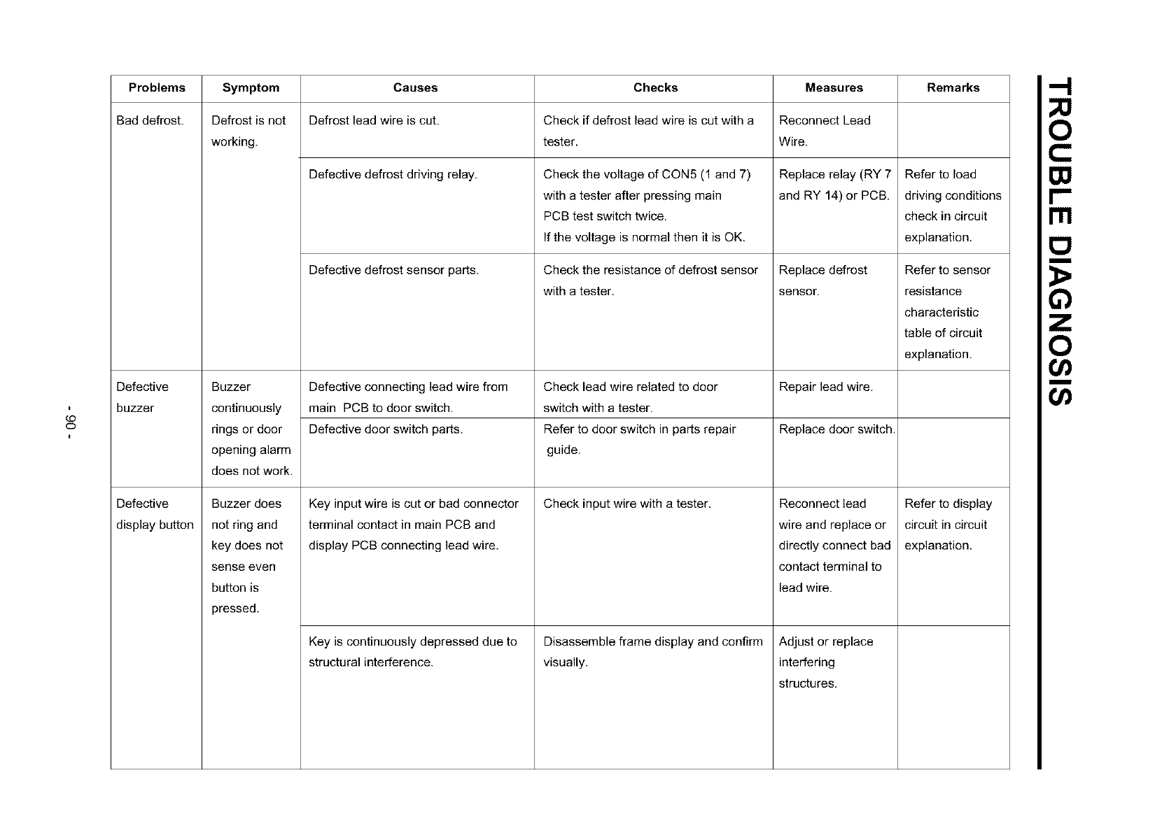
¢O
O
Problems Symptom Causes Checks Measures Remarks
Bad defrost. Defrost is not Defrost lead wire is cut. Check if defrost lead wire is cut with a Reconnect Lead
working, tester. Wire.
Defective defrost driving relay. Check the voltage of CON5 (1 and 7) Replace relay (RY 7 Refer to load
with a tester after pressing main and RY 14) or PCB. driving conditions
PCB test switch twice, check in circuit
If the voltage is normal then it is OK. explanation.
Defective defrost sensor parts. Check the resistance of defrost sensor
with a tester.
Defective
display button
Replace defrost
sensor.
Defective Buzzer Defective connecting lead wire from Check lead wire related to door Repair lead wire.
buzzer continuously main PCB to door switch, switch with a tester.
rings or door Defective door switch parts. Refer to door switch in parts repair Replace door switch.
opening alarm guide.
does not work.
Check input wire with a tester.Key input wire is cut or bad connector
terminal contact in main PCB and
display PCB connecting lead wire.
Buzzer does
notring and
key does not
sense even
bu_onis
pressed.
Disassemble frame display and confirm
visually.
Key is continuously depressed due to
structural interference.
Reconnect lead
wire and replace or
directly connect bad
contact terminal to
lead wire.
Adjust or replace
interfering
structures.
Refer to sensor
resistance
characteristic
table of circuit
explanation.
Refer to display
circuit in circuit
explanation.
rrl
m
o
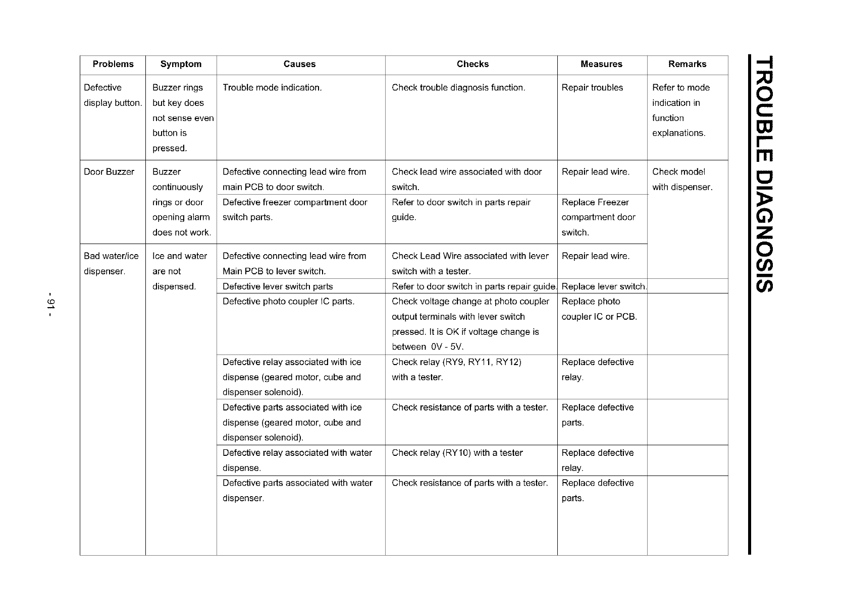
t
¢O
Problems
Defective
display button.
Door Buzzer
Symptom Remarks
Buzzer rings
but key does
not sense even
button is
pressed.
Buzzer
continuously
rings or door
opening alarm
does not work.
Causes
Trouble mode indication.
Defective connecting lead wire from
main PCB to door switch.
Defective freezer compartment door
switch parts.
Checks
Check trouble diagnosis function.
Check lead wire associated with door
switch.
Refer to door switch in parts repair
guide.
Measures
Repair troubles
Repair lead wire.
Replace Freezer
compartment door
switch.
Bad water/ice Ice and water Defective connecting lead wire from Check Lead Wire associated with lever Repair lead wire.
dispenser, are not Main PCB to lever switch, switch with a tester.
dispensed. Defective lever switch parts Refer to door switch in parts repair guide Replace lever switch
Defective photo coupler IC parts. Check voltage change at photo coupler Replace photo
output terminals with lever switch coupler IC or PCB.
pressed. It is OK if voltage change is
between 0V- 5V.
Defective relay associated with ice Check relay (RY9, RY11, RY12) Replace defective
dispense (geared motor, cube and with a tester, relay.
dispenser solenoid).
Defective parts associated with ice Check resistance of parts with a tester. Replace defective
dispense (geared motor, cube and parts.
dispenser solenoid).
Defective relay associated with water Check relay (RY10) with a tester Replace defective
dispense, relay.
Defective parts associated with water Check resistance of parts with a tester. Replace defective
dispenser, parts.
Refer to mode
indication in
function
explanations.
Check model
with dispenser.
rrl
m
o
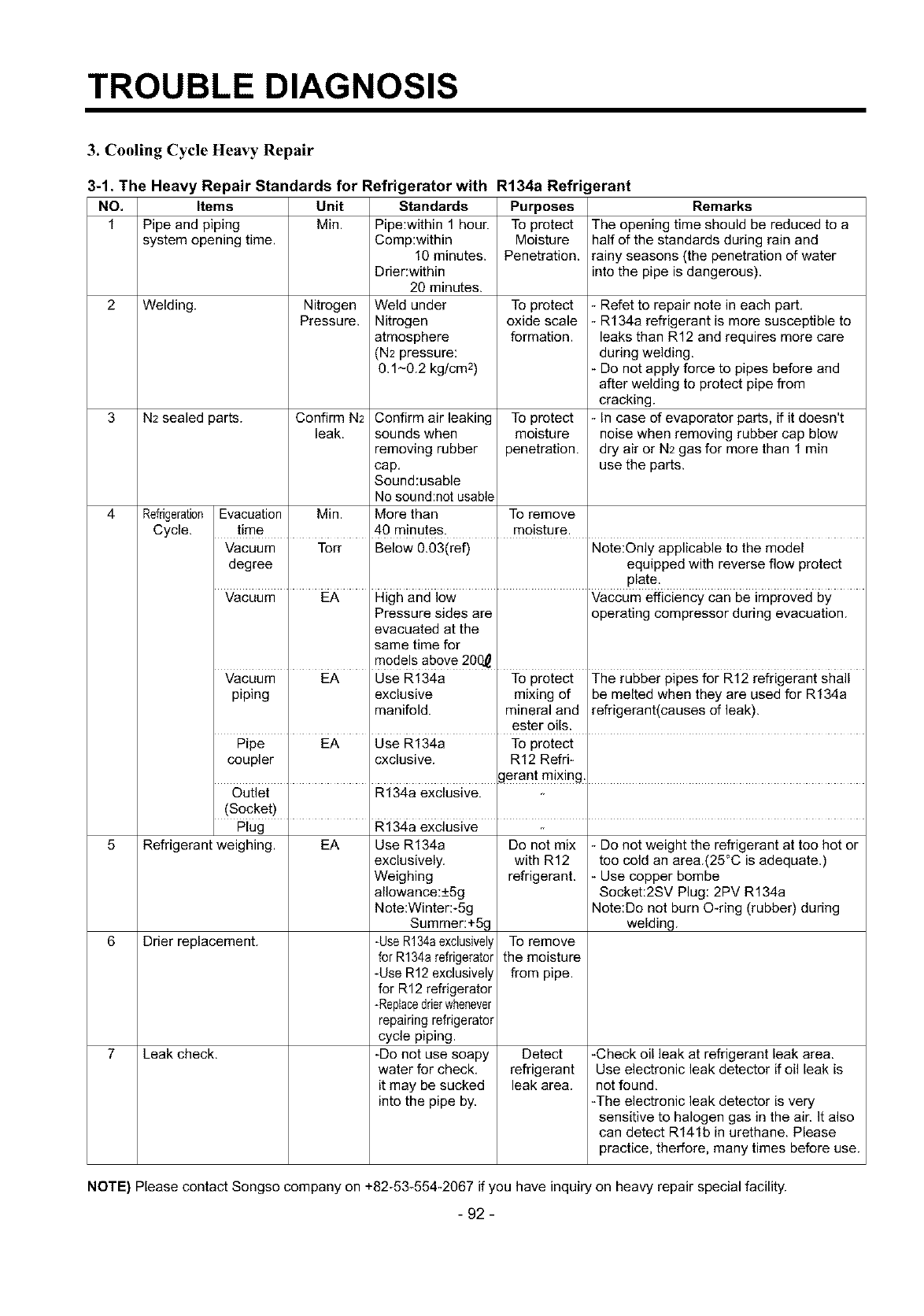
TROUBLE DIAGNOSIS
3. Cooling Cycle Heavy Repair
3-1. The Heavy Repair Standards for Refrigerator with R134a Refrigerant
NO. Items Unit Standards Purposes Remarks
1 Pipe and piping Min. Pipe:within 1 hour. To protect The opening time should be reduced to a
system opening time. Comp:within Moisture half of the standards during rain and
10minutes. Penetration. rainy seasons (the penetration of water
Drier:within into the pipe is dangerous).
20 minutes.
2 Welding. Nitrogen Weld under To protect - Refet to repair note in each part.
Pressure. Nitrogen oxide scale - R134a refrigerant is more susceptible to
atmosphere formation, leaks than R12 and requires more care
(N2 pressure: during welding.
0.1-0.2 kg/cm 2) - Do not apply force to pipes before and
after welding to protect pipe from
cracking.
3 N2 sealed parts. Confirm N2 Confirm air leaking To protect - In case of evaporator parts, if it doesn't
leak. sounds when moisture noise when removing rubber cap blow
removing rubber penetration, dry air or N2 gas for more than 1 rain
cap. use the parts.
Sound:usable
No sound:not usable
4 Refrigeration Evacuation Min. More than To remove
Cycle. time 40 minutes, moisture.
Vacuum Torr Below 0.03(ref) Note:Only applicable to the model
degree equipped with reverse flow protect
plate.
Vacuum EA High and low Vaccum efficiency can be improved by
Pressure sides are operating compressor during evacuation.
evacuated at the
same time for
models above 200_
Vacuum EA Use R134a To protect The rubber pipes for R12 refrigerant shall
piping exclusive mixing of be melted when they are used for R134a
manifold, mineral and refrigerant(causes of leak).
ester oils.
Pipe EA Use R134a To protect
coupler cxclusive. R12 Refri-
gerant mixing
Outlet R134a exclusive.
(Socket)
Plug R134a exclusive
5 Refrigerant weighing.
6 Drier replacement.
Leak check.7
EA Use R134a
exclusively.
Weighing
allowance:+5g
Note:Wintera5g
Summer:+5g
-UseR134aexclusively
for R134arefrigerator
-Use R12 exclusively
for R12 refrigerator
-Replacedrierwhenever
repairing refrigerator
cycle piping.
-Do not use soapy
water for check.
it may be sucked
into the pipe by.
Do not mix
with R12
refrigerant.
To remove
the moisture
from pipe.
Detect
refrigerant
leak area.
- Do not weight the refrigerant at too hot or
too cold an area.(25°C is adequate.)
- Use copper bombe
Socket:2SV Plug: 2PV R134a
Note:Do not burn O-ring (rubber) during
welding.
-Check oil leak at refrigerant leak area.
Use electronic leak detector if oil leak is
not found.
-The electronic leak detector is very
sensitive to halogen gas in the air. It also
can detect R141b in urethane. Please
practice, therfore, many times before use.
NOTE) Please contact Songso company on +82-53-554-2067 if you have inquiry on heavy repair special facility.
- 92 -
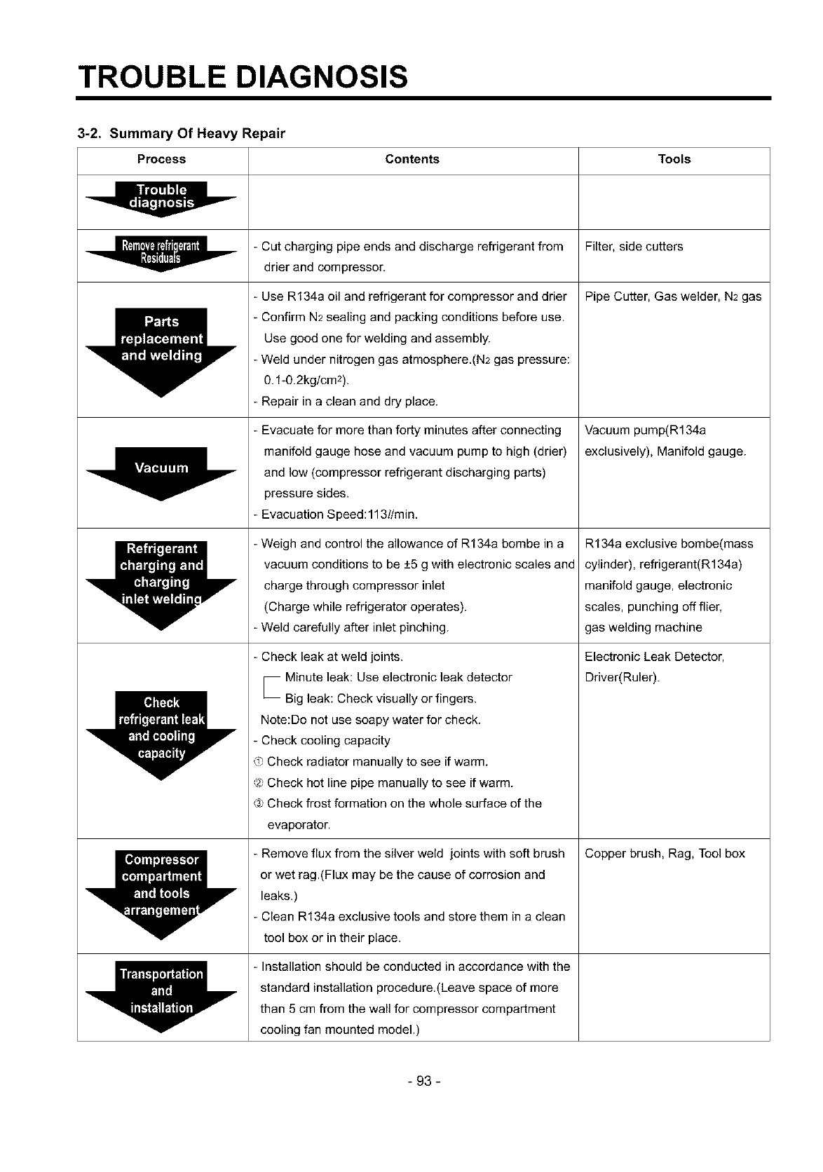
TROUBLE DIAGNOSIS
3-2. Summary Of Heavy Repair
Process Contents Tools
- Cut charging pipe ends and discharge refrigerant from Filter, side cutters
drier and compressor.
Pipe Cutter, Gas welder, N2 gas
Y
I111_1 Y
- Use R134a oil and refrigerant for compressor and drier
- Confirm N2sealing and packing conditions before use.
Use good one for welding and assembly.
- Weld under nitrogen gas atmosphere.(N2 gas pressure:
0.1-0.2kg/cm2).
- Repair in aclean and dry place.
- Evacuate for more than forty minutes after connecting
manifold gauge hose and vacuum pump to high (drier)
and low (compressor refrigerant discharging parts)
pressure sides.
- Evacuation Speed:113l/min.
- Weigh and control the allowance of R134a bombe in a
vacuum conditions to be +5 g with electronic scales and
charge through compressor inlet
(Charge while refrigerator operates).
- Weld carefully after inlet pinching.
- Check leak at weld joints.
_ Minute leak: Use electronic leak detector
Big leak: Check visually or fingers.
Note:Do not use soapy water for check.
- Check cooling capacity
0_Check radiator manually to see if warm.
_ Check hot line pipe manually to see if warm.
@Check frost formation on the whole surface of the
evaporator.
- Remove flux from the silver weld joints with soft brush
or wet rag.(Flux may be the cause of corrosion and
leaks.)
- Clean R134a exclusive tools and store them in a clean
tool box or in their place.
- Installation should be conducted in accordance with the
standard installation procedure.(Leave space of more
than 5 cm from the wall for compressor compartment
cooling fan mounted model.)
Vacuum pump(R134a
exclusively), Manifold gauge.
R134a exclusive bombe(mass
cylinder), refrigerant(R134a)
manifold gauge, electronic
scales, punching off flier,
gas welding machine
Electronic Leak Detector,
Driver(Ruler).
Copper brush, Rag, Tool box
- 93 -
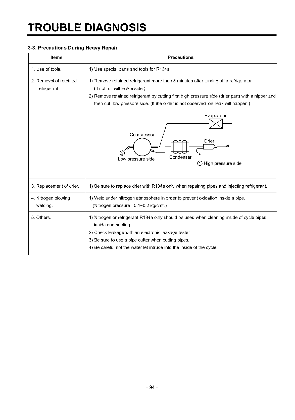
TROUBLE DIAGNOSIS
3-3. Precautions During Heavy Repair
Precautions
1) Use special parts and tools for R134a.
Items
1. Use of tools.
2. Removal of retained
refrigerant.
1) Remove retained refrigerant more than 5 minutes after turning off a refrigerator.
(If not, oil will leak inside.)
2) Remove retained refrigerant by cutting first high pressure side (drier part) with a nipper and
then cut low pressure side. (If the order is not observed, oil leak will happen.)
Evaporator
_side
3. Replacement of drier. 1) Be sure to replace drier with R134a only when repairing pipes and injecting refrigerant.
4. Nitrogen blowing 1) Weld under nitrogen atmosphere in order to prevent oxidation inside a pipe.
welding. (Nitrogen pressure : 0.1-0.2 kglcm2.)
5. Others. 1) Nitrogen or refrigerant R134a only should be used when cleaning inside of cycle pipes
inside and sealing.
2) Check leakage with an electronic leakage tester.
3) Be sure to use a pipe cutter when cutting pipes.
4) Be careful not the water let intrude into the inside of the cycle.
- 94 -
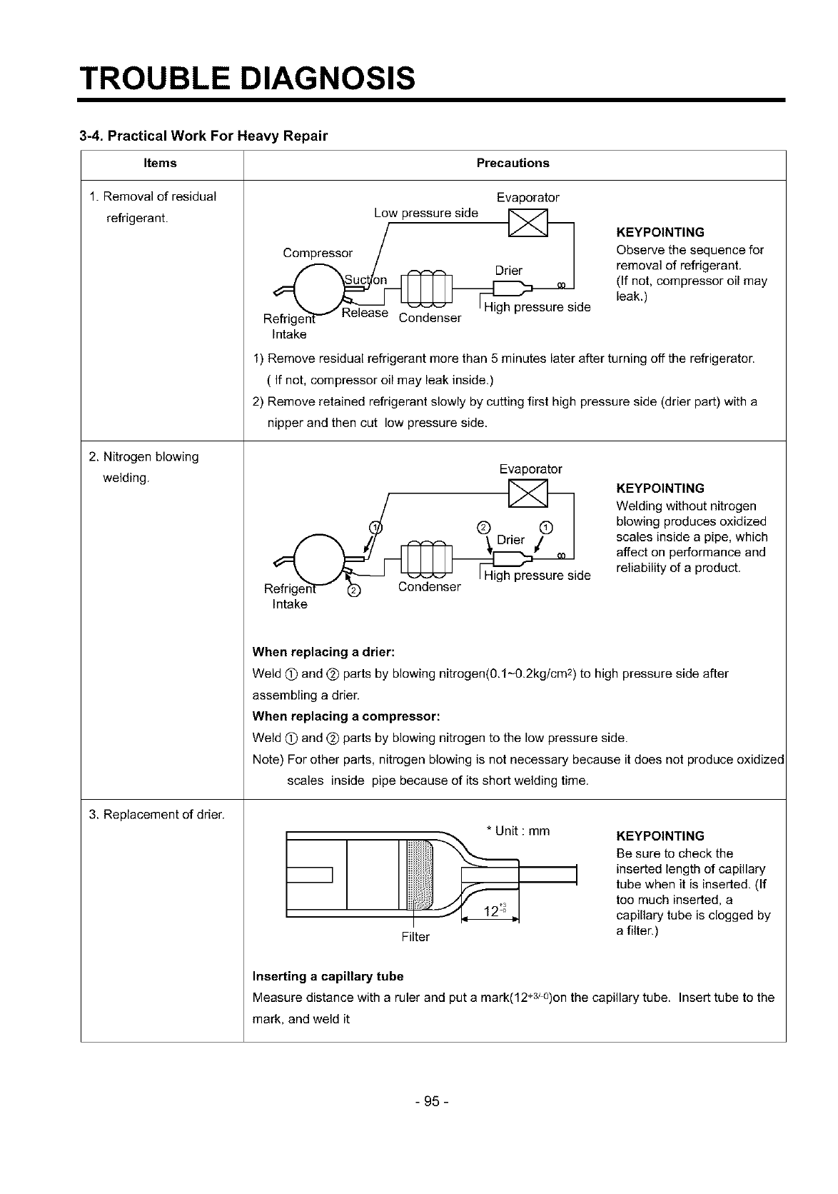
TROUBLE DIAGNOSIS
3-4. Practical Work For Heavy Repair
PrecautionsItems
1. Removal of residual
refrigerant.
2. Nitrogen blowing
welding.
3. Replacement of drier.
Evaporator
Compressor _/w pressure side
/_ Drier
j_ _ tHigh pressure side
R_enser --_ _ ......
Intake
KEYPOINTING
Observe the sequence for
removal of refrigerant.
(If not, compressor oil may
leak.)
1) Remove residual refrigerant more than 5 minutes later after turning off the refrigerator.
( If not, compressor oil may leak inside.)
2) Remove retained refrigerant slowly by cutting first high pressure side (drier part) with a
nipper and then cut low pressure side.
Evaporator
R_ side
Intake
KEYPOINTING
Welding without nitrogen
blowing produces oxidized
scales inside apipe, which
affect on performance and
reliability of a product.
When replacing a drier:
Weld (T) and (_) parts by blowing nitrogen(0.1-0.2kg/cm 2) to high pressure side after
assembling adrier.
When replacing a compressor:
Weld (_) and @ parts by blowing nitrogen to the low pressure side.
Note) For other parts, nitrogen blowing is not necessary because it does not produce oxidized
scales inside pipe because of its short welding time.
m]
Filter
*Unit : mm KEYPOINTING
Be sure to check the
i inserted length of capillary
tube when it is inserted. (If
too much inserted, a
capillary tube is clogged by
a filter.)
Inserting a capillary tube
Measure distance with a ruler and put a mark(12+3/0)on the capillary tube. Insert tube to the
mark, and weld it
- 95-

TROUBLE DIAGNOSIS
Items
4.Vacuum degassing.
5.Refrigerant charging.
Precautions
Evaporator
Suction pipe
Compressor
Dner
®
VaCCl
Blue
Low
pressure High
pressure
Red
Pipe Connection
Connect a red hose to the high pressure side and a blue hose to the
low pressure side.
Vacuum Sequence
Open (T), (_) valves and evacuate for 40 minutes. Close valve (T).
KEYPOINTING
- If power is applied
during vacuum
degassing, vacuum
degassing shall be
more effective.
- Operate compressor
while charging
refrigerant. (It is
easier and more
certain to do like
this.)
Charging sequence
1) Check the amount of refrigerant supplied to each model after completing vacuum
degassing.
2) Evacuate bombe with a vacuum pump.
3) Measure the amount of refrigerant charged.
Measure the weight of an evacuated bombe with an electronic scale.
- Charge refrigerant into a bombe and measure the weight. Calculate the weight of
refrigerant charged into the bombe by subtracting the weight of an evacuated bombe.
E_ Indicate the weight of
an evacuated bombe
R134a _)_
KEYPOINTING
Be sure to charge
the refrigerant at
around 25°C.
Be sure to keep -5g
in the winer and
+5g in summer
I Calculation of amount of refrigerant charged ]
the amount of refrigerant charged= a weight after charging
a weight before charging (a weight of an evacuated cylinder)
- 96 -
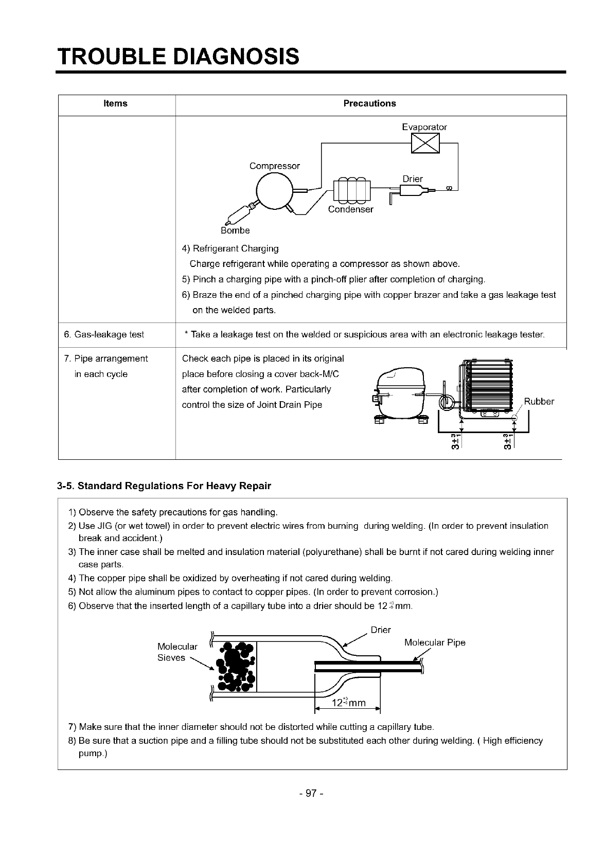
TROUBLE DIAGNOSIS
Items Precautions
6. Gasqeakage test
7. Pipe arrangement
in each cycle
Evaporator
Compressor
Condenser
Bombe
4) Refrigerant Charging
Charge refrigerant while operating a compressor as shown above.
5) Pinch a charging pipe with a pinch*off plier after completion of charging.
6) Braze the end of a pinched charging pipe with copper brazer and take a gas leakage test
on the welded parts.
*Take a leakage test on the welded or suspicious area with an electronic leakage tester.
Check each pipe is placed in its original _ :
, place before closing a cover back-M/C _ ['1_
after completion of work. Particularly • _ LI _i
control the size of Joint Drain Pipe _ I _ _._i ubber
3-5. Standard Regulations For Heavy Repair
1) Observe the safety precautions for gas handling.
2) Use JIG (or wet towel) in order to prevent electric wires from burning during welding. (In order to prevent insulation
break and accident.)
3) The inner case shall be melted and insulation material (polyurethane) shall be burnt if not cared during welding inner
case parts.
4) The copper pipe shall be oxidized by overheating if not cared during welding.
5) Not allow the aluminum pipes to contact to copper pipes. (In order to prevent corrosion.)
6) Observe that the inserted length of a capillary tube into a drier should be 12 ,;mm.
Drier
SievesM°lecular',,,,,,_,_// I _ Molecular_ Pipe
_ r
7) Make sure that the inner diameter should not be distorted while cutting a capillary tube.
8) Be sure that a suction pipe and a filling tube should not be substituted each other during welding. ( High efficiency
pump.)
- 97 -
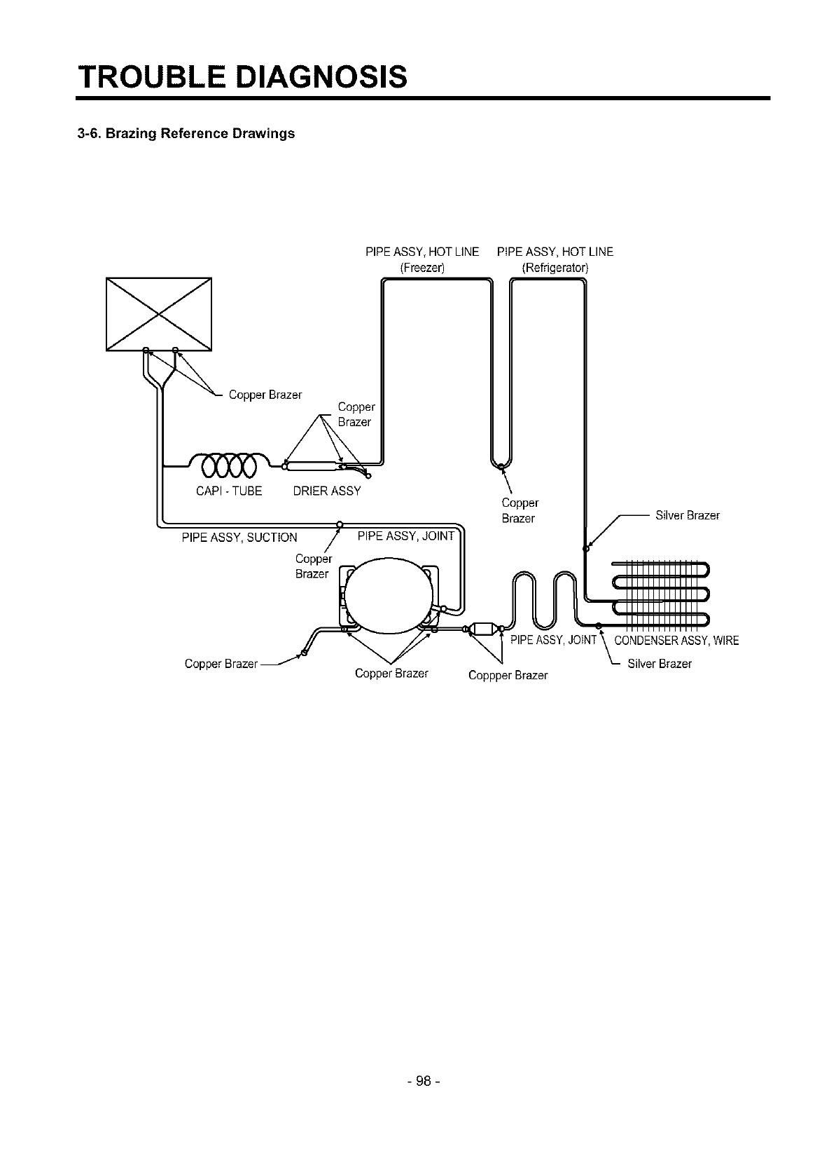
TROUBLE DIAGNOSIS
3-6. Brazing Reference Drawings
PIPE ASSY, HOT LINE
(Freezer)
Copper Brazer Copper
CAPI - TUBE DRIER ASSY
PIPE ASSY, SUCTION
Copper
Brazer
PIPE ASSY, HOT LINE
(Refrigerator)
Copper
Brazer
Copper Brazer Copper Brazer
JOINT\CONDENSER ASSY,WIRE
"- Silver Brazer
Coppper Brazer
- 98 -
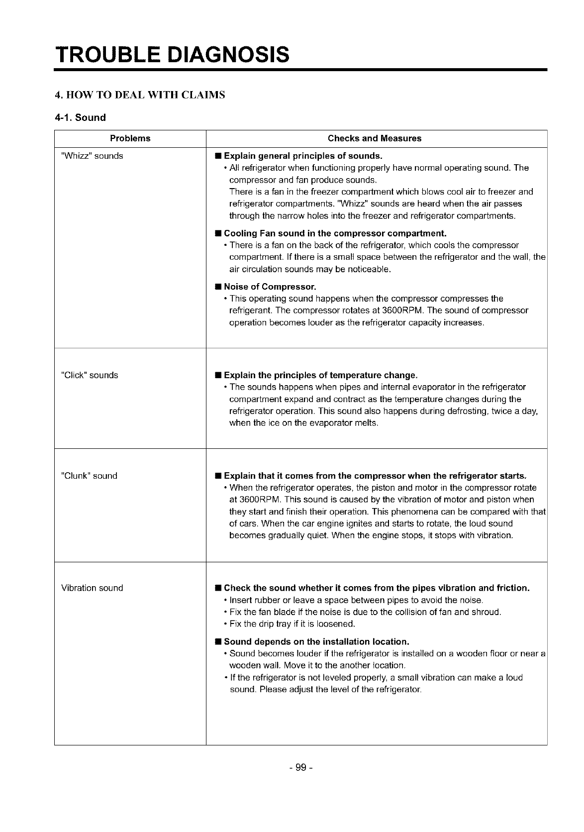
TROUBLE DIAGNOSIS
4. HOW TO DEAL WITH CLAIMS
4-1. Sound
Problems Checks and Measures
"Whizz" sounds
"Click"sounds
"Clunk"sound
Vibration sound
•Explain general principles of sounds.
•All refrigerator when functioning properly have normal operating sound. The
compressor and fan produce sounds.
There is a fan in the freezer compartment which blows cool air to freezer and
refrigerator compartments. "Whizz" sounds are heard when the air passes
through the narrow holes into the freezer and refrigerator compartments.
• Cooling Fan sound in the compressor compartment.
• There is a fan on the back of the refrigerator, which cools the compressor
compartment. If there is a small space between the refrigerator and the wall, the
air circulation sounds may be noticeable.
•Noise of Compressor.
•This operating sound happens when the compressor compresses the
refrigerant. The compressor rotates at 3600RPM. The sound of compressor
operation becomes louder as the refrigerator capacity increases.
• Explain the principles of temperature change.
• The sounds happens when pipes and internal evaporator in the refrigerator
compartment expand and contract as the temperature changes during the
refrigerator operation. This sound also happens during defrosting, twice a day,
when the ice on the evaporator melts.
• Explain that it comes from the compressor when the refrigerator starts.
• When the refrigerator operates, the piston and motor in the compressor rotate
at 3600RPM. This sound is caused by the vibration of motor and piston when
they start and finish their operation, This phenomena can be compared with that
of cars. When the car engine ignites and starts to rotate, the loud sound
becomes gradually quiet. When the engine stops, it stops with vibration.
•Check the sound whether it comes from the pipes vibration and friction.
• Insert rubber or leave a space between pipes to avoid the noise.
• Fix the fan blade if the noise is due to the collision of fan and shroud.
• Fix the drip tray if it is loosened.
•Sound depends on the installation location.
•Sound becomes louder if the refrigerator is installed on a wooden floor or near a
wooden wall. Move it to the another location.
• If the refrigerator is not leveled properly, a small vibration can make aloud
sound. Please adjust the level of the refrigerator.
- 99 -
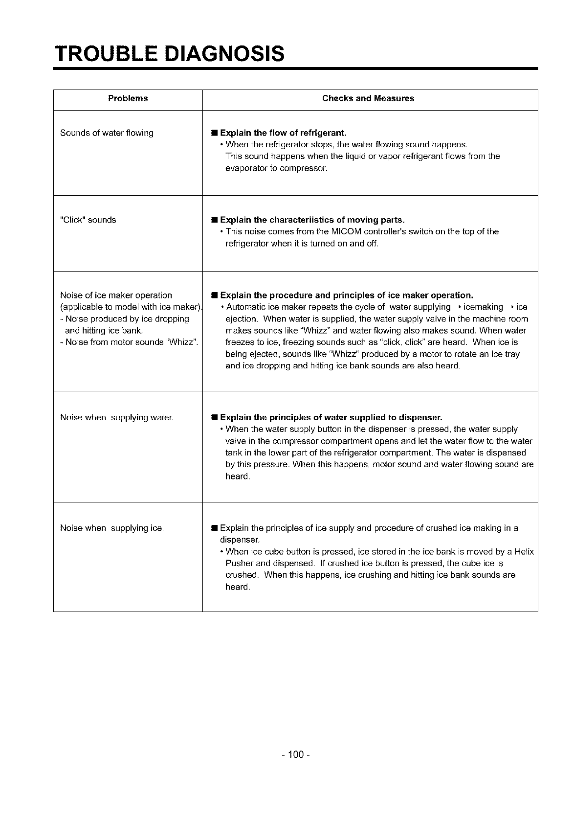
TROUBLE DIAGNOSIS
Problems Checks and Measures
Sounds of water flowing
"Click"sounds
Noise of ice maker operation
(applicable to model with ice maker
- Noise produced by ice dropping
and hitting ice bank.
- Noise from motor sounds "Whizz".
Noise when supplying water.
Noise when supplying ice.
• Explain the flow of refrigerant.
• When the refrigerator stops, the water flowing sound happens.
This sound happens when the liquid or vapor refrigerant flows from the
evaporator to compressor.
•Explain the characteriistics of moving parts.
• This noise comes from the MICOM controller's switch on the top of the
refrigerator when it is turned on and off.
•Explain the procedure and principles of ice maker operation.
• Automatic ice maker repeats the cycle of water supplying _ icemaking _ ice
ejection. When water is supplied, the water supply valve in the machine room
makes sounds like "Whizz" and water flowing also makes sound. When water
freezes to ice, freezing sounds such as "click, click" are heard. When ice is
being ejected, sounds like "Whizz" produced by a motor to rotate an ice tray
and ice dropping and hitting ice bank sounds are also heard.
•Explain the principles of water supplied to dispenser.
• When the water supply button in the dispenser is pressed, the water supply
valve in the compressor compartment opens and let the water flow to the water
tank in the lower part of the refrigerator compartment. The water is dispensed
by this pressure. When this happens, motor sound and water flowing sound are
heard.
• Explain the principles of ice supply and procedure of crushed ice making in a
dispenser.
• When ice cube button is pressed, ice stored in the ice bank is moved by a Helix
Pusher and dispensed. If crushed ice button is pressed, the cube ice is
crushed. When this happens, ice crushing and hitting ice bank sounds are
heard.
- 100 -
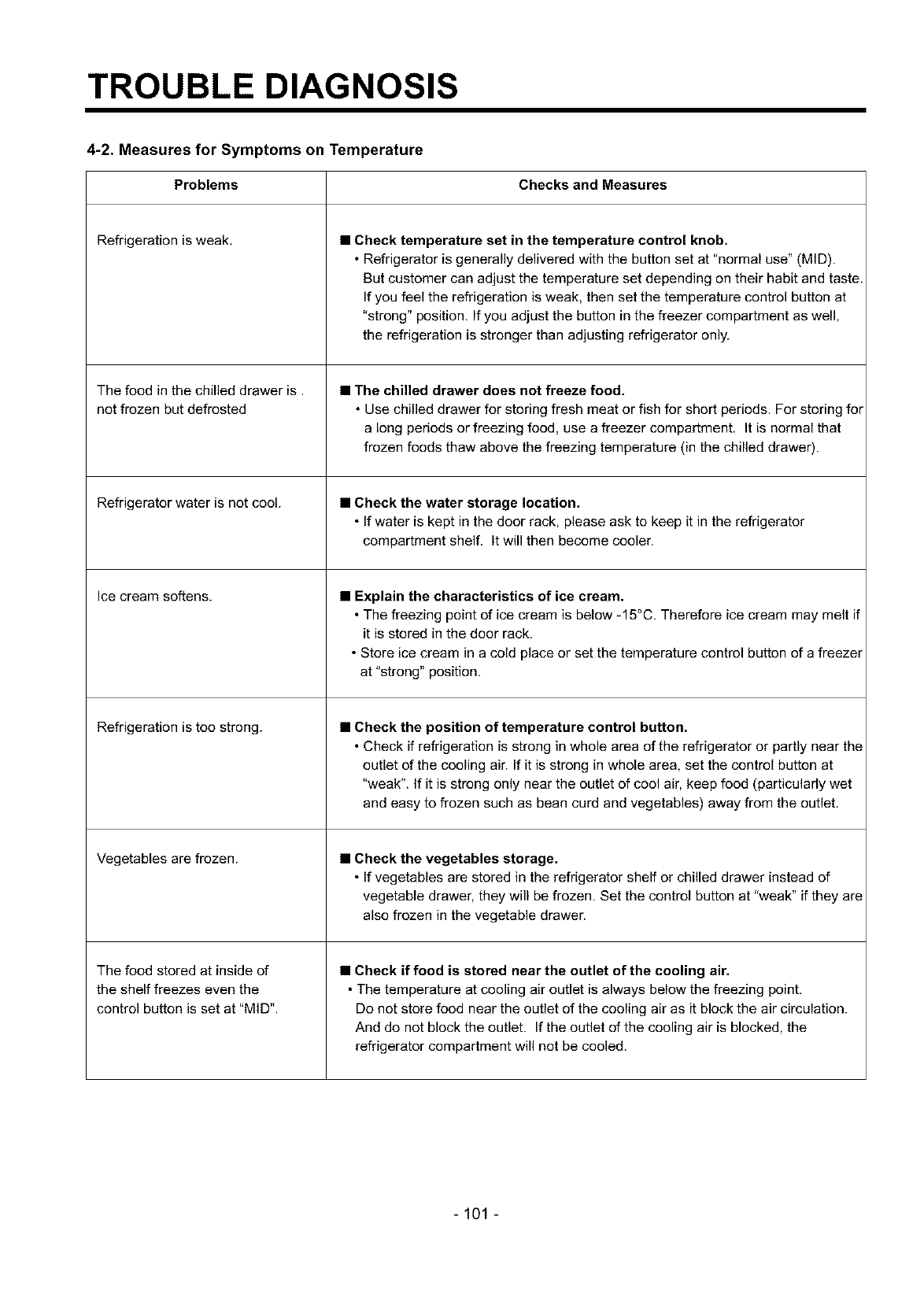
TROUBLE DIAGNOSIS
4-2. Measures for Symptoms on Temperature
Checks and MeasuresProblems
Refrigeration is weak.
The food in the chilled drawer is.
not frozen but defrosted
Refrigerator water is not cool.
Ice cream softens.
Refrigeration is too strong.
Vegetables are frozen.
The food stored at inside of
the shelf freezes even the
control button is set at "MID".
•Check temperature set in the temperature control knob.
• Refrigerator is generally delivered with the button set at "normal use" (MID).
But customer can adjust the temperature set depending on their habit and taste.
If you feel the refrigeration is weak, then set the temperature control button at
"strong" position. If you adjust the button in the freezer compartment as well,
the refrigeration is stronger than adjusting refrigerator only.
•The chilled drawer does not freeze food.
• Use chilled drawer for storing fresh meat or fish for short periods. For storing for
along periods or freezing food, use a freezer compartment. It is normal that
frozen foods thaw above the freezing temperature (in the chilled drawer).
•Check the water storage location.
• If water is kept in the door rack, please ask to keep it in the refrigerator
compartment shelf. It will then become cooler.
• Explain the characteristics of ice cream.
• The freezing point of ice cream is below -15°C. Therefore ice cream may melt if
it is stored in the door rack.
• Store ice cream in acold place or set the temperature control button of a freezer
at "strong" position.
•Check the position of temperature control button.
• Check if refrigeration is strong in whole area of the refrigerator or partly near the
outlet of the cooling air. If it is strong in whole area, set the control button at
"weak". If it is strong only near the outlet of cool air, keep food (particularly wet
and easy to frozen such as bean curd and vegetables) away from the outlet.
• Check the vegetables storage.
• If vegetables are stored in the refrigerator shelf or chilled drawer instead of
vegetable drawer, they will be frozen. Set the control button at "weak" if they are
also frozen in the vegetable drawer.
• Check if food is stored near the outlet of the cooling air.
• The temperature at cooling air outlet is always below the freezing point.
Do not store food near the outlet of the cooling air as it block the air circulation.
And do not block the outlet. If the outlet of the cooling air is blocked, the
refrigerator compartment will not be cooled.
- 101 -
TROUBLE DIAGNOSIS
4-3. Odor and Frost
Checks and MeasuresProblems
Odor in the refrigerator compartment.
Frost in the freezer compartment
Frost in ice tray.
• Explain the basic principles of food odor.
• Each food has its own peculiar odor. Therefore it is impossible to prevent or
avoid food odor completely when food is stored in the completely sealed
refrigerator compartment. Deodorizer can absorb some portions of the odor but
not completely. The intensity of odor depends on refrigerator conditions and
environments.
•Check the temperature control button and set at "strong".
• Clean inside of the refrigerator with detergent and remove moisture. Dry inside
the refrigerator by opening the door for about 3 or 4 hours and then set the
temperature control button at "strong".
• Explain the basic principles of frost formation,
• The main causes for frosting:
- Door was left open.
- Air penetration through the gasket
- Too frequent door opening. (parties. etc.)
- Hot foods are stored before they are cooled down. The temperature of freezer
is -19°C. if temperature is set at "MID". If hot air comes into the refrigerator,
fine frost forms as cold air mixes with hot air, If this happens quite often, much
frost forms inside of the refrigerator. If the door is left open in Summer, ice may
form inside of the refrigerator.
• Explain basic principles of frost formation.
• When ice tray with full of water is put into a freezer compartment, the water
evaporates. If cool air fan operates, the moisture attached to the jaw (protruded
part) of ice mold shall freeze and form frost. If warm water was put into the ice
mold, the situation will become worse.
- 102 -
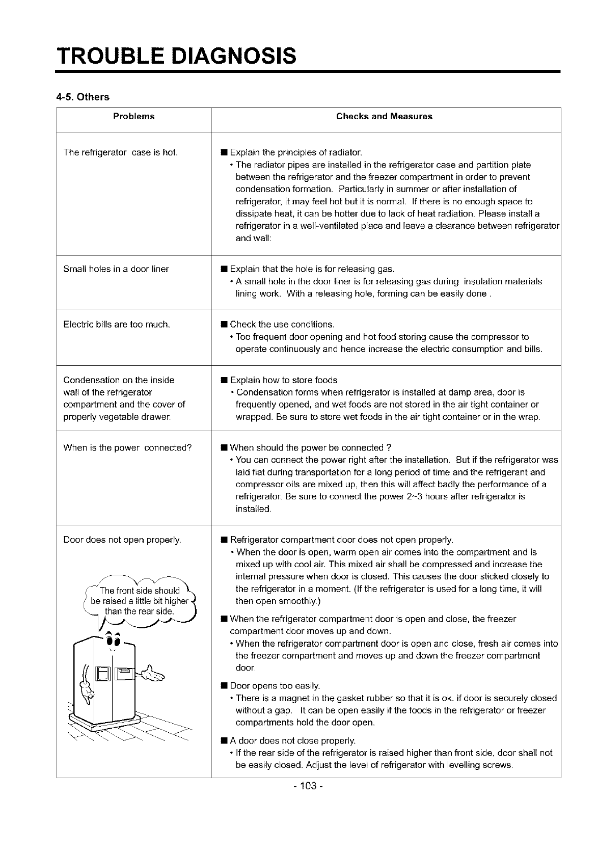
TROUBLE DIAGNOSIS
4-5. Others
Problems Checks and Measures
The refrigerator case is hot.
Small holes in a door liner
Electric bills are too much.
Condensation on the inside
wall of the refrigerator
compartment and the cover of
properly vegetable drawen
When is the power connected?
Door does not open properly.
• Explain the principles of radiator.
• The radiator pipes are installed in the refrigerator case and partition plate
between the refrigerator and the freezer compartment in order to prevent
condensation formation. Particularly in summer or after installation of
refrigerator, it may feel hot but it is normal. If there is no enough space to
dissipate heat, it can be hotter due to lack of heat radiation. Please install a
refrigerator in a well-ventilated place and leave a clearance between refrigerator
and wall:
• Explain that the hole is for releasing gas.
• A small hole in the door liner is for releasing gas during insulation materials
lining work. With a releasing hole, forming can be easily done.
• Check the use conditions.
• Too frequent door opening and hot food storing cause the compressor to
operate continuously and hence increase the electric consumption and bills.
• Explain how to store foods
• Condensation forms when refrigerator is installed at damp area, door is
frequently opened, and wet foods are not stored in the air tight container or
wrapped. Be sure to store wet foods in the air tight container or in the wrap.
• When should the power be connected ?
• You can connect the power right after the installation. But if the refrigerator was
laid flat during transportation for a long period of time and the refrigerant and
compressor oils are mixed up, then this will affect badly the performance of a
refrigerator. Be sure to connect the power 2-3 hours after refrigerator is
installed.
• Refrigerator compartment door does not open properly.
• When the door is open, warm open air comes into the compartment and is
mixed up with cool air. This mixed air shall be compressed and increase the
internal pressure when door is closed. This causes the door sticked closely to
the refrigerator in a moment. (If the refrigerator is used for a long time, it will
then open smoothly.)
• When the refrigerator compartment door is open and close, the freezer
compartment door moves up and down.
• When the refrigerator compartment door is open and close, fresh air comes into
the freezer compartment and moves up and down the freezer compartment
door.
• Door opens too easily.
• There is a magnet in the gasket rubber so that it is ok. if door is securely closed
without a gap. It can be open easily if the foods in the refrigerator or freezer
compartments hold the door open.
• A door does not close properly.
• If the rear side of the refrigerator is raised higher than front side, door shall not
be easily closed. Adjust the level of refrigerator with levelling screws.
- 103 -
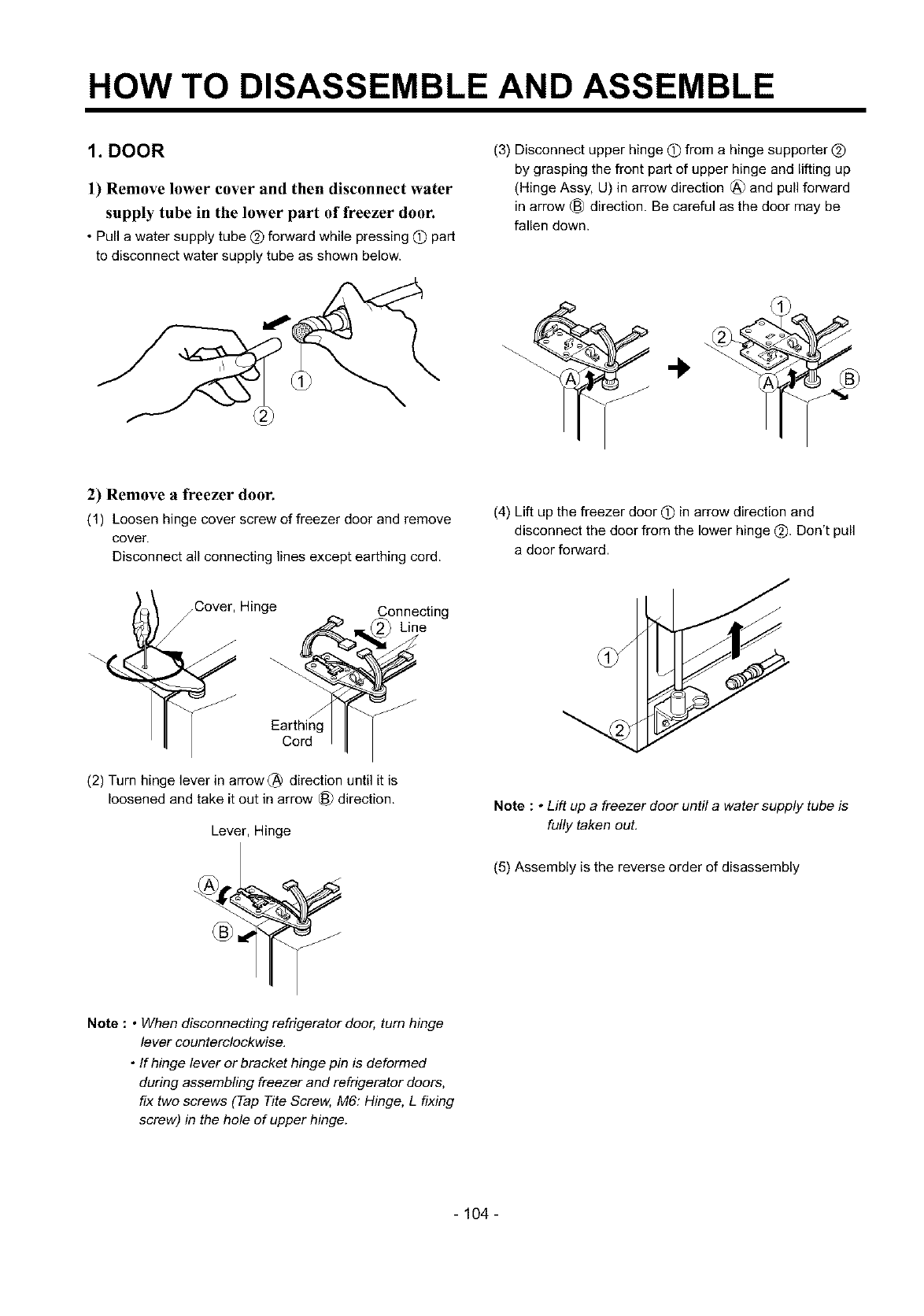
HOW TO DISASSEMBLE AND ASSEMBLE
1. DOOR
1) Remove lower cover and then disconnect water
supply tube in the lower part of freezer door.
•Pull a water supply tube @ forward while pressing (_)part
to disconnect water supply tube as shown below.
(3) Disconnect upper hinge 0 from a hinge supporter @
by grasping the front part of upper hinge and lifting up
(Hinge Assy, U) in arrow direction _) and pull forward
in arrow _) direction. Be careful as the door may be
fallen down.
2) Remove a freezer door.
(1) Loosen hinge cover screw of freezer door and remove
cover.
Disconnect all connecting lines except earthing cord.
(4) Lift up the freezer door (_) in arrow direction and
disconnect the door from the lower hinge Q. Don't pull
a door forward.
_Cover, Hinge
/
Earthing
Cord
(2) Turn hinge lever in arrow (_ direction until it is
loosened and take it out in arrow (_ direction.
Lever, Hinge
Connecting
_ Line
Note :•Lift up a freezer door until a water supply tube is
fully taken out.
(5) Assembly is the reverse order of disassembly
Note : • When disconnecting refrigerator door, turn hinge
lever counterclockwise.
•If hinge lever or bracket hinge pin is deformed
during assembling freezer and refrigerator doors,
fix two screws (Tap Tite Screw, M6: Hinge, L fixing
screw) in the hole of upper hinge.
- 104 -
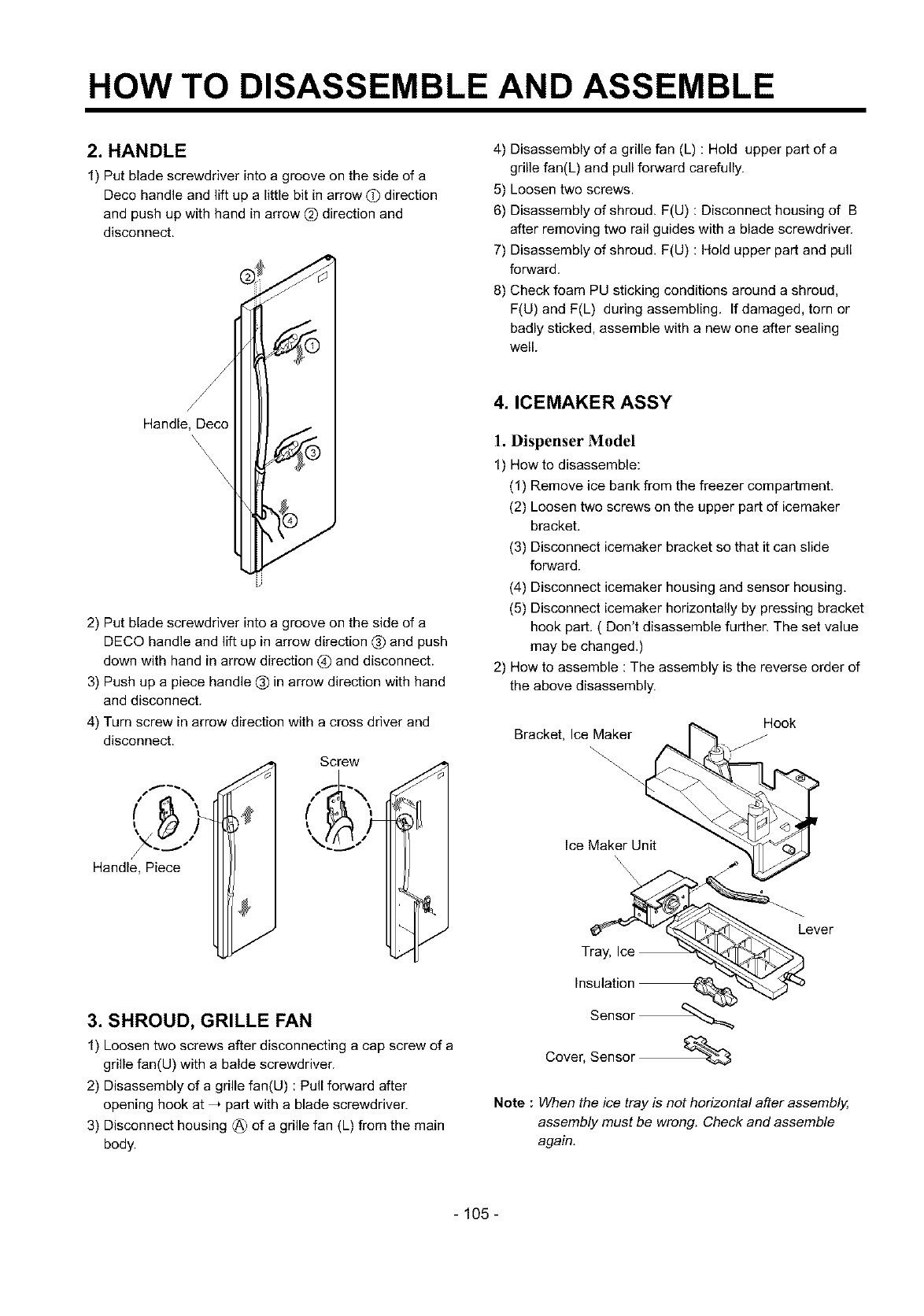
HOW TO DISASSEMBLE AND ASSEMBLE
2. HANDLE
1) Put blade screwdriver into a groove on the side of a
Deco handle and lift up alittle bit in arrow (!) direction
and push up with hand in arrow (_)direction and
disconnect.
4) Disassembly of a grille fan (L) : Hold upper part of a
grille fan(L) and pull forward carefully.
5) Loosen two screws.
6) Disassembly of shroud. F(U) : Disconnect housing of B
after removing two rail guides with a blade screwdriver.
7) Disassembly of shroud. F(U) : Hold upper part and pull
forward.
8) Check foam PU sticking conditions around a shroud,
F(U) and F(L) during assembling. If damaged, torn or
badly sticked, assemble with anew one after sealing
well.
Handle, Deco
2) Put blade screwdriver into a groove on the side of a
DECO handle and lift up in arrow direction (_ and push
down with hand in arrow direction _) and disconnect.
3) Push up a piece handle (_) in arrow direction with hand
and disconnect.
4) Turn screw in arrow direction with a cross driver and
disconnect.
Screw
Handle, Piece
3. SHROUD, GRILLE FAN
1) Loosen two screws after disconnecting a cap screw of a
grille fan(U) with a balde screwdriver.
2) Disassembly of a grille fan(U) : Pull forward after
opening hook at _ part with a blade screwdriver.
3) Disconnect housing (_ of a grille fan (L) from the main
body.
4. ICEMAKER ASSY
1. Dispenser Model
1) How to disassemble:
(1) Remove ice bank from the freezer compartment.
(2) Loosen two screws on the upper part of icemaker
bracket.
(3) Disconnect icemaker bracket so that it can slide
forward.
(4) Disconnect icemaker housing and sensor housing.
(5) Disconnect icemaker horizontally by pressing bracket
hook part. ( Don't disassemble further. The set value
may be changed.)
2) How to assemble : The assembly is the reverse order of
the above disassembly.
Hook
Bracket, Ice Maker
Ice Maker Unit
Tray, Ice
Insulation
Sensor _
Cover, Sensor
Lever
Note : When the ice tray is not horizontal after assembly,
assembly must be wrong. Check and assemble
again.
- 105-
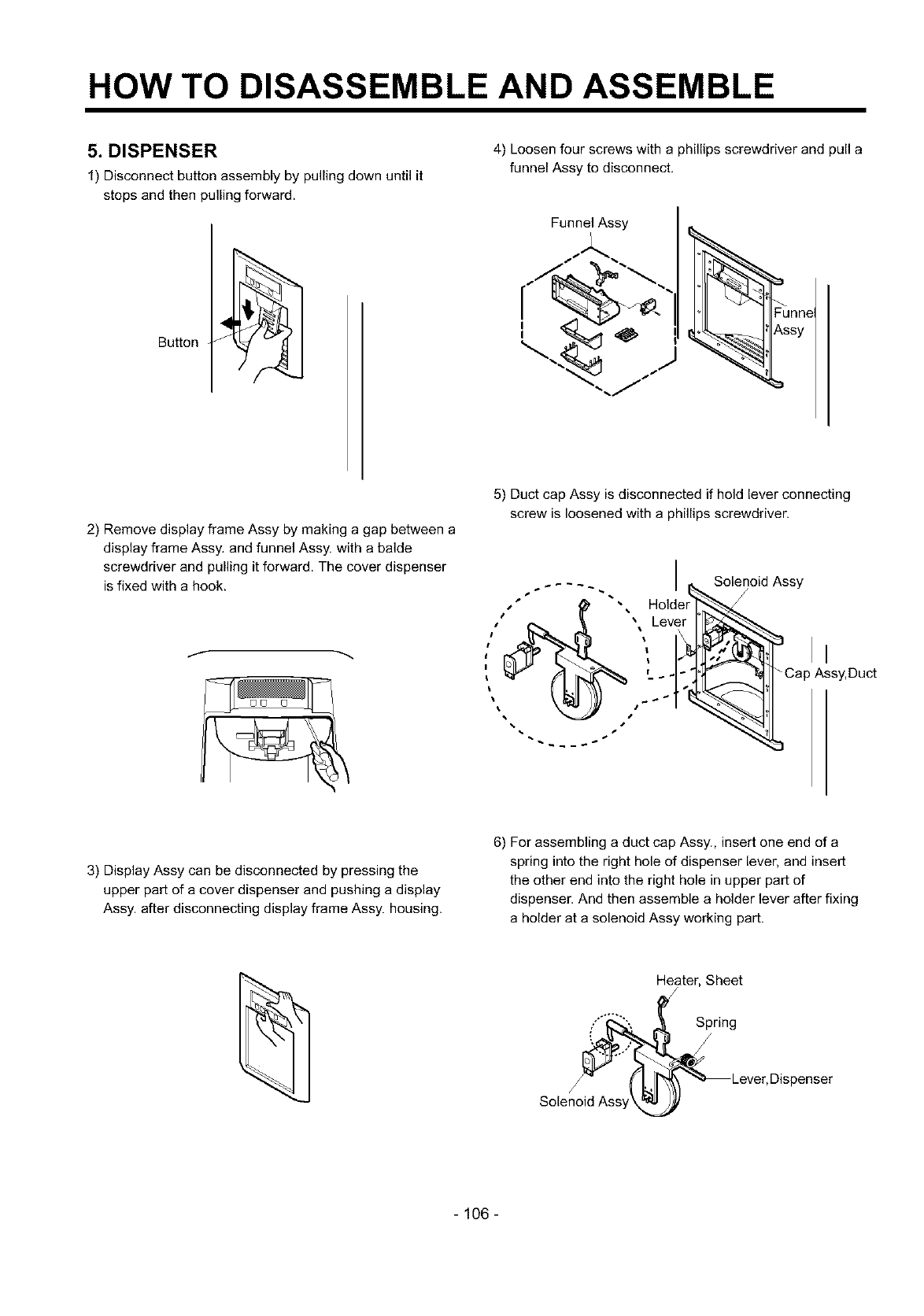
HOW TO DISASSEMBLE AND ASSEMBLE
5. DISPENSER
1) Disconnect button assembly by pulling down until it
stops and then pulling forward.
Button
4) Loosen four screws with a phillips screwdriver and pull a
funnel Assy to disconnect.
Funnel Assy
' <
' _:::__'
\..<
Funne
Assy
2) Remove display frame Assy by making a gap between a
display frame Assy. and funnel Assy. with a balde
screwdriver and pulling it forward. The cover dispenser
is fixed with a hook.
5) Duct cap Assy is disconnected if hold lever connecting
screw is loosened with a phillips screwdriver.
Solenoid Assy
/
II
Cap Assy, Duct
3) Display Assy can be disconnected by pressing the
upper part of a cover dispenser and pushing a display
Assy. after disconnecting display frame Assy. housing.
6) For assembling a duct cap Assy., insert one end of a
spring into the right hole of dispenser lever, and insert
the other end into the right hole in upper part of
dispenser. And then assemble a holder lever after fixing
a holder at a solenoid Assy working part.
Heater, Sheet
Solenc_" _ 'L'II'_A__Lever, Dispenser
- 106 -
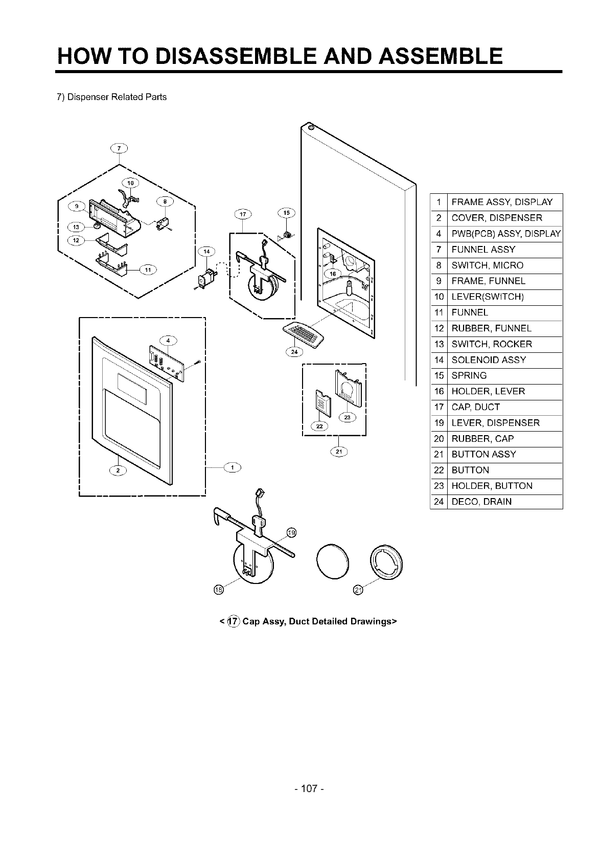
HOW TO DISASSEMBLE AND ASSEMBLE
7) Dispenser Related Parts
T
1 FRAME ASSY, DISPLAY
2 COVER, DISPENSER
4 PWB(PCB) ASSY, DISPLAY
7 FUNNELASSY
8 SWITCH, MICRO
9 FRAME, FUNNEL
10 LEVER(SWITCH)
11 FUNNEL
12 RUBBER, FUNNEL
13 SWITCH, ROCKER
14 SOLENOID ASSY
15 SPRING
16 HOLDER, LEVER
17 CAP, DUCT
19 LEVER, DISPENSER
20 RUBBER, CAP
21 BUTTON ASSY
22 BUTTON
23 HOLDER, BUTTON
24 DECO, DRAIN
<@Cap Assy, Duct Detailed Drawings>
- 107-
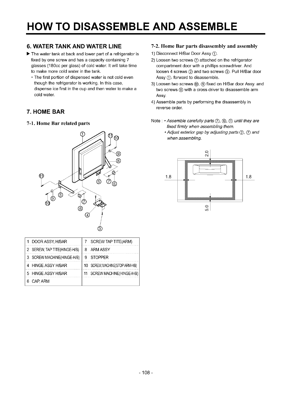
HOW TO DISASSEMBLE AND ASSEMBLE
6. WATER TANK AND WATER LINE
• The water tank at back and lower part of a refrigerator is
fixed by one screw and has a capacity containing 7
glasses (180cc per glass) of cold water. It will take time
to make more cold water in the tank.
* The first portion of dispensed water is not cold even
though the refrigerator is working. In this case,
dispense ice first in the cup and then water to make a
cold water.
7. HOME BAR
7-1. Home Bar related parts
%2. Home Bar parts disassembly and assembly
1) Disconnect H/Bar Door Assy (D
2) Loosen two screws (_) attached on the refrigerator
compartment door with a phillips screwdriver. And
loosen 4 screws @ and two screws (_). Pull HIBar door
Assy (_), forward to disassemble,
3) Loosen two screws _), _) fixed on HIBar door Assy, and
two screws (_) with a cross driver to disassemble arm
Assy,
4) Assemble parts by performing the disassembly in
reverse order.
Note : •Assemble carefully parts (Z), (_, @ until they are
fixed firmly when assembling them.
•Adjust exteriorgap by adjusting parts _), (_) and
when assembling.
1.8 1.8
oT
.5
1 DOORASSY, H/BAR 7 SCREWTAPTITE(ARM)
2 SEREW,TAPTffE(HINGE-H/B) 8 ARMASSY
3 SCREWMACHINE(HINGE-H/B)9 STOPPER
4 HINGEASSYH/BAR 10 SCREW,MACHINE(STOPARiv_H/B)
5 HINGEASSYH/BAR 11 SCREWMACHINE(HINGE-H/B)
6 CAP,ARM
- 108 -
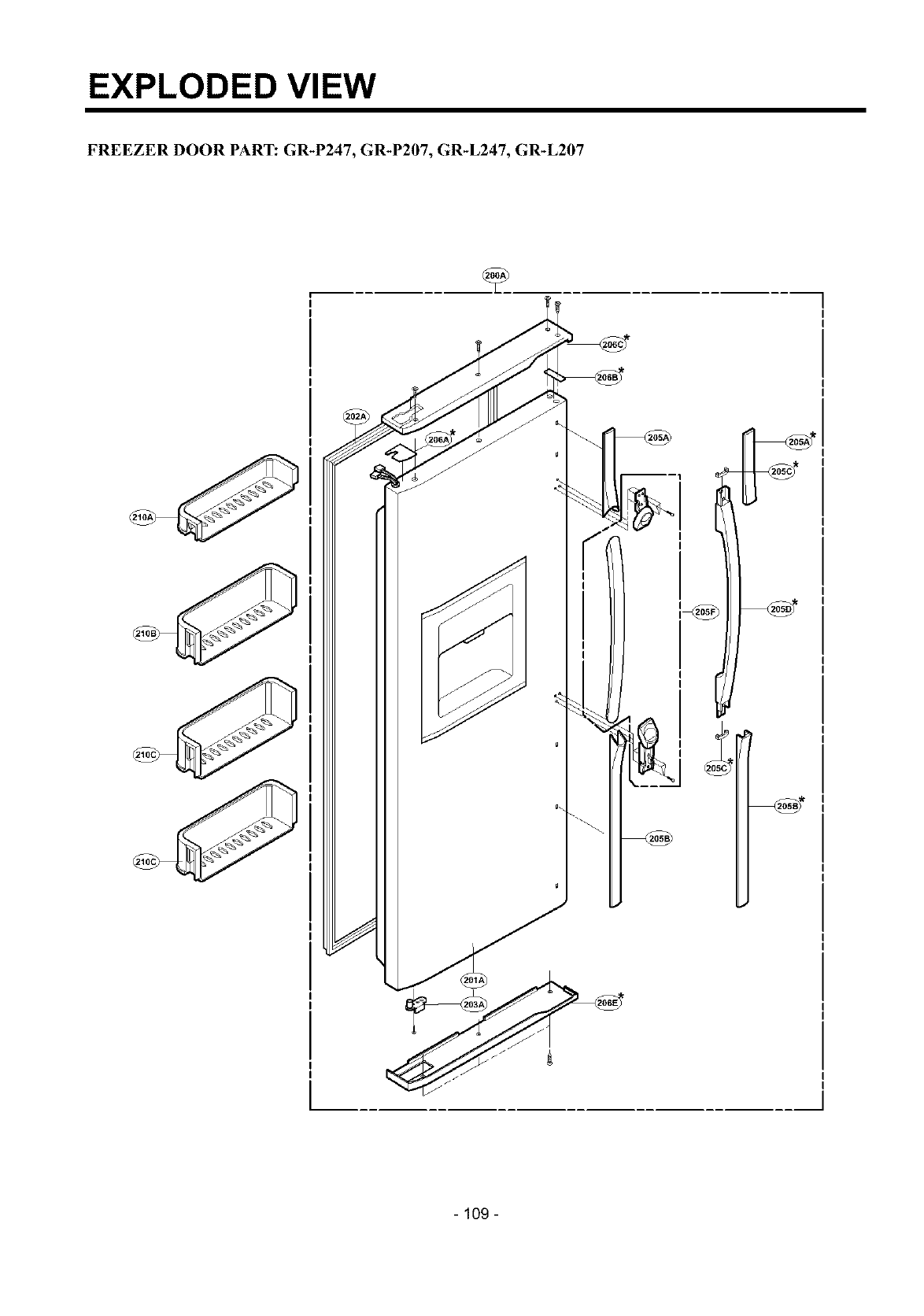
EXPLODED VIEW
FREEZER DOOR PART: GR-P247, GR-P207, GR-L247, GR-L207
I
- 109 -
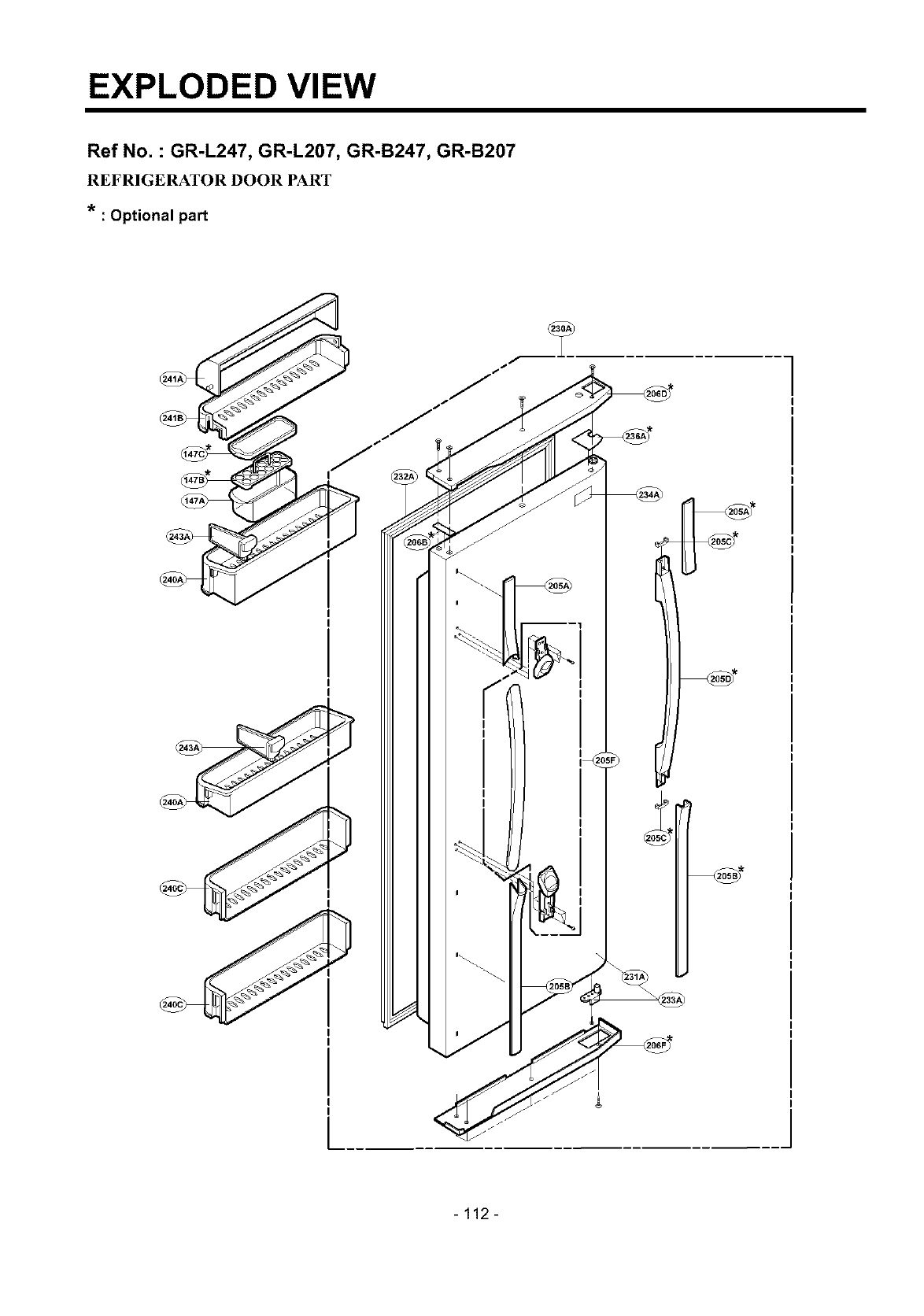
EXPLODED VIEW
Ref No. : GR-L247, GR-L207, GR-B247, GR-B207
REFRIGERATOR DOOR PART
* : Optional part
-112 -
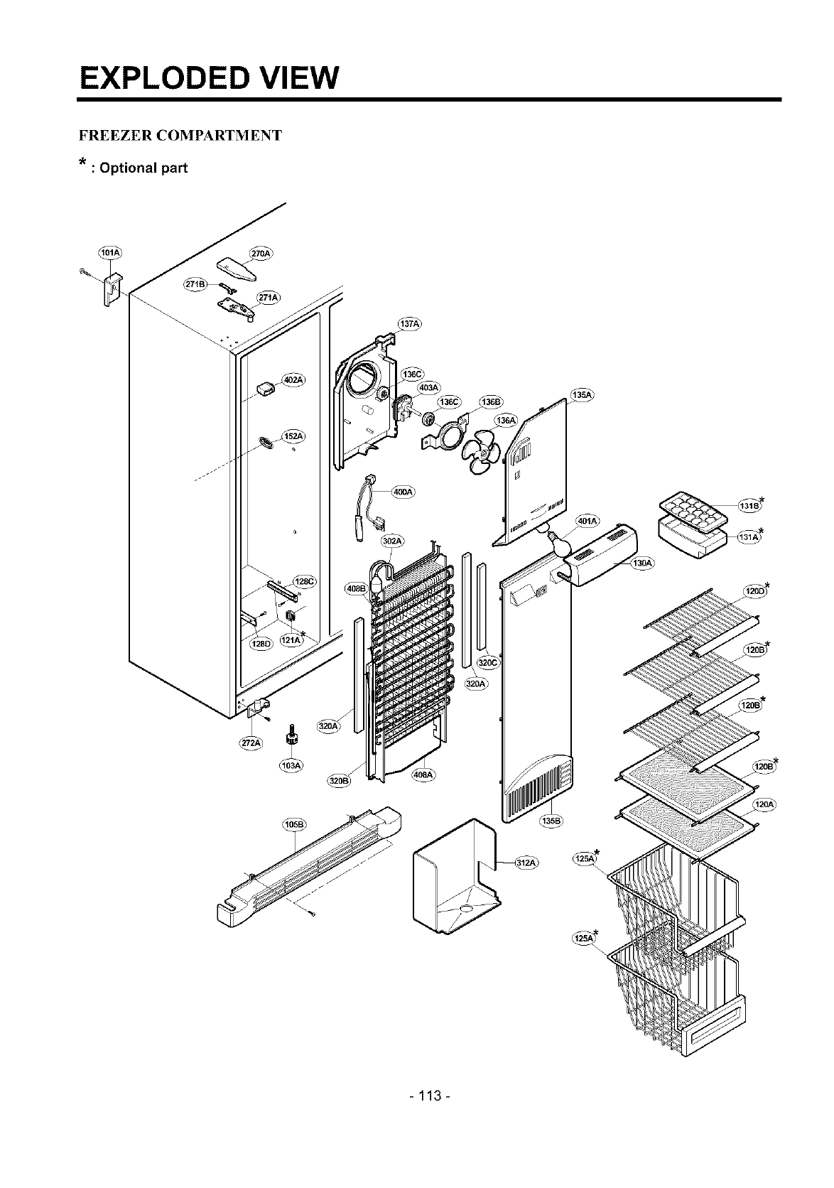
EXPLODED VIEW
FREEZER COMPARTMENT
* : Optional part
- 113 -
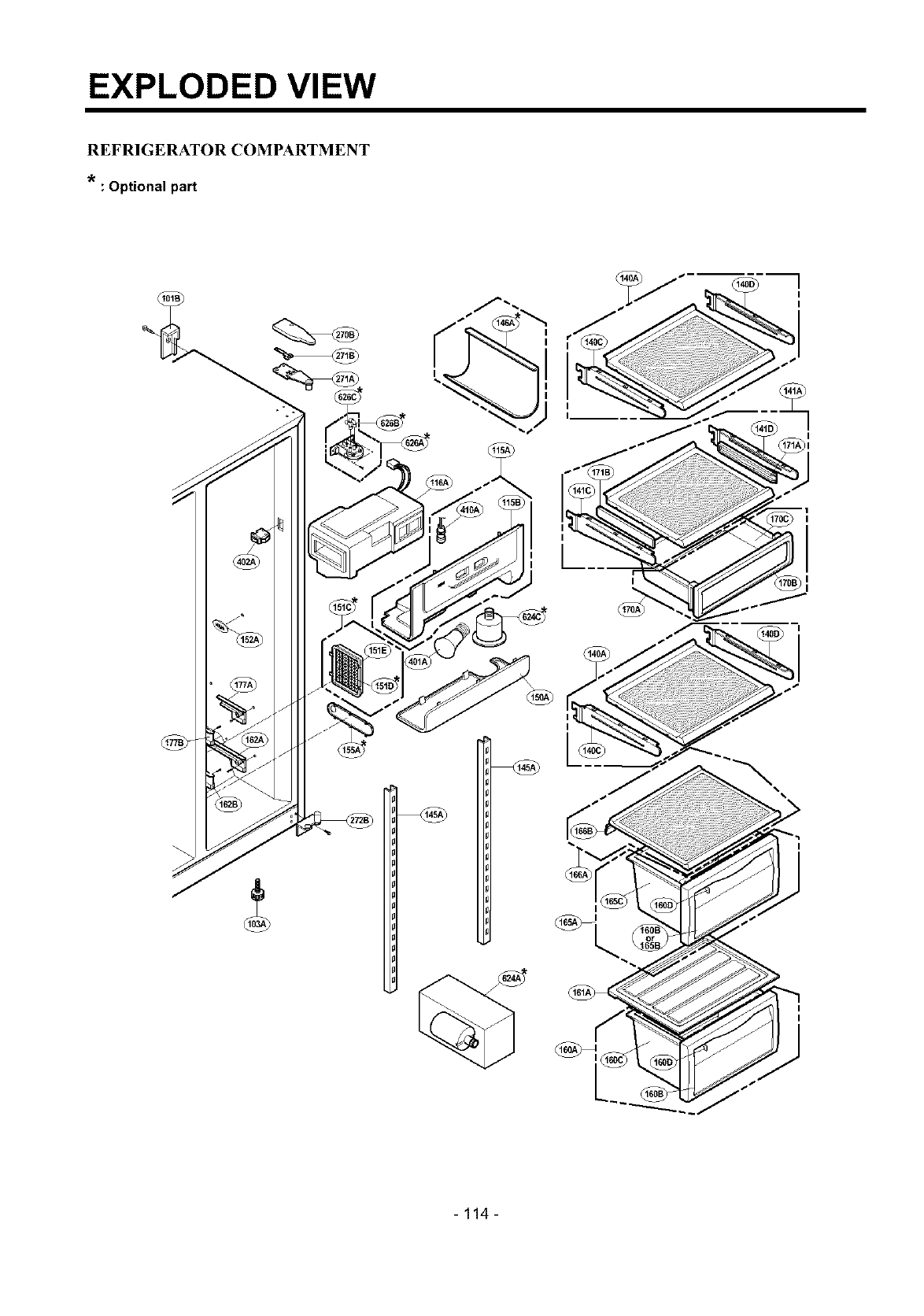
EXPLODED VIEW
REFRIGERATOR COMPARTMENT
: Optional part
I
I
-114-
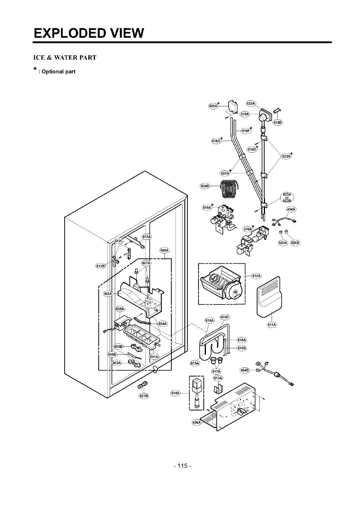
EXPLODED VIEW
ICE & WATER PART
: Optional part
- 115-
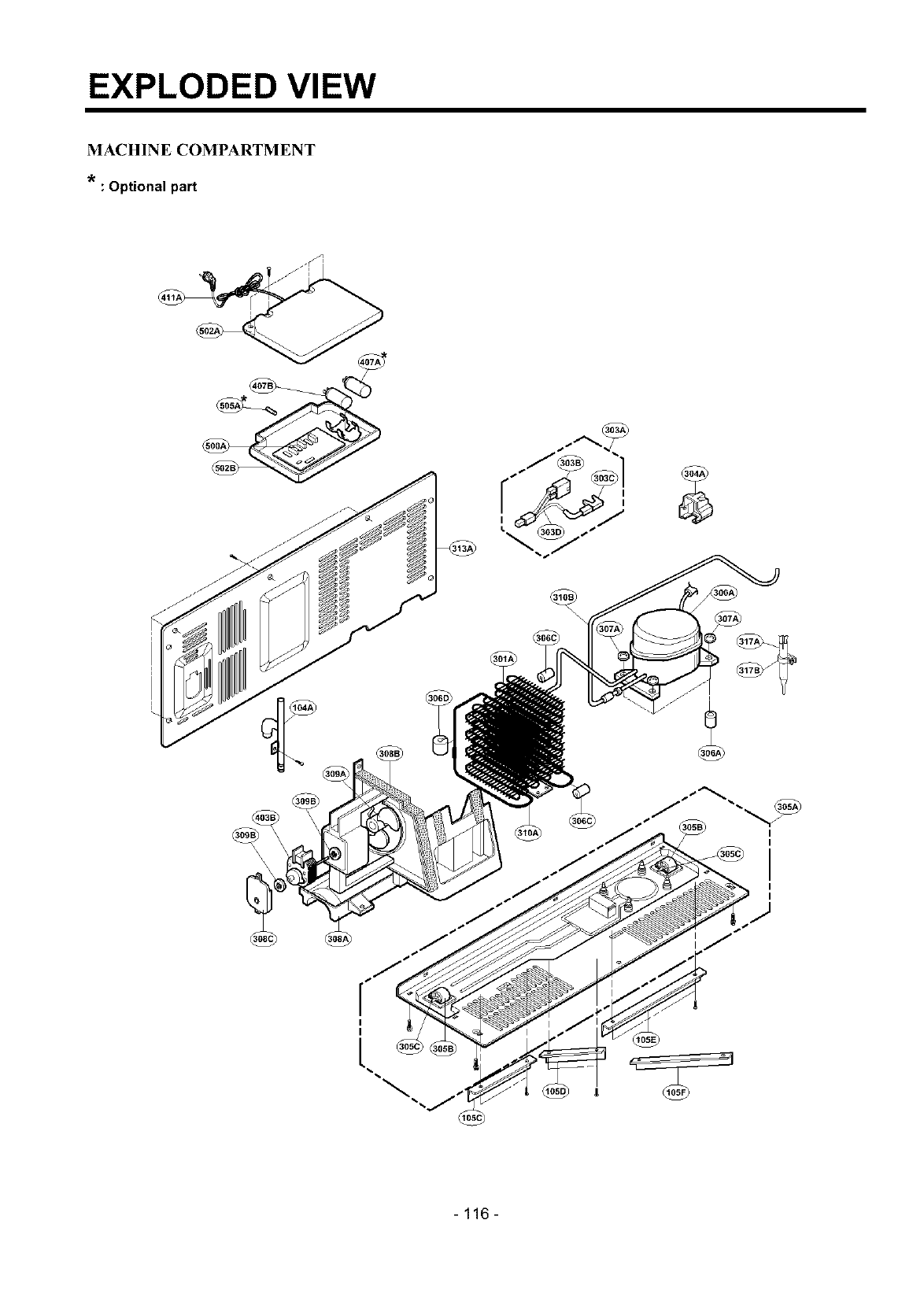
EXPLODED VIEW
MACHINE COMPARTMENT
: Optional part
I
I
- 116 -
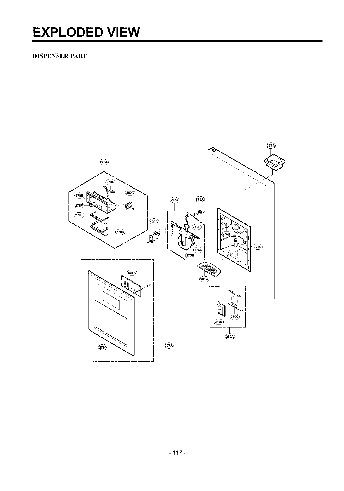
EXPLODED VIEW
DISPENSER PART
I
I
L.._.
- 117 -
