LG LRTBC2025T User Manual REFRIGERATOR Manuals And Guides L0301141
LG Top Mount Refrigerator Manual L0301141 LG Top Mount Refrigerator Owner's Manual, LG Top Mount Refrigerator installation guides
User Manual: LG LRTBC2025T LRTBC2025T LG REFRIGERATOR - Manuals and Guides View the owners manual for your LG REFRIGERATOR #LRTBC2025T. Home:Kitchen Appliance Parts:LG Parts:LG REFRIGERATOR Manual
Open the PDF directly: View PDF ![]() .
.
Page Count: 28
SERVICING PRECAUTIONS
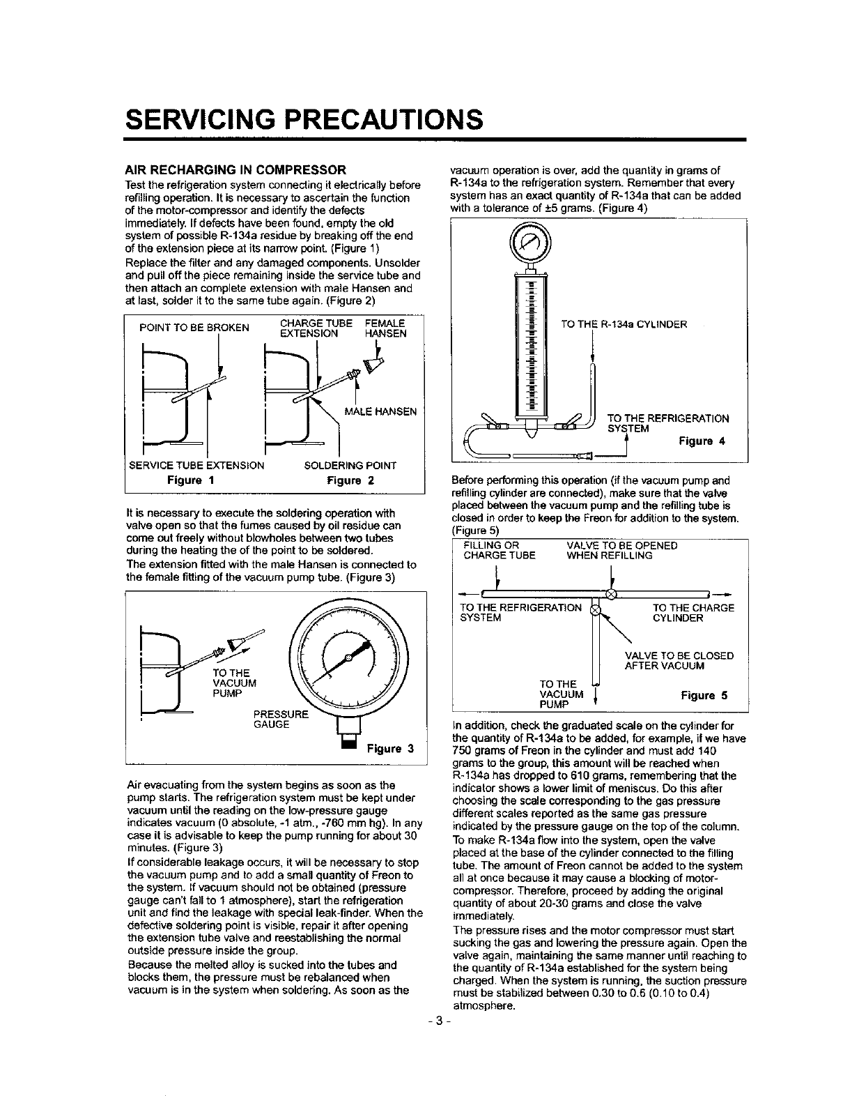
AIR RECHARGING IN COMPRESSOR
Test the refrigeration system connecting it electrically before
refilling operation. It is necessary to ascertain the function
of the motor-compressor and identify the defects
immediately. If defects have been found, empty the old
system of possible R-134a residue by breaking off the end
of the extension piece at its narrow point. (Figure 1)
Replace the filter and any damaged components. Unsolder
and pull off the piece remaining inside the service tube and
then attach an complete extension with male Hansen and
at last, solder itto the same tube again. (Figure 2)
POINT TO BE BROKEN CHARGE TUBE FEMALE
EXTENSION HANSEN
,_ MALE HANSEN
SERVICE TUBE EXTENSION SOLDERING POINT
Figure 1 Figure 2
It is necessary to execute the soldering operation with
valve open so that the fumes caused by oil residue can
come out freely without blowhetes between two tubes
during the heating the of the point to be soldered.
The extension fitted with the male Hansen is connected to
the female fitting of the vacuum pump tube. (Figure 3)
GAUGE
Figure 3
Air evacuating from the system begins as soon as the
pump starts. The refrigeration system must be kept under
vacuum until the reading on the low-pressure gauge
indicates vacuum (0 absolute, -1 atm., -760 mm hg). In any
case it is advisable to keep the pump running for about 30
minutes. (Figure 3)
If considerable leakage occurs, it will be necessary to stop
the vacuum pump and to add a small quantity of Freon to
the system. If vacuum should not be obtained (pressure
gauge can't fall to fatmosphere), start the refrigeration
unit and find the leakage with special leak-finder. When the
defective soldering point is visible, repair it after opening
the extension tube valve and reestablishing the normal
outside pressure inside the group.
Because the melted alloy is sucked into the tubes and
blocks them, the pressure must be rebalanced when
vacuum is in the system when soldering. As soon as the
vacuum operation is over, add the quantity in grams of
R-134a to the refrigeration system. Remember that every
system has an exact quantity of R-134a that can be added
with a tolerance of +5 grams. (Figure 4)
TO THE R-134a CYLINDER
_,, _ TO THE REFRIGERATION
SYITEM Figure 4
Before performing this operation (if the vacuum pump and
refilling cylinder are connected), make sure that the valve
placed between the vacuum pump and the refilling tube is
closed in order to keep the Freon for addition to the system.
(Figure 5)
FILLING OR VALVE TO BE OPENED
CHARGE TUBE WHEN REFILLING
TO THE REFRIGERATION TO THE CHARGE
SYSTEM CYLINDER
VALVE TO BE CLOSED
AFTER VACUUM
TO THE
VACUUM _Figure 5
PUMP
In add:tion, check the graduated scale on the cylinder for
the quantity of R-134a to be added, for example, if we have
750 grams of Freon in the cylinder and must add 140
grams to the group, this amount will be reached when
R-134a has dropped to 610 grams, remembering that the
indicator shows a lower limit of meniscus. Do this after
choosing the scale corresponding to the gas pressure
different scales reported as the same gas pressure
indicated by the pressure gauge on the top of the column.
To make R-134a flow into the system, open the valve
placed at the base of the cylinder connected to the filling
tube. The amount of Freon cannot be added to the system
all at once because it may cause a blocking of motor-
compressor. Therefore, proceed by adding the original
quantity of about 20-30 grams and close the vane
immediately.
The pressure rises and the motor compressor must start
sucking the gas and lowering the pressure again. Open the
valve again, maintaining the same manner until reaching to
the quantity of R-134a established for the system being
charged. When the system is running, the suction pressure
must be stabilized between 0.30 to 0.6 (0.10 to 0.4)
atmosphere.
-3-
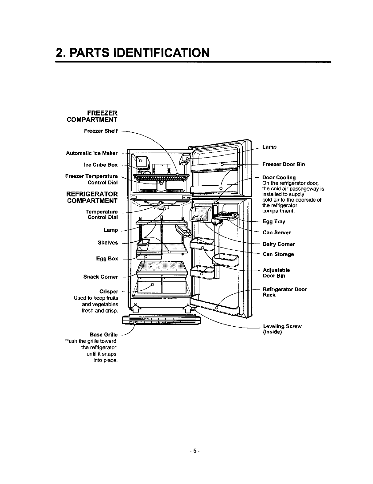
2. PARTS IDENTIFICATION
FREEZER
COMPARTMENT
Freezer Shelf
Automatic Ice Maker
tce Cube Box
Freezer Temperature
Control Dial
REFRIGERATOR
COMPARTMENT
Temperature
Control Dial
Lamp
Shelves
Egg Box
Snack Corner
Crisper
Used to keep fruits
and vegetables
fresh and cdsp,
Base Grille
Push the grille toward
the refdgerator
until it snaps
into place.
Lamp
Freezer Door Bin
Door Cooling
On the refrigeratordoor,
the cold air passageway is
installedto supply
cold air to the doorside of
the refrigerator
compartment.
Egg Tray
Can Server
Dairy Corner
Can Storage
Adjustable
Door Bin
Refrigerator Door
Rack
Leveling Screw
(Inside)
-5-
3. DISASSEMBLY
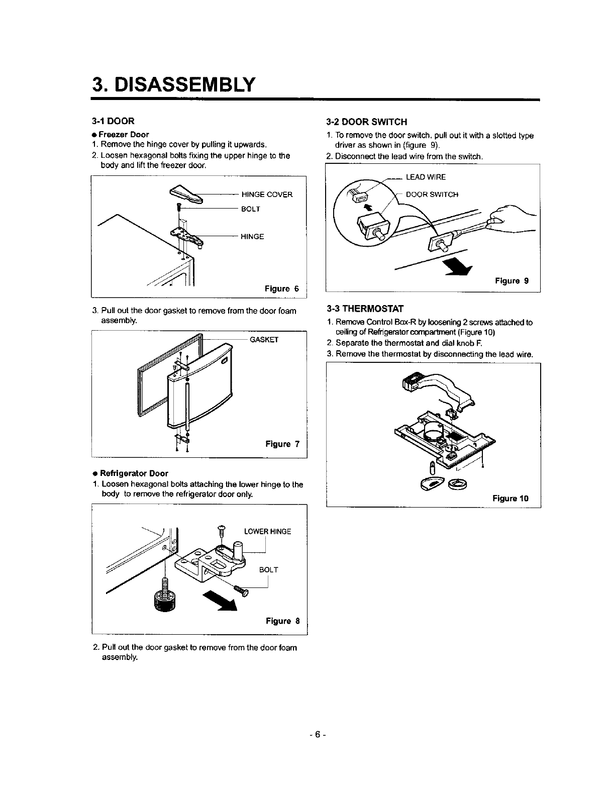
3-1 DOOR
• Freezer Door
1, Remove the hinge cover by pulling it upwards.
2. Loosen hexagonal bolts fixing the upper hinge to the
body and lift the freezer door.
HINGE COVER
BOLT
HINGE
Figure 6
3. Pull out the door gasket to remove from the door foam
assembly.
GASKET
Figure 7
•Refrigerator Door
1, Loosen hexagonal bolts attaching the lower hinge to the
body to remove the refrigerator door only.
3-2 DOOR SWITCH
1. To remove the door switch, pull out it with a slotted type
driver as shown in (figure 9).
2. Disconnect the lead wire from the switch.
LEAD WIRE
DOOR SWITCH
Figure 9
3-3 THERMOSTAT
1. Remove Control Bc_-R by loosening 2 screws attached to
ceilingof Reffigerator comparb_ent (Figure 10)
Separate the thermostat and dial knob F.
Remove the thermostat by disconnecting the lead wire.
Figure 10
<_ LOWER HINGE
BOLT
Figure 8
2. Pun out the door gasket to remove from the door foam
assembly.
-6-
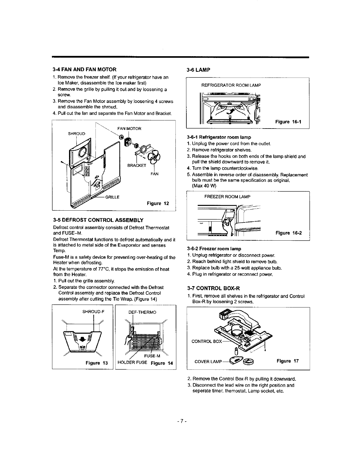
3-4 FAN AND FAN MOTOR
1. Remove the freezer shelf, (If your refrigerator have an
Ice Maker, disassemble the Ice maker first)
2. Remove the grille by pulling it out and by loosening a
screw,
3. Remove the Fan Motor assembly by loosening 4 screws
and disassemble the shroud.
4. Pull out the fan and separate the Fan Motor and Bracket.
SHROUD
Figure 12
3-5 DEFROST CONTROL ASSEMBLY
Defrost control assembly consists of Defrost Thermostat
and FUSE-M.
Defrost Thermostat functions to defrost automatically and it
is attached to metal side of the Evaporator and senses
Temp.
Fuse-M is a safety device for preventing over-heating of the
Heater when defrosting.
At the temperature of 77°C, it stops the emission of heat
from the Heater.
1. Pull out the grille assembly.
2. Separate the connector connected with the Defrost
Control assembly and replace the Defrost Control
assembly after cutting the Tie Wrap. (Figure 14)
SHROUD-F
Figure 13
DEF-THERMO
FUSE-M
HOLDERFUSE Figure 14
3-6 LAMP
REFRIGERATOR ROOM LAMP
Figure 16-1
3-6-1 Refrigerator room lamp
1. Unplug the power cord from the outlet.
2. Remove refrigerator shelves.
3. Release the hooks on both ends of the lamp shield and
pull the shield downward to remove it.
4. Turn the lamp counterclockwise.
5. Assemble in reverse order of disassembly. Replacement
bulb must be the same specification as odginaL
(Max 40 W)
FREEZER ROOM LAMP
Figure 16-2
3-6-2 Freezer room lamp
1. Unplug refrigerator or disconnect power.
2, Reach behind light shield to remove bulb.
3. Replace bulb with a 25-watt appliance bulb,
4. Plug in refrigerator or reconnect power,
3-7 CONTROL BOX-R
1. First, remove all shelves in the refrigerator and Control
Bax-R by loosening 2 screws,
CONTROL BOX-
COVER LAMP_ Figure 17
2. Remove the Control Box-R by pulling it downward.
3. Disconnect the lead wire on the right position and
seperate timer, themostat, Lamp socket, etc.
-7-
4. ADJUSTMENT
_1 COMPRESSOR
4-1-1 Role
The compressor intakes low temperature and low pressure
gas evaporated from evaporator of the refrigerator, and
condenses this gas to high temperature and high pressure
gas, and then plays delivering role to condenser.
4-1-2 Composition
The compressor includes overload protection. The PTC
starter and OLP (overload protector) are outside the
compressor. Since the compressor is manufactured to
tolerances of Imicron, and is sealed in a dust - and
moisture - free environment, use extreme caution when
repairing it.
4-%3 Note for Usage
(1) Be careful not to allow over-voltage and over-current.
(2) No Strike
If applying forcible power or strike (dropping or careless
handling), poor operation and noise may occur.
(3) Use proper electric components appropriate to the
Compressor.
(4) Note to Keep Compressor,
If Compressor gets wet in the rain and rust in the pin of
Hermetic Terminal, the result may be poor operation
and poor contact may cause.
(5) Be careful that dust, humidity, and welding flux don't
contaminate the compressor inside when replacing the
Compressor. Dust, humidity, and flux due to welding
which contaminates the cylinder may cause leskage
and noise.
4-2 PTC-STARTER
4-2-1 Composition of PTC-Starter
(1) PTC (Positive Temperature Coefficient) is a no-centact
semiconductor starting device which uses ceramic
material consisting of BaTiO3.
(2) The higher the temperature is, the higher the resistance
value. These ,features are used as starting device for
the Motor,
4-2-2 Role of PTC-Starter
(1) PTC is attached to Hermetic Compressor used for
Refrigerator, Show Case, and starting Motor,
(2) Compressor for household refrigerator applies to
single-phase induction Motor.
For normal operation of the single-phase induction
motor, in the starting operation flows in both main coil
and sub-coil. After the starting is over, the current in
subcoil is cut off. The proper features of PTC play aft
the above roles. So, PTC is used as a motor starting
device.
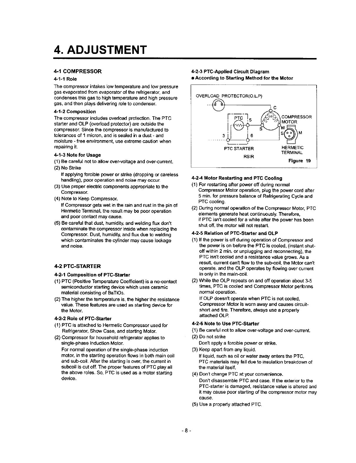
4-2°3 PTC-Applied Circuit Diagram
•According to Starting Method for the Motor
OVERLOAD PROTECTOR(O.L.P)
F- -c-q F COMPRESSOR
.....
PTC STARTER HERMETIC
TERMINAL
RSIR Figure 19
4*2*4 Motor Restarting and PTC Cooling
(1) For restarting after power off during normal
Compressor Motor operation, plug the power cord after
5rain. for pressure balance of Refrigerating Cycle and
PTC cooling.
(2) During normal operation of the Compressor Motor, PTC
elements generate heat continuously. Therefore,
if PTC iso't cooled for a while after the power has been
shut oft, the motor will not restart.
4-2-5 Relation of PTC-Starter and OLP
(1) If the power is off during operation of Compressor and
the power is on before the PTC is cooled, (instant shut-
off within 2 rain. or unplugging and reconnecting), the
PTC isn't cooled and a resistance value grows. As a
result, current can't flow to the sub-ceil, the Motor can't
operate, and the OLP operates by flowing over current
in only in the main-cofi.
(2) While the OLP repeats on and off operation about 3-5
times, PTC is cooled and Compressor Motor performs
normal operation.
If OLP doesn't operate when PTC is not cooled,
Compressor Motor is worn away and causes cimuit*
short and fire. Therefore, always use a properly
attached OLR
4-2-6 Note to Use PTC-Starter
(1) Be careful not to allow over-voltage and over-current.
(2) Do not strike
Don't apply aforcible power or strike.
(3) Keep apart from any liquid.
If liquid, such as oil or water away enters the PTC,
PTC materials may Faildue to insulation breakdown of
the materiel itself.
(4) Don't change PTC at your convenience.
Don't disassemble PTC and case. If the exterior to the
PTC-starter is damaged, resistance value is altered and
it may cause poor starting of the compressor motor may
cause.
(5) Use apropedy attached PTC.
-8-
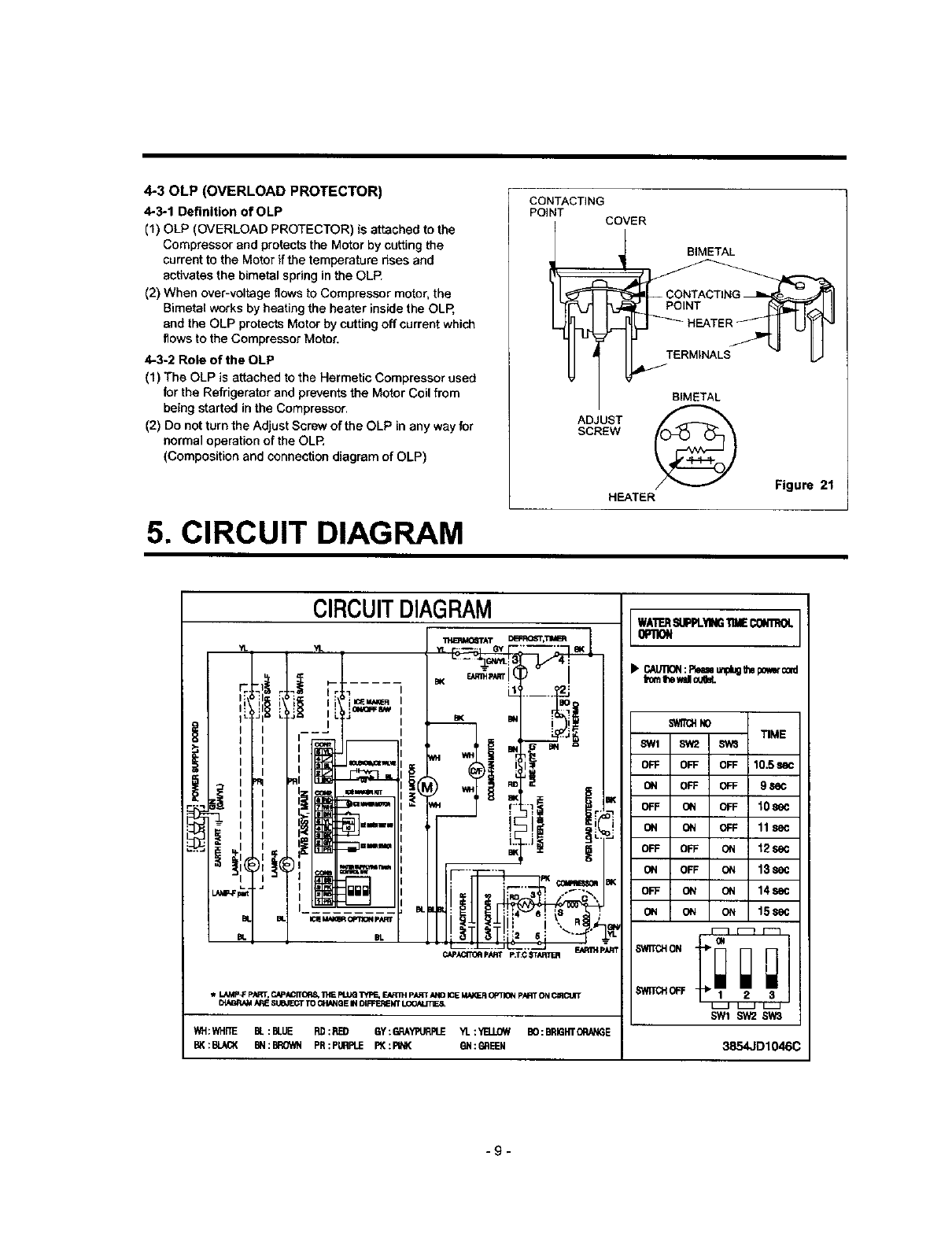
4-30LP (OVERLOAD PROTECTOR)
4-3-1 Definition of OLP
(1) OLP (OVERLOAD PROTECTOR) is attached to the
Compressor and protects the Motor by catting the
current to the Motor if the temperature rises and
activates the bimetal spring in the OLP.
(2) When over-voltage flows to Compressor motor, the
Bimetat works by heating the heater inside the OLR
and the OLP protects Motor by catting off currant which
flows to the Compressor Motor.
4-3-2 Role of the OLP
(1) The OLP is attached to the Hermetic Compressor used
for the Refrigerator and prevents the Motor Coil from
being started in the Compressor.
(2) Do not turn the Adjust Screw of the OLP in any way for
normal operation of the OLR
(Composition and connection diagram of OLP)
5. CIRCUIT DIAGRAM
CONTACTING
POINT COVER
__BIMETAL
BIMETAL
ADJUST
SCREW
Figure 21
HEATER
10.5=
9se(
lOse
11se
t2se
13se
14s_
15se
SWn_H0FF 2 3
SWI SW2SW3
3854JD1046C
-9-
6. TROUBLESHOOTING
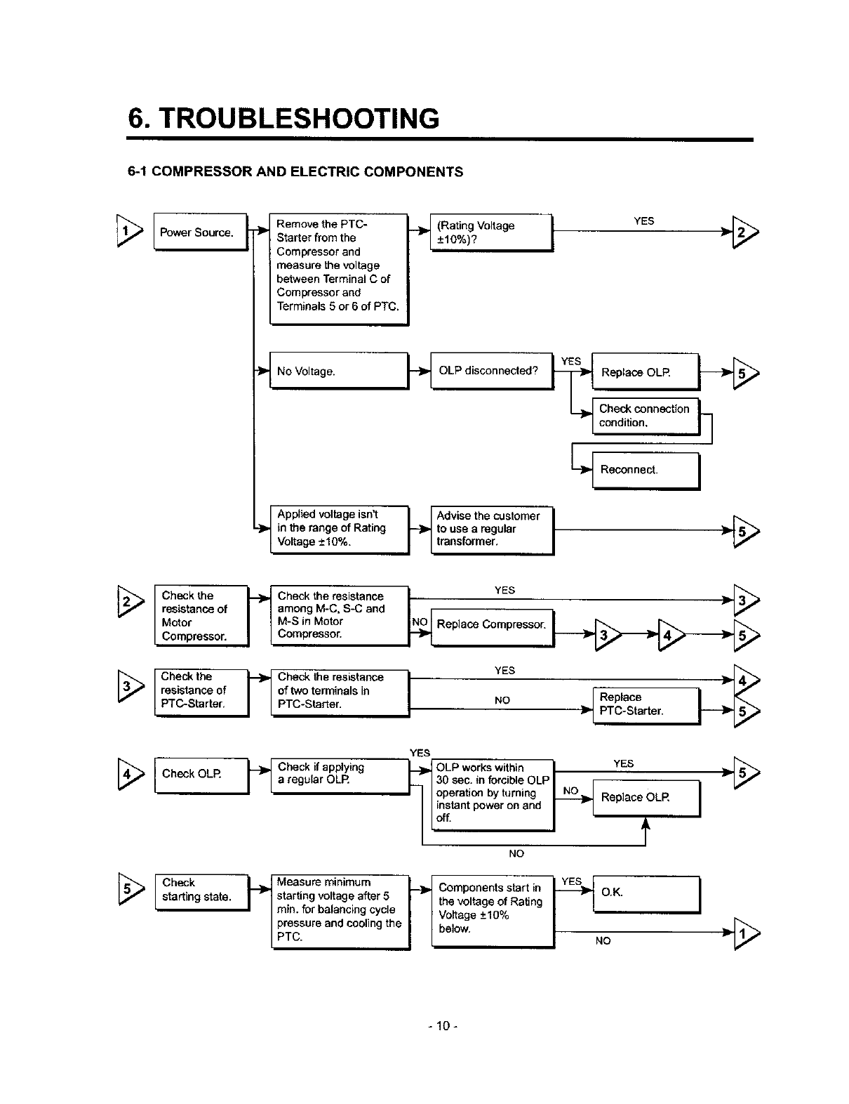
6-1 COMPRESSOR AND ELECTRIC COMPONENTS
Power Source. .._ Remove the PTC-
Starter from the
Compressor and
measure the voltage
between Terminal C of
Compressor and
Terminals 5 or 6 of PTC,
-_No Voltage.
/Applied voltage isn't
-}P,_in the range of Rating
/Voltage +-10%.
_}_ (Rating Voltage I+-10%)?
-_ OLP disconnected?
YES }l_[_
_Replace OLR
Check connection t_ 1
condition.
L-_ Reconnect. I
H Advise the customer I [_
to use aregular }_
transformer.
[_ heck the
resistance of
Motor
Compressor.
[_ Check the
resistance of
PTC-Starter,
[_ [ Check OLR
[_ [ sChartieCnkgstate.
i_ heck the resistance
among M-C, S-C and
M-S in Motor
Compressor.
--_ heck the resistance
of two terminals in
PTC-Starter.
N_O YES }__
Replace Compressor.
IYES
NO }_ Replace
PTC-Starter.
YES
_1 Check if applying I.__ OLP works within "IYES .[_
aregular OLR I-_ 130 sec. in forcible OLPI _I
II Ioperation by turning _ Replace OLR
I-'
NO
t_ Measure minimum I--_
starting voltage after 5 IrI
min. for baiencing cycle I I
pressure and cooling the _ I
PTC. I IComponentsstartin I_ o.K. I
the voltage of Rating
Voltage +_10%
below. NO }1-[_
-10-
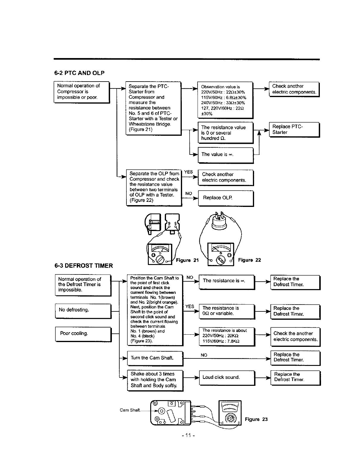
6-2 PTC AND OLP
INormal operationof
Compressor is
impossibleor poor.
6-3 DEFROST TIMER
Separate the PTC-
Sl_rter from
Compressor and
measure the
resistance between
' No. 5 and 6 of PTC-
Starter with a Tester or
Wheatstone Bridge.
(Figure 21)
Observationvalue is
220V/5OHz: 22_:_30%
115V/6OHz ;6.8_.__+30%
240V/50Hz ;33(_±30%
127, 220V/60Hz : 22_
±30%
The resistance value
is 0or several
hundred Q.
The value is _.
Check another
electric components.
Replace OLR
Separate the OLP fmm_ YES_ _
"_' Compressor and check I
the resistance value II
between two terminals I,
of OLP with a Tester. NLN0_
(Figure 22)
.._ Check another I
electric components. I
I
I
(_Figure 21_igure 22
Normal operation of
the Defrost Timer is
impossible.
No defrosting.
Poorcooling.
fl Position the Cam Shaft to
"_ the point of first click
sound and check the
current flowing between
terminals No. t(brown)
and No. 2(bright orange).
FNext, position the Cam
Shaft to the point of
second click sound and
check the current flowing
between terminals
___ No. 1 (brown) and
No. 4 (black)
(Figure 23).
- Turn the Cam Shaft.
Shake about 3 times
"-_ with holding the Cam
Shaft and Body softly.
--_ The resistance is _o.
__The resistance is
OQ or variable.
__The resistance is about
220VISOHz: 20K_
1t 5V/6OHz : 7.8K3.2
I "°
Loud click sound.
H
-I
Replace the
Defrost Timer.
Replace the I
Defrost Timer.
i
Check the another I
i
electric components. I
Replace the I
Defrost Timer.
Replace the I
Defrost Timer.
-11 -
Figure 23
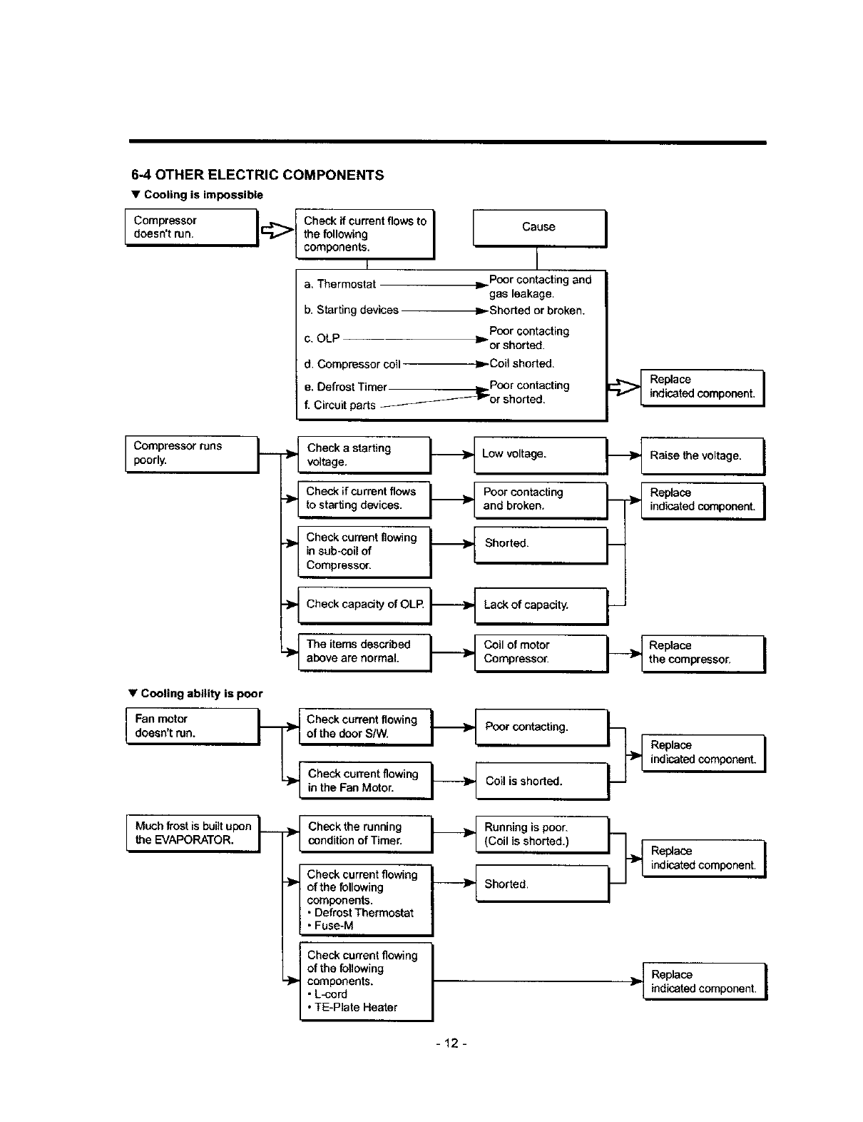
6-4 OTHER ELECTRIC COMPONENTS
•Cooling is impossible
Compressor I
doesn't ran. I:_ Check ff cuwentflowsto
the following
component.
I
a. Thermostat
b. Starting devices
Cause
I
Poor contacting and
gas leakage.
,._Shorted or broken.
Poorsenta_ing
c. OLP _orshorted.
d. Compressor coil _Coilshorted.
e. Defrost Timer _ Poor contacting
f. Circuit parts ____-_--_"or shorted.
I
_Replace
indicated component. I
JCompressor runs
poorly. _heck a starting _{ Low voltage.voltage.
.}_ Check if currant flows t._ Poor oontecting
to starting devices, and broken.
_ heckcum_nt flo_ng ___ Shorted.
in sub-coil of
Compressor.
•Cooling ability is poor
IFan motor
doesn't run.
Much frost is built upon
the EVAPORATOR. I---
Check capacity of OLR
The items described
above are normal.
Lack of capacity.
_,_ oil of motorCompressor.
i I
Check current flowing _._
of the door S/W. Poor contacting.
Check current flowing _ Coil is shorted.
in the Fan Motor. I-I
Check the running _ Running is poor.
condition of Timer. Irl (Coil is shorted.)
Check current flowing I_l
of the following _ Shorted.
components.
•Defrost Thermostat
i•Fuse-M
Check current flowing I
of the following I
components.
• L-cord
•TE-Piate Heater
Raise the voltage. I
_'-- }_ iRndiP_t6_dcemp°ne_" I
_Replece
the compressor. I
Replace I
indicated component.
Replace I
indicated component.
Replace
indicated component. I
-12-
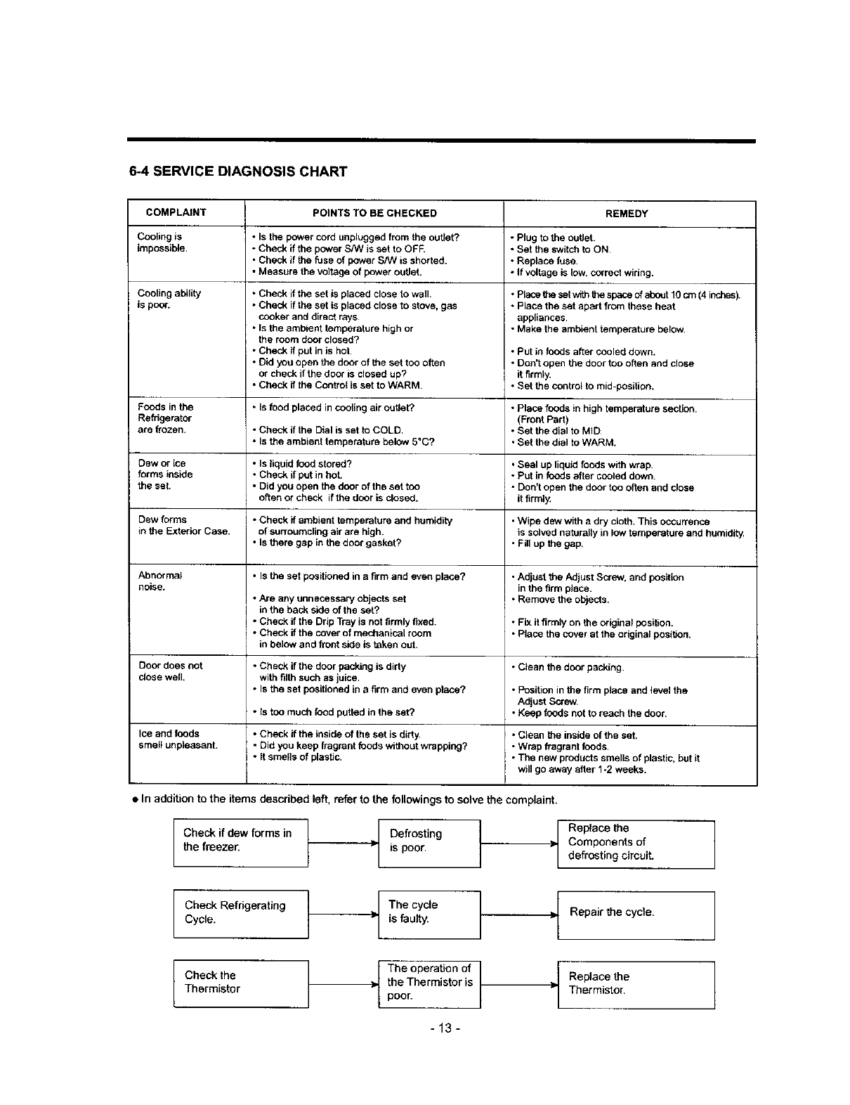
6-4 SERVICE DIAGNOSIS CHART
COMPLAINT POINTS TO BE CHECKED REMEDY
Cooling is • Is the power cord unplugged from the outlet? • Plug to the outlet.
impossible. • Check if the power Sh/V is set to OFF • Set the switch to ON
• Check if the fuse of power S/W is shorted. •Replace fuse.
• Measure the voltage of power outlet. • If voltage is low. correct wiring.
Cooling ability
is poor.
•Check if the set is placed close to wall.
• Check if the set is placed close to stove, gas
cooker and direct rays
• Is the ambient temperature high or
the room door closed?
• Check if put In is hot.
• Did you open the door of the set too often
or check if the door is closed up?
•Check if the Control is set to WARM.
• Place toe set wfih the space of abeut 10 ctn (4 inches).
• Place the set apart from these heat
appliances.
• Make the ambient temperature beidw.
• Put in ti_ds after cooled down.
•Don't open the door too often and dose
it firmly.
• Set the control to mid-position.
Foods in the • Is food placed in cooling air outlet.? • Place foods in high temperature section.
Refrigerator (Front Part)
are frozen. • Check if the Dial is set to COLD. • Set the dial to MID
•Is the ambient temperature below 5°C? •Set the dial to WARM.
Dew or ice • Is liquid food stored? • Seal up liquid foods w_th wrap.
forms inside • Check if put in hot. - Put in foods after cooled down.
the set. • Did you open the door of the set too • Don't open the door too often and close
often or check iftbe door is closed, it firml_
Dew forms *Check if ambient temperature and humidify •Wipe dew with a dry cloth, This occurrence
in the Exterior Case. of surroumding air are high. is solved naturally in low temperature and humidity.
• Is there gap in the door gasket? •Fill up the gap.
Abnormal •Is the set positioned in a firm and even place? - Adjust the Adjust Screw, and position
noise, in the firm place.
• Are any unnecessary objects set •Remove the objects.
in the back side of the set?
•Check if the Drip Tray is not firmly fixed. •Fix it firmly on the original position.
•Check if the cover of mechanical room •Place the cover at the original position.
in below and front side is taken out.
Door does not •Check if the door packing is dirty •Clean the door packing.
dose well, with filth such as juice.
• Is the set positioned in afirm and even ptace? • Position in the firm place and level the
Adjust Screw.
• Is too much food putted in the set? • Keep foods not to reach the door.
Ice and foods • Check if the inside of the set is dirty •Clean the inside of the set.
smell unpleasant. • Did you keep fragrant foods without wrapping? - Wrap fragrant foods.
• It smells of plastic. *The new products smells of plastic, but it
will go away after 1-2 weeks.
•In addition to the items described left, refer to the followings to solve the complaint.
/
Checkif dew forms in /
F
the freezer.
Defrosting
is poor.
Replace the
Components of
defrosting circuit.
Check Refrigerating t _ The cycle
Cycle. is faulty.
Check the
Thermistor
]= Repair the cycle.
The operation of
the Thermistor is
poor.
Replace the
Thermistor,
-13-

6-5REFRIGERATINGCYCLE
•Troubleshooting Chart
STATE OF STATE OF THE TEMPERATURE
CAUSE THE SET EVAPORATOR OF THE REMARKS
COMPRESSOR
PARTIAL Freezer Low flowing sound of A little higher -Refrigerant level is low due
LEAKAGE compartment and Refrigerant is heard and than ambient to a leak.
Refrigerator don't frost forms in inlet only temperature. •Normal cooling is possible
mr- cool normally, when injecting of Refrigerant
>the regular amount.
_m WHOLE Freezer Flowing sound of refrigerant Equal to ambient • No discharging of Refrigerant.
LEAKAGE compartment and is not heard and frost isn't temperature. •Normal cooling is possible
Refrigerator don't formed, when injecting of Refrigerant
cool normally, the regular amount.
PARTIAL Freeze Flowing sound of refrigerant A little higher •Normal discharging of
CLOG compartment and is heard and frost forms than ambient refrigerant,
Refrigerator don't in inlet only. temperature, o The capillary tube is faulty.
C>
m cool normally.
WHOLE Freezer Flowing sound of refrigerant Equal to ambient • Normal discharging of
CLOG compartment and is not heard and frost isn't temperature. Refrigerant.
u_
•_ Refrigeratordon'tcool. formed.
MOISTURE Cooling operation Flowing sound of refrigerant Lower than •Cooling operation restarts
CLOG stops periodically, is not heard and frost melts, ambient when heating the inlet of
temperature capillary tube.
O COMP- Freezer end Low flowing sound of A little higher •Low pressure at high side
O m RESSION Refrigerator refrigerant is heard and ambient of compressor due to low
-o"n
:o m don't cool. frost forms in inlet only. temperature, refrigerant level.
mO
u)--I
_ NO COMP- No compressing Flowing sound of refrigerant Equal to ambient • No pressure of high pressure
O m RESSION operation, is not heard and no frost, temperature, part in the compressor.
t
•Leakage Detection
•Observe dischargingpointof refdgerant which may be in the oil dischargingpart in the compressorand hole of evaporator,
[
Check if compressor YES ICheck if frost
runs or not. J'l forms or not in
Evaporator.
J
iFr°st f°rmed n°rmalli Normal areount
Moisture Clog
_- Check if oil
No frost leaks or not.
or forms
in inlet only |
Observe the discharged
amount of Refrigerant.
_, No or much amount
Faulty Inject refrigerant to compressor
Compressor, and check cooling operation. I
Check Compressor IClogged by dust. 1
Frost formed normally
YES
r
>! Gas leakage. I
(Check the leakage point)
-14-
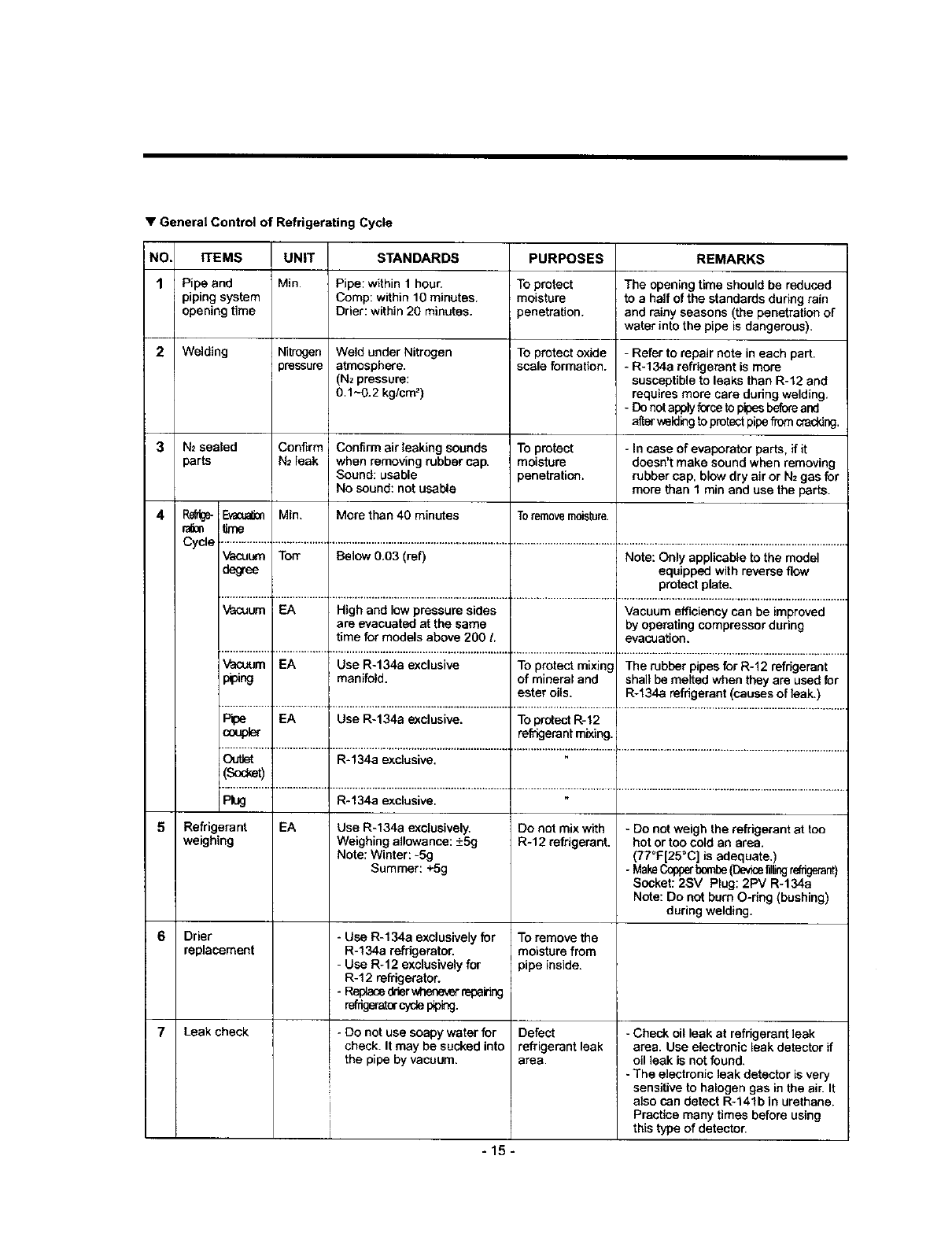
•General Control of Refrigerating Cycle
NO.
1
4
5
6
7
EEMS
Pipe and
piping system
opening time
Welding
N_sealed
parts
RefUge-_
r'a_0n time
UNIT
Min.
STANDARDS
Pipe: within 1hour.
Comp: within 10 minutes.
Drier: within 20 minutes.
Nitrogen Weld under Nitrogen
)ressure atmosphere.
(Nz pressure:
0.1-0.2 kg/cm z)
Confirm Confirm air leaking sounds
N2 leak when removing rubber cap.
Sound: usable
No sound: not usable
Min. More than 40 min_es
PURPOSES
TOprotect
moisture
penetration.
To protect oxide
scale formation.
To pre_ct
moi_ure
penetmtion+
Toremovemoisture.
REMARKS
The opening time should be reduced
to ahalf of the standards during rain
and rainy seasons (the penetration of
water into the pipe is dangerous).
- Refer to repair note in each part.
- R+134a refrigerant is more
susceptible to leaks than R-12 and
requires more care during welding,
- Do not apply ferce to pipes before and
a_erwelding toprotect pipe from cracking.
- in case of evaporator parts, if it
doesn't make sound when removing
rubber cap, blow dry air or N2 gas for
more than 1 rain and use the parts.
Cycle ................._..................._...............................................................÷...................................._................................................................................
Vacul._m Tort Below 0.03 (ref) Note: Only applicable to the model
deg'ee equipped with reverse flow
protect plate.
................. *_.................. 1............................................................... ÷.................................... i ................................................................................
Vacuum =EA High and low pressure sides Vacuum efficiency can be improved
are evacuated at the saree by operating compressor during
time for models above 200 Levacuation.
Vacuum EA Use R-134a exclusive To protect mixing The rubber pipes for R-12 refrkJerant
p_oing manifold, of mineral and shall be melted when they are used for
ester oils. R-134a refrigerant (causes of leak.)
................. _ ................. 1............................................................... +.................................... + ..............................................................................
Pipe EA Use R-134a exclusive. To protect R-12
coupler refrigerant mixing.
................. i................... 1............................................................... ÷.................................... _................................................................................
Ou*Jet R-134a exclusive.
(Sod_et)
Plug R*134a exclusive.
Refrigerant
weighing
Drier
replacement
Leak check
EA Use R-134a exclusively.
Weighing allowance: +5g
Note: Winter: -5g
Summer: +5g
-Use R-134a exclusively for
R-134a refdgeratoc
- Usa R-12 exclusivelyfor
R-12 refrigerator.
-Replacedrierwheneverrepaiing
refrigeratorcyclepiping.
-Do not use soapy water for
i check. It may be sucked into
the pipe by vacuum.
I
Do not mix with
R+I2 refrigerant,
To remove the
moisture from
pipe inside,
Defect
refrigerant leak
area.
-Donot weigh the refrigerant at too
hot or too cold an area.
(77°F[25=C] Js adequate.)
- MakeCopperbombe(Devicefillingrefrigerant)
Socket: 2SV Plug: 2PV R-134a
Note: Do not bum O-dng (bushing)
during welding.
-Check oil leak at refrigerant leak
Iarea. Use electronic leak detector if
oil leak is not found.
-The electronic leak detector is very
sensitive to halogen gas in the air. It
also sen detect R-141b in urethane.
Practice many times before using
this type of detector.
I
-15-
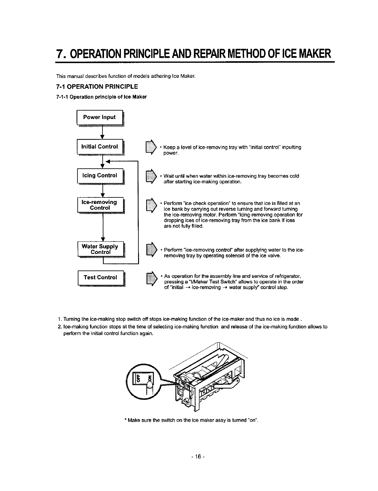
7. OPERATIONPRINCIPLEANDREPAIRMETHODOFICEMAKER
This manuel describes function of models adhering Ice Maker.
7-1 OPERATION PRINCIPLE
7-1-1 Operation principle of Ice Maker
Icing Control t
--T-
tContr._....__water Supply _
•Keep a level of ice-removing tray with "initial control" inputting
power.
• Wait until when water within ice-removing tray becomes cold
after starting ice-making operation.
.erform "ice check operation" to ensure that ice is tilled at an
ice bank by carrying out reverse turning and forward tumiog
the ice-removing motor. Perform =icing-removing operation for
dropping ices of ice-removing tray from the ice bank If ices
are not fully tilled.
•Perform "ice-removing control" after supplying water to the ice-
removing tray by operating solenoid of the ice valve.
•As operation for the assembty line and service of refdgerator,
pressing a "l/Maker Test Switch" allows to operate in the order
of =initial -_ ice-removing --_ water supply" control step.
1. Turning the ice-making stop switch off stops ice-making function of the ice-maker and thus no ice is made.
2. Ice-making function stops at the time of selecting ice-making function and release of the ice-making function allows to
perform the initial control function again.
*Make sure the switch on the ice maker assy is turned "on".
-16-
7-2 Function of Ice maker
7-2-1 Initial control function
1. The level of the ice-removing tray (ice-removing container) after completing the MICOM initialization in the initial POWER
ON,returning to elactdcity failure and turning-off of ice-making stop switches. Namely, detection lever operates up and down.
2. The level of ice-removing container is detected with high /low output signal of hall sensor.
In another words, operation is performed in order to keep a level by operating ice-removing motor so that high or low volt-
age could be applied in the MICOM PIN.
3. No signal change of hall sensors until a minute after operating the ice-removing motor should be considered as failure. In
this case, stop the automatic ice-remover and then reset the ice-maker initialization if considered as normal after perform-
ing continuous check in a cycle of an hour.
4. Keeping of the ice-remeving tray (ice-removing container) should be considered initial control is completed.
7-2-2 Water supply control function
1. Supply water into the ice-removing tray by operating the ice solenoid placed at the machine room of refrigerator using the
time check function if considered as the level is kept after performing a horizontal operation of the ice-making tray after
the ice-removing control (normal ice-rameving control, ice-removing control of test function) is completed.
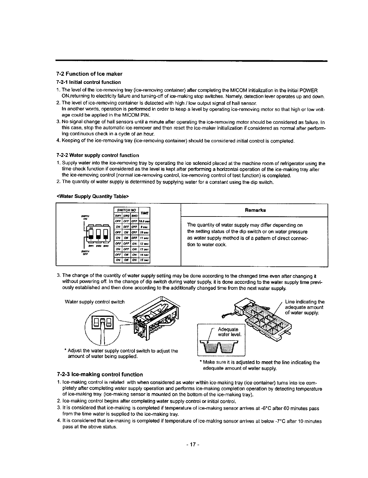
2. The quantity of water supply is determined by supplying water for a constant using the dip switch.
<Water Supply Quantity Table>
iSWITCH NO TIME
:t;Wl $W2 Sy,_*
iOFF OFF OFF _5_
Io_ ___ o_=_9=,,=
_FF O_t OFF 10_'_
_F OFF f21_
Rema_s
The quantity of water supply may differ depending on
the setting status of the dip switch or on water pressure
as water supply method is of a pattern of direct connac-
tion to water cock.
3. The change of the quantity of water supply setting may be done according to the changed time even after changing it
without powering off. In the change of dip switch during water supply, it is done according to the water supply time previ-
ously established and then done according to the additionally changed time from the next water supply.
Water supply control switch Line indicating the
adequate amount
of water supply.
* Adjust the water supply control switch to adjustthe
amount of water being supplied.
L!Adequate
waterlevel.
*Make sure it is adjusted to meet the line indicating the
adequate amount of water supply.
7-2-3 Ice-making control function
1. Ico-making control is related with when considered as water within ice-making tray (ice container) turns into ice com-
pletely after completing water supply operation and performs ice-making completion operation by detecting temperature
of ice-making tray. (ice-making sensor is mounted on the bottom of the ice-making tray).
2. fae-making control begins after completing water supply control or initial control.
3. It is considered that ice-making is completed if temperature of ice-making sensor arrives at -6°C after 60 minutes pass
from the time water is supplied to the ice-making tray.
4. It is considered that ice-making is completed if temperature of ice-making sensor arrives at below -7°C after 10 minutes
pass at the above status.
-17-
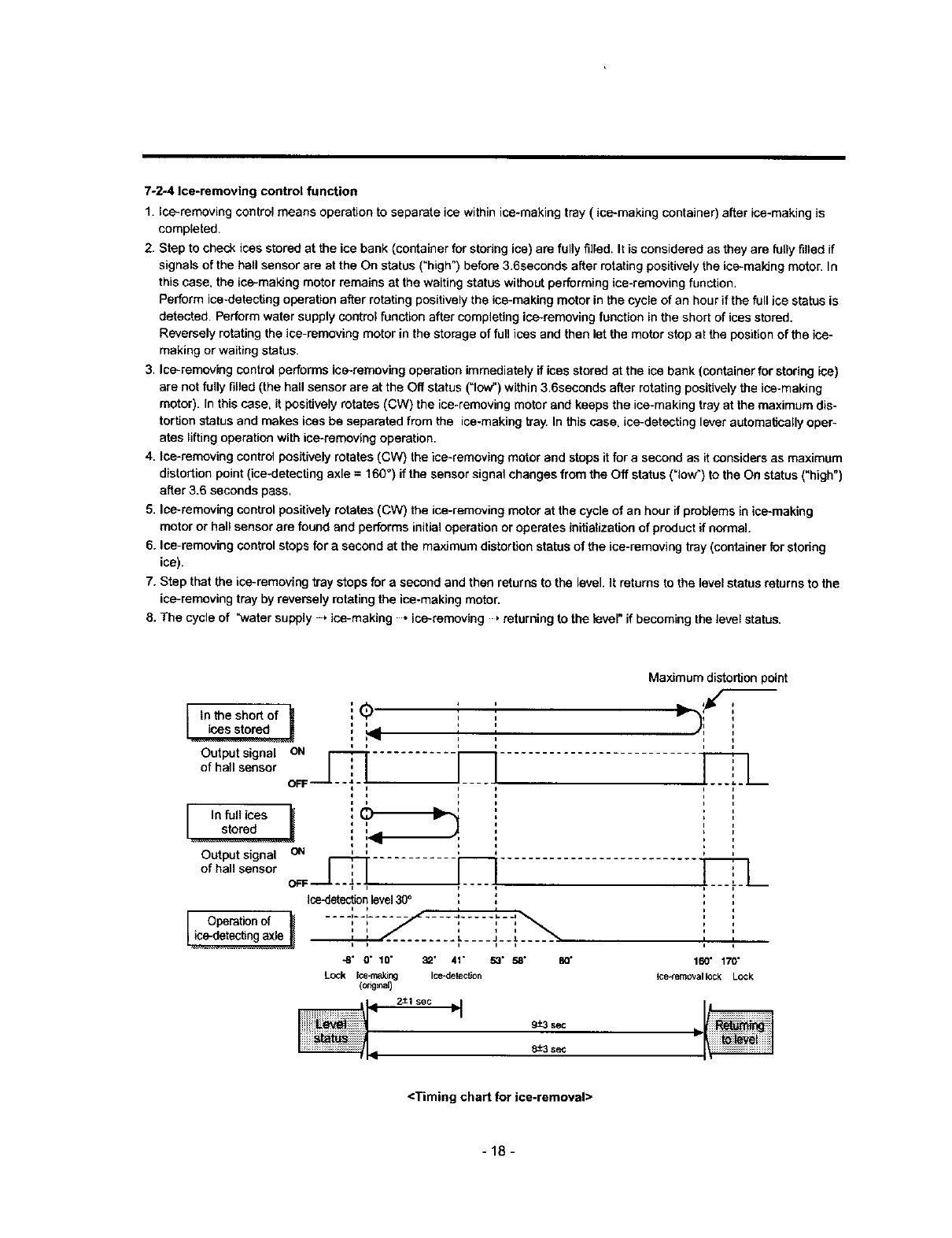
7-2-4 Ice-removing control function
1. Ice-removing control means operation to separate ice within ice-making tray (ice-making container) after ice-making is
completed.
2. Step to check ices stored at the ice bank (container for storing ice) are fully filled. It is considered as they are tully filled if
signals of the hall sensor are at the On status ("high") before 3.6seconds after rotating positively the ice-making motor. In
this case, the ice-making motor remains at the waiting status without performing ice-removing function.
Perform ice-detacfing operation after rotating positively the ica-making motor in the cycle of an hour if the full ice status is
detected Perform water supply control function after completing ice-removing function in the short of ices stored.
Reversely rotating the ice-removing motor in the storage of full ices and then let the motor stop at the position of the ice-
making or waiting status.
3. Ice-removing control performs ica-removing operation immediately if ices stored at the ice bank (container for storing ice)
are not fully filled (the hall sensor are at the Off status ("low") within 3.6seconds after rotating positively the ice-making
motor). In this case, it positively rotates (CW) the ice-removing motor and keeps the ice-making tray at the maximum dis-
tortion status and makes ices be separated from the ice-making tray. In this case. ice-detecting lever automatically oper-
ates lifting operation with ice-removing operation.
4. ice-removing control positively rotates (CW) the ice-removing motor and stops it for a second as it considers as maximum
distortion point (ica-detecting axle = 160 °) if the sensor signal changes from the Off status (=low")to the On status ("high")
after 3.6 seconds pass.
5. Ice-removing control positively rotates (CW) the ice-removing motor at the cycle of an hour if problems in ice-making
motor or hall sensor are found and performs initial operation or operates initialization of product if normal.
6. Ice-removing control stops for a second at the maximum distortion status of the ice-removing tray (container for stodng
ice).
7. Step that the ice-removing tray stops for asecond and then returns to the level. It returns to the level status returns to the
ic.e-removing tray by reversely rotating the ice-making motor.
8. The cycle of "water supply -* ice-making • ice-removing ,returning to the lever if becoming the level status.
Maximum distortion point
Itn the short of _ ', '' • ;
ii
p______ ,: , :,
ia
stor.%___]
Output signal ON_ ._ ............................
of hall sensor
OFF I I
Ice-detectionlevel300
i i , ii
.... L.... J-.J.
i i iii
Operation of
-8" O" 10" 32' 41" 53" 50" 80" 160" 170"
LOCk loe-ma_ng loe-detec_on loe_emovallockLock
<Timing chart for ice-removal>
-18-
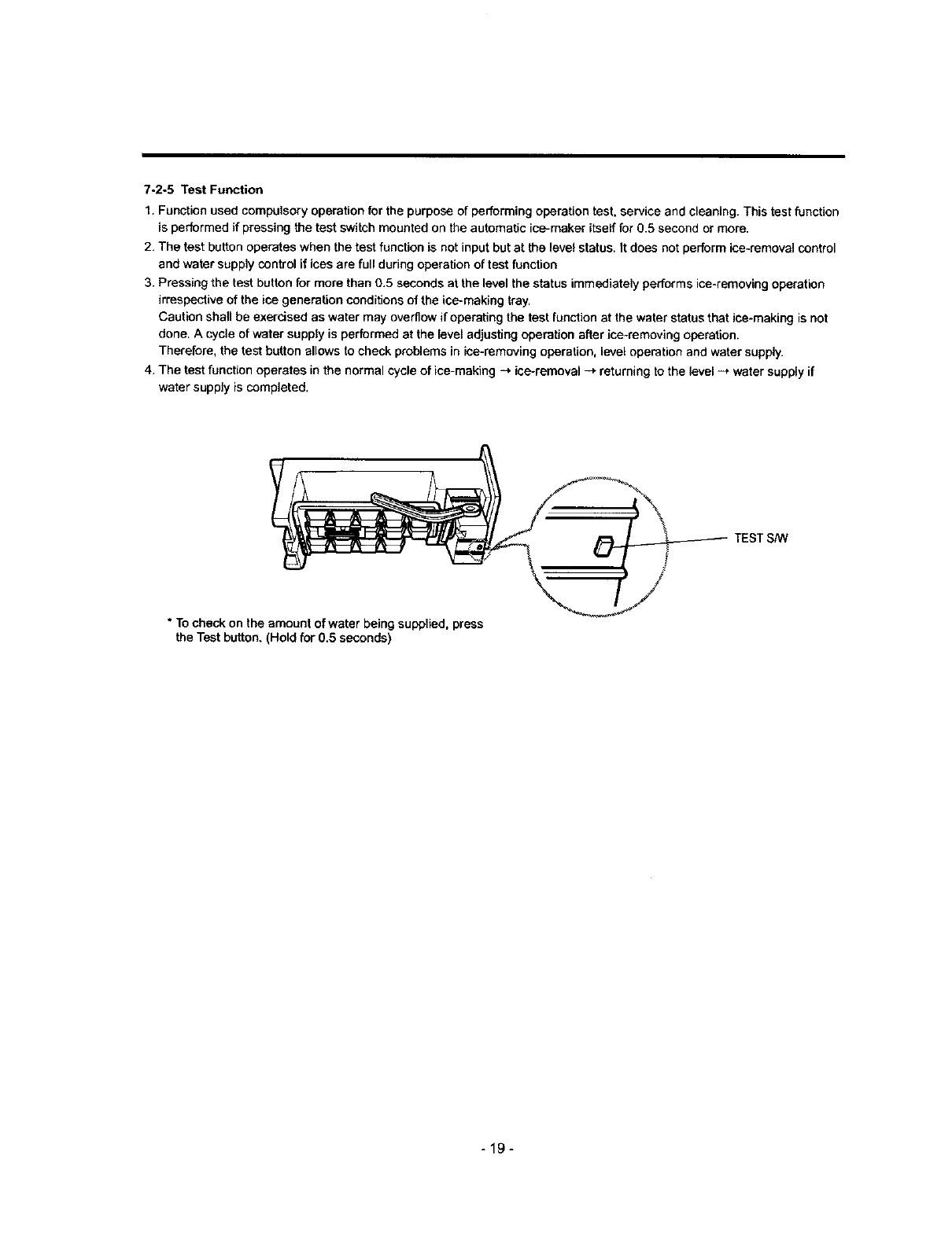
7-2-5 Test Function
1. Function used compulsory operation for the purpose of performing operation test. service and cleaning. This test function
is performed if pressing the test switch mounted on the automatic ice-maker itself for 0.5 second or more.
2. The test button operates when the test function is not input but at the level status. It does not perform ice-removal control
and water supply control if ices are full during operation of test function
3. Pressing the test button for more than 0.5 seconds at the level the status immediately performs ice-removing operation
irrespective of the ice generation conditions of the ice-making tray.
Caution shall be exercised as water may overflow if operating the test function at the water status that ice-making is not
done. A cycle of water supply is performed at the level adjusting operation after ice-removing operation.
Therefore, the test button allows to check problems in ice-removing operation, level operation and water supply.
4. The test function operates in the normal cycle of ice-making -_ ice-removal _' returning to the level --_ water supply if
water supply is completed,
* To check on the amount of water being supplied, press
the Test button, (Hold for 0.5 seconds)
-19-
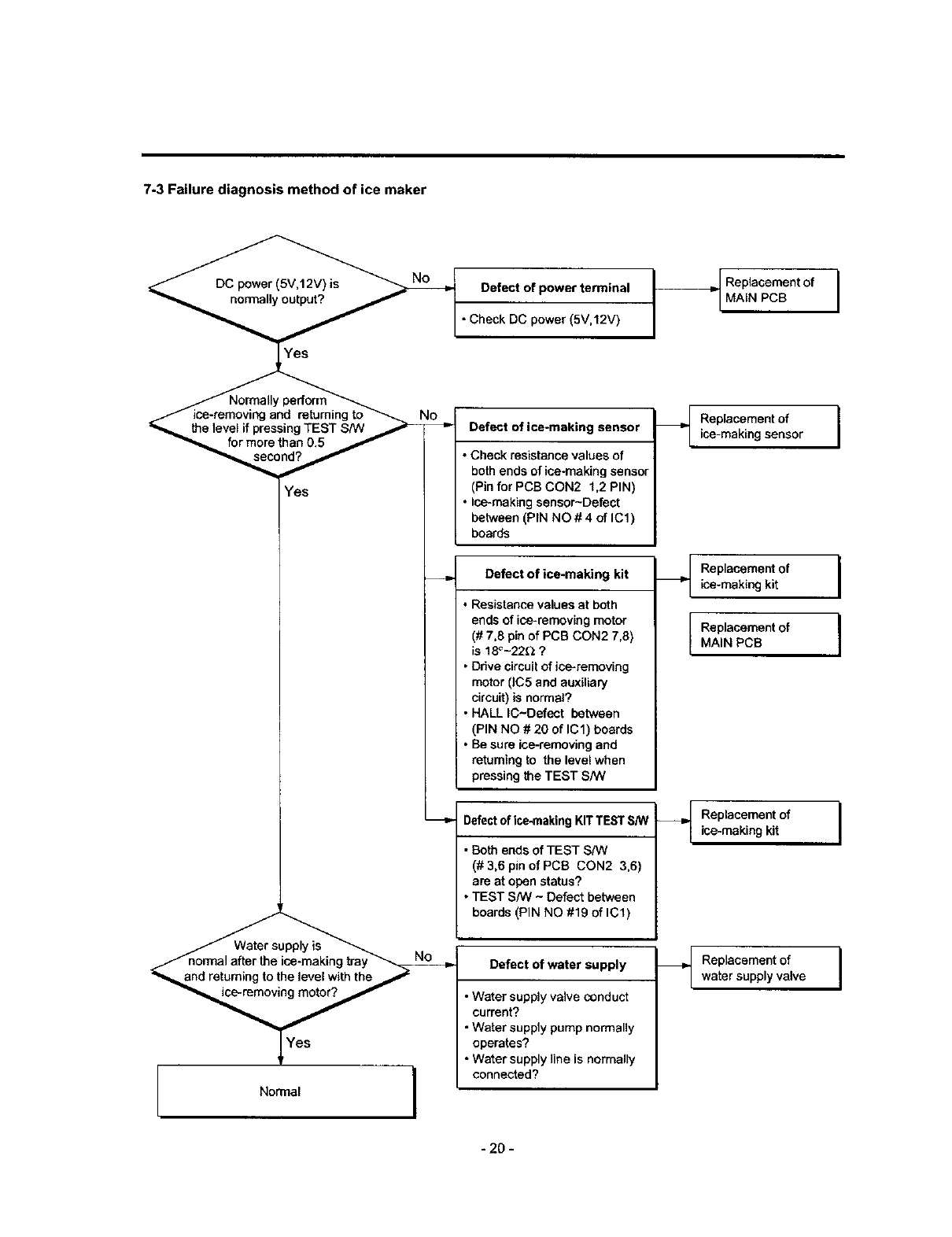
7-3 Failure diagnosis method of ice maker
Yes
r
_"'_ormal after the ice-'malting tray_
"_nd returning to the level with the/
Normal l
I [
Defect of power terminal I
• Check DC power (5V,12V)
Defect of ice-maklng sensor
•Check resistance values of
both ends of ice-making sensor
(Pin for PCB CON2 1,2 PIN)
•Ice-making sensor-Defect
between (PIN NO # 4 of IC1)
boards
Defect of ice-making kit
Resistance values at both
ends of ice-removing motor
(# 7,8 pin of PCB CON2 7,8)
is 18_-22_ ?
Ddve circuit of ice-removing
motor 0C5 and auxiliary
circuit) is normal?
HALL IC-Defect between
(PIN NO # 20 of IC1) boards
Be sure ice-removing and
returning to the level when
pressing the TEST S/W
Defect of ice-making KIT TEST S/W
• Both ends of TEST SP,_/
(# 3,6 pin of PCB CON2 3,6)
are at open status?
• TEST S/W - Defect between
boards (PIN NO #19 of IC1)
Defect of water supply
• Water supply valve conduct
current?
•Water supply pump normally
operates?
• Water supply line is normally
connected?
Replacement of
MAiN PCB I
Replacement of I
ice-making sensor
Replacement of
ice-making kit
Replacementof
MAIN PCB
I
I
Replacement of Iice-making kit
Replacementof I
watersupplyvalve
-20 -
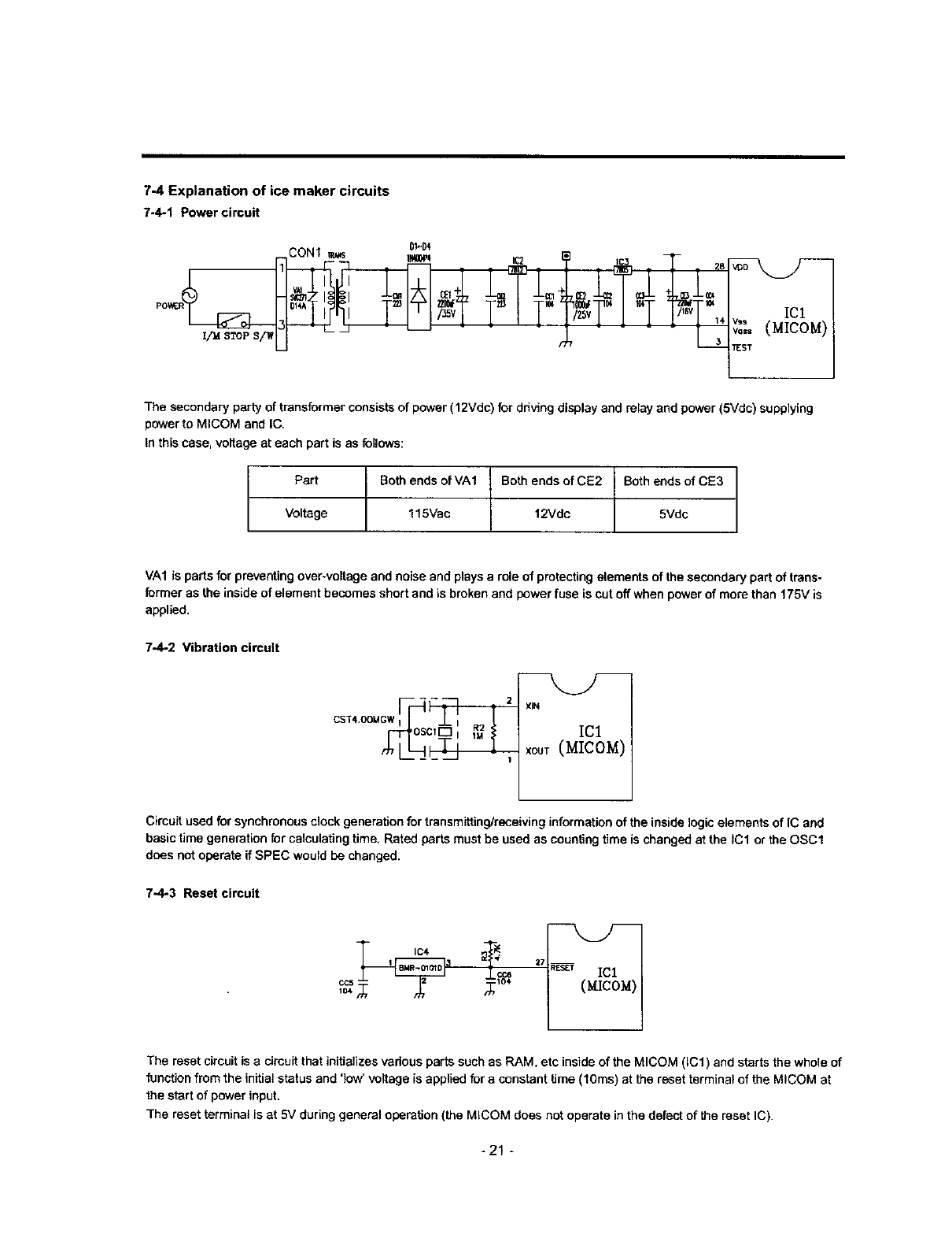
7-4 Explanation of ice maker circuits
7-4-1 Power circuit
CONI m_ I1_
ICl
_o._°°(M[COM)
TEST
The secondary party of transformer consists of power (12Vdc) for driving display and relay and power (5Vdc) supplying
power to MICOM and IC.
In this case, voltage at each part is as follows:
/
Part Both ends of VA1 |BothendsofCE2 Both ends of CE3
Voltage 115Vac "[ 12Vdc 5Vdc
VA1 is parts for preventing over-voltage and noise and plays a role of protecting elements of the secondary part of trans-
former as the inside of element becomes short and is broken and power fuse is cut off when power of more than 175V is
applied.
7-4-2 Vibration circuit
XlN
IC1
xc_T(MICOM)
Circuit used for synchronous clock generation for transmitting/receiving information of the inside logic elements of IC and
basic time generation for calculating time. Rated parts must be used as counting time is changed at the IC1 or the OSC1
does not operate if SPEC would be changed.
7-4-3 Reset circuit
The reset circuit is acimult that initializes vadous parts such as RAM, etc inside of the MICOM (ICl) and starts the whole of
function from the initial status and 'low' voltage is applied for a constant time (10ms) at the reset terminal of the MICOM at
the start of power input.
The reset terminal is at 5V during general operation (the MICOM does not operate in the defect of the reset IC).
-21 -
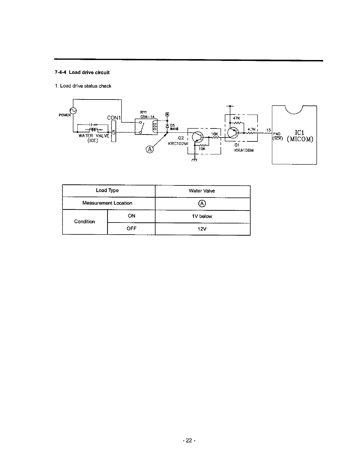
7-4-4 Load drive circuit
1. Load drive status check
D5 I
WAT RVALVEN
(ICE) U (_// I u Ill.oK --- -_
KRCIO2MI I _A_ O_
IC1
_ (MICOM)
Load Type Water Valve
Measurement Location (_)
ON I V below
Condition
OFF 12V
- 22 -
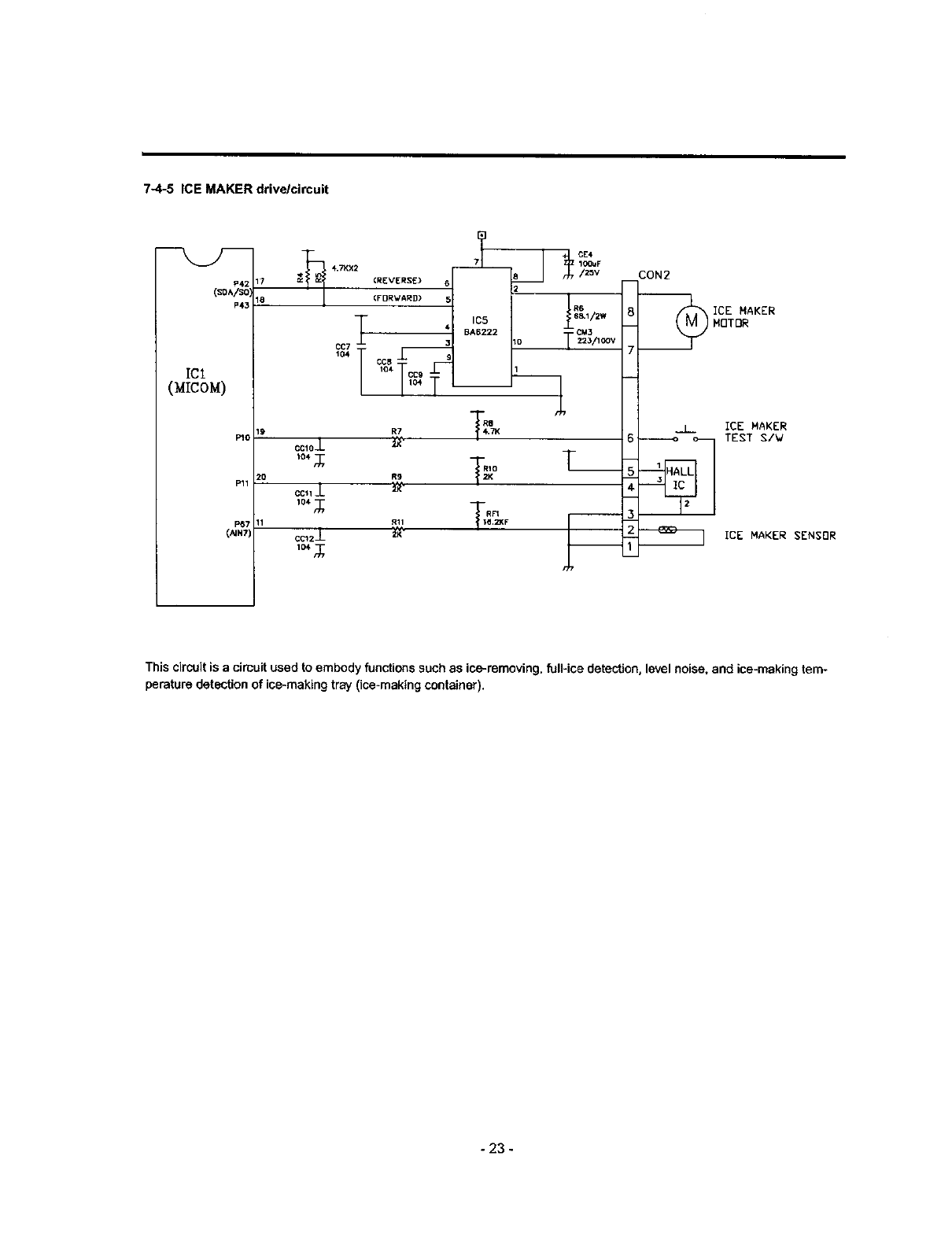
7-4-5 ICE MAKER drive/circuit
P42
(so^Iso
P43
ICI
(MICOM)
_o
P11
_7
(,4_7',
17
18
19
2O
CCLOJ-
lo4
ccllJ.
104 ,_
cc)2J_
io,,_
7 IOOUF
4.7KX2 (REVERSE) 8 2/zov CON2
(FORWARD) 5
This circuit is a circuit used to embody functions such as ice-removing, full-ice detection, level noise, and ice-making tem-
perature detection of ice-making tray (ice-making container).
- 23 -
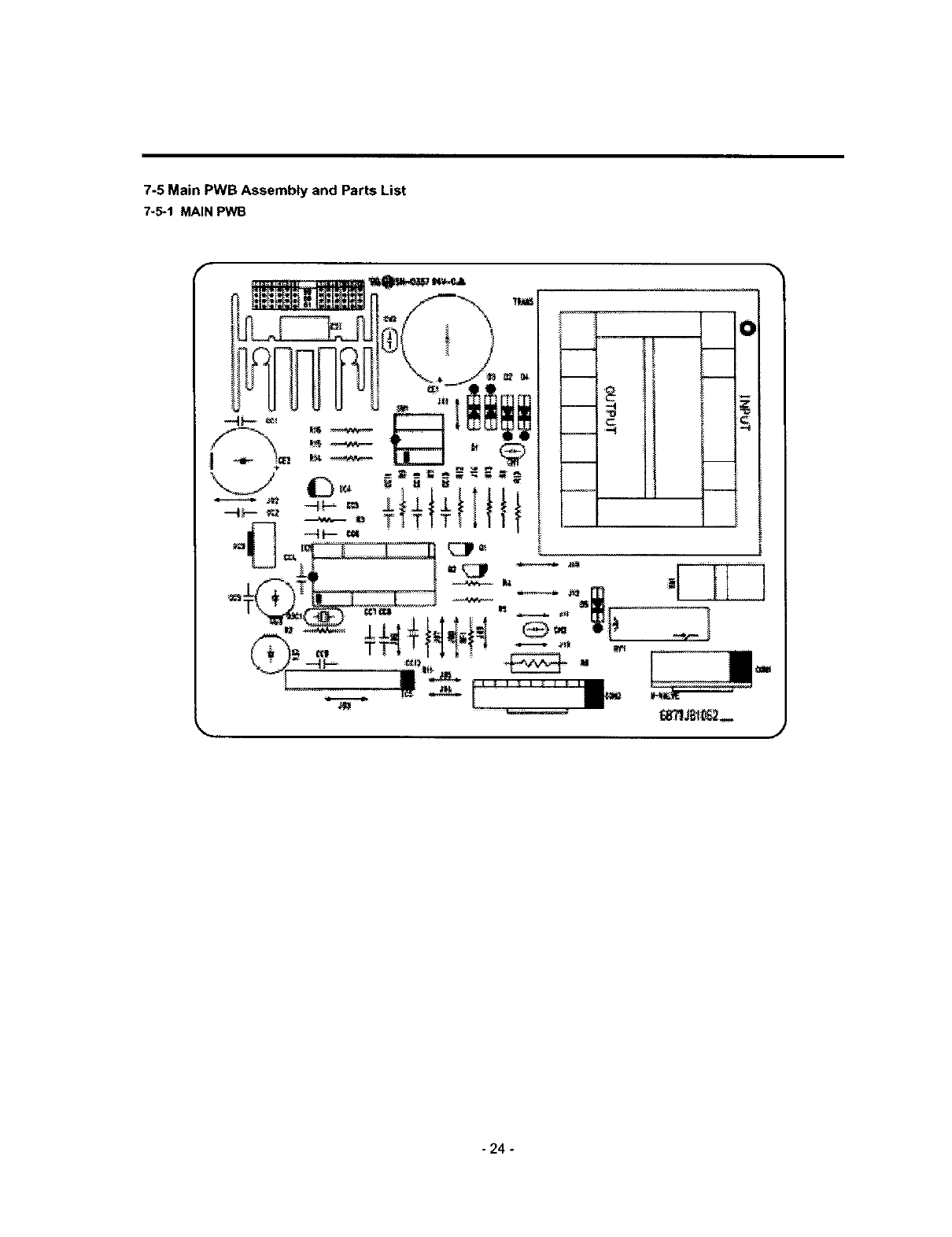
7-5 Main PWB Assembly and Parts List
7-5-1 MAIN PWB
- 24 -
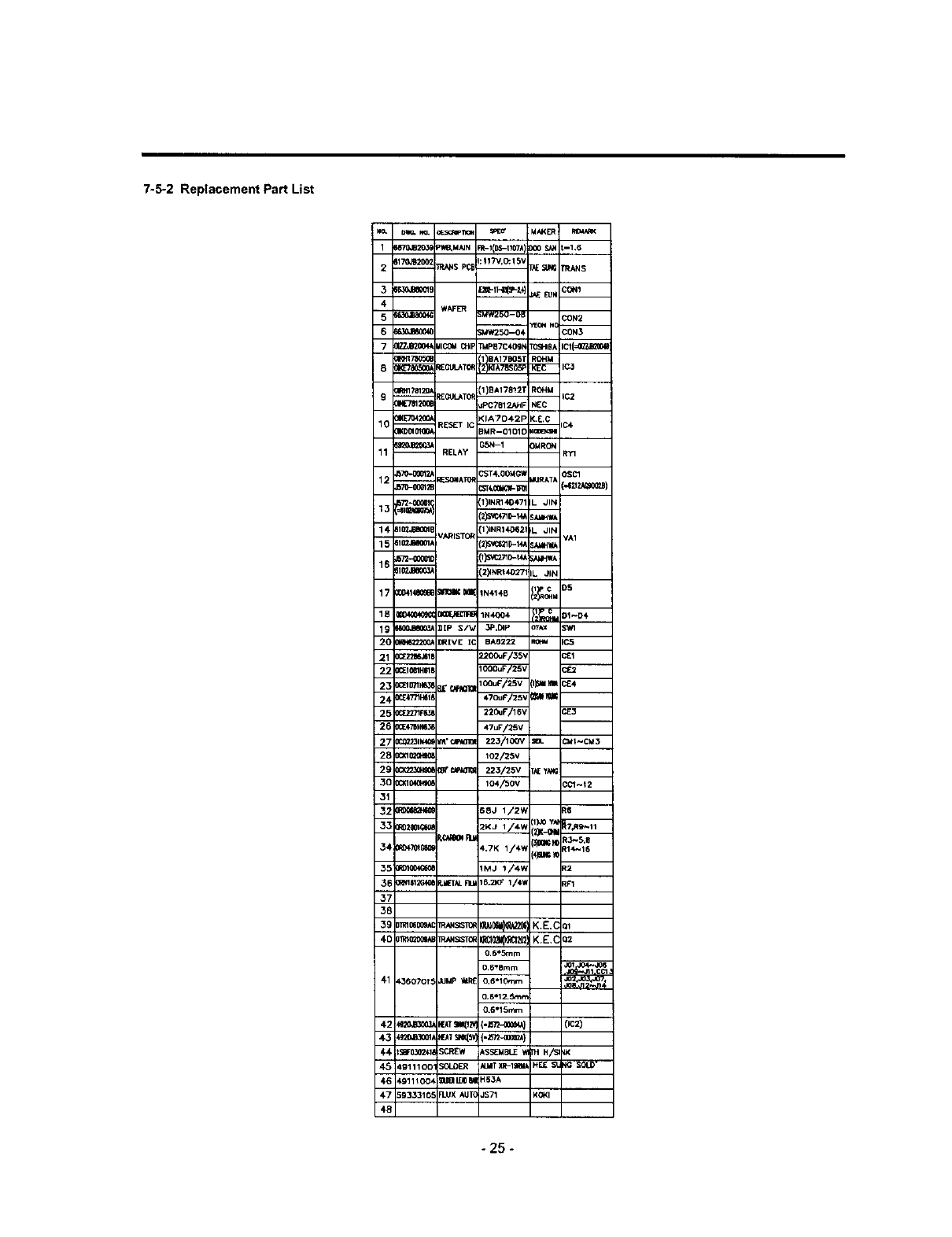
7-5-2 Replacement Part List
No. D_ _o" c_5¢m_ SPl_f M_ER _MA_<
1_170,B20_ P_*MNN FR-I(DS-t!07k))00 S_ :-1.6
-- j_:117V,C_15V
25170JB200:TRANSPC1-- r._ SI_ PRANS
4 WAFER
5_;MW250--OB CON2
6_JBSOON ;MW250-04 CON3
7_ UlCOM _1 _P87C409N rO_PIBA ICI(=O_JB2_
--_IRH17B12_,EGt3__TO1)BA17812T ROHM iC2
9m =PC7812J_F NEC
0_E70420_ <IATO42P _.E.C
10 _ _ESET IC _MR--OIO1D (m C4
E_ =35N--1 3MRON
11 -- RELAY RY1
34
12 --_70"0001_ _ONATOR --"ST4"OOM_=ORATA OSC1
17Z'-OOPBI t)INR140471 L JIN
2)S_C4710-14_Sid4qWk
14- 610'J*JBS0_I 11_NR140521L .JIN
-- IARISTOR VA1
15 610_JB_61, 2)5"V_S21_-14_SAMHWA
16-- 610_1B800_ 12_NRI402-/' IL JIN
IC
17 om_l_ceml moll,;m[ IN4148 II_oqM D5
tly c
18 0[04_04_ _1N4004 r2"_+iu DI_D4
19 _ lIP S/_ 3P.DIp o_'_x
2_ _ _R[VE IC BA6222 R_ IC5
21 o_z_6a_t _!200uF/35_ c_1
22 0_1_1H_1_ _
24 0_.47711_t8 470uF125'_ [;_Jl_ --
2_ 0(:_271F6,_ 22_F/16V _E3
26 0_476_1_ 47uF/25V
2_ 0C_211_ _'r.wa_ 223/100V SBL CMI_CM3
28 o_q_¢mo_ _o2/25v
26 _g_'r.tF_al_ 223/25V T_ yN._
3C 0G_104{1_0_ 104/50V CC1_t2
32 _S8J 1/2vt R6
F_IQO_ IMJ 1/4V_ R2
F_1612G4{_d_TALFILM16.2KF1/4_ RF1
3E
3e
3;
3e
O.6*Srnm
0.6_Smm _d01.,_ CC1
41 L36070f 5 _MP "_tREO,6*lOmm
0.6"15mm
d-4 $8F0302/,18SCR£W _SS_MBL,E TH H/S _K
45 t9111001 SOLOE_ N_4TXR-I_ HEE _klG SOLD"
_.6 _9111004 klm_ HS_A
4-7 _93331G5 _LttXAUT_ JS71 KQ(I
48
- 25 -

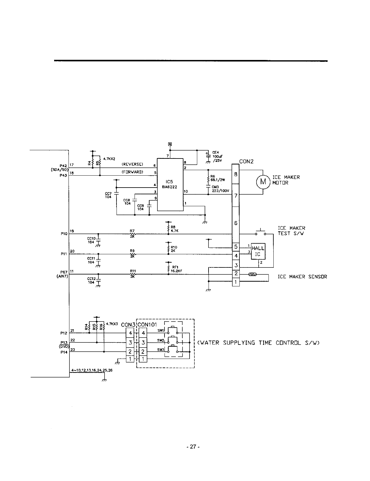
7-6 PWB DIAGRAM
, CON1F_n_s 'K_4 IC2. ? - _ - T - "
;,kgllJ,I Xl_ lo+LoLT2 Llo
[L ,_ .... L
GSN-1A 47K
--'--'--4 D5
I/1°1 T I_l'm F _ IF',,, _, I 4.TKm 15
WATER VALVE L_ I o "; :02 !/'OKI I
(ICE) I
KRCIO2MI I n_-
i
1 104 3CC6
lcoC5 2 ,_104
V_
Voss
TEST
XIN
XOUT
RESET
-26 -
P42
(_A/SOI
P_
PIO
Pll
P67
(AIN7)
17
18
P12
P14
20
CCIO*-_
104
CCll _-
I04- r_
CCt 2-I_
104 n_
(REVERSE) 6
(FBRVARD) 5
IC5
BA6222
CC8
104 CC9
R8R7 .7K
RIOR9 K
RF1Rll 6.2.KF
)OOuF
/2_v
2
68.1/2W
CM3
10 i223/100V
CON2
8
7
6
3
Z
ICE MAKER
MOTOR
ICE MAKER
TEST S/W
ICE MAKER SENSOR
21
22
23
4~10,12r 13,16,24_C,26
CON101 [- _- 7
_ U___
(WATER SUPPLYING TIME CDNTRBL S/W)
I
I
-27 -
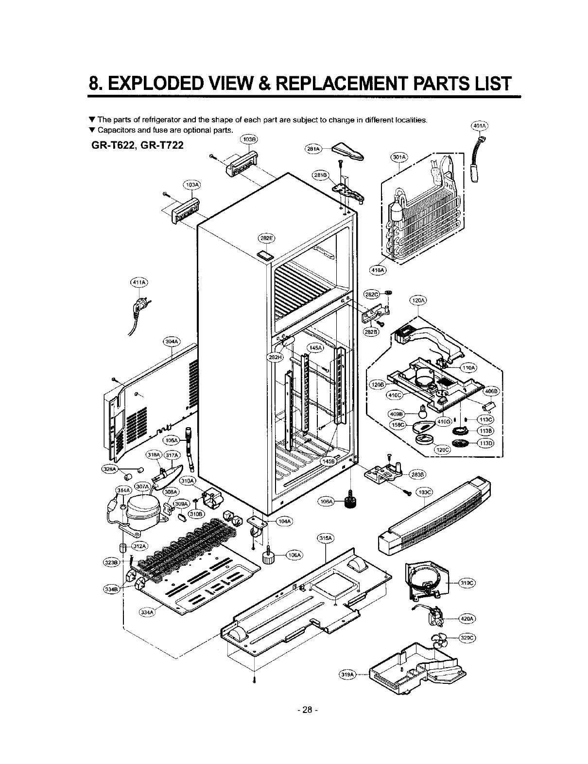
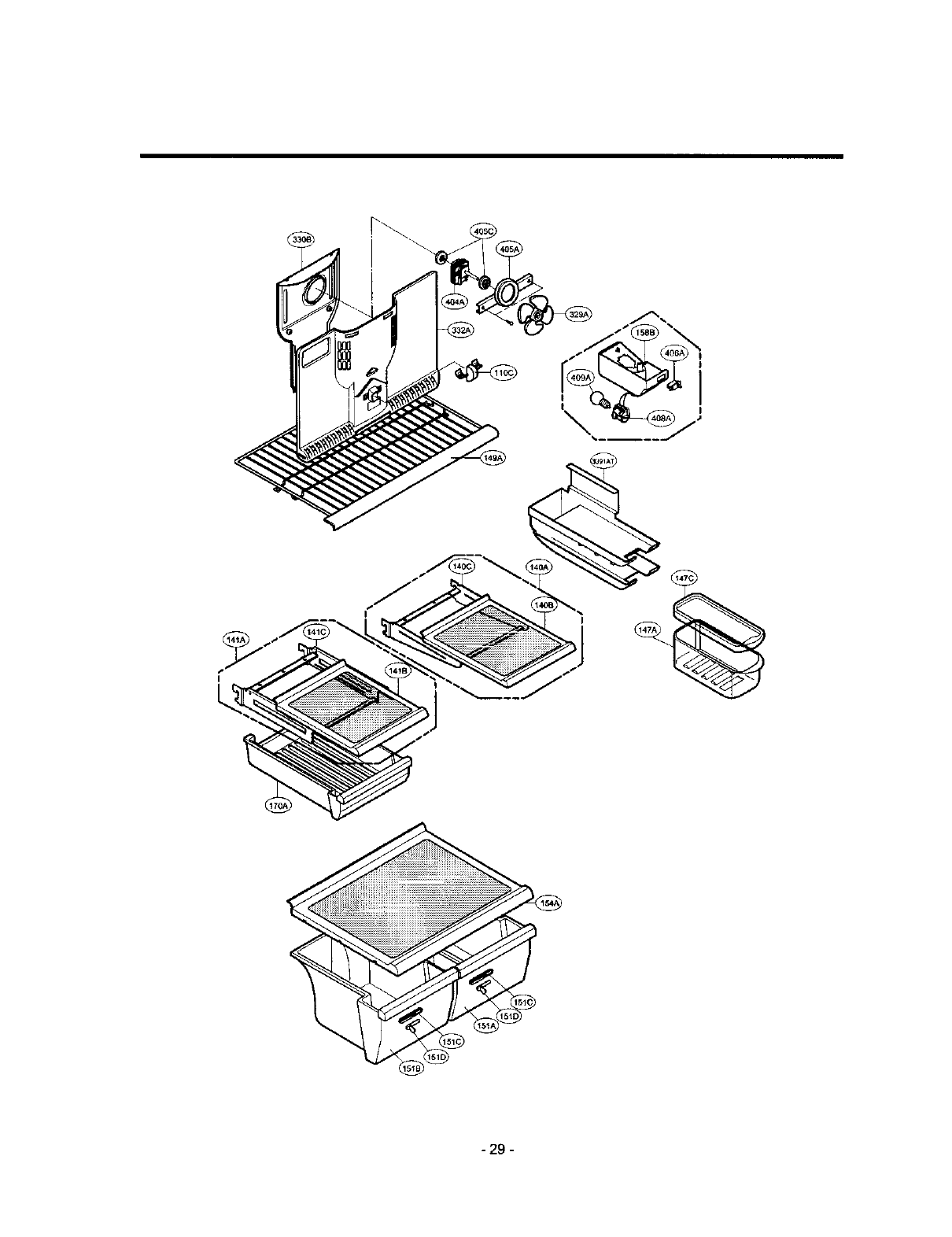
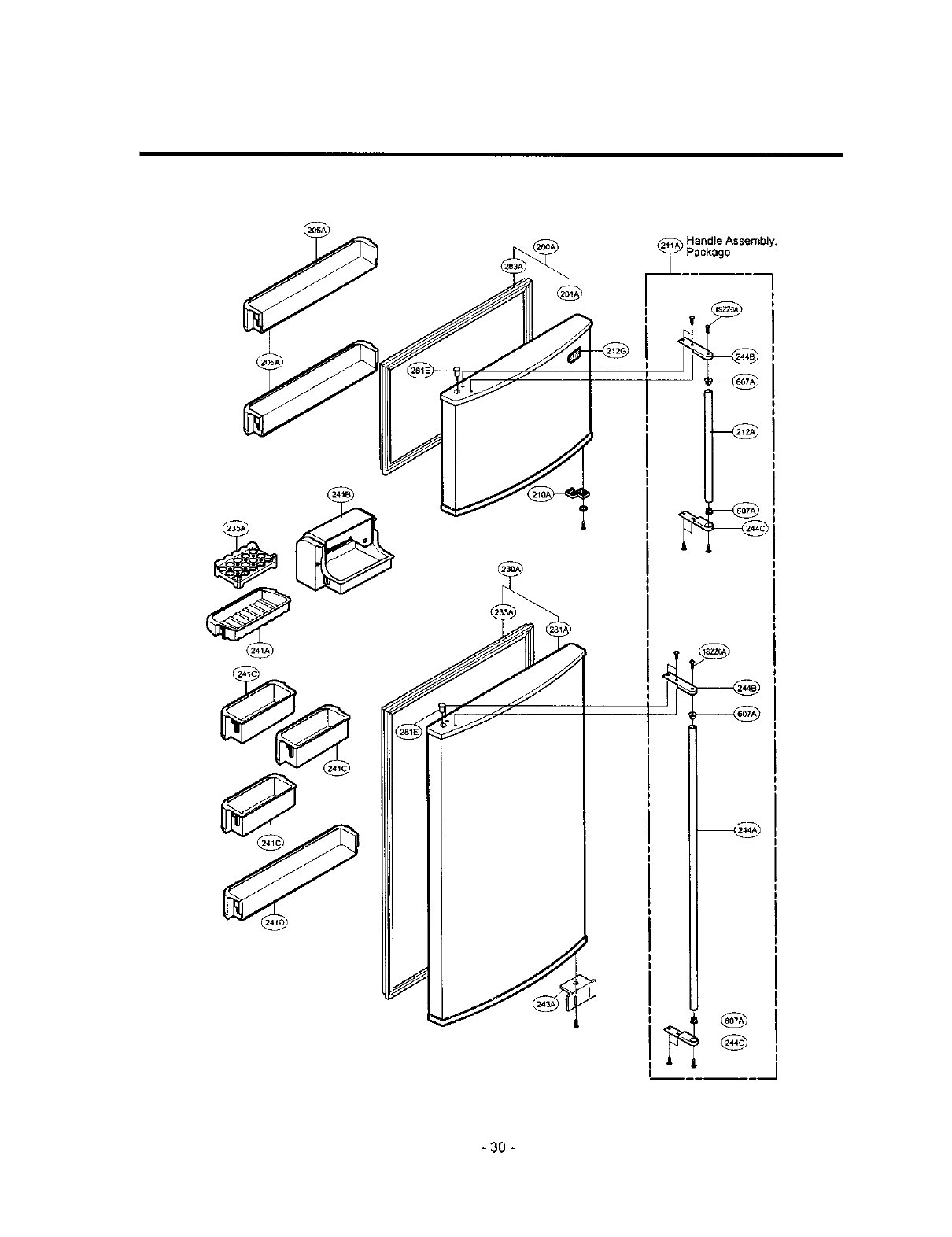
8. EXPLODED VIEW & REPLACEMENT PARTSLIST
•The parts of refrigerator and the shape of each part are subject to change in different localities.
• Capacitors and fuse are optional parts.
GR-T622, GR-T722
I
I
- 28 -
i 29 m
_30 _
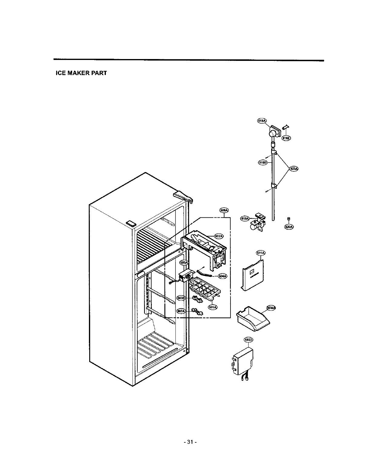
ICE MAKER PART
-31 -
