LINAK A S 13EAXBE Remote control for Actuator system User Manual TD1 280 Microprocessor user ver d eng indd
LINAK A/S Remote control for Actuator system TD1 280 Microprocessor user ver d eng indd
Contents
- 1. User Manual 1
- 2. User Manual 2
- 3. User Manual 3
User Manual 2
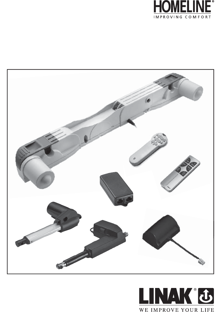
TWINDRIVETM
TD1 280 (Microprocessor)
To learn more about LINAK please visit:
WWW.LINAK.COM
2
3
Preface ................................................................................................................................................................. 4
Important information ....................................................................................................................................... 5
Safety instructions .............................................................................................................................................. 5
Before installation, reinstallation or troubleshooting ..................................................................................... 5
Before start-up .................................................................................................................................................... 5
During operation ................................................................................................................................................ 5
Repairs ................................................................................................................................................................. 6
Misc. on the TWINDRIVETM TD1 280 system ...................................................................................................... 7
Description of the TWINDRIVETM TD1 280 system ............................................................................................. 8
Mounting guidelines for the TWINDRIVETM .............................................................................................. 9
Mounting the handset ................................................................................................................................ 9
Connection to the mains .............................................................................................................................10
The HB20 series ...................................................................................................................................................10
Before start-up .............................................................................................................................................11
RF System (Radio Frequency).......................................................................................................................11
Start-up .........................................................................................................................................................12
Child lock .............................................................................................................................................................14
Handset for massage ..........................................................................................................................................15
How to change the 9V battery ..........................................................................................................................17
Accessories and repair ........................................................................................................................................19
Mains cut-off .......................................................................................................................................................19
Disposal of LINAK’s products .............................................................................................................................20
Mains cut-off (internal) ......................................................................................................................................21
How to mount .....................................................................................................................................................21
Mounting instructions of the massage motor ...........................................................................................23
Labels ................................................................................................................................................................25
Drawing appendix ..............................................................................................................................................26
Manufacturer’s declaration ................................................................................................................................29
LINAK application policy ....................................................................................................................................29
Addresses ............................................................................................................................................................32
Contents
4
Preface
We are delighted that you have chosen a product from LINAK A/S. LINAK
systems are high-tech products based on many years of experience in the
manufacture and development of actuators, electric control boxes, controls,
and chargers. We are also constantly improving our products to meet
customer requirements.
This User Manual will tell you how to install, use, and maintain your LINAK
TWINDRIVETM products.
We are sure that the TWINDRIVETM products will give you many years of
problem-free operation. Before our products leave the factory they undergo
full function and quality testing. Should you nevertheless experience
problems with your systems, you are always welcome to contact our service
departments or service centres.
LINAK subsidiaries and distributors all over the world have authorised
service centres, which are always ready to help you.
LINAK provides a warranty on all its products. This warranty, however, is
subject to correct use in accordance with the specifi cations, maintenance
being done correctly and any repairs being carried out at a service centre,
which is authorised to repair LINAK products.
Changes in installation and use of LINAK systems can affect their operation
and durability. Changes must therefore only be made by agreement with
LINAK A/S and are made at your own risk.
LINAK A/S
5
Safe use of the system is possible only when the operating instructions are
read completely and the instructions contained are strictly observed.
Failure to comply with instructions marked with the ”NOTE” symbol may
result in serious damage to the system or one of its components.
Persons who do not have the necessary experience or knowledge of the
product/products must not use the product/ products. Besides, persons with
reduced physical or mental abilities must not use the product/products, unless
they are under surveillance or they have been thoroughly instructed in the use
of the apparatus by a person who is responsible for the safety of these persons.
Moreover, children must be under surveillance to ensure that they do not play
with the product.
It is important for everyone who is to connect, install, or use the systems
to have the necessary information and access to this User Manual.
If there is visible damage on the product it must not be installed.
Before installation, reinstallation, or troubleshooting:
• Stop the TD1
• Switch off the power supply and pull out the mains plug.
• Relieve the TD1 of any loads, which may be released during the work.
Before start-up:
• Make sure that the system has been installed as instructed in this User
Manual.
• Make sure that the voltage is correct before the system is connected to
the mains. (See TD1 label on page 10).
• System connection. The individual parts must be connected before
connection to the mains.
Safety instructions
Important information
Important information on LINAK® products can be found under the
following headings:
Warning!
Failure to comply with these instructions may result in accidents
involving serious personal injury.
Failing to follow these instructions can result in the product being
damaged or being ruined.

Repairs
In order to avoid the risk of malfunction, all TWINDRIVETM repairs must only
be carried out by authorised LINAK workshops or repairers, as special tools
must be used and special gaskets must be fi tted. TWINDRIVE under warranty
must also be returned to authorised LINAK workshops.
Warning!
If any of the TWINDRIVETM products are opened, there will be a risk of
subsequent malfunction. Furthermore, the warranty will not cover, when
the product has been opened by unautorised personnel.
Warning!
The TWINDRIVETM systems do not withstand to cutting oil.
Warning!
If the supply cable is damaged the product must not be used or connected
to the mains. The product has to be replaced by a new to avoid a safety
hazard.
6
(continued)
During operation
• Take care that the cables are not damaged.
• Unplug the mains cable on mobile equipment before it is moved.
• The products must only be used in an environment, which corresponds to
their IP protection.
• Statement – for all intentional and unintentional radiators:
Changes or modifi cations not expressly approved by the party responsible
for compliance could void the user’s authority to operate the equipment.
• Statement for Digital devices for Class B:
NOTE: This equipment has been tested and found to comply with the
limits for a Class B digital device, pursuant to part 15 of the FCC Rules.
These limits are designed to provide reasonable protection against harmful
interference in a residential installation. This equipment generates, uses
and can radiate radio frequency energy and, if not in-stalled and used in
accordance with the instructions, may cause harmful interference to radio
communications. However, there is no guarantee that interference will
not occur in a particular installation. If this equipment does cause harmful
interference to radio or television reception, which can be determined by
turning the equipment off and on, the user is encouraged to try to correct
the interference by one or more of the following measures:
- Reorient or relocate the receiving antenna.
- Increase the separation between the equipment and receiver.
- Connect the equipment into an outlet on a circuit different from that to
which the receiver is connected.
- Consult the dealer or an experienced radio/ TV technician for help.
Misc. on the TWINDRIVETM TD1 280 system
This system is a TWINDRIVE system developed for leisure beds and for indoor
use in private homes.
We advise children and disabled persons not to use the TD1 system
without supervision.
Warranty
There is 36 months’ warranty on the TWINDRIVETM products TD1 and HB10/
HB20 against manufacturing faults calculated from the production date of
the individual products (see label). LINAK A/S’ warranty is only valid in so far
as the equipment has been used and maintained correctly and has not been
tampered with. Furthermore, the system must not be exposed to violent
treatment. In the event of this, the warranty will be ineffective/invalid.
For further details, please see LINAK A/S’ ordinary conditions of sale.
Maintenance
Clean dust and dirt on the outside of the system, at appropriate intervals and
inspect them for damage and breaks.
Inspect the connections, cables, and plugs and check for correct functioning
as well as fi xing points.
Check emergency lowering batteries yearly for their full capacity.
If not, they have to be changed. Type 9V 6F22 or 6LR61.
The system must only be cleaned with a fi rmly wrung cloth. The cleaners
and disinfectants must not be highly alkaline or acidic
(pH value 6-8).
It is not allowed to use solvents for cleaning up.
7
Description of the TWINDRIVETM TD1 280 system
Each TWINDRIVETM TD1 unit consists of 1 - 2 internal motors and a built-in
control box function which makes it a very compact unit. The mains cable
is fi xed. Only the handset and optional 1 - 2 external actuators must be
connected.
The TWINDRIVETM TD1 system range contains the following products:
• 1 TD1 - 280
• 1 HB20 IR Receiver
• 1 HB20 IR Transmitter
or
• 1 HB20RF Transmitter
• 1 RFRL Receiver
Optional
• 9V batteries
• 1 - 2 actuators (LA27 or LA31)
• Mains cut-off
• Massage motors
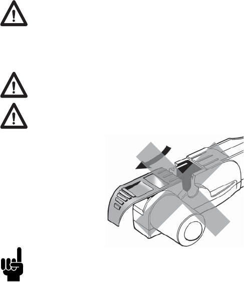
Be sure that the closing devices are in place before the TD1 is used.
Application of the TWINDRIVETM TD1 280 system:
Irrespective of the load the duty cycle 10% ~ 6 min./ hour or max.
2 min. at continuous use stated in the data sheets, must NOT be
exceeded as this will result in a superheating of the motor and
the spindle nut. Exceeding the duty cycle will result in a dramatic
reduction of the life of the system.
Do not turn the system if it is not mounted in a bed.
Do not open the closing device on the TD1 during operation as this
may cause malfunction and possibility of personal injuries.
8
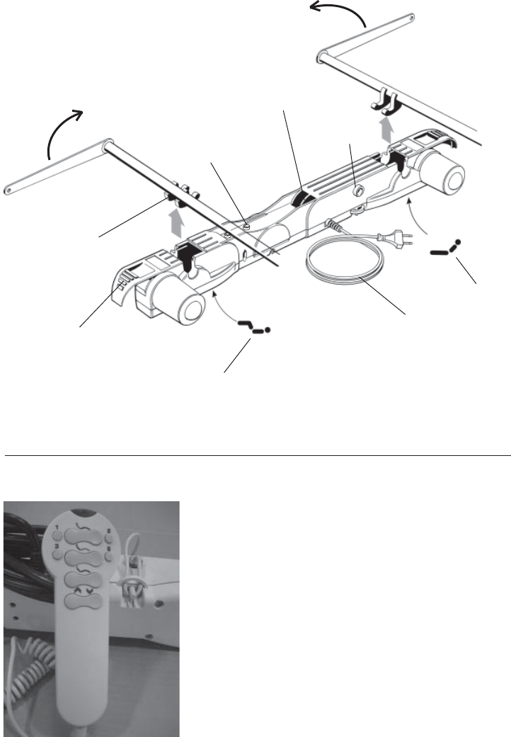
9
Handset
socket
Mains cable
Twist bracket
for 2 x 9V batteries
Footrest
Headrest
Closing device
Connection for external
actuators/massage device
Mounting guidelines for the TWINDRIVETM 280 system
Figure 1
(Assembly overview)
Mounting the handset
Recommended usage of the strain relief
the PCB. Otherwise the DIN-plug and print
might be damaged when overstraining the
cable.
10
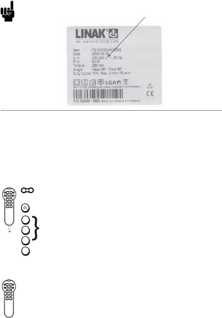
Please note that the TD1 must only be connected to the voltage stated
on the label.
Connection to the mains
IR system (infrared)
Infrared system consist of 2 units. 1 receiver mounted as a standard handset
with cable in the TD1 and a wireless unit.
The wireless unit (Transmitter) is the actual handset. In cases where the
Transmitter is damaged or has been lost is it possible to operate the
TWINDRIVE system with the receiver.
The HB20 (Receiver)
with cable
up/down operation
(1-4 channels)
common operation up/down (option)
Store Button
Memory positions
(3 positions)
3
2
1
S
The HB20 without massage (Transmitter )
without cable
Same function as Receiver
11
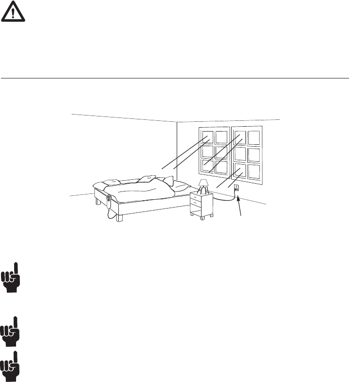
To ensure ooptimal functioning of the system the receiver must not be
covered. Example of a good placement see page 19.
1. Remove plastic strip
Before start-up
Check that the transmission channel on the transmitter and the
receiver is the same. If 2 beds are placed beside each other each bed
must drive on their own channel to avoid undesirable drive.
RF System (Radio Frequency)
RF system consist of 3 units. Receiver, cable and transmitter.
Mounting:
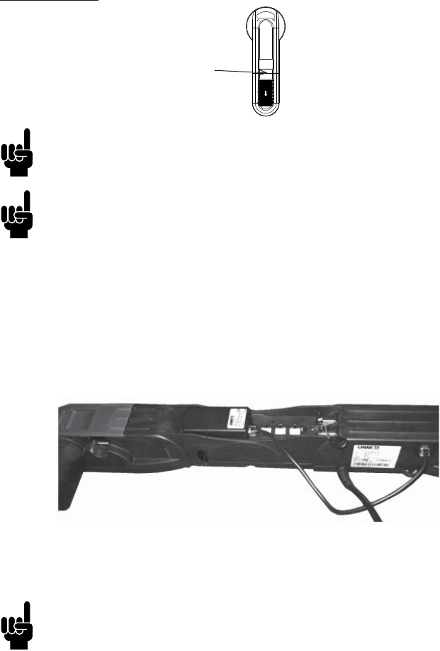
Place the RFR box in the groove and connect the cable in one of the ports of
the RFR box and then into TD.
Do not drill holes into the TD to fasten the RFR box.
Start-up:
The RFR box can accept commands from up to 2 RF handsets.
From the factory the RFR box cannot recognize any RF handsets at all and must
be matched to the RF handset(s) by the end-user/bed manufaccturer before
these can control the TD operation.
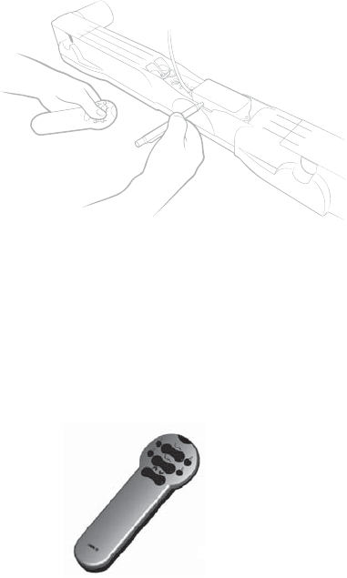
Activating the learning mode:
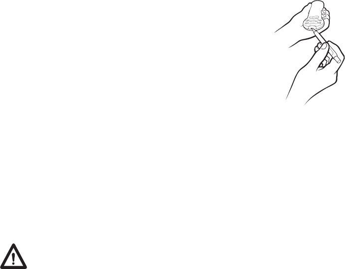
• Activate the reset key on the RFR by using a pen or similar to keep the
button pressed.
• Keeping the reset key activated; the RF handset(s) must be activated one
at a time by pressing a random key on the RF handset. The RF handset ID’s
are stored in the TD memory and at the same time, previous RF handset
ID’s are erased. If you want to match 2 RF-handsets you should keep
pressed the reset key until you have stored both handsets (don’t release
before you matched the second handset, otherwise it will recognize only
the fi rst one).
• After having activated the RF handset keys; the reset key must be released.
• If no RF handsets keys are activated during the matching procedure; no
changes are made in the ID memory of the TD.
HB20RF
H
12

Initialisation of the TD1 memory system.
To ensure optimum drive of the systems with memory, infrared and
extra channels must be run out to the outward position and in again
before use. This drive (out + in) must be done without stops.
How to store
• Drive to the desired position
• Push “S”
• Immediately afterwards the desired memory position (1, 2 or 3)
• The position is now stored
Drive to stored memory position
• Push (1, 2 or 3) keep the button down until the position has been reached
The system runs sequentially.
13
Disturb of RF signals
Please be aware that if you use the TD the fi rst time or it has been
disconnected from both mains and battery power, the TD RF receiver
may need a very short time to be able to receive a signal.
Please be aware that the other equipment (as e.g. doorbells), which use
the 433MHz can disturb the RF signal.
Under some circumstances it is not possible to run 2 or more TD’s at the
same time (RF signal gets distrubed).
Child lock (only by RF Handset)
To enable the function the position of the switch in the front of the
transmitter must be changed.
To unlock the handset press up and down keys of the 2nd row
at the same time for one sec. When the blue LED turns
on the handset is unlocked for 10 sec. after last key press.
Then it automatically locks again. If the up + down key is
pressed more than 2 sec. the handset will lock again.
If the handset is locked and the user tries to operate it,
it will give a short fl ash with the LED to indicate “key is
pressed, but handset is locked”.
Enable/Disable Child lock
To enable the function the position of the switch in the front of the
transmitter must be changed.
N.B The Child lock only locks actuator functions. Therefore, it is disabled
while the HB is in massage command mode.
Unlock of Child lock
Press up and down keys of the 2nd row at the same time for one sec. When
the blue LED turns on the handset is unlocked.
The handset is not unlocked If the key is not are released again before
the blue led turns off.
Automatic lock
The handset is unlocked for 10 sec. after last key press. Then it automatically
locks again.
Signaling of handset is locked
If the handset is locked and the user tries to operate it, it will give a short
fl ash with the LED to indicate “key is pressed, but handset is locked”.
14
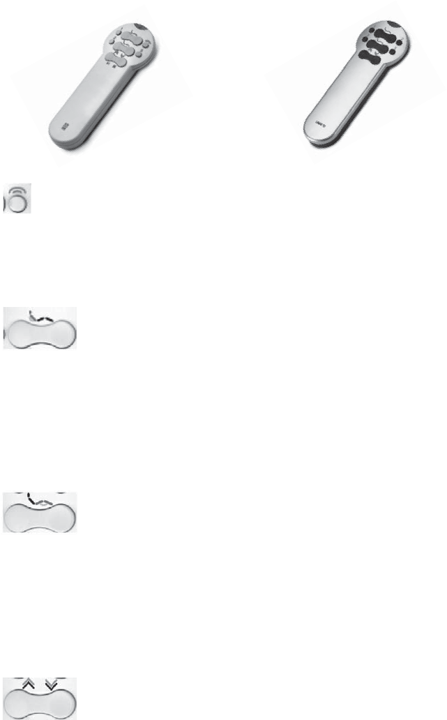
Usage:
Enter/exit massage command mode
Sets the control in massage mode for controlling the massage functions (LED fl ashing)
or returns to normal mode for controlling the bed adjustment (LED off).
Pressing this key has no infl uence on the TWINDRIVE unit except from waking it up to
make its response time to massage commands shorter. If no keys are pressed in 10 min.
the control will automatically go to normal mode (LED off).
Controlling the backrest massage motor
Short key press turns the backrest massage motor on or off (Left key on, right key off).
Turning on a motor, which has been turned off by turning the intensity to off, starts
the motor with lowest confi gured intensity.
Keep key pressed to adjust the intensity up or down (Left key up, right key down).
Keeping the down key pressed will turn the motor off when going below minimal
intensity. The intensity can be controlled when running in a massage program, but the
massage program will be temporarily halted and both motors are run with currently
chosen intensity until up/down-key is released.
Controlling the leg rest massage motor
Short key press turns the leg rest massage motor on or off (left key on, right key off).
Turning on a motor, which has been turned off by turning the intensity to off, starts
the motor with lowest confi gured intensity.
Keep key pressed to adjust the intensity up or down (left key up, right key down).
Keeping the down key pressed will turn the motor off when going below minimal
intensity. The intensity can be controlled when running in a massage program, but the
massage program will be temporarily halted and both motors are run with currently
chosen intensity until up/down-key is released.
Controlling the massage program
Short key press on left key turns on a massage program (wave, pulse etc.) or change to
15
HB220G1+00003
(IR Transmitter)
HB22RF2000
(RF Transmitter)
Handset for massage

16
next program if a program is already activated. Starting a massage program always
turns on both motors at current intensity.
Short key press on right key turns off both massage motors no matter if it is running in
a massage program, or separately.
Keep key pressed to adjust the motor change speed up or down (left key down, right
key up)
Store and recall massage settings.
2 massage settings can be stored.
Adjust the massage to the preferred settings. Press the “S” key followed by either key
“1” or “2”. To recall a pervious stored setting pres key “1” or “2”.
In general
Massage will turn off automatically 10 min after the last adjustment of the
settings.
Adjusting the bed will turn off the massage, but massage will automatically
start up again afterwards.
When turning on a single massage motor it will start up with the same
intensity as it was last time it was running as a single motor.
When turning on a massage program it will start up with the same settings
(program, motor change speed, intensity) as it was last time.
Turning on a massage function can also be done by keeping the up key
pressed. Then it will turn on, and after a short delay adjust the intensity up.
Massage functions can only be controlled by the transmitter. The receiver is
a standard hand control.
Pressing any key on the receiver will stop the massage, and adjust the
bed according to the key pressed. After releasing the key, massage will
automatically start up again.
In case of any error: current-limitation, high temperature or short-circuit,
the massage system will stop both motors, even if only one motor is
affected.
Normal operation
In normal mode to adjust the bed position, the hand control is working
exactly as a normal Handset without massage functionality, except there are
only 2 memory positions instead of 3.
If there are any extra motors in the system, the keys to control these motors
will, as normal, be placed between the leg rest keys and the “reset and
massage program” keys.
17
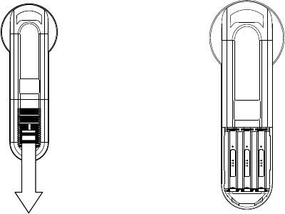
Changing of the batteries (Transmitter)
1. Remove the battery cover (see Figure 1).
2. Use a blunt instrument to remove the battery.
3. Place 3 new batteries type R03 or LR03 (AAA) in the transmitter.
Direction of how to place the batteries in the transmitter is showed in
Figure 2
Figure 1
Figure 2

18
Exchange/connection of 9V batteries (Type 6F22 or 6LR61)
1. Remove the clamps from the battery (Figure 3).
2. Use a blunt instrument with a diameter of Ø6 mm to remove the battery
( Figure 4).
3. Push the battery upwards via the two holes in the bottom of the unit
( Figure 5).
Figure 5Figure 3 Figure 4
Disposal of batteries.
"Details regarding safe disposal of used and leaking batteries:
Batteries should be disposed in accordance with appropriate federal, state
and local regulations. LINAK recommends that used or leaking batteries are
disposed through local recycling system. Please do not throw used or leaking
batteries in normal household waste or in nature. This will cause damage to
the enviroment.
How to deal with leaking batteries.
Leaking batteries should be disposed as described above.
If leaking batteries are discovered in the product the batteries must be
removed at once to minimise damage to the product. If leaking batteries are
left in the product it might become defect.
It is recommended to use plastic gloves when handeling leaking batteries.
The contents of a leaking batteries can cause chemical burns and respiratory
irritation.
If exposed to the contents of a leaking battery, please wash with soap and
water. If irritation persists, please seek medical attention. In case of eye
contact, please fl ush eyes thoroughly with water for 15 minutes and seek
medical attention."
19
Accessories and repair
Ordering accessories
Order from your nearest LINAK® dealer or subsidiary.
Accessories
Please contact your nearest LINAK dealer for information.
Repairs
Systems should only be repaired by an authorised LINAK service centre or
engineer. Systems to be repaired under warranty must be sent to an
authorised LINAK service centre.
Warning!
By unauthorised opening of the system there is a risk that it may
malfunction at a later date. Furthermore, the warranty will not cover,
when the product has been opened by unautorised personnel.
Spare parts
Please contact your nearest LINAK dealer for information on spare parts.
Receiver Mains cut-off
“click click”
If you observe that the mains cut-off does not disconnect, but keeps
clicking when the TWINDRIVE motor is running it may be because the
IR-receiver is exposed to sunlight or light from a lamp. If this should
be the case we recommend placing the receiver at an edge of the bed
where this cannot occur.
Operation of 2 beds at the same time is not possible.
Other IR systems in the same room may infl uence the TWINDRIVE IR
system. If operating a different IR system in the same room for example
a TV transmitter, is it in some cases not possible to operate the bed and
sometimes the mains cut-off is also clicking.
Disturb of IR-system

20
Disposal of LINAK’s products
As LINAK’s customers often ask us how our products can be disposed of or
scrapped we have prepared this guidance that enables a classifi cation to
different waste fractions for recycling or combustion.
Guidance
We recommend to disassemble our product into as many fractions as possible
at the disposal and try to make it recycable. As examples of main groups
within waste fractions we can mention:
Metal, plastic, cable shoe, combustible waste, and collection for recovery.
Some of these main groups can be subdivided, e.g. metal can be divided into
iron, stainless steel and aluminium, and alloy steel. Plastic can e.g. be divided
into ABS, PA, PE, and PP.
As an example of sorting, please fi nd below a list stating in which recycling
groups the differenct components of LINAK’s products ought to be placed:
Product main
groups
Scrap Cable
scrap
Electronics
scrap
Plastic recycling
or combustin
Comments
LA27 X X X The metals can be sorted
for steel or aluminum
LA31 X X X X The metals can be sorted
for steel or aluminum
TD1 X X The metals can be sorted
for steel or aluminum
HB20 X X X
MD1 X X X
RFRL X X X
Main groups of disposal
By now almost all our casted plastic parts are supplied with an interior code for
plastic type and fi bre contents, if any.
Product Components Recycling group
Actuator: Spindle and motor Scrap
Plastic housing Plastic recycling or combustion
Cable Cable scrap or combustion
Massage motor: Plastic housing Plastic recycling or combustion
Cable Cable scrap or combustion
TWINDRIVE: PCB Electronics scrap
Plastic housing Plastic recycling or combustion
Cable Cable scrap
Trafo Scrap
Batteries Recovery
Spindle and motor Scrap
Handset/Control: Plasic housing Plastic recycling or combustion
Cable Cable scrap
PCB Electronics scrap
21
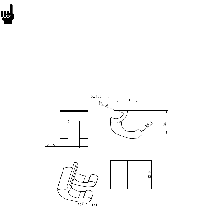
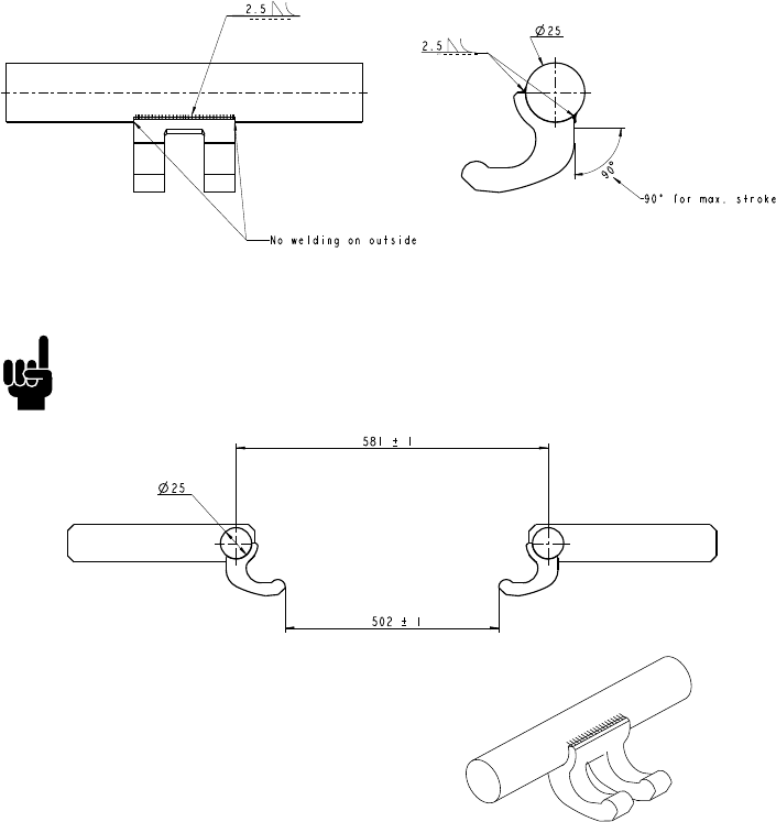
1) For the TD1 it is important that one does not weld on the outside of the
twist bracket because there is not space for a welding seam in the motor
housing. One may weld the bracket along the whole length of its ends.
How to mount (in chronological order):
Welding the twist bracket on the frame (0701030)
Mains cut-off
The mains cut-off function disconnect the power to the TD1 system, if the
system is not used. The mains cut-off is 100% maintance-free.
The mains cut-off is available in 2 versions - an external version or an internal
version.
The external version is a small box placed on the plug of the mains cable.
The internal version is integrated in the TD1 and thereby not visible. TD1
systems with internal mains cut-off are labelled TD1XXXXXXXXX2XX.
Please observe that TD1 systems with mains cut-off do not work in
houses with ”Hausfreischaltung”.
22
3) Before mounting, both mounting brackets must be pulled out to their
outer position by pushing them back. This gives freedom of movement to
the bed bracket. Mounting is done by pushing the bed bracket into the TD1
unit and thereafter pushing the mounting brackets back again.
Example for correct welded twist
bracket to the bedframe.
It is very important that the axle distance is kept.
2) To maintain the correct angle of rotation of the headrest and the footrest
it is important that the twist bracket is welded according to the above
instructions. Non-complliance with the instructions could lead to a smaller
angle of rotation or in a worst case damage to TD1.
23
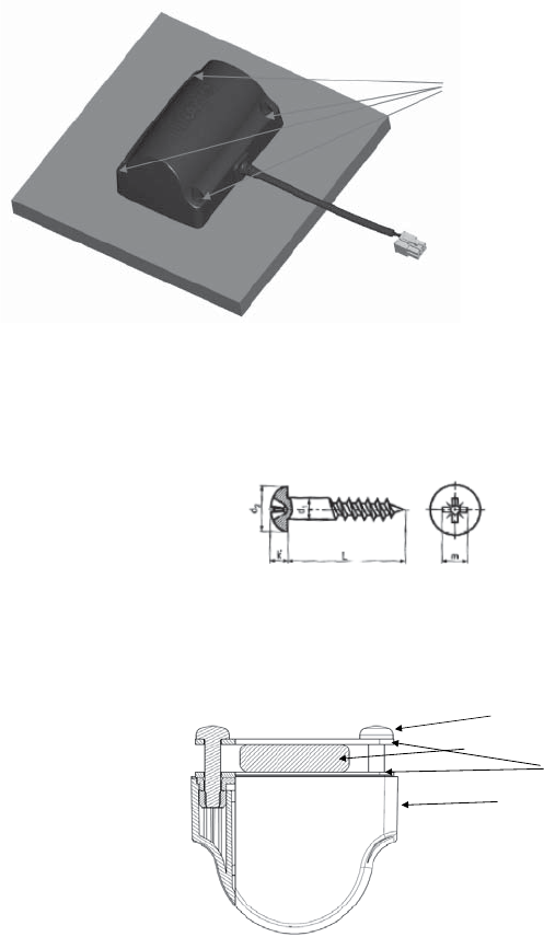
Mounting instructions of the massage motor:
Mounting on plate:
Is mounted with 4 screws
The massage unit is mounted with 4 x 4 mm round headed wood screwx with
fl at underside. The head must be 8 mm in diameter and in length 19 mm +
the thickness of the plate where the massage motor is mounted. Torque max.
2 Nm + resistance in the plate.
Massage Motor
Slat
Bracket
Screw
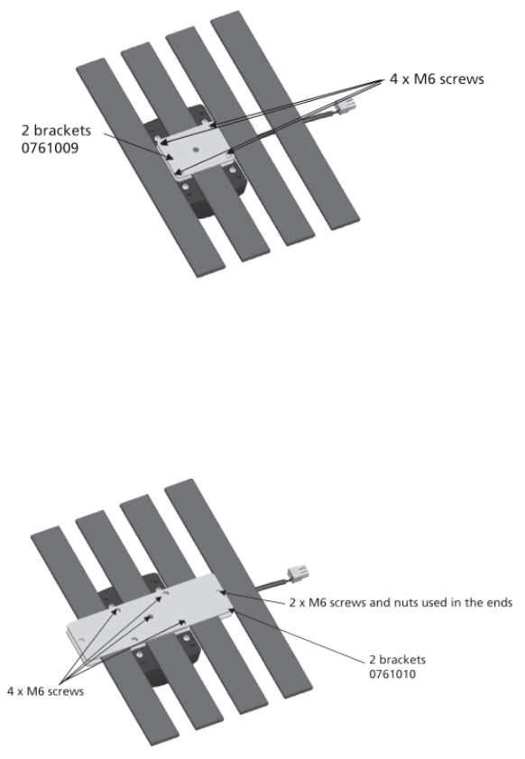
Mounting instructions of the massage motor by using brackets:
The massage unit is mounted with 4 x M6 round headed machine screws
with fl at underside. 15 to 20 mm long + the thickness of the bracket. Torque
max. 2-3 Nm. 2 Brackets must be used – one on each side of the slat.
24
Mounted on one slat:
The massage motor is mounted to the slat by using 2 brackets 0761009 and
4 x M6 screws of good quality. Inside the motor 4 self-locking nuts avoid the
mounting screws to get loose.
Mounted on three slats:
25
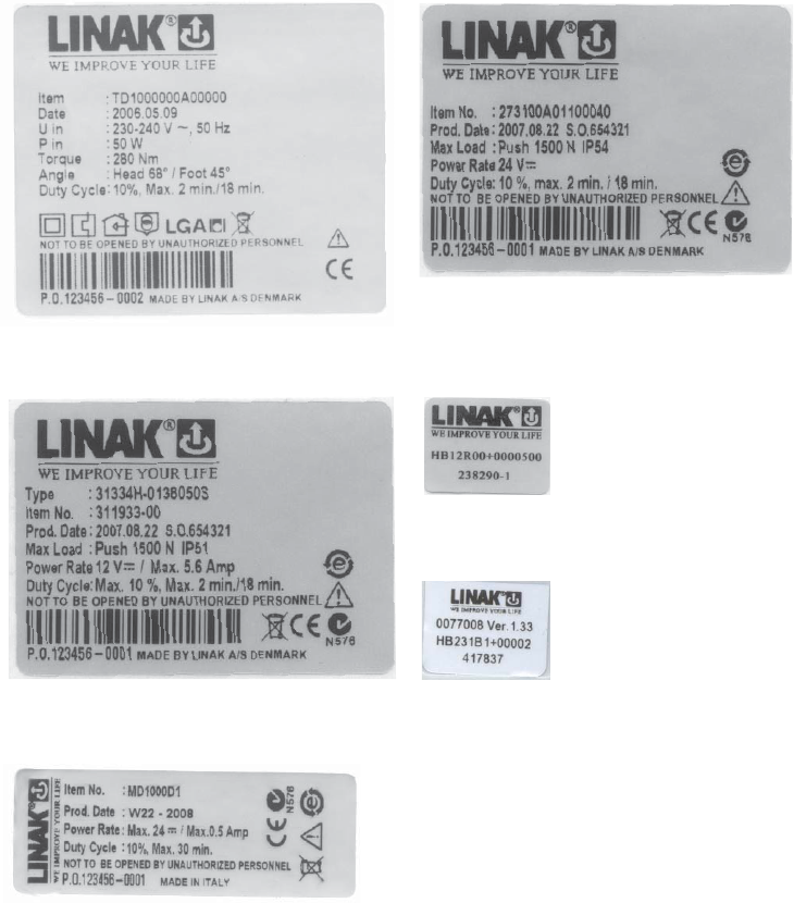
Label for the Handset HB20:
Label for the Handset HB10:
Label for the TWINDRIVETM TD1 System
Label for the LA31
Label for the LA27
Label for the Massage Motor
26
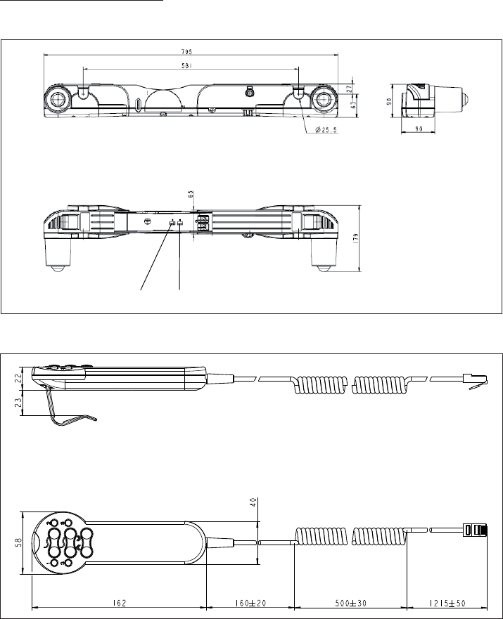
DRAWING APPENDIX
TWINDRIVETM TD1 System:
CH 1 CH 2
HB20 Receiver
27
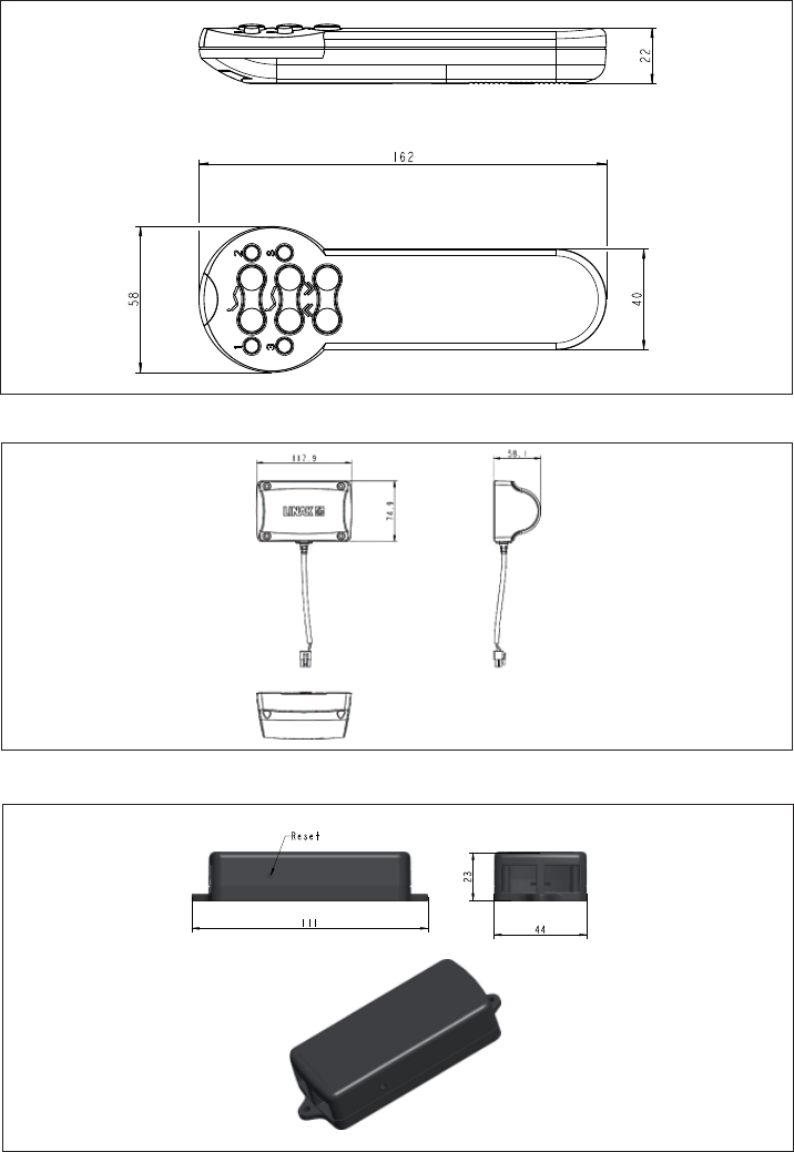
HB20 Transmitter
Massage motor MD1
RFR box
44
111
23
Reset
28
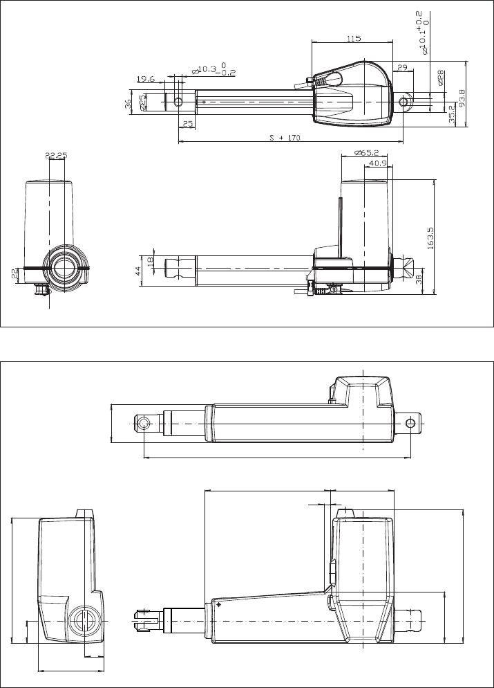
LA31
LINAK A/S
LA31002C
INSTALLATIONDIM.=STROKE + ADDITION
80.75
23.5
27.5
153
7.4
62.9
47
.
152.75 78
163
LA27

29
LINAK APPLICATION POLICY
The purpose of the application policy is to defi ne areas of responsibilities
in relation to applying a LINAK product defi ned as hardware, software,
technical advice, etc. related to an existing or new customer application.
LINAK products as defi ned above are applicable for a wide range of
applications within the Medical, Furniture, Desk,as and Industry areas. Yet,
LINAK cannot know all the conditions under which LINAK products will be
installed, used, and operated, as each individual application is unique.
The suitability and functionality of the LINAK product and its performance
under varying conditions (application, vibration, load, humidity,
temperature, frequency, etc.) can only be verifi ed by testing, and shall
ultimately be the responsibility of the LINAK customer using any LINAK
product.
LINAK shall be responsible solely that the LINAK products comply with the
specifi cations set out by LINAK and it shall be the responsibility of the LINAK
customer to ensure that the specifi c LINAK product can be used for the
application in question.
Manufacturer's declaration
Implementation with regard to the Community
legislation on machinery
Directive 98/37/EC attachment II B:
LINAK A/S, subsidiaries or representatives,
(see back cover)
prohibit that actuators are put into service
until the machinery into which the actuator is to be
incorporated has been declared in conformity with
the provisions of all relevant Directives.
Bent Jensen
LINAK A/S
30
31

Copyright© LINAK 2009.04 MA-M9-02-236-D LINAK A/S reserve the right to make technical alterations
The user is responsible for determining the suitability of LINAK
products for a specifi c application.
LINAK A/S takes great care in providing accurate and up-to-
date information on its products. However, due to continuing
developments in order to improve its products, LINAK products
are subject to frequent modifi cations and changes without prior
notice. Therefore, LINAK cannot guarantee the correct and actual
status of said information on its products. While LINAK uses its
best efforts to fulfi l orders, LINAK cannot, for the same reasons
as mentioned above, guarantee the availability of any particular
product. Therefore, LINAK reserves the right to discontinue
the sale of any product displayed on its website or listed in its
catalogues or other written material drawn up by LINAK.
All sales are subject to the Standard Terms of Sale and Delivery
for LINAK A/S. For a copy hereof, please contact LINAK.
FACTORIES
CHINA
LINAK (Shenzhen) Actuator Systems, Ltd.
Phone: +86 755 8610 6656 . Fax: +86 755 8610 6990
E-mail: sales@linak.cn . www.linak.cn
DENMARK
LINAK A/S . Group Headquarters Guderup
Phone: +45 73 15 15 15 . Fax: +45 74 45 80 48
Fax (Sales): +45 73 15 16 13
E-mail: info@linak.com . www.linak.com
SLOVAKIA
LINAK Slovakia s.r.o.
Phone: +421 517563 414 . Fax: +421 517563 410
E-mail: jp@linak.sk . www.linak.com
USA
LINAK U.S. Inc.
North and South American Headquarters
Phone: +1 502 253 5595 . Fax: +1 502 253 5596
E-mail: info@linak-us.com . www.linak-us.com
SUBSIDIARIES
AUSTRALIA
LINAK Australia Pty. Ltd
Phone: +61 3 8796 9777 . Fax: +61 3 8796 9778
E-mail: sales@linak.com.au . www.linak.com.au
AUSTRIA
LINAK GmbH
Phone: +43 2746 21036 . Fax: +43 2746 21044
www.linak.at
BELGIUM & LUXEMBOURG
LINAK Actuator-Systems NV/SA
Phone: +32 (0)9 230 01 09 . Fax: +32 (0)9 230 88 80
E-mail: info@linak.be . www.linak.be
BRAZIL
LINAK do Brasil Comércio de Atuadores Ltda.
Phone: +55 (11) 6832-7070 . Fax: +55 (11) 6832-7060
E-mail: linakbrasil@ig.com.br . www.linak.com.br
CANADA
LINAK Canada Inc.
Phone: +1 905 821 7727 . Fax: +1 905 821 4281
E-mail: info@linak.ca . www.linak.ca
CZECH REPUBLIC
LINAK C&S S.R.O.
Phone: +420581741814 . Fax: +420581702452
E-mail: ponizil@linak.cz . www.linak.cz
DENMARK
LINAK DANMARK A/S
Phone: +45 86 80 36 11 . Fax: +45 86 82 90 51
E-mail: linak@linak-silkeborg.dk . www.linak.dk
FINLAND
LINAK OY
Phone: +358 10 841 8700 . Fax: +358 10 841 8729
E-mail: linak@linak.fi . www.linak.fi
FRANCE
LINAK FRANCE S.A.R.L
Phone: +33 (0)2 4136 3434 . Fax: +33 (0)2 4136 3500
E-mail: linak@linak.fr . www.linak.fr
GERMANY
LINAK GmbH
Phone: +49 6043 9655 0 . Fax: +49 6043 9655 60
E-mail: info@linak.de . www.linak.de
INDIA
LINAK A/S India Liaison Office
Phone: +91 80 2299 6533 . Fax: +91 80 2224 3863
E-mail: info@linak.in . www.linak.in
IRELAND
LINAK UK Limited
Phone: +44(0)121 544 2211 . Fax: +44(0)121 544 2552
E-mail: stephen@linak.co.uk . www.linak.co.uk
ITALY
LINAK ITALIA S.r.l.
Phone: +39 02 48 46 33 66 . Fax: +39 02 48 46 82 52
E-mail: info@linak.it . www.linak.it
JAPAN
LINAK K.K.
Phone: +81 45 533 0802 . Fax: +81 45 533 0803
E-mail: linak@linak.jp . www.linak.jp
MALAYSIA
LINAK A/S Asian Representative Office
Phone: +60 4 210 6500 . Fax: +60 4 226 8901
E-mail: info@linak-asia.com . www.linak-asia.com
NETHERLANDS
LINAK Actuator-Systems B.V.
Phone: +31 76 5 42 44 40 . Fax: +31 76 5 42 61 10
E-mail: info@linak.nl . www.linak.nl
NEW ZEALAND
LINAK New Zealand Ltd.
Phone: +64 9580 2071 . Fax: +64 9580 2072
E-mail: nzsales@linak.com.au . www.linak.co.nz
NORWAY
LINAK Norge AS
Phone: +47 32 82 90 90 . Fax: +47 32 82 90 98
E-mail: info@linak.no . www.linak.no
POLAND
LINAK Polska
Phone: +48 (22) 500 28 74 . Fax: +48 (22) 500 28 75
E-mail: dkreh@linak.com . www.linak.pl
SPAIN
LINAK Actuadores S.L.
Phone: +34 93 588 27 77 . Fax: +34 93 588 27 85
E-mail: linakact@linak.es . www.linak.es
SWEDEN
LINAK Scandinavia AB
Phone: +46 8 732 20 00 . Fax: +46 8 732 20 50
E-mail: info@linak.se . www.linak.se
SWITZERLAND
LINAK AG
Phone: +41 43 388 31 88 . Fax: +41 43 388 31 87
E-mail: info@linak.ch . www.linak.ch
TAIWAN
LINAK A/S Taiwan Representative Office
Phone: +886 2 250 80296 . Fax: +886 2 2508 3604
E-mail: info@linak.com.tw . www.linak-asia.com
TURKEY
LINAK A/S Turkey Representative Office
Phone: +90 312 4726338-59 . Fax: +90 312 4726635
E-mail: vozen@linak.com.tr . www.linak.com.tr
UNITED KINGDOM
LINAK UK Limited
Phone: +44(0)121 544 2211 . Fax: +44(0)121 544 2552
E-mail: sales@linak.co.uk . www.linak.co.uk
DISTRIBUTORS
ARGENTINA
NOVOTEC ARGENTINA SRL
Phone: +[54] (11) 4303-8900/89 . Fax: +[54] (11) 4032-0184
E-mail: info@novotecargentina.com
www.novotecargentina.com
COLOMBIA
MEM Ltda
Phone: +[57] (1) 334-7666 . Fax: +[57] (1) 282-1684
E-mail: servicioalcliente@memltda.com.co
www.memltda.com.co
INDONESIA
PT. HIMALAYA EVEREST JAYA
Phone: +6 221 544 8956/65 . Fax: +6 221 619 4658/1925
E-mail: hejplastic-div@centrin.net.id
IRAN
Bod Inc.
Phone: +98 21 88527255 . Fax: +98 21 88514037
E-mail: mail@bod.ir . www.bod.ir
MEXICO
ILSA S.A. de C.V.
Phone: +[52] (55) 5388-3960 . Fax: +[52] (55) 5388-3966
E-mail: linak@ilsamexico.com . www.ilsamexico.com
RUSSIAN FEDERATION
000 FAM
Phone: +7 812 3319333 . Fax: +7 812 3271454
E-mail: purchase@fam-drive.ru . www.fam-drive.ru
SINGAPORE
SERVO DYNAMICS PTE. Ltd.
Phone: +65 6844 0288 . Fax: +65 6844 0070
E-mail: servodynamics@servo.com.sg . www.servo.com.sg
SOUTH AFRICA
Industrial Specialised Applications CC
Phone: +27 11 312 2292 or +27 11 2077600
Fax: +27 11 315 6999
www.stabilus.com
SOUTH KOREA
UNITEK ENG.
Phone: +82 2 567 0888 . Fax: +82 2 3453 1177
E-mail: unitekeng@unitekeng.co.kr . www.unitekeng.co.kr
UNITED ARAB EMIRATES
Mechatronics
Phone.: +971 4 267 4311 . Fax: +971 4 267 4312
E-mail: mechtron@emirates.net.ae
www.mechatronics.ae
For contact details on other countries please visit
www.linak.com or contact:
LINAK INTERNATIONAL
Fax: +45 74 45 90 10
E-mail: info@linak.com . www.linak.com