LINKSYS CGV2W 2.4GHz Wireless mini-PCI Card User Manual Manual
LINKSYS LLC 2.4GHz Wireless mini-PCI Card Manual
LINKSYS >
Manual

54Mbps 802.11g Wireless LAN Card
User’s Manual
Information in this document is subject to change without notice. No part of this document may be
reproduced or transmitted in any form or by any means, electronic or mechanical, for any purpose,
without the express written permission of the seller.
The seller provides this documentation without warranty, term, or condition of any kind. The seller
may make improvements or changes in the product(s) and/or the program(s) described in this
documentation at any time.
Other product and company names herein may be trademarks of their respective owners.
2002 All rights reserved.
Rev: 01
January 2003
I
Contents
About This Manual........................................................................................................................................................ V
Chapter 1 Introduction............................................................................................................................................... 1
Wireless LAN Basics ................................................................................................................................................... 2
Local Area Network (LAN)........................................................................................................................................................2
Ad-Hoc Mode ............................................................................................................................................................................3
Infrastructure Mode ..................................................................................................................................................................4
Roaming ....................................................................................................................................................................................5
Chapter 2 Installing the Wireless LAN Card............................................................................................................ 7
System Requirements................................................................................................................................................. 7
Installing Wireless LAN Driver and Software .............................................................................................................. 8
Chapter 3 Using Broadcom Wireless Configuration Utility ................................................................................. 11
Accessing Broadcom Wireless Configuration Utility ................................................................................................. 12
Notice When Assessing Broadcom Utility under Windows XP................................................................................................12
Wireless Networks Tab ............................................................................................................................................. 15
Connecting to an Existing Wireless Network ..........................................................................................................................15
Configuring a New Wireless Network Connection..................................................................................................................17

54Mbps 802.11g Wireless LAN Card
II
Configuring an Existing Wireless Network Connection..........................................................................................................20
Specifying a Network Type to Access ......................................................................................................................................21
Link Status Tab ......................................................................................................................................................... 22
Statistics .................................................................................................................................................................... 25
Site Monitor ............................................................................................................................................................... 26
Advanced Site Monitor ............................................................................................................................................................29
Diagnostics Tab......................................................................................................................................................... 32
Information Tab ......................................................................................................................................................... 35
Chapter 4 Windows XP Wireless Zero Configuration Utility ............................................................................... 37
Connecting to an Access Point or Wireless LAN Card ...........................................................................................................37
Viewing Wireless Connection Status.......................................................................................................................................39
Configuring Your Wireless Properties ....................................................................................................................................40
Chapter 7 Troubleshooting ..................................................................................................................................... 47
Radio Interference..................................................................................................................................................... 47
Card Not Detected..................................................................................................................................................... 48
Cannot Connect to Another Wireless LAN Card....................................................................................................... 48
Poor Link Quality ....................................................................................................................................................... 49
Cannot Connect to Access Point .............................................................................................................................. 49
Appendix A Limited Warranty................................................................................................................................. 51
Wireless LAN Hardware............................................................................................................................................ 51
Wireless LAN Software ............................................................................................................................................. 52
Appendix B Regulatory Compliance...................................................................................................................... 53

Contents
III
FCC Part 15 Declaration of Conformity (DoC).......................................................................................................... 53
FCC Rules and Regulations - Part 15....................................................................................................................... 54
FCC Radiation Exposure Statement ......................................................................................................................... 55
Appendix C Setting Up TCP/IP................................................................................................................................ 57
For Windows 98/ME.................................................................................................................................................. 57
For Windows 2000/XP .............................................................................................................................................. 59
Appendix D Specifications ........................................................................................................................................ 63
Glossary....................................................................................................................................................................... 65

54Mbps 802.11g Wireless LAN Card
IV
List of Figures
Figure 1-1 Peer-to-Peer Group (Ad-Hoc Mode) ....................................................................................................3
Figure 1-2 Infrastructure Mode ............................................................................................................................4
Figure 1-3 Roaming Across Multiple Access Points .............................................................................................5
Figure 3-13 Windows XP Configuration Utility-Connect to Wireless Network ....................................................38
Figure 3-14 Windows XP- Connection Status .....................................................................................................40
Figure 3-15 Windows XP Connection Properties -General.................................................................................41
Figure 3-16 Windows XP Connection Properties-Wireless Networks.................................................................42
Figure 3-17 Windows XP-Add Preferred Networks.............................................................................................43
Figure 3-18 Windows XP Configuration Utility-Set up Network to Aceess .........................................................45
Figure 3-19 Windows XP Connection Properties -Authentication.......................................................................46

Contents
V
About This Manual
This manual was written for the following types of wireless adapter:
• PC Card
• PCI Card
• Mini PCI Card
For brevity, throughout this manual Wireless LAN Card is used to indicate both types. Also,
the following terms/abbreviations are used interchangeably:
• Access Point – AP
• Peer-to-Peer – Ad Hoc
• Wireless LAN – WLAN
• Ethernet network – LAN – network
This User’s Manual contains information on how to install and configure your Wireless LAN
Card. From now on, we will guide you through the correct configuration steps to get your
device up and run.

54Mbps 802.11g Wireless LAN Card
VI
1
Chapter 1 Introduction
This Wireless LAN Card is an IEEE 802.11g wireless LAN adapter. 802.11g is the latest in
the series of 802.11 specifications for wireless local area networks (WLANs) and provides
data transfer of up to 54 Mbps. Since 802.11g operates on the same frequency of 2.4 GHz as
802.11b, so it is backwards compatible with existing Wi-Fi devices!
It allows your computer to connect to a wireless network and to share resources, such as files
or printers without being bound to the network wires. Operating in 2.4GHz Direct Sequence
Spread Spectrum (DSSS) radio transmission, the Wireless LAN Card transfers data at speeds
up to 54Mbps. Both Ad-Hoc and Infrastructure mode are supported. For network security
concern, 64/128-bit Wired Equivalent Protection (WEP) algorithm is used. In addition, its
standard compliance ensures that it can communicate with any 802.11b/g networks.

54Mbps 802.11g Wireless LAN Card
2
Wireless LAN Basics
This section conations some Wireless LAN basics to help you better understand how the
product work together to create a wireless network.
Local Area Network (LAN)
Simply put, a LAN is a network that exists in a relatively limited area. A network is two or
more computers connected together sharing files and peripheral devices such as printers.
The Wireless LAN Card allows you to interact with other computers without having to run
cables normally associated with networks. This lets you move your computer around while
staying connected to your network.
There are two ways to use the Wireless LAN Card. One way is to connect directly to one or
more Wireless LAN Card equipped computers, forming an Ad-Hoc wireless network. The
second way is to connect to an Access Point that gives you access to an existing wired LAN,
forming an Infrastructure wireless network.
Chapter 1 Introduction
3
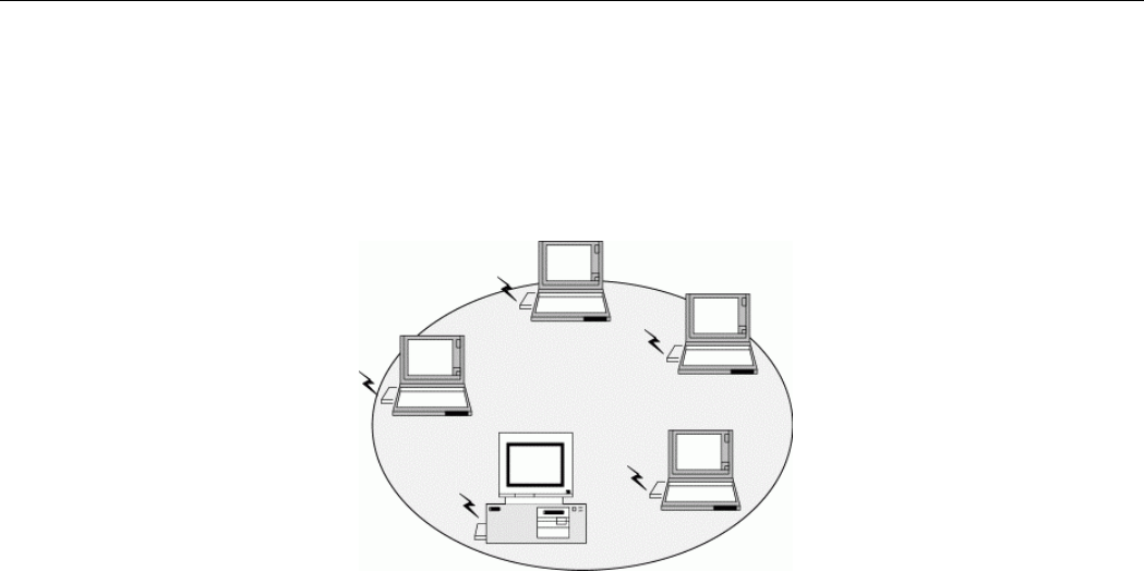
Ad-Hoc Mode
The Ad-Hoc Group offers peer-to-peer connections between workstations, allowing
communication between computers within range that have an 802.11g DSSS compatible PC
card installed. A wireless Ad-Hoc network can also access a wired LAN’s TCP/IP service
(such as e-mail and the Internet) by using a TCP/IP software router on an Ethernet equipped
PowerBook or notebook.
Figure 1-1 Ad-Hoc Mode
54Mbps 802.11g Wireless LAN Card
4
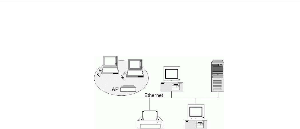
Infrastructure Mode
The Infrastructure network uses an AP or several APs as a gateway, linking the wireless
network to a wired LAN. As a result, portable workstations or desktops on your wireless
network have access to all of the features of your wired LAN including e-mail, Internet access,
network printers and files server.
Figure 1-2 Infrastructure Mode
Chapter 1 Introduction
5
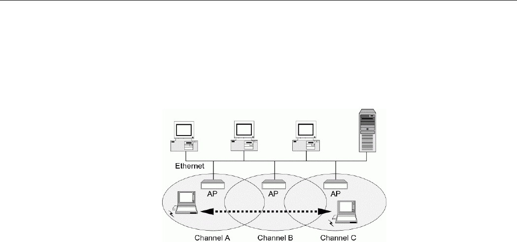
Roaming
Multiple Access Points can be installed to extend the wireless service coverage area for
seamless wireless access. Within an extended service area, all Access Points and wireless
clients must have the same Service Set Identity (SSID). Roaming among different Access
Points is controlled automatically to maintain the wireless connectivity at all times.
Figure 1-3 Roaming Across Multiple Access Points
7
Chapter 2 Installing the Wireless LAN Card
This chapter describes the installation process for the driver and software for the Wireless
LAN Card. Proper driver installation is to allow the device to operate on your host computer
while the utility software, Broadcom Wireless Configuration Utility, is to help you configure
and monitor your Wireless LAN Card.
System Requirements
To use the Wireless LAN Card, your computer must meet the following minimum
requirements:
Pentium-class PC,300MHz or better recommended
64 MB of RAM, additional memory recommended
Hard disk space at least 30 Mbytes
Windows 98(SE)/Me/2000/XP
UL listed I.T.E. computers
54Mbps 802.11g Wireless LAN Card
8
Installing Wireless LAN Driver and Software
Follow these steps to install the Wireless LAN Card driver and software:
Caution: Do not connect the Wireless LAN Card device to your computer before installing its
driver. If this happens, the Windows PnP function will detect the wireless adapter and issue a
dialog box requesting for its driver. Click Cancel to quit the wizard and unplug the Wireless
LAN Card.
1. Close all Windows programs that are running. Insert the provided Software Utility CD
into your CD-ROM drive. Run setup.exe from the Driver folder of the Software Utility
CD.
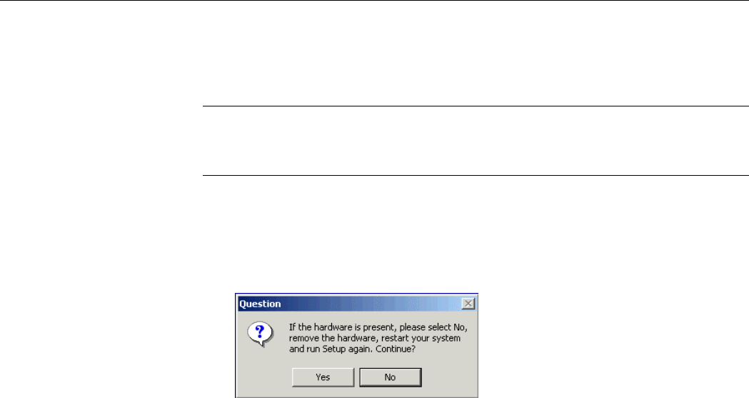
2. If the wireless adapter is not yet inserted into your computer, click Yes. Otherwise click
No to remove the device. Then restart your system and run setup.exe again.
Chapter 2 Installing the Wireless LAN Card
9
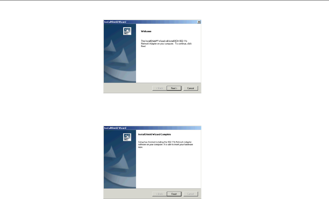
3. When the welcome screen pops up, click Next.
4. Upon hardware detection, Windows OS hardware wizard will appear requesting for the
driver. Just follow the on-screen instructions to proceed.
5. Click Finish when the following screen appears.

54Mbps 802.11g Wireless LAN Card
10
Now you are done with the installation procedure. The provided Broadcom Wireless
Configuration Utility should be launched automatically with its icon appearing on the right
side of the taskbar. Proceed to next chapter to configure or fine-tune your Wireless LAN Card
settings.
Note: If you need to set up the TCP/IP address or the subnet mask, refer to “Appendix C
Setting Up TCP/IP” for details.

11
Chapter 3 Using Broadcom Wireless Configuration Utility
Once your wireless adapter software is properly installed, the provided Broadcom Wireless
Configuration Utility is ready for use. The utility comes with six tabs. The Wireless
Networks tab allows to configure your wireless connection. The Link Status tab displays the
current link status. The Site Monitor tab allows to monitor available networks. The
Diagnostic tab allows to perform diagnostics. The utility information is displayed on the
Information tab. The Statistics tab displays the statistics and status information pertaining to
your Wireless LAN Card.
See the ensuing subsections for instructions to launch the utility and description of each tab.
Note: If you are using Windows XP, you can also use the Windows XP-included wireless
utility to configure and monitor your wireless network. For more information on using
Windows wireless utility, please refer to Windows XP on-line help.

54Mbps 802.11g Wireless LAN Card
12
Accessing Broadcom Wireless Configuration Utility
You can access the Broadcom Wireless Configuration Utility by any of the following
methods:
• Double-click the Broadcom Wireless Utility icon on the system tray and then
click Advanced.
• Right-click the tray icon and select Open Utility from its context menu.
• Under Control Panel, double-click the Broadcom Wireless Utility icon.
The Broadcom Wireless Configuration Utility screen pops up with six available tabs:
Wireless Network, Link Status, Statistics, Site Monitor, Diagnostics and Information.
Please see the appropriate section which describes each tab item.
Notice When Assessing Broadcom Utility under Windows XP
Aside from using Broadcom Wireless Configuration Utility for wireless network
configuration, Windows XP includes a Wireless Network Connection utility to configure
your wireless adapter. By default, your wireless adapter is controlled by Windows
XP-included wireless utility.
Chapter 3
13
You can choose to configure your wireless network via either the Broadcom Wireless
Configuration Utility or Windows XP-included wireless utility.
Using Broadcom Wireless Configuration Utility
To use Broadcom Wireless Configuration Utility for configuration purpose, you should
disable the Windows XP-included wireless utility by these steps:
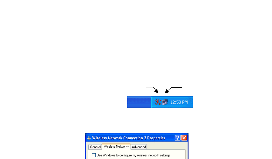
1. Double-click the Broadcom wireless icon on system tray and click the Wireless
Networks tab.
Or double-click the Windows wireless icon and then click Advanced (or Properties) >
Wireless Networks.
2. On the Wireless Networks tab, uncheck the Use Windows to configure my wireless
network settings box and click OK. This will restore the Wireless Networks tab in
Broadcom Wireless Configuration Utility.
Windows wireless icon
Broadcom wireless icon

54Mbps 802.11g Wireless LAN Card
14
Reverting back to Windows XP-included Wireless Utility
To revert back to using Windows XP-included wireless utility, double-click the Windows
wireless icon (not the Boradcom icon) and then click Advanced (or Properties). Click the
Wireless Networks tab and check the Use Windows to configure my wireless network
settings box and click OK.

Chapter 3
15
Wireless Networks Tab
Wireless Networks tab allows to do the following task:
• Connecting to an Existing Wireless Network
• Configuring a New Wireless Network Connection
• Specifying a Network Type to Access
See the appropriate subsection according to your need.
Connecting to an Existing Wireless Network
To connect to an existing Access Point/Wireless LAN Card, take the following steps:
1. Double-click the Broadcom Wireless Utility icon on the system tray.
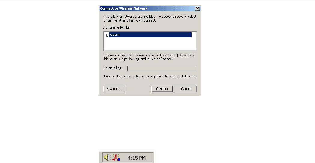
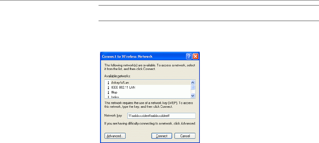
2. When the Connect to Wireless Network window pops up, you will see all the wireless
networks available in the air. Under Available networks, select the wireless network
you want to connect to.
54Mbps 802.11g Wireless LAN Card
16
3. If the target wireless network has been set with WEP key, you must enter the same WEP
key in the Network key field. Otherwise, this field is dimmed and you do not need to set
up the WEP key.
4. Click Connect, then you will join the target network and this dialog window will
disappear. When your wireless connection is established, the connection icon may appear
as below:
Chapter 3
17
Configuring a New Wireless Network Connection
When you open the Connect to Wireless Network window, a network which does not
broadcast its network name will not appear under Available networks. To connect to an
existing network but not appear under Available networks, take the following steps:
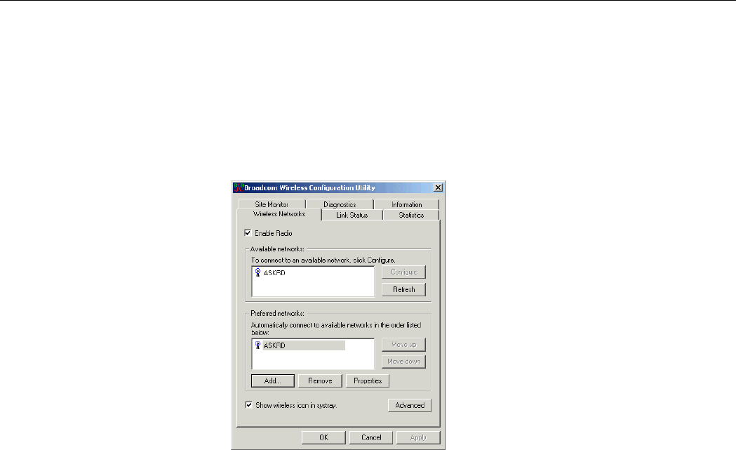
1. In Connect to Wireless Network window, click Advanced to launch the Broadcom
Wireless Configuration Utility window. Then click Add under Preferred networks
section.

54Mbps 802.11g Wireless LAN Card
18
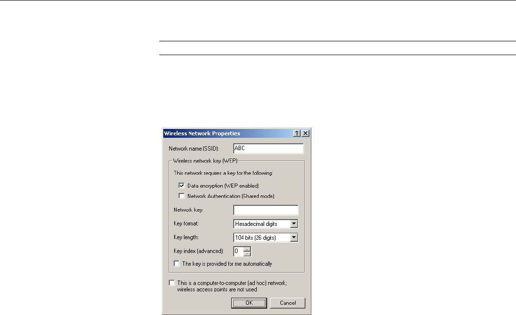
2. In the Wireless Network Properties window, configure the settings below:
Network name (SSID): Specifies the name of the Wireless LAN group you want to
participate in.
Network Authentication (Shared mode): Specifies the authentication type. You should
use the same setting as the other wireless stations in your target wireless network.
Wireless network key (WEP): If a network key is required, do the following:
• If the WEP key is automatically provided (for example, the key is stored on the
wireless network adapter given to you by your network administrator), check
The key is provided for me automatically check box.
• If the WEP key is not automatically provided for you, leave The key is provided
for me automatically check box blank and then enter the key in the Network
key field.
When entering the key, the Key format and Key length are changed automatically
according to the format and length of the characters you entered. When using
Hexadecimal format, only digits 0-9 and letters a-f, A-F are allowed. Make sure to enter
the character matching the required key format and length as below:
ASCII characters Hexadecimal digits
40 bit 5 alphanumeric characters 10 hexadecimal digits
104 bit 13 alphanumeric characters 26 hexadecimal digits
Chapter 3
19
Key index (advanced): Specifies the key index value. You can specify up to four keys
(the key index are 0, 1, 2 and 3).
Note: Contact your network administrator if you are unsure about the WEP setting.
Ad Hoc/ Infrastructure Network: If the network you are configuring is an Ad Hoc
network, check This is a computer-to-computer (ad hoc) network… check box.
Otherwise leave it unchecked for Infrastructure network connection.
3. After entering required fields, click OK to exit this window.

54Mbps 802.11g Wireless LAN Card
20
Your newly configured network will be added under Preferred networks. Your wireless
adapter will attempt to connect preferred networks in the order in which they appear in the list.
You can change the order of preferred network by selecting the network that you want to
move and clicking the Move up or Move down button.
Note that in the Preferred networks list, an Ad-hoc network can not be moved to a higher
position than an Infrastructure network. If you want to connect to Ad Hoc network only, see
“Specifying a Network Type to Access” for instructions.
Configuring an Existing Wireless Network Connection
On the Wireless Networks tab, if your target network appears under the Available networks
or Preferred networks list but you cannot connect to it, you may want to review or
reconfigure the settings. If this is the case, just select your target network and then click
Configure (for Available networks) or Properties (for Preferred networks) to open the
properties window. Then configure the settings as needed.
Chapter 3
21
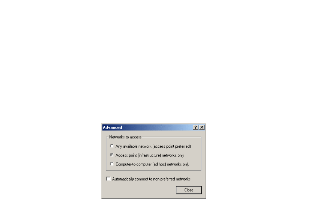
Specifying a Network Type to Access
By default, your wireless station will attempt to connect to an Infrastructure network (if
available) first. If an Infrastructure network is not available, an Ad Hoc network will then be
attempted.
However, it is possible that you want connect to certain networks only. In this situation, you
can specify the network to access by clicking the Advanced button on the Wireless Networks
tab. Then select your preferred access type and click OK.
For example, you want to connect to an Ad Hoc network but both Ad Hoc and Infrastructure
networks are available. In this case, you can select the Computer-to-computer (ad hoc)
networks only option.

54Mbps 802.11g Wireless LAN Card
22
Note that if your preferred network is limited to Access Point or Ad Hoc network, the
Preferred networks section on Wireless Networks tab will list only the networks of your
preference. If you try to add a new network of non-preferred type, the addition will not appear
in the list unless you change the preferred network types.
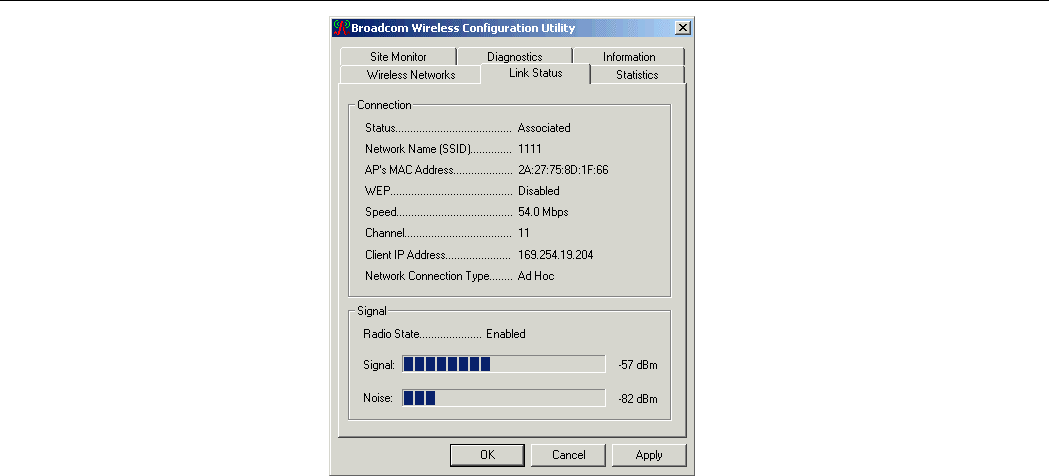
Link Status Tab
The Link Status tab contains general information about the connection and activity of your
current link.
The following table describes the items found on the Link Status screen.
Screen Item Description
Status Displays whether the card is associated with a network.
Network Name (SSID) Displays the name of the wireless network your station is
currently connected to.
AP’s MAC Address The MAC address of the associated AP.
Channel The channel your wireless station is using.
WEP Displays whether WEP is disabled or enabled in the current
wireless network.

Chapter 3
23
Screen Item Description
Speed Displays the current packet transmit rate (Mbps).
Channel Displays the channel the station is using.
Client IP Address Displays the IP address of your wireless adapter.
Network Connection Type Displays if the adapter is connected to an Access Point or Ad
Hoc network.
Radio State Displays whether the RF Signal is enabled or disabled.
Signal Displays the signal strength (dBm). On the right side, signal
strength is indicated by graphic.
Noise Displays the noise level (dBm). Noise Level reflects the level
of radio interference as measured at the Wireless LAN Card.
54Mbps 802.11g Wireless LAN Card
24
Chapter 3
25
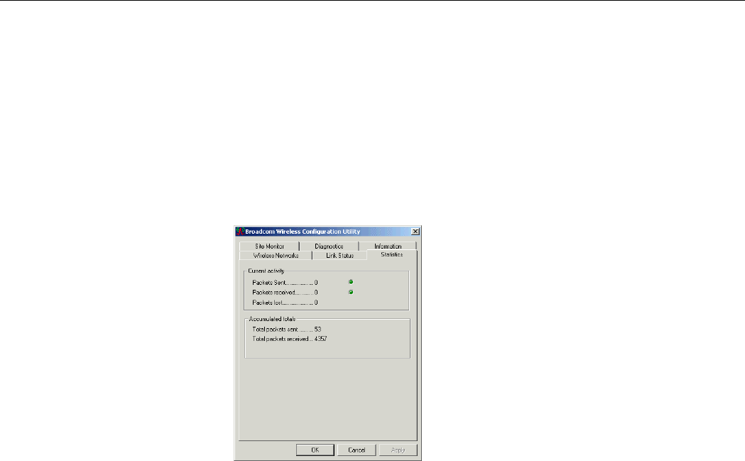
Statistics
The Statistics tab displays the current and accumulated statistics information pertaining to
your Wireless LAN Card. The following transmit and receive statistics are provided:
Packets Sent
Packets received
Packets lost
Total packets sent
Total packets received

54Mbps 802.11g Wireless LAN Card
26
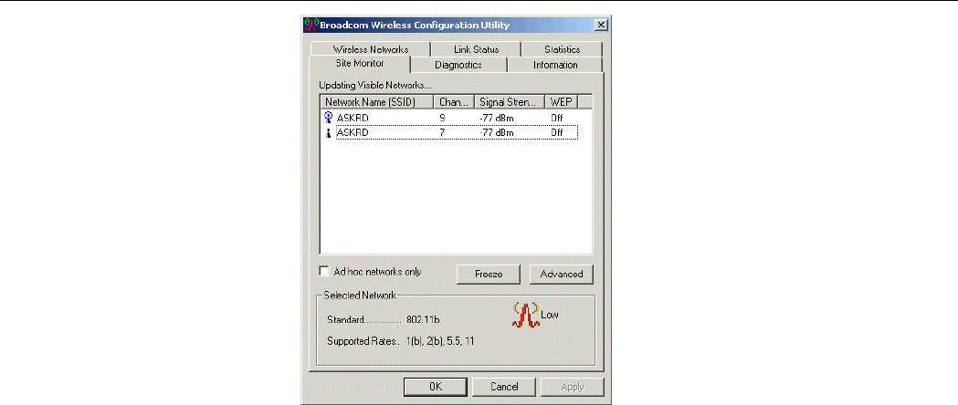
Site Monitor
The Site Monitor tab displays the general information of the wireless network available in the
air. You can use the Site Monitor feature to display the communications quality of your
computer with multiple Access Points in its vicinity. The Site Monitor allows you to conduct
a site survey to:
Determine the overall wireless coverage of your wireless network.
Optimize placement of the Access Point(s), to provide seamless connectivity to mobile
stations.
Roam throughout the wireless network environment with your station, you will be able to
identify areas that may not have adequate coverage, or that suffer from interference by
other (wireless) equipment such as microwave ovens.
The Visible Networks list will update automatically to display all visible networks.
Optionally you can click Freeze to temporarily stop the update of the list. To display only the
Ad Hoc network, check the Ad hoc networks only checkbox.
For each network, the following information will be displayed:
Field Description
Network Name (SSID) Displays the name of the wireless network your station is currently
connected to.

Chapter 3
27
Field Description
Channel The channel your wireless station is using.
Signal Strength Displays the signal strength (dBm).
WEP Displays WEP whether is disabled/enabled.
For a selected network, the following information will be displayed:
Field Description
Standard The IEEE 802.11 wireless standard.
Supported Rates The supported rates of the wireless network.
54Mbps 802.11g Wireless LAN Card
28

Chapter 3
29
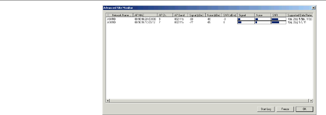
Advanced Site Monitor
Clicking the Advanced button on the Site Monitor tab brings out the Advanced Site
Monitor screen. The screen displays the following information in addition to those appear on
the Site Monitor tab:
Field Description
AP MAC The MAC address for the wireless network interface of the Access
Point.
Signal Signal level indicates the strength of the wireless signal as received
at the Wireless LAN Card. Both dBm value and graphic indicator
are displayed.
Noise (dBm) Noise Level reflects the level of radio interference as measured at
the Wireless LAN Card. Both dBm value and graphic indicator are
displayed.
SNR (dBm) The Signal-to-Noise Ratio (SNR) is the primary diagnostic counter
to diagnose wireless performance. SNR indicates the relative
strength of the received Signal Level compared to the Local Noise
Level.
In most environments, SNR is a good indicator for the quality of the
radio link between transmitter and receiver. A hi
g
her SNR value

54Mbps 802.11g Wireless LAN Card
30
Field Description
means a better quality radio link.
Both dBm value and graphic indicator are displayed.
Supported Data Rates Displays the data rates supported by the Access Point.
You can sort the list of Access Points by clicking the filed you want to use as a criteria.
You can also create log files based on the monitor measurements on the Advanced Site
Monitor screen. To create a log file, click the Start Log button and specify the path and
filename for the log file. Then the system will automatically append log entry to the file at
regular intervals until you click the Stop Log button.
Chapter 3
31

54Mbps 802.11g Wireless LAN Card
32
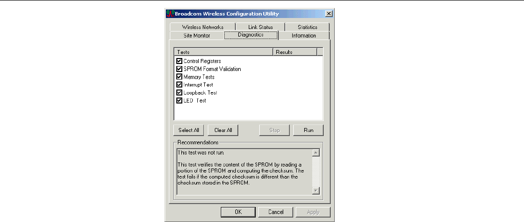
Diagnostics Tab
To perform a diagnostics, select the test you want to perform and then click Run and then
click OK if prompted. Note that by running diagnostics your network connection will be
temporarily interrupted. Connection will be resume after the completion of selected tasks.
After the selected tasks are completed, the test result (Passed or Failed) will be displayed. You
can select desired task to see detailed test information in the Status section.
The diagnostic allows to perform the following test:
Test Item Description
Control Registers This test verifies the read and write capabilities of the network
controller registers by writing various values to the registers and
verifying the result. The device driver uses these registers to
perform network functions such as sending and receive
information. If the test fails, the network adapter may not work
properly.
SPROM Format
Validation
This test verifies the content of the SPROM by reading a portion of
the SPROM and computing the checksum. The test fails if the
computed checksum is different than the checksum stored in the
SPROM.
Memory Tests This tests verifies that the network controller internal memory is
functioning properly. The test writes patterned values to the
memor
y
and readin
g
back the results. The test fails if an erroneous

Chapter 3
33
Test Item Description
value is read back. The network controller will not function without
its internal memory.
Interrupt Test This tests verifies that the network controller internal memory is
functioning properly. The test writes patterned values to the
memory and reading back the results. The test fails if an erroneous
value is read back. The network controller will not function without
its internal memory.
Loopback Test This test verifies that the NDIS driver is able to receive interrupts
from the network controller.
LED Test This test verifies that your 802.11 wireless networking hardware is
functioning correctly. This test is applicable to PC Card only.
54Mbps 802.11g Wireless LAN Card
34
Chapter 3
35
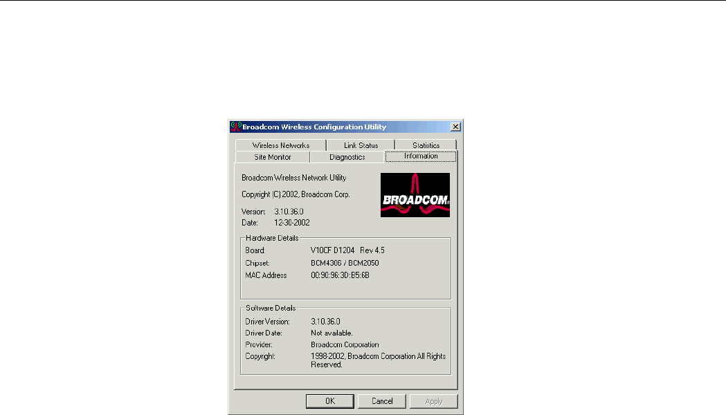
Information Tab
The Information tab displays the basic information about the device, including the hardware
and software details.

37
Chapter 4 Windows XP Wireless Zero Configuration Utility
Windows XP provides built-in Wireless Zero Configuration utility for wireless
configuration and monitoring. You can choose to configure your wireless network via either
the Wireless Client Manager as described in preceding section, or to use the Windows XP
Wireless Zero Configuration utility.
This section only provides the essential instructions on using Windows XP wireless utility to
get your wireless network established. For more information please refer to Windows XP
on-line help.
Connecting to an Access Point or Wireless LAN Card
To connect to an existing Access Point/Wireless LAN Card, take out the following steps:
1. Right-click the Wireless Connection icon on the system tray and select View Available
Wireless Networks from the context menu.
54Mbps 802.11g Wireless LAN Card
38
Note: Depending on whether your wireless network is established, the context menu may
come with different items.
2. When the Connect to Wireless Network window pops up, you will see all the Access
Points or Wireless LAN Cards that are available in the air. Select the wireless network
you want to connect to .
Figure 3-4 Windows XP Configuration Utility-Connect to Wireless Network
3. If the target Access Point/Wireless LAN Card has been set with WEP key, you must
enter the same WEP key in the Network key field. Otherwise, leave it blank.

Chapter 4 Windows XP Wireless Zero Configuration Utility
39
4. Click Connect, then you will join the target network and this dialog window will
disappear. When your wireless connection is established, the connection icon appears as
below:
Note: If the wireless connection can’t be established, double-click the connection icon and
then click Properties. Go to Authentication tab first to make sure that you use the correct
authentication type for the Wireless LAN Card. For more information, refer to
“Authentication” on page 45.
Viewing Wireless Connection Status
After you successfully connect to the Access Point or Wireless LAN Card, double-click the
icon in the system tray again. This will open the Wireless Network Connection Status
window where you can see the general data of the Wireless LAN Card, such as Status,
Duration, Speed, Signal Strength, etc.

54Mbps 802.11g Wireless LAN Card
40
Figure 3-5 Windows XP- Connection Status
Configuring Your Wireless Properties
To configure your wireless properties, open the Wireless Network Connection Status
window as described above, and then click the Properties button. This will open the Wireless
Network Connection Properties window which allows you to configure more detailed items
of the Wireless LAN Card. The following describes each tab of the properties window to help
you do more settings of the Wireless LAN Card.
Chapter 4 Windows XP Wireless Zero Configuration Utility
41
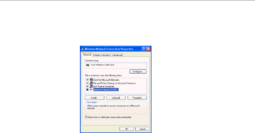
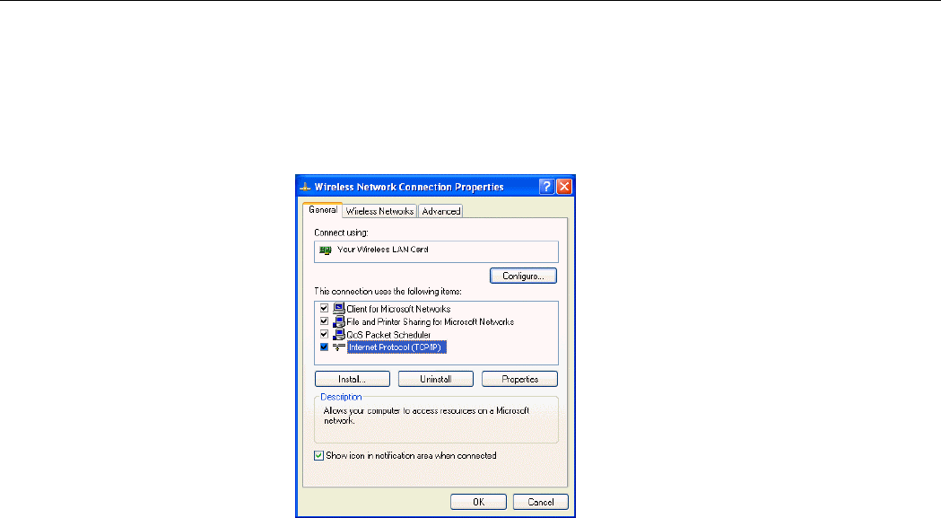
General
This tab allows you to specify the network methods to be used with your Wireless LAN Card.
The network policy depends on your wireless network. For TCP/IP protocol, you should
configure its properties as instructed by your network administrator. For more information on
TCP/IP setting, please refer to “Appendix C Setting Up TCP/IP” on page 57.
Figure 3-6 Windows XP Connection Properties -General
54Mbps 802.11g Wireless LAN Card
42
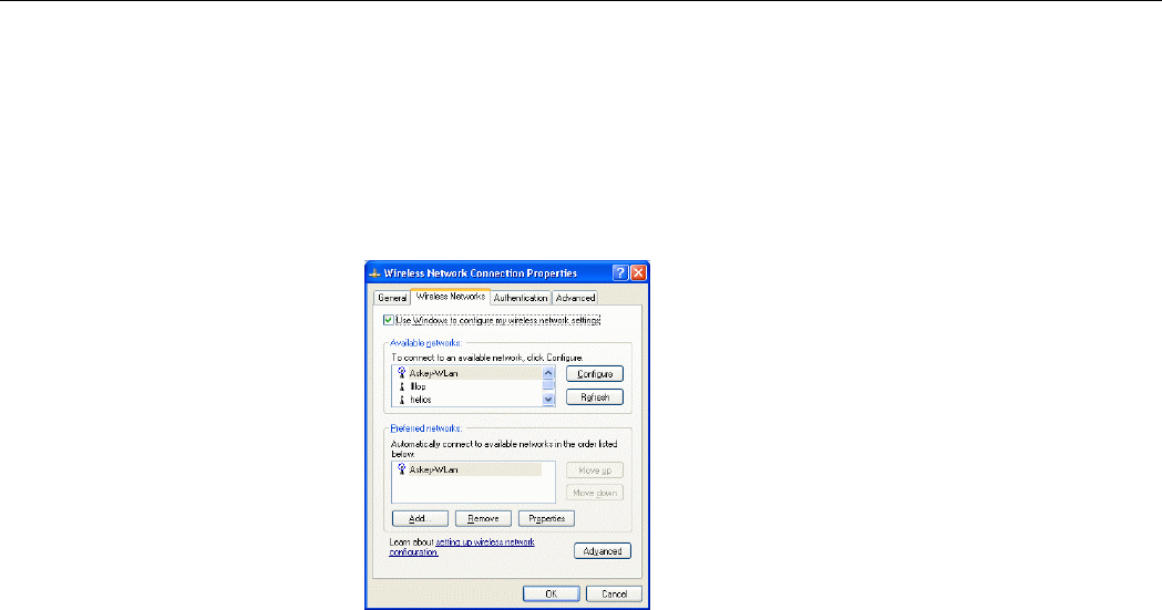
Wireless Networks
This tab contains two sections: Available networks and Preferred networks described as
below.
Under Available networks section, you can also see all the Access Points and Wireless LAN
Cards available in the air. Clicking Refresh will update the list of Access Points and Wireless
LAN Cards.
Figure 3-7 Windows XP Connection Properties-Wireless Networks
Chapter 4 Windows XP Wireless Zero Configuration Utility
43
Under Preferred networks section, you can add any wireless networks that you wish to
connect to. To do this, just click Add to add more Access Points or Wireless LAN Cards to
the list.
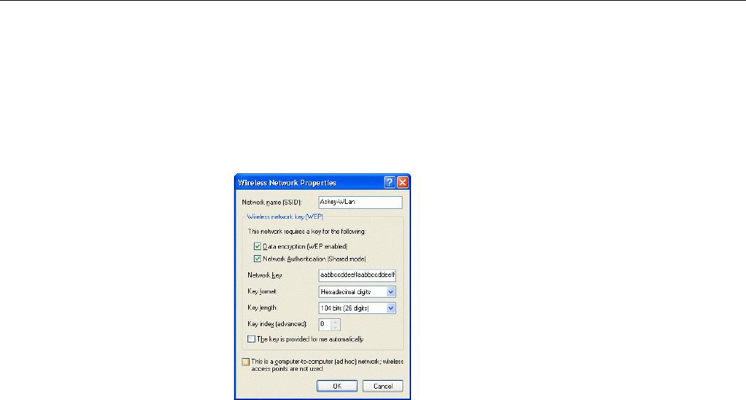
After you click the Add button, the Wireless Network Properties window pops up. Type
your network name (SSID) and, if needed, the wireless network WEP settings. Once the
Access Point or Wireless LAN Card that you want to connect to has been set with WEP key,
you must type the same WEP key as the Access Point’s or Wireless LAN Card’s.
Figure 3-8 Windows XP-Add Preferred Networks

54Mbps 802.11g Wireless LAN Card
44
After you add several profiles into Preferred networks, you can change the order in which
connection attempts to preferred networks are made. Just select the target wireless network
and click Move up or Move down to move it to a desired position.
To Access Certain Wireless Network Only
If you just want to access certain wireless network type, click the Advanced button on the
Wireless Networks tab (Figure 3-12) to open the Advanced window. You can choose to
connect to the following networks:
• Any available network ( access point preferred)
• Access point (infrastructure)
• Computer-to-computer (Peer-to-Peer Group)
The default network type is Any available network ( access point preferred). In this
network type, your device will connect to any Access Points or Wireless LAN Cards available
in the air but Access Point always demands higher connection attempt priority.
Once you finish the advanced setting, your wireless station will then connect to your desired
network and the connected network will be listed under Available networks.

Chapter 4 Windows XP Wireless Zero Configuration Utility
45
Figure 3-9 Windows XP Configuration Utility-Set up Network to Aceess
Authentication
This tab allows you to configure the authentication settings of your Wireless LAN Card. The
most important setting for the Wireless LAN Card is to disable Enable network access
control using IEEE802.1X to ensure successful connection between the Wireless LAN Cards
and Access Points or other Wireless LAN Cards. You must disable this function for any
reason. Otherwise, there may be some problems happening during connection. For other
settings, we recommend you keep the default settings to minimize the problems during
connection.

54Mbps 802.11g Wireless LAN Card
46
Figure 3-10 Windows XP Connection Properties -Authentication
Make sure to clear the Enable
network access control using
IEEE802.1X check box to ensure
successful connection.
47
Chapter 7 Troubleshooting
Radio Interference
You may be able to eliminate any interference by trying the following:
• Reseat the Wireless LAN Card.
• Increase the distance between the wireless computers and the device causing the
radio interference.
• Plug the computer equipped with the Wireless LAN Card into an outlet on a
different branch circuit from that used by the affecting device.
• Consult the dealer or an experienced radio technician for help.
• Keep the computer with the Wireless LAN Card away from the microwave oven
and large metal objects.

54Mbps 802.11g Wireless LAN Card
48
Card Not Detected
If the Wireless LAN Card is not detected by Windows, try the following:
• Make sure the Wireless LAN Card is properly inserted in the computer.
• For PC Card, make sure the slot in your computer is working.
• Contact your dealer for additional testing if there is a hardware problem with the
Wireless LAN Card.
Cannot Connect to Another Wireless LAN Card
If you cannot make a connection to another Wireless LAN Card from your computer, it could
be due to one of the following reasons:
• Incorrect SSID. Make sure the SSID is the same for all computers that have a
Wireless LAN Card.
• Changes are not being recognized by your computer. Restart your computer.
• If in Ad-Hoc mode, make sure the Log on to Windows NT domain check box is
not selected in the Client for Microsoft Networks Properties dialog box in the
Network Configuration tab.
• Incorrect IP Address or Subnet Mask. Check these settings in the TCP/IP
Properties dialog box in the Network Configuration tab.

Chapter 7 Troubleshooting
49
Poor Link Quality
If the Link Quality display stays in the Poor range, it could be due to one of the following
reasons:
• Radio interference.
• Distance between Wireless LAN Card and Access Point is too far. Decrease the
distance between the Wireless LAN Card and Access Point (or another card).
Cannot Connect to Access Point
If you cannot make a connection to the Access Point, it could be due to one of the following
reasons:
• Make sure the Wireless LAN Card and Access Point have no physical connection
problems.
• Make sure the SSID for the Wireless LAN Card is the same as the Access Point.
• Make sure the privacy type is the same as that of Access Point. Also, make sure the
Default Key is the same for both computers.

54Mbps 802.11g Wireless LAN Card
50
51
Appendix A Limited Warranty
Wireless LAN Hardware
The seller warrants to the end user (“Customer”) that this hardware product will be free from
defects in workmanship and materials, under normal use and service, for 1 year from the date
of purchase from the seller or its authorized reseller. The seller’s sole obligation under this
express warranty shall be, at the seller’s option and expense, to repair the defective product or
part, deliver to Customer an equivalent product or part to replace the defective item, or if
neither of the two foregoing options is reasonably available, The seller may, in its sole
discretion, refund to the Customer the purchase price paid for the defective product. All
products that are replaced will become the property of the seller. Replacement products may
be new or reconditioned.

54Mbps 802.11g Wireless LAN Card
52
Wireless LAN Software
The seller warrants to Customer that each software program licensed from it , except as noted
below, will perform in substantial conformance to its program specifications, for a period of 1
year from the date of purchase from the seller or its authorized reseller. The seller warrants the
media containing software against failure during the warranty period. No updates are provided.
The seller’s sole obligation under this express warranty shall be, at the seller’s option and
expense, to refund the purchase price paid by Customer for any defective software product, or
to replace any defective media with software which substantially conforms to applicable seller
published specifications. Customer assumes responsibility for the selection of the appropriate
application programs and associated reference materials. The seller makes no warranty or
representation that its software products will meet Customer’s requirements or work in
combination with any hardware or software applications products provided by third parties,
that the operation of the software products will be uninterrupted or error free, or that all
defects in the software products will be corrected. For any third party products listed in the
seller software product documentation or specifications as being compatible, the seller will
make reasonable efforts to provide compatibility, except where the non-compatibility is
caused by a defect in the third party’s product or from use of the software product not in
accordance with the seller’s published specifications or user manual.
53
Appendix B Regulatory Compliance
FCC Part 15 Declaration of Conformity (DoC)
The following equipment:
Product Name: Wireless LAN Card
is herewith confirmed to comply with the requirements of FCC Part 15 rules. The operation is
subject to the following two conditions:
1. This device may not cause harmful interference, and
2. This device must accept any interference received, including interference that may cause
undesired operation.

54Mbps 802.11g Wireless LAN Card
54
FCC Rules and Regulations - Part 15
Warning: This device has been tested and found to comply with the limits for a Class B digital device
pursuant to Part 15 of the Federal Communications Commissions Rules and Regulation. These limits are
designed to provide reasonable protection against harmful interference when the equipment is operated
in a commercial environment. This equipment generates, uses, and can radiate radio frequency energy
and, if not installed and used in accordance with the instruction manual, may cause harmful interference
to radio communications.
However, there is no guarantee that interference will not occur in a particular installation. If this
equipment does cause harmful interference to radio or television reception, which can be determined by
turning the equipment off and on, the user is encouraged to try and correct the interference by one or
more of the following measures:
• Relocate your WLAN equipped laptop computer.
• Increase the separation between the WLAN equipped laptop computer and other electronics.
• Connect the WLAN equipped laptop computer into an outlet on a circuit different from that
of other electronics.
• Consult the dealer or an experienced radio/TV technician for help.

Appendix C Setting Up TCP/IP
55
FCC Radiation Exposure Statement
This equipment complies with FCC radiation exposure limits set forth for an uncontrolled
environment. This equipment should be installed and operated with minimum distance of
20cm between the radiator & your body.
This transmitter must not be co-located or operating in conjunction with any other antenna or
transmitter.
FCC Caution:
Any changes or modifications not expressly approved by the party responsible for compliance
could void the user's authority to operate this equipment.
This device is intended only for OEM integrators under the following conditions:
1) The antenna must be installed such that 20 cm is maintained between the antenna and
users, and
2) The transmitter module may not be co-located with any other transmitter or antenna.
As long as 2 conditions above are met, further transmitter test will not be required.
However, the OEM integrator is still responsible for testing their end-product for any
additional compliance requirements required with this module installed (for example,
digital device emissions, PC peripheral requirements, etc.).

54Mbps 802.11g Wireless LAN Card
56
IMPORTANT NOTE:
In the event that these conditions can not be met (for example certain laptop configurations or
co-location with another transmitter), then the FCC authorization is no longer considered
valid and the FCC ID can not be used on the final product. In these circumstances, the OEM
integrator will be responsible for re-evaluating the end product (including the transmitter) and
obtaining a separate FCC authorization.
End Product Labeling
This transmitter module is authorized only for use in device where the antenna may be
installed such that 20 cm may be maintained between the antenna and users (for example:
This module will be bundling into Broadband product such as Wireless ADSL/Wireless
Router or AP/Wireless Cable Modem/ Notebook with antenna mounted around LCD panel).
The final end product must be labeled in a visible area with the following: “Contains TX FCC
ID: Q87-CGV2W”.
Manual Information That Must be Included
The OEM integrator has to be aware not to provide information to the end user regarding how
to install or remove this RF module in the users manual of the end product which integrate
this module.
The users manual for OEM integrators must include the following information in a prominent
location “ IMPORTANT NOTE: To comply with FCC RF exposure compliance requirements,
the antenna used for this transmitter must be installed to provide a separation distance of at
least 20 cm from all persons and must not be co-located or operating in conjunction with any
other antenna or transmitter.

Appendix C Setting Up TCP/IP
57
Appendix C Setting Up TCP/IP
This section contains instructions for configuring the TCP/IP protocol of the Wireless LAN
Card. The IP address policy depends on your wireless network. You should configure your
TCP/IP protocol as instructed by your network administrator.
For Windows 98/ME
1. Double-click the Network icon on the Control Panel.
2. Click the Configuration tab of the Network dialog box.
3. In the network components list, select the TCP/IP protocol of your Wireless LAN Card,
e.g., TCP/IP ->Broadcom 802.11g Network Adapter and then click Properties.

54Mbps 802.11g Wireless LAN Card
58
4. On the IP Address tab, choose one of the methods as required:
Option A: Click Specify an IP address.
In the IP Address box, enter a valid four-component IP address, either a public or
private one as required.
In the Subnet Mask box, enter a valid four-component IP address.
Then select the Gateway tab and enter your gateway information.
Option B: Select Obtain an IP address automatically.
Then an IP address will be automatically assigned to your computer.
5. Click OK to return to Network dialog box and click OK again to finish configuration. If
your TCP/IP properties have been modified, you will be prompted to restart your
computer. Click Yes to have new settings take effect.
Appendix C Setting Up TCP/IP
59
For Windows 2000/XP
1. Double-click Network Dial-up Connections (Windows 2000) or Network Connections
(Windows XP) on Control Panel.
2. Right-click the Local Area Connection icon corresponding to your wireless adapter
(e.g., Broadcom 802.11g Network Adapter) and click Properties.

54Mbps 802.11g Wireless LAN Card
60
3. On the General tab, highlight Internet Protocol (TCP/IP) and then click Properties.
Option A: Use fixed IP address.
Enable the Use the following IP Address option. Enter the IP address, Subnet Mask
and Default gateway. Then click OK.
Option B: Use dynamic IP address
Select Obtain an IP address automatically.
4. Close the Local Area Connection Properties window. For Windows 2000, if prompted,
click Yes to restart your computer.

Appendix C Setting Up TCP/IP
61

63
Appendix D Specifications
Host Interfaces Mini PCI
Form factor Type III B
Chipset Broadcom BCM 4306 & BCM 2050
Operation Voltage 3.3VDC
Network Standards IEEE 802.11b (Wi-Fi™) standard and IEEE 802.11g standard (54G)
Modulation Techniques DBPSK,DQPSK,CCK,16QAM,64QAM
Modulation Technology OFDM,DSSS
Data Rate 802.11b: 11, 5.5, 2, 1 Mbps
802.11g: 54, 48, 36, 24, 18, 12, 9, 6 Mbps
Network Architectures Infrastructure and Ad Hoc
Operating Frequencies 2.4-2.497 GHz
Operating Channels 802.11b: 11 for North America, 14 for Japan, 13 for Europe (ETSI)
802.11g: 13 for North America, 13 for Europe (ETSI), 13 for Japan
RF Output Power 15 dBm maximum output power (14 dBm nominal ± 1 dBm over operating
temperature
Receiver sensitivity
(PER <10%) -80dBm @ 6Mbps
Antenna Type Hardware diversity support: transmit and receive on Main and Auxiliary antenna

54Mbps 802.11g Wireless LAN Card
64
connectors.
Range
802.11b: 11 Mbps up to 180m LOS, 60m indoors; 1 Mbps up to 570m LOS,
125m indoors
802.11g: 54 Mbps up to 50m LOS, 20m indoors; 18 Mbps up to 150m LOS, 75m
indoors
Power Consumption Tx peak: 550 ma @ 3.3VDC; Rx peak: 350 ma @ 3.3VDC;
Idle: 225mA @ 3.3VDC
Security Hardware 64/128-bit WEP engine; WEP weak-key avoidance, TKIP, hardware
AES engine supporting CCM and OCB, 802.1x, SSN
Delay Tolerance 802.11b: Multipath R.M.S Delay Spread @ 1% FER: 11 Mbps > 250 nsec; 5.5
Mbps > 300 nsec
Client Utility Automatic location profile, site monitor, current link status, and diagnostics
Software Support Microsoft WHQL certified for Windows XP, 2000, and ME. Linux and VxWorks
embedded drivers.
LED Indicators WLAN Activity Monitor, WLAN Radio Status Indicators
Switch Manual radio on/off disables transmit and receive to comply
with aviation in-flight restrictions
Temperatures Operates from 0 to 70 ℃
Storage from -40 to 90 ℃
Humidity (non-condensing) 5 to 95%
Certifications
Wi-Fi; FCC part 15C/15.247; ETS 300 328-2; UL; IEC60950; EN 301 489-1,17;
prEN50371
;CE Mark; TELEC
65
Glossary
10BaseT An IEEE standard (802.3) for operating 10 Mbps Ethernet networks (LANs) with twisted pair
cabling and a wiring hub.
Access Point An internetworking device that seamlessly connects wired and wireless networks. Access Points
combined with a distributed system support the creation of multiple radio cells that enable
roaming throughout a facility.
Ad-Hoc A network composed solely of stations within mutual communication range of each other (no
Access Point connected).
BSS Basic Service Set. A set of stations controlled by a single coordination function.
Channel A medium used to pass protocol data units that can be used simultaneously in the same volume
of space by other channels of the same physical layer, with an acceptably low frame error ratio
due to mutual interference.
Encapsulated An Ethernet address mode that treats the entire Ethernet packet as a whole and places it inside
an 802.11 frame along with a new header.

54Mbps 802.11g Wireless LAN Card
66
ESS Extended Service Set. A set of one or more interconnected Basic Service Sets (BSSs) and
integrated Local Area Networks (LANs) can be configured as an Extended Service Set.
Ethernet The most widely used medium access method, which is defined by the IEEE 802.3 standard.
Ethernet is normally a shared media LAN; i.e., all the devices on the network segment share
total bandwidth. Ethernet networks operate at 10Mbps using CSMA/CD to run over 10BaseT
cables.
Gateway A network component that acts as an entrance to another network.
IEEE 802.11 The IEEE 802.xx is a set of specifications for LANs from the Institute of Electrical and
Electronic Engineers (IEEE). Most wired networks conform to 802.3, the specification for
CSMA/CD-based Ethernet networks or 802.5, the specification for token ring networks. 802.11
defines the standard for wireless LANs encompassing three incompatible (non-interoperable)
technologies: Frequency Hopping Spread Spectrum (FHSS), Direct Sequence Spread Spectrum
(DSSS), and Infrared. IEEE standards ensure interoperability between systems of the same type.
Infrastructure A wireless network centered about an Access Point. In this environment, the Access Point not
only provides communication with the wired network but also mediates wireless network traffic
in the immediate neighborhood.
IP Internet Protocol. The standard protocol within TCP/IP that defines the basic unit of
information passed across an Internet connection by breaking down data messages into packets,
routing and transporting the packets over network connections, then reassembling the packets at
their destination. IP corresponds to the network layer in the ISO/OSI model.

Glossary
67
IP Address An IP address is a 32-bit number that identifies each sender or receiver of information sent
across the Internet. An IP address has two parts: the identifier of a particular network on the
Internet and an identifier of the particular device (which can be a server or a workstation) within
that network.
ISP Internet Service Provider. An organization that provides access to the Internet. Small ISPs
provide service via modem and ISDN while the larger ones also offer private line hookups (T1,
fractional T1, etc.).
LAN Local Area Network. A communications network that serves users within a defined
geographical area. The benefits include the sharing of Internet access, files, and equipment, such
as printers and storage devices. Special network cabling (10BaseT) is often used to connect the
PCs together.
NAT Network Address Translation. The translation of an Internet Protocol address (IP address) used
within one network to a different IP address known within another network. One network is
designated the internal network and the other is the external. The internal network then appears
as one entity to the outside world.

54Mbps 802.11g Wireless LAN Card
68
Radio
Frequency
RF, Terms: GHz, MHz, Hz —The international unit for measuring frequency is Hertz (Hz),
equivalent to the older unit of cycles per second. One megahertz (MHz) is one Million-Hertz.
One giga hertz (GHz) is one Billion-Hertz. The standard U.S. electrical power frequency is 60
Hz, the AM broadcast radio frequency band is 0.55–1.6 MHz, the FM broadcast radio frequency
band is 88–108 MHz, and wireless 802.11 LANs operate at 2.4GHz.
SSID Service Set ID. A group name shared by every member of a wireless network. Only client PCs
with the same SSID are allowed to establish a connection.
Subnet Mask A value that defines whether your computer communicates only within your LAN or
communicates outside of your LAN, where it is routed out to the rest of the Internet. A Subnet
Mask that has the same first three components (for example, 255.255.255.0) is the routing
pattern for a Class C address.
TCP Transmission Control Protocol. The standard transport level protocol that provides the full
duplex, stream service on which many applications’ protocols depend. TCP allows a process on
one machine to send a stream of data to a process on another. Software implementing TCP
usually resides in the operating system and uses the IP to transmit information across the
network.
WEP Wired Equivalent Privacy. The optional cryptographic confidentiality algorithm specified by
802.11. The algorithm is being used to provide data confidentiality that is subjectively
equivalent to the confidentiality of a wired LAN medium that does not employ cryptographic
techniques to enhance privacy..