LINKSYS HGA5S-3 Wireless-G VPN Broadband Router User Manual Book
LINKSYS LLC Wireless-G VPN Broadband Router Book
LINKSYS >
Contents
- 1. Users Manual Part 1
- 2. Users Manual Part 2
- 3. Users Manual Part 3
- 4. Users Manual Part 4
- 5. User Manual Part 5
Users Manual Part 2
17
Chapter 5: Configuring the PCs
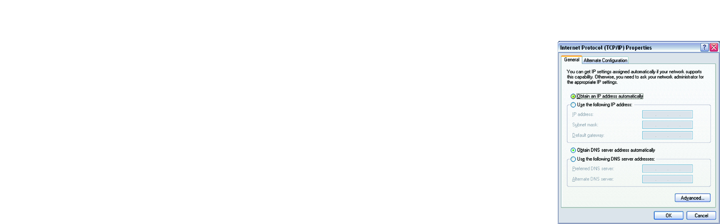
Configuring Windows XP PCs
Wireless-G VPN Broadband Router
Figure 5-8: IP Address

18
Chapter 6: Configuring the Router
Overview
Wireless-G VPN Broadband Router
Chapter 6: Configuring the Router
Overview
Linksys recommends using the Setup CD-ROM for first-time installation of the Router and setting up additional
computers. If you do not wish to run the Setup Wizard on the Setup CD-ROM, then follow the steps in this chapter
and use the Router’s web-based utility to configure the Router. This chapter will describe each web page in the
Utility and each page’s key functions. The utility can be accessed via your web browser through use of a
computer connected to the Router. For a basic network setup, most users only have to use the following screens
of the Utility:
• Basic Setup. On the Basic Setup screen, enter the settings provided by your ISP.
• Management. Click the Administration tab and then the Management tab. The Router’s default password is
admin. To secure the Router, change the Password from its default.
There are seven main tabs: Setup, Wireless, Security, Access Restrictions, Applications & Gaming,
Administration, and Status. Additional tabs will be available after you click one of the main tabs.
Setup
• Basic Setup. Enter the Internet connection and network settings on this screen.
• DDNS. To enable the Router’s Dynamic Domain Name System (DDNS) feature, complete the fields on this
screen.
• MAC Address Clone. If you need to clone a MAC address onto the Router, use this screen.
• Advanced Routing. On this screen, you can alter Network Address Translation (NAT), Dynamic Routing, and
Static Routing configurations.
• Hot Spot. Register with your Hot Spot service provider on this screen.
Wireless
• Basic Wireless Settings. You can choose your Wireless Network Mode and Wireless Security on this screen.
• Wireless Network Access. This screen displays your network access list.
Note: For added security, you should change
the password through the Administration
screen of the web-based utility.
NAT (Network Address Translation): NAT
technology translates IP addresses of a local area
network to a different IP address for the Internet.
Have You: Enabled TCP/IP on your PCs? PCs
communicate over the network with this
protocol. Refer to Appendix D: Windows Help for
more information on TCP/IP.
Note: The Router is designed to function
properly after connecting the Router to your
network. This chapter is provided solely for
those who wish to perform more advanced

19
Chapter 6: Configuring the Router
Overview
Wireless-G VPN Broadband Router
• Advanced Wireless Settings. On this screen you can access the Advanced Wireless features of Authentication
Type, Basic Data Rates, Control Tx Rates, Beacon Interval, DTIM Interval, RTS Threshold, and Fragmentation
Threshold.
Security
• Filter. To block specific users from Internet access, you can set up IP address, port, and MAC address filtering
on the Filter screen.
• VPN. To enable or disable IPSec, L2TP, and/or PPTP Pass-through, and set up VPN tunnels, use this screen.
• 802.1x. Use this screen to set up RADIUS authentication.
Access Restrictions
• Access Restriction. This screen allows you to prevent or permit only certain users from attaching to your
network.
Applications & Gaming
• Port Range Forwarding. To set up public services or other specialized Internet applications on your network,
click this tab.
• Port Triggering. To set up triggered ranges and forwarded ranges for Internet applications, click this tab.
• UPnP Forwarding. Use this screen to alter UPnP forwarding settings.
• DMZ. To allow one local user to be exposed to the Internet for use of special-purpose services, use this
screen.
Administration
• Management. On this screen, alter router access privileges and UPnP settings.
• Log. If you want to view or save activity logs, click this tab.
• Diagnostics. Use this screen to check the connection between your Router and PC.
• Factory Defaults. If you want to restore the Router’s factory defaults, then use this screen.
• Firmware Upgrade. Click this tab if you want to upgrade the Router’s firmware.
DTIM (Delivery Traffic Indication Message):
A message included in data packets that can
increase wireless efficiency.
Beacon Interval :The frequency interval of the
beacon, which is a packet broadcast by a
router to synchronize a wireless network.
RTS (Request To Send): A packet sent when a
computer has data to transmit. The computer
will wait for a CTS (Clear To Send) message
before sending data.
Fragmentation: Breaking a packet into smaller
units when transmitting over a network medium
that cannot support the original size of the
packet.
20
Chapter 6: Configuring the Router
How to Access the Web-based Utility
Wireless-G VPN Broadband Router
Status
• Router. This screen provides status information about the Router.
• Local Network. This provides status information about the local network.
How to Access the Web-based Utility
To access the web-based utility, launch Internet Explorer or Netscape Navigator, and enter the Router’s default IP
address, 192.168.1.1, in the Address field. Then press Enter.
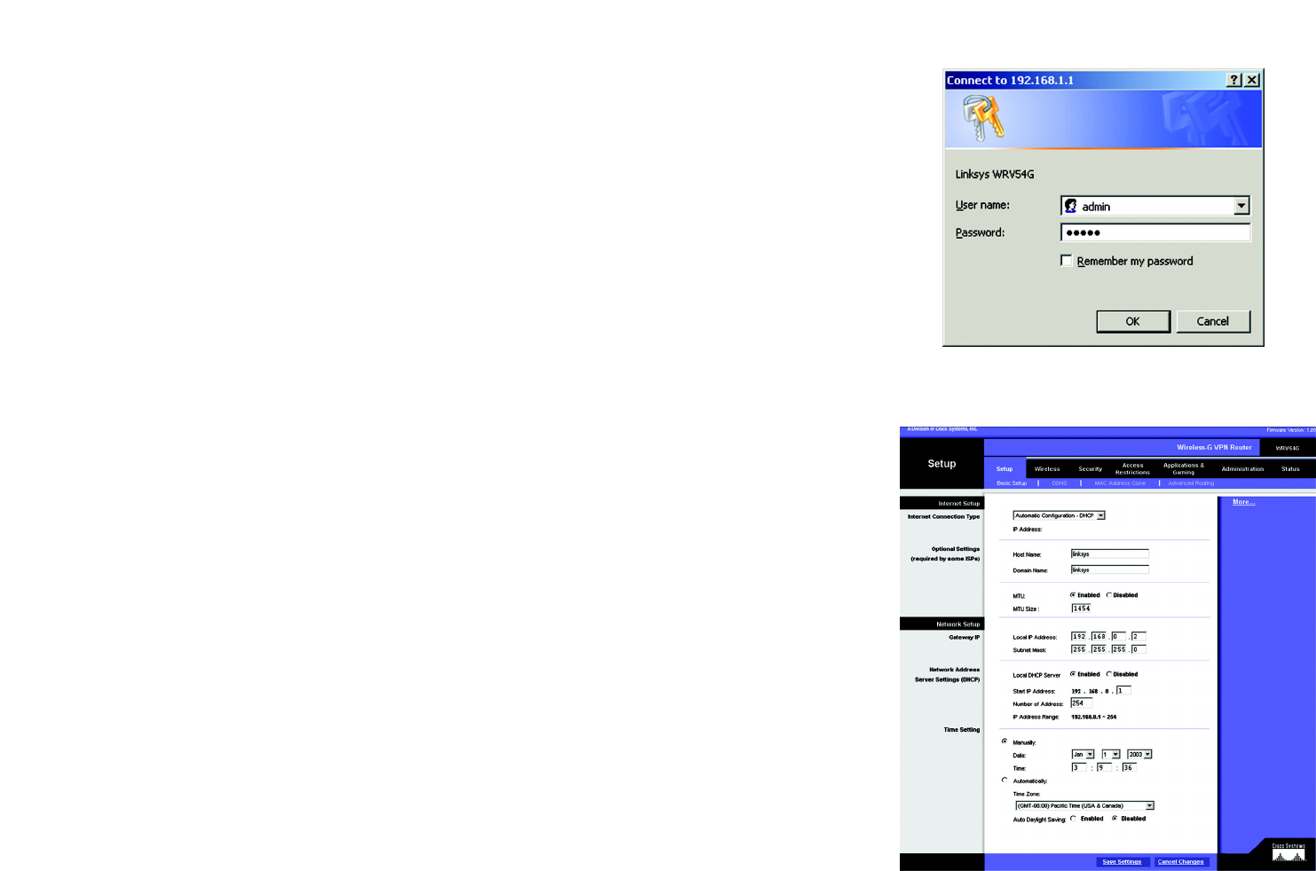
A password request page, shown in Figure 6-1 will appear. (non-Windows XP users will see a similar screen.)
Enter admin (the default user name) in the User Name field, and enter admin (the default password) in the
Password field. Then click the OK button.
The Setup Tab
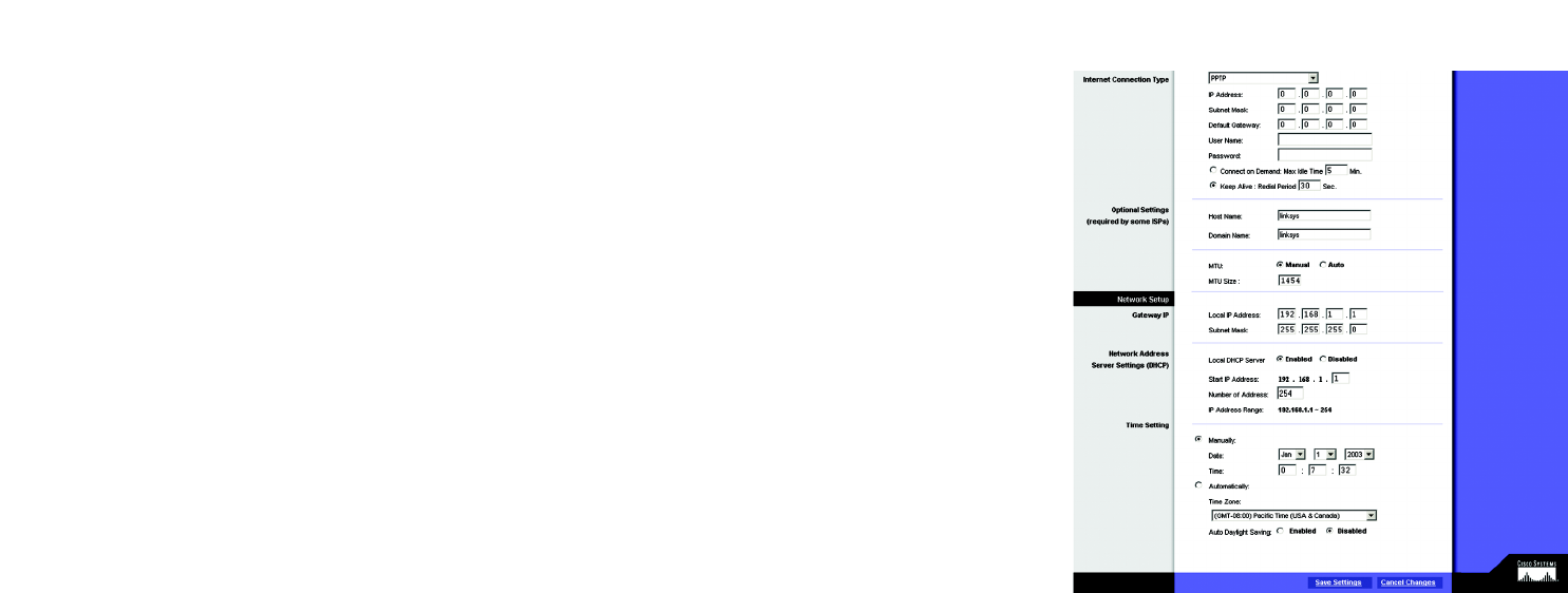
The Basic Setup Tab
The first screen that appears is the Basic Setup tab. (See Figure 6-2.) This tab allows you to change the Router's
general settings. Change these settings as described here and click the Save Settings button to save your
changes or Cancel Changes to cancel your changes.
Internet Setup
• Internet Connection Type. The Router supports four connection types: Automatic Configuration - DHCP (the
default connection type), PPPoE, Static IP, and PPTP. Each Basic Setup screen and available features will
differ depending on what kind of connection type you select.
Automatic Configuration - DHCP
By default, the Router’s Configuration Type is set to Automatic Configuration - DHCP, and it should be kept
only if your ISP supports DHCP or you are connecting through a dynamic IP address.
Figure 6-2: Setup Tab/DHCP Internet Connection Type
Figure 6-1: Password Screen

21
Chapter 6: Configuring the Router
The Setup Tab
Wireless-G VPN Broadband Router
Static (See Figure 6-3.)
If you are required to use a permanent IP address to connect to the Internet, then select Static IP.
• IP Address. This is the Router’s IP address, when seen from the WAN, or the Internet. Your ISP will provide
you with the IP Address you need to specify here.
• Subnet Mask. This is the Router’s Subnet Mask, as seen by external users on the Internet (including your
ISP). Your ISP will provide you with the Subnet Mask.
• Default Gateway. Your ISP will provide you with the Default Gateway Address, which is the ISP server’s IP
address.
• Primary DNS. (Required) and Secondary DNS (Optional). Your ISP will provide you with at least one DNS
(Domain Name System) Server IP Address.
When finished making your changes on this tab, click the Save Settings button to save these changes, or
click the Cancel Changes button to undo your changes.
PPPoE (See Figure 6-4.)
Some DSL-based ISPs use PPPoE (Point-to-Point Protocol over Ethernet) to establish Internet connections. If
you are connected to the Internet through a DSL line, check with your ISP to see if they use PPPoE. If they do,
you will have to enable PPPoE.
• User Name and Password. Enter the User Name and Password provided by your ISP.
• Connect on Demand: Max Idle Time. You can configure the Router to cut the Internet connection after it
has been inactive for a specified period of time (Max Idle Time). If your Internet connection has been
terminated due to inactivity, Connect on Demand enables the Router to automatically re-establish your
connection as soon as you attempt to access the Internet again. If you wish to activate Connect on
Demand, click the radio button. In the Max Idle Time field, enter the number of minutes you want to have
elapsed before your Internet connection terminates.
• Keep Alive Option: Redial Period. If you select this option, the Router will periodically check your Internet
connection. If you are disconnected, then the Router will automatically re-establish your connection. To
use this option, click the radio button next to Keep Alive. In the Redial Period field, you specify how often
you want the Router to check the Internet connection. The default Redial Period is 30 seconds.
When finished making your changes on this tab, click the Save Settings button to save these changes, or
click the Cancel Changes button to undo your changes.
Figure 6-3: Static Internet Connection Type
Figure 6-4: PPPoE Internet Connection Type
22
Chapter 6: Configuring the Router
The Setup Tab
Wireless-G VPN Broadband Router
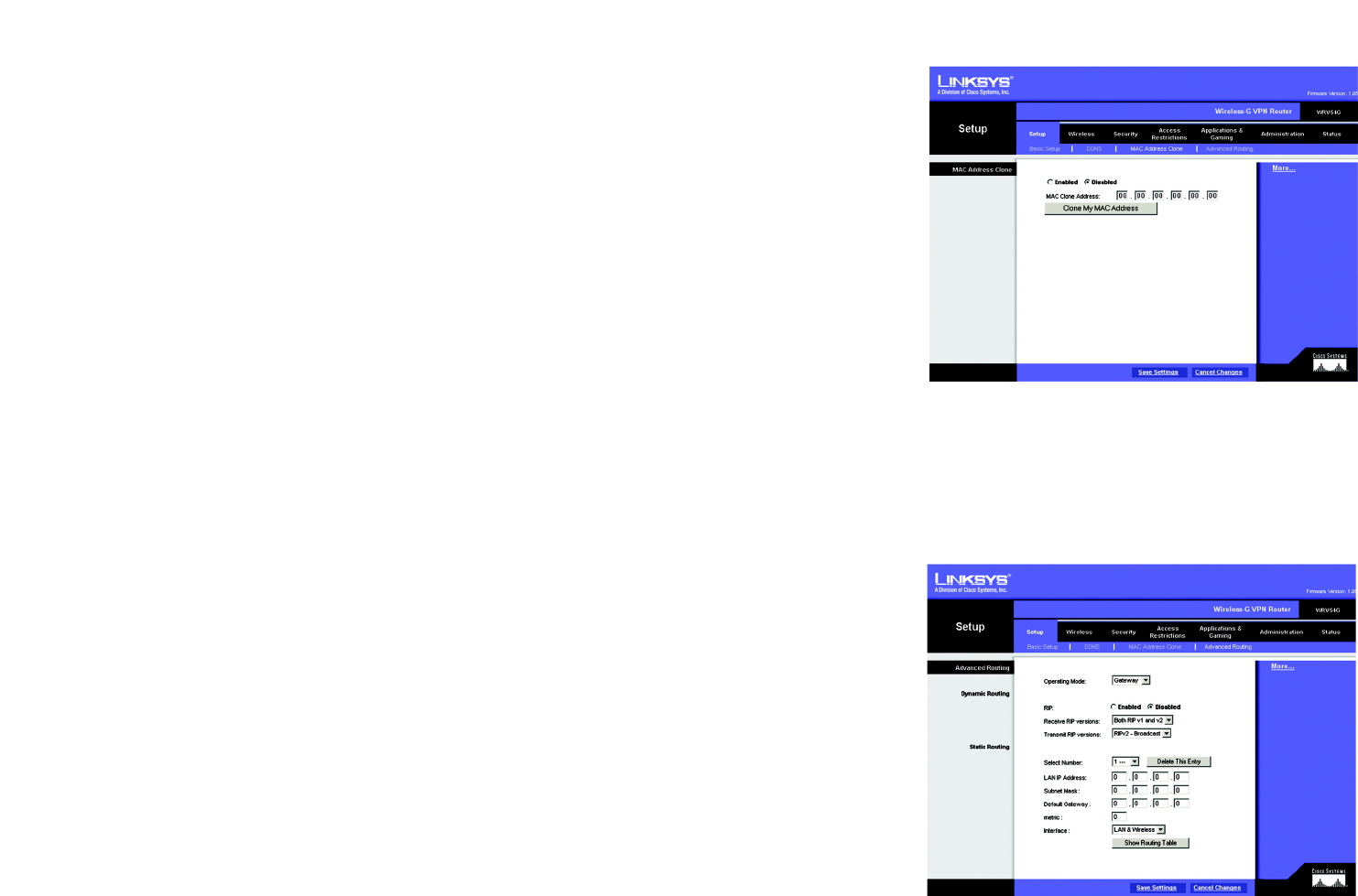
PPTP (See Figure 6-5.)
Point to Point Tunneling Protocol (PPTP) is a service that applies to connections in Europe only (see Figure 6-
8).
• Internet IP Address. This is the Router’s IP address, when seen from the Internet. Your ISP will provide you
with the IP Address you need to specify here.
• Subnet Mask. This is the Router’s Subnet Mask, as seen by external users on the Internet (including your
ISP). Your ISP will provide you with the Subnet Mask.
• Default Gateway. Your ISP will provide you with the Default Gateway Address.
• User Name and Password. Enter the User Name and Password provided by your ISP.
• Connect on Demand: Max Idle Time. You can configure the Router to cut the Internet connection after it
has been inactive for a specified period of time (Max Idle Time). If your Internet connection has been
terminated due to inactivity, Connect on Demand enables the Router to automatically re-establish your
connection as soon as you attempt to access the Internet again. If you wish to activate Connect on
Demand, click the radio button. In the Max Idle Time field, enter the number of minutes you want to have
elapsed before your Internet connection terminates.
• Keep Alive Option: Redial Period. If you select this option, the Router will periodically check your Internet
connection. If you are disconnected, then the Router will automatically re-establish your connection. To
use this option, click the radio button next to Keep Alive. To use this option, click the radio button next to
Keep Alive. In the Redial Period field, you specify how often you want the Router to check the Internet
connection. The default Redial Period is 30 seconds.
When finished making your changes on this tab, click the Save Settings button to save these changes, or
click the Cancel Changes button to undo your changes.
Optional Settings (Required by some ISPs)
• Host Name and Domain Name. These fields allow you to supply a host and domain name for the Router. Some
ISPs require these names as identification. You may have to check with your ISP to see if your broadband
Internet service has been configured with a host and domain name. In most cases, leaving these fields blank
will work.
• MTU. The MTU (Maximum Transmission Unit) setting specifies the largest packet size permitted for network
transmission. Select Enabled and enter the value desired. It is recommended that you leave this value in the
Figure 6-5: PPTP Internet Connection Type

23
Chapter 6: Configuring the Router
The Setup Tab
Wireless-G VPN Broadband Router
1200 to 1500 range. For most DSL users, it is recommended to use the value 1492. By default, MTU is set at
1500 when disabled.
Network Setup
• Gateway IP. The values for the Router’s Local IP Address and Subnet Mask are shown here. In most cases,
keeping the default values will work.
• Local IP Address. The default value is 192.168.1.1.
• Subnet Mask. The default value is 255.255.255.0.
• Network Address Server Settings (DHCP). A Dynamic Host Configuration Protocol (DHCP) server
automatically assigns an IP address to each PC on your network for you. Unless you already have one, it is
highly recommended that you leave the Router enabled as a DHCP server.
• Local DHCP Server. DHCP is already enabled by factory default. If you already have a DHCP server on your
network, set the Router’s DHCP option to Disable. If you disable DHCP, remember to assign a static IP
address to the Router.
• Start IP Address. Enter a value for the DHCP server to start with when issuing IP addresses. This value
must be 192.168.1. 2 or greater, because the default IP address for the Router is 192.168.1.1.
• Number of Address. Enter the maximum number of PCs that you want the DHCP server to assign IP
addresses to. This number cannot be greater than 253. In order to determine the DHCP IP Address range,
add the starting IP address (e.g., 100) to the number of DHCP users. By default, as shown in Figure 6-9,
add 100 to 50, and the range is 192.168.1.100 to 192.168.1.149.
• DHCP Address Range. The range of DHCP addresses is displayed here.
• Time Setting. This is where you set the time for your Router. You can set the time and date manually or
automatically, by setting the time zone.
When finished making your changes on this tab, click the Save Settings button to save these changes, or click
the Cancel Changes button to undo your changes.

24
Chapter 6: Configuring the Router
The Setup Tab
Wireless-G VPN Broadband Router
The DDNS Tab
The Router offers a Dynamic Domain Name System (DDNS) feature. DDNS lets you assign a fixed host and domain
name to a dynamic Internet IP address. It is useful when you are hosting your own website, FTP server, or other
server behind the Router.
Before you can use this feature, you need to sign up for DDNS service at one of two DDNS service providers,
DynDNS.org or TZO.com.
DDNS
DDNS Service. If your DDNS service is provided by DynDNS.org, then select DynDNS.org in the drop-down menu.
(See Figure 6-6.) If your DDNS service is provided by TZO, then select TZO.com. (See Figure 6-7.) The features
available on the DDNS screen will vary, depending on which DDNS service provider you use.
DynDNS.org
• User Name, Password, and Host Name. Enter the User Name, Password, and Host Name of the account you
set up with DynDNS.org.
• Internet IP Address. The Router’s current Internet IP Address is displayed here. Because it is dynamic, it will
change.
• Status. The status of the DDNS service connection is displayed here.
When finished making your changes on this tab, click the Save Settings button to save these changes, or click
the Cancel Changes button to undo your changes.
TZO.com Tab
• Email Address, TZO Password Key, and Domain Name. Enter the Email Address, TZO Password Key, and
Domain Name of the service you set up with TZO.
• Internet IP Address. The Router’s current Internet IP Address is displayed here. Because it is dynamic, this will
change.
• Status. The status of the DDNS service connection is displayed here.
When finished making your changes on this tab, click the Save Settings button to save these changes, or click
the Cancel Changes button to undo your changes.
Figure 6-6: DynDNS.org
Figure 6-7: TZO.com
25
Chapter 6: Configuring the Router
The Setup Tab
Wireless-G VPN Broadband Router
MAC Address Clone Tab (See Figure 6-8.)
The Router’s MAC address is a 12-digit code assigned to a unique piece of hardware for identification, like a
social security number. If your ISP requires MAC address registration, find your adapter’s MAC address by
following the instructions in “Appendix D: Finding the MAC Address and IP Address for Your Ethernet Adapter.”
MAC Clone
• MAC Clone Service. To use MAC address cloning, select Enable.
• MAC Address. To manually clone a MAC address, enter the 12 digits of your adapter’s MAC address in the on-
screen fields (see Figure 6-25). Then click the Save Settings button.
• Clone My MAC Address. If you want to clone the MAC address of the PC you are currently using to configure
the Router, then click the Clone My MAC Address button. The Router will automatically detect your PC’s
MAC address, so you do NOT have to call your ISP to change the registered MAC address to the Router’s MAC
address. It is recommended that the PC registered with the ISP is used to open the MAC Address Clone tab.
When finished making your changes on this tab, click the Save Settings button to save these changes, or click
the Cancel Changes button to undo your changes.
Advanced Routing Tab
The Advanced Routing screen allows you to configure the dynamic routing and static routing settings. (See Figure
6-9.)
Advanced Routing
• Operating Mode. Select Gateway or Router for the Operating Mode from the drop-down menu.
• Dynamic Routing. With Dynamic Routing you can enable the Router to automatically adjust to physical
changes in the network’s layout. The Router, using the RIP protocol, determines the network packets’ route
based on the fewest number of hops between the source and the destination. The RIP protocol regularly
broadcasts routing information to other routers on the network.
• Receive RIP Version To use dynamic routing for reception of network data, select the protocol you want: RIP1
or RIP2.
• Transmit RIP Version. To use dynamic routing for transmission of network data, select the protocol you want:
RIP1, RIP1-Compatible, or RIP2.
Figure 6-8: MAC Address Clone
Figure 6-9: Advanced Routing
26
Chapter 6: Configuring the Router
The Setup Tab
Wireless-G VPN Broadband Router
Static Routing
If the Router is connected to more than one network, it may be necessary to set up a static route between them.
A static route is a pre-determined pathway that network information must travel to reach a specific host or
network. To create a static route, change the following settings:
• Select Number. Select the number of the static route from the drop-down menu. The Router supports up to
20 static route entries.
• Delete This Entry. If you need to delete a route, select its number from the drop-down menu, and click the
Delete Entry button.
• LAN IP Address. The LAN IP Address is the address of the remote network or host to which you want to assign
a static route. Enter the IP address of the host for which you wish to create a static route. If you are building a
route to an entire network, be sure that the network portion of the IP address is set to 0. For example, the
Router’s standard IP address is 192.168.1.1. Based on this address, the address of the routed network is
192.168.1, with the last digit determining the Router’s place on the network. Therefore you would enter the IP
address 192.168.1.0 if you wanted to route to the Router’s entire network, rather than just to the Router.
• Subnet Mask. The Subnet Mask (also known as the Network Mask) determines which portion of an IP address
is the network portion, and which portion is the host portion. Take, for example, a network in which the
Subnet Mask is 255.255.255.0. This determines (by using the values 255) that the first three numbers of a
network IP address identify this particular network, while the last digit (from 1 to 254) identifies the specific
host.
• Default Gateway. This IP address should be the IP address of the gateway device that allows for contact
between the Router and the remote network or host.
• metric. This determines the maximum number of steps between network nodes that data packets will travel.
A node is any device on the network, such as PCs, print servers, routers, etc.
• Interface. Select LAN & Wireless or Internet, depending on the location of the static route’s final destination.
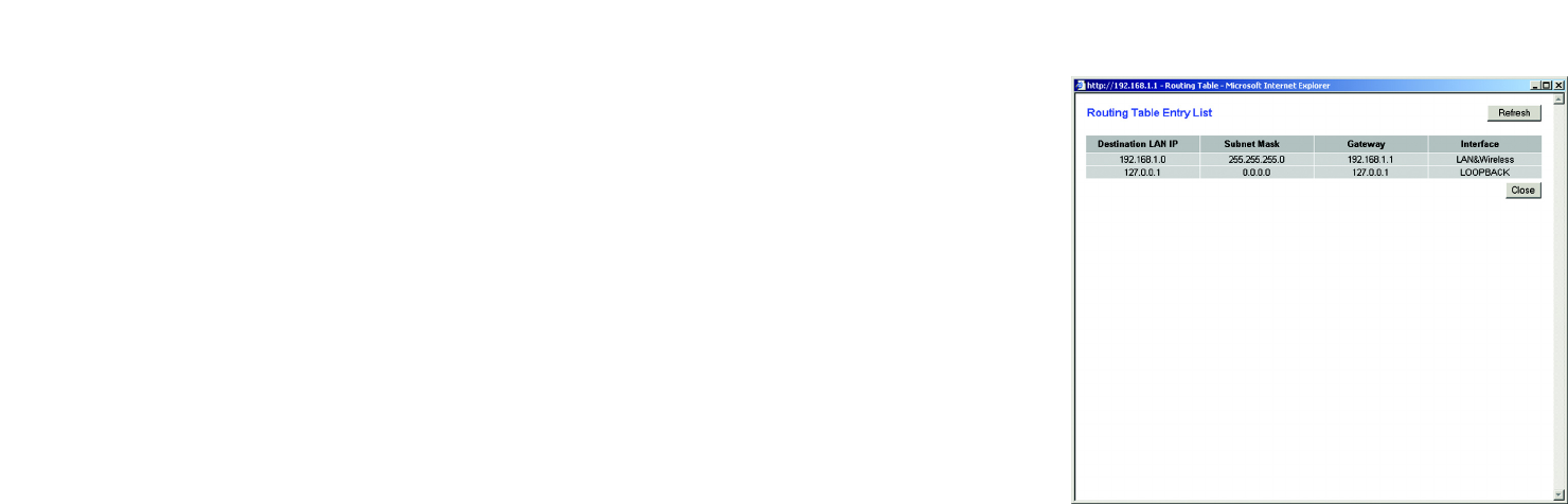
• Show Routing Table. Click the Show Routing Table button to open a screen displaying how data is routed
through your LAN. For each route, the Destination LAN IP address, Subnet Mask, Default Gateway, and
Interface are displayed. Click the Refresh button to update the information. See Figure 6-10.
When finished making your changes on this tab, click the Save Settings button to save these changes, or click
the Cancel Changes button to undo your changes.
Figure 6-10: Routing Table
27
Chapter 6: Configuring the Router
The Wireless Tab
Wireless-G VPN Broadband Router
The Wireless Tab
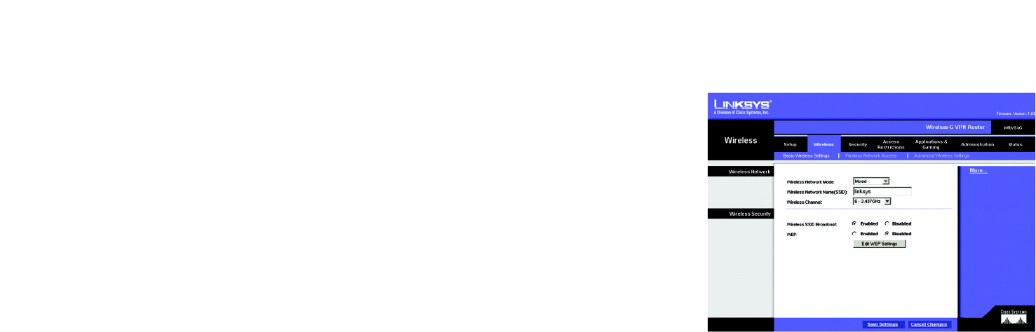
Basic Wireless Settings (See Figure 6-11.)
This screen allows you to choose your wireless network mode and wireless security.
Wireless Network
• Wireless Network Mode. If you have Wireless-G and 802.11b devices in your network, then keep the default
setting, Mixed. If you have only Wireless-G devices, select G-Only. If you want to disable wireless
networking, select Disable.
• Wireless Network Name. Enter the Wireless Network Name (SSID) into the field. The SSID is the network
name shared among all devices in a wireless network. The SSID must be identical for all devices in the
wireless network. It is case-sensitive and must not exceed 32 alphanumeric characters, which may be any
keyboard character. For added security, Linksys recommends that you change the default SSID (linksys) to a
unique name of your choice.
• Wireless Channel. Select the appropriate channel from the list provided to correspond with your network
settings, between 1 and 11 (in North America). All devices in your wireless network must use the same
channel in order to function correctly.
Figure 6-11: Basic Wireless

28
Chapter 6: Configuring the Router
The Wireless Tab
Wireless-G VPN Broadband Router
Wireless Security
• Wireless SSID Broadcast. When wireless clients survey the local area for wireless networks to associate with,
they will detect the SSID broadcast by the Router. To broadcast the Router's SSID, keep the default setting,
Enabled. If you do not want to broadcast the Router's SSID, then select Disabled.
• WEP. An acronym for Wired Equivalent Privacy, WEP is an encryption method used to protect your wireless
data communications. WEP uses 64-bit or 128-bit keys to provide access control to your network and
encryption security for every data transmission. To decode data transmissions, all devices-Wireless-G and
802.11b-in a network must use an identical WEP key. Higher encryption levels offer higher levels of security,
but due to the complexity of the encryption, they may decrease network performance. To enable WEP
encryption, click the Enabled radio button. Then click the Edit WEP Settings button to configure the WEP
settings. To disable WEP encryption, keep the default setting, Disabled.
WEP (See Figure 6-12.)
The WEP screen allows you to configure your WEP settings. WEP encryption should always be enabled to
increase the security of your wireless network. Default Transmit Key Select which WEP key (1-4) will be used
when the Router sends data. Make sure the receiving device is using the same key.
• WEP Encryption. Select the level of WEP encryption you wish to use, 64-bit 10 hex digits or 128-bit 26 hex
digits. Higher encryption levels offer higher levels of security, but due to the complexity of the encryption,
they may decrease network performance.
• Passphrase. Instead of manually entering WEP keys, you can enter a Passphrase. This Passphrase is used to
generate one or more WEP keys. It is case-sensitive and should not be longer than 16 alphanumeric
characters. (This Passphrase function is compatible with Linksys wireless products only. If you want to
communicate with non-Linksys wireless products, enter the WEP key manually on the non-Linksys wireless
products.) After you enter the Passphrase, click the Generate button to create WEP keys.
• Keys 1-4. WEP keys enable you to create an encryption scheme for wireless LAN transmissions. If you are not
using a Passphrase, then manually enter a set of values. (Do not leave a key field blank, and do not enter all
zeroes. These are not valid key values.)
If you are using 64-bit WEP encryption, then the key must be exactly 10 hexadecimal characters in length. If
you are using 128-bit WEP encryption, then the key must be exactly 26 hexadecimal characters in length.
Valid hexadecimal characters are “0”-“9” and “A”-“F”.
When finished making your changes on this tab, click the Save Settings button to save these changes, or click
the Cancel Changes button to undo your changes.
Figure 6-12: WEP
29
Chapter 6: Configuring the Router
The Wireless Tab
Wireless-G VPN Broadband Router
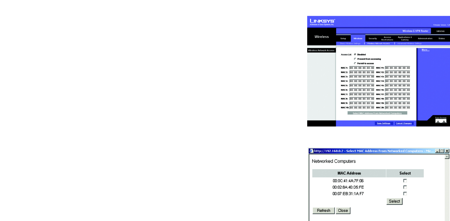
Wireless Network Access (See Figure 6-13.)
Wireless Network Access. If this function is enabled, only the computers on the list will be allowed access to the
wireless network. To add a computer to the network, click the Permit to access button, and enter the MAC
address in the fields. Click the Select MAC Address From Networked Computers button, and the screen in
Figure 6-15 will appear.
Select the MAC Address from the list and click the Select button.
To prevent access, click the Prevent from accessing button, then click Select MAC Address from the list.
From the screen in Figure 6-14, select the MAC Address from the list, and click the Select button.
Click the Refresh button if you want to refresh the screen. Click the Close button to return to th previous screen.
When finished making your changes on this tab, click the Save Settings button to save these changes, or click
the Cancel Changes button to undo your changes. Figure 6-13: Wireless Network Access
Figure 6-14: Networked Computers
30
Chapter 6: Configuring the Router
The Wireless Tab
Wireless-G VPN Broadband Router
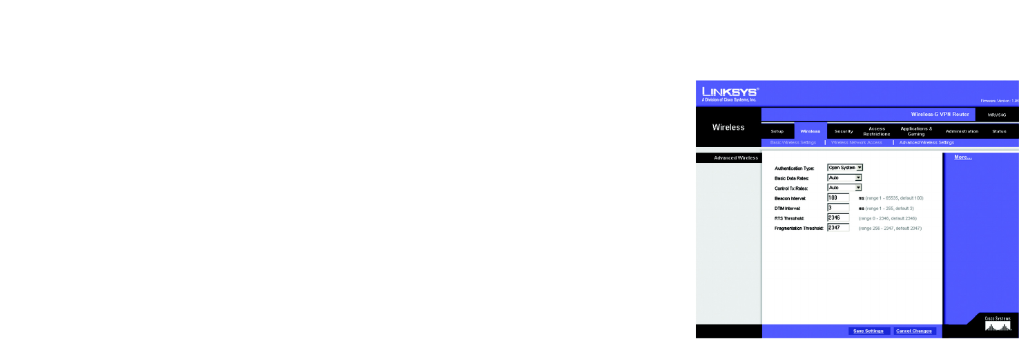
Advanced Wireless Settings (See Figure 6-15.)
On this screen you can access the Advanced Wireless features, including Authentication Type, Basic Data Rates,
Control Tx Rates, Beacon Interval, DTIM Interval, RTS Threshold, and Fragmentation Threshold.
• Authentication Type. The default is set to Auto, which allows either Open System or Shared Key
authentication to be used. For Open System authentication, the sender and the recipient do NOT use a WEP
key for authentication. For Shared Key authentication, the sender and recipient use a WEP key for
authentication. If you want to use only Shared Key authentication, then select Shared Key.
• Basic Data Rates. Select 1-2 Mbps, All, or Default, from the drop-down menu.
• Control Tx Rates. The default transmission rate is Auto. The range is from 1 to 54Mbps. The rate of data
transmission should be set depending on the speed of your wireless network. You can select from a range of
transmission speeds, or keep the default setting, Auto, to have the Router automatically use the fastest
possible data rate and enable the Auto-Fallback feature. Auto-Fallback will negotiate the best possible
connection speed between the Router and a wireless client.
• Beacon Interval. The default value is 100. Enter a value between 1 and 65,535 milliseconds. The Beacon
Interval value indicates the frequency interval of the beacon. A beacon is a packet broadcast by the Router to
synchronize the wireless network.
• DTIM Interval The default value is 3. This value, between 1 and 255 milliseconds, indicates the interval of the
Delivery Traffic Indication Message (DTIM). A DTIM field is a countdown field informing clients of the next
window for listening to broadcast and multicast messages. When the Router has buffered broadcast or
multicast messages for associated clients, it sends the next DTIM with a DTIM Interval value. Its clients hear
the beacons and awaken to receive the broadcast and multicast messages.
• RTS Threshold This value should remain at its default setting of 2347. The range is 0-2347 bytes. Should you
encounter inconsistent data flow, only minor modifications are recommended. If a network packet is smaller
than the preset RTS threshold size, the RTS/CTS mechanism will not be enabled. The Router sends Request to
Send (RTS) frames to a particular receiving station and negotiates the sending of a data frame. After receiving
an RTS, the wireless station responds with a Clear to Send (CTS) frame to acknowledge the right to begin
transmission.
• Fragmentation Threshold This value should remain at its default setting of 2346. The range is 256-2346
bytes. It specifies the maximum size for a packet before data is fragmented into multiple packets. If you
experience a high packet error rate, you may slightly increase the Fragmentation Threshold. Setting the
Fragmentation Threshold too low may result in poor network performance. Only minor modifications of this
value are recommended.
Figure 6-15: Advanced Wireless Settings
31
Chapter 6: Configuring the Router
The Security Tab
Wireless-G VPN Broadband Router
The Security Tab
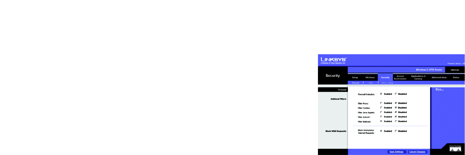
Firewall
When you click the Security tab, you will see the Firewall screen (see Figure 6-16). This screen contains Filters
and Block WAN Requests. Filters block specific internal users from accessing the Internet and block anonymous
Internet requests and/or multicasting.
• Firewall. To add Firewall Protection, click Enabled. If you do not want Firewall Protection, click Disabled.
• Filter Proxy. Use of WAN proxy servers may compromise the Router's security. Denying Filter Proxy will
disable access to any WAN proxy servers. To enable proxy filtering, click Enabled.
• Filter Cookies. A cookie is data stored on your PC and used by Internet sites when you interact with them. To
enable cookie filtering, click Enabled.
• Filter Java Applets. Java is a programming language for websites. If you deny Java Applets, you run the risk
of not having access to Internet sites created using this programming language. To enable Java Applet
filtering, click Enabled.
• Filter ActiveX. ActiveX is a programming language for websites. If you deny ActiveX, you run the risk of not
having access to Internet sites created using this programming language. To enable ActiveX filtering, click
Enabled.
• Filter Multicast. Multicasting allows for multiple transmissions to specific recipients at the same time. If
multicasting is permitted, then the Router will allow IP multicast packets to be forwarded to the appropriate
computers. Select Enabled to filter multicasting, or Disabled to disable this feature.
• Block Anonymous Internet Requests. This keeps your network from being “pinged” or detected and
reinforces your network security by hiding your network ports, so it is more difficult for intruders to work their
way into your network. Select Enabled to block anonymous Internet requests, or Disabled to allow
anonymous Internet requests.
When finished making your changes on this tab, click the Save Settings button to save these changes, or click
the Cancel Changes button to undo your changes.
Figure 6-16: Firewall