LINKSYS HGA5S-3 Wireless-G VPN Broadband Router User Manual Book
LINKSYS LLC Wireless-G VPN Broadband Router Book
LINKSYS >
Contents
- 1. Users Manual Part 1
- 2. Users Manual Part 2
- 3. Users Manual Part 3
- 4. Users Manual Part 4
- 5. User Manual Part 5
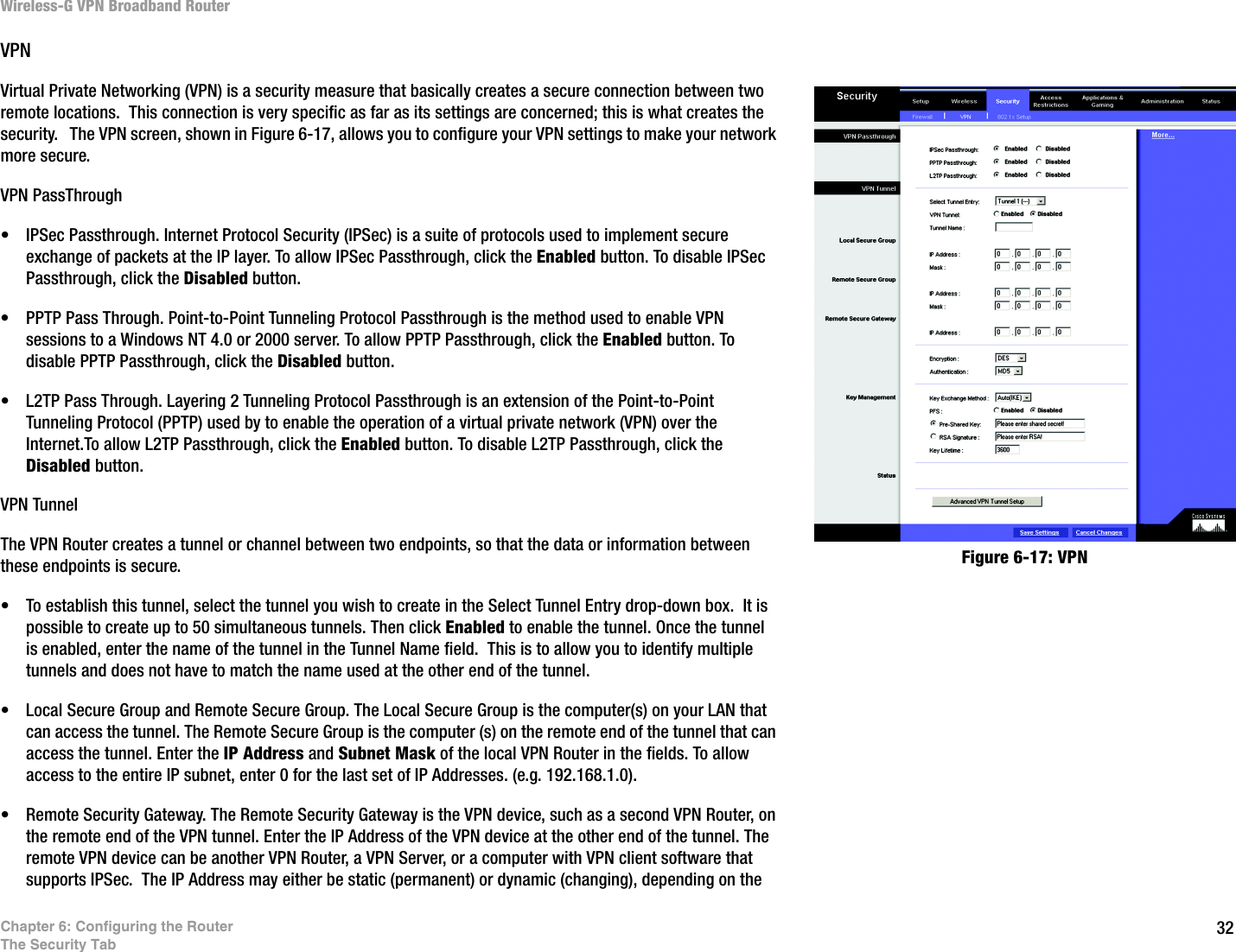
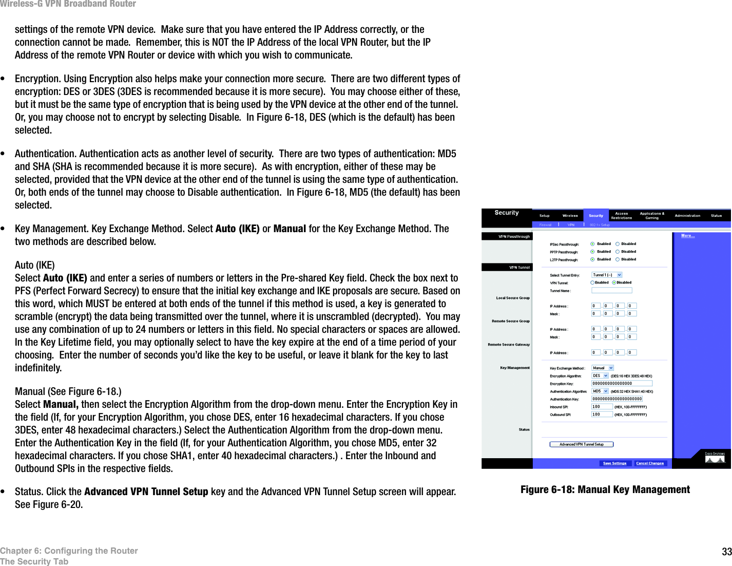
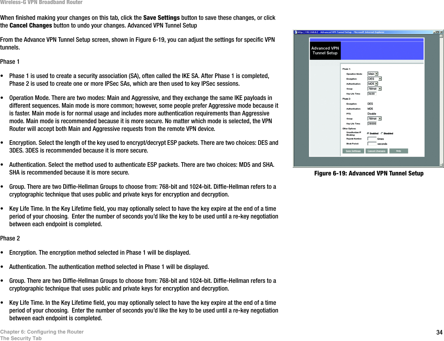
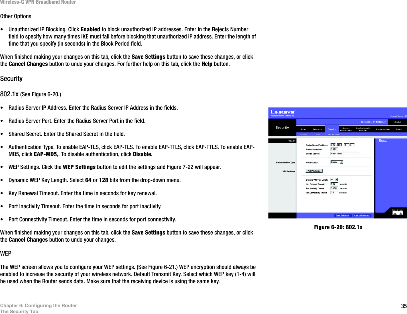
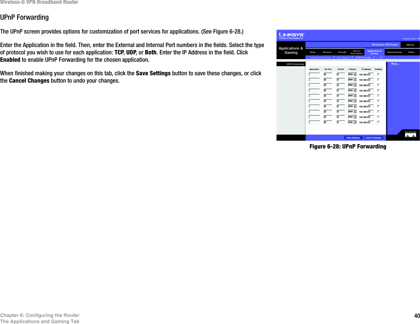
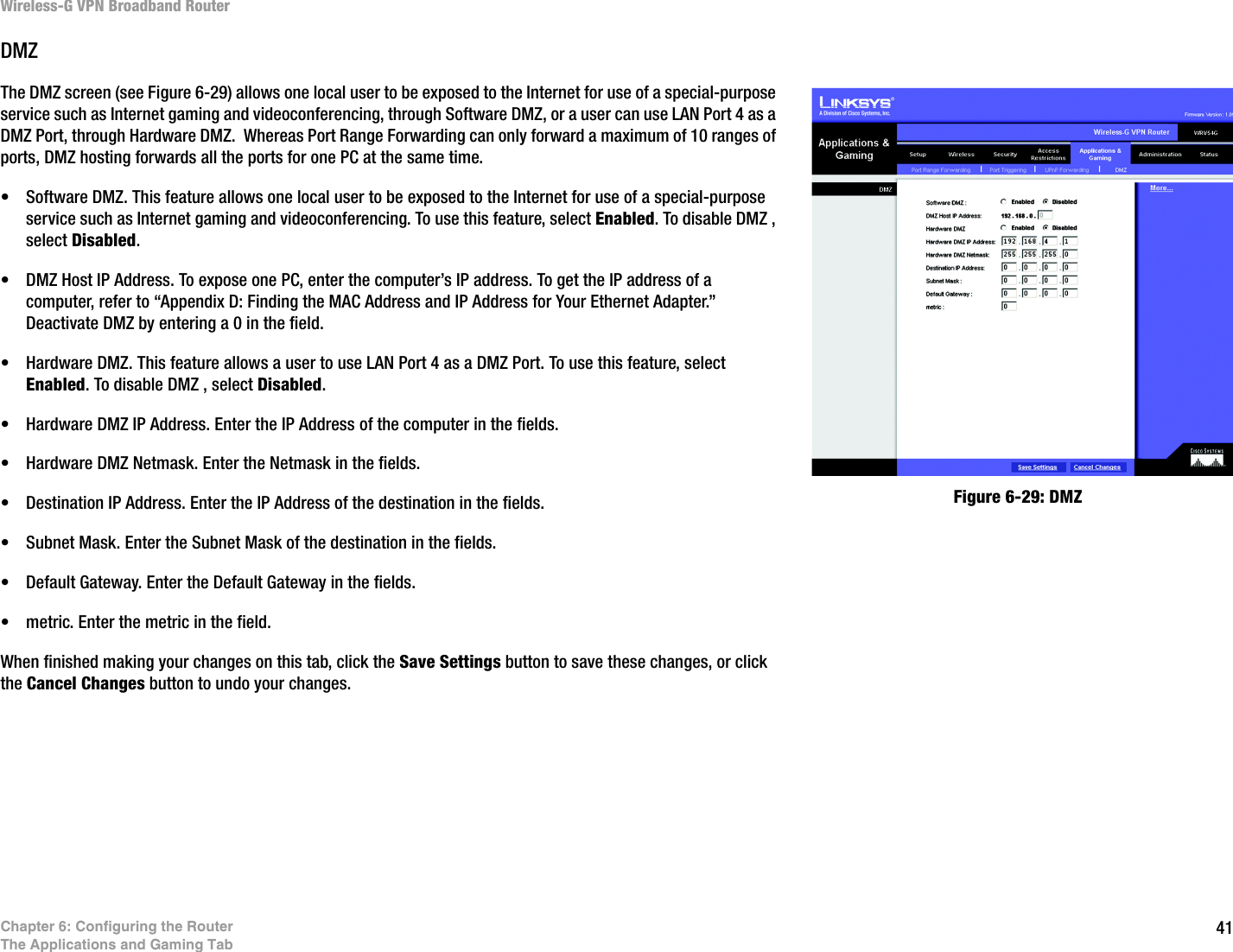
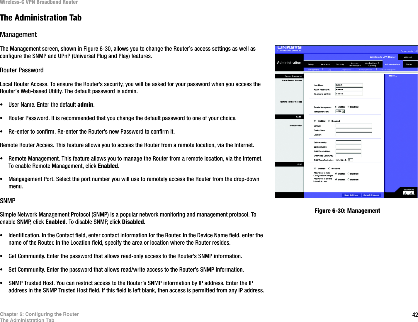
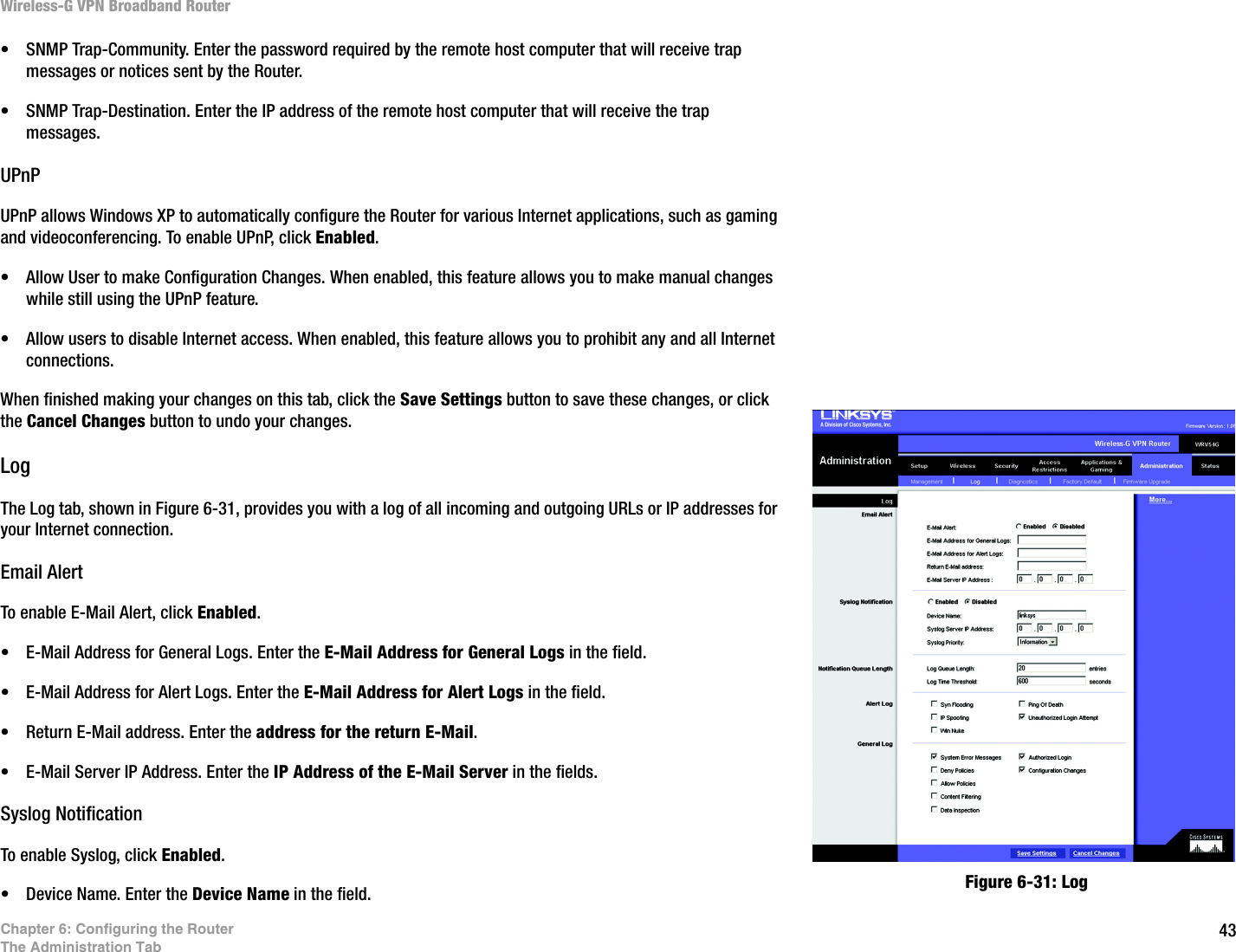
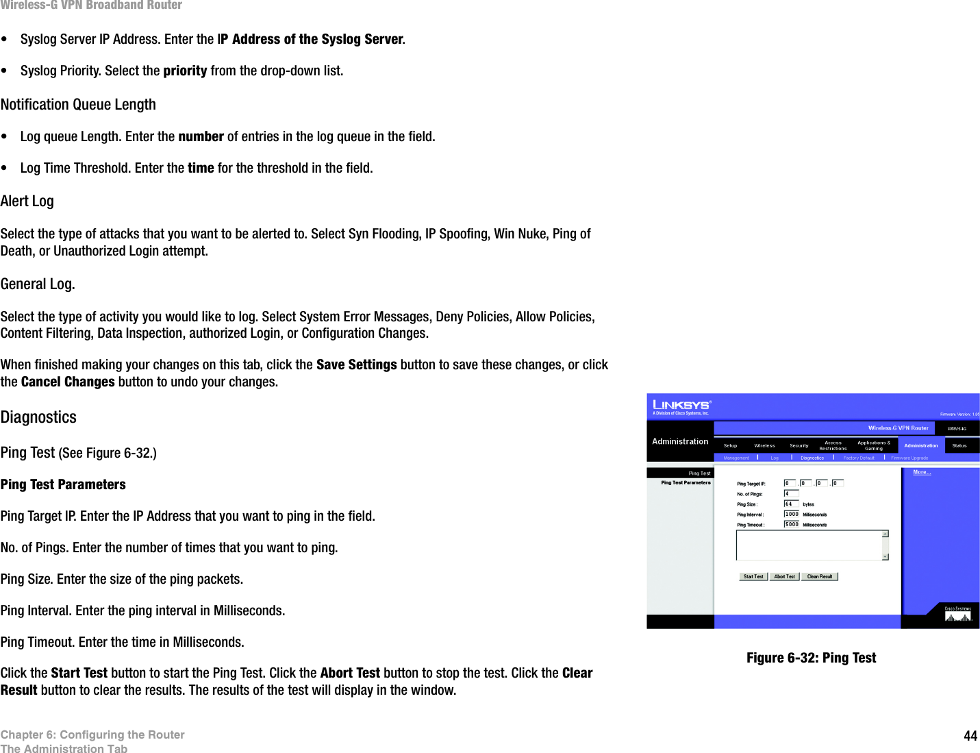
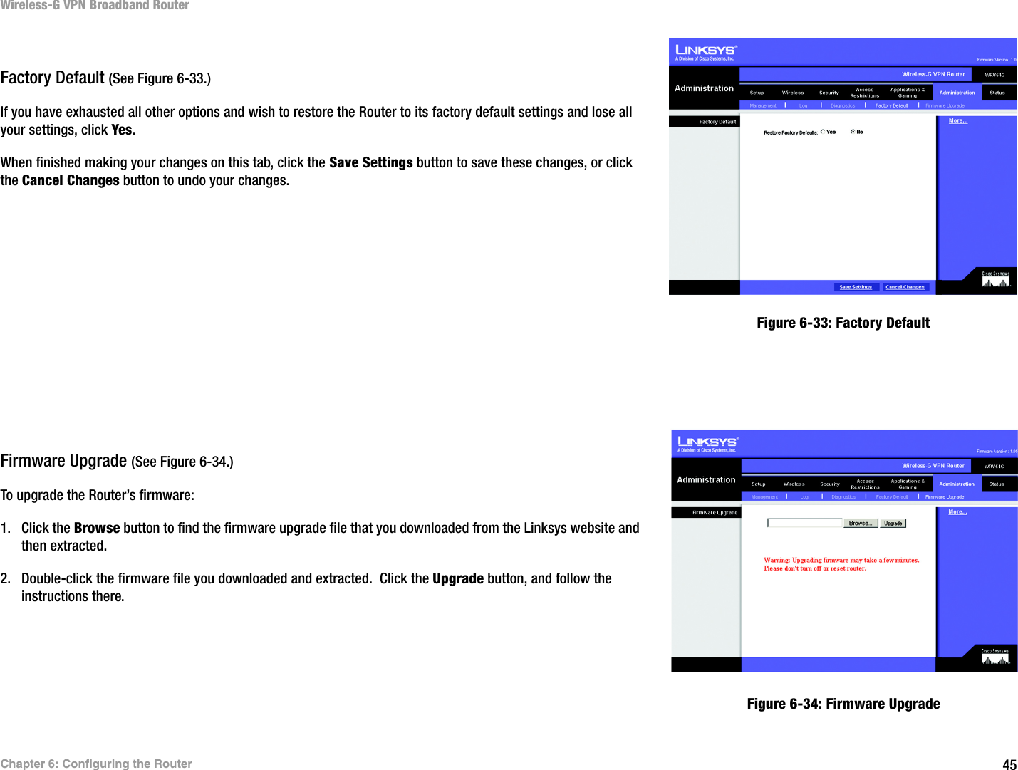
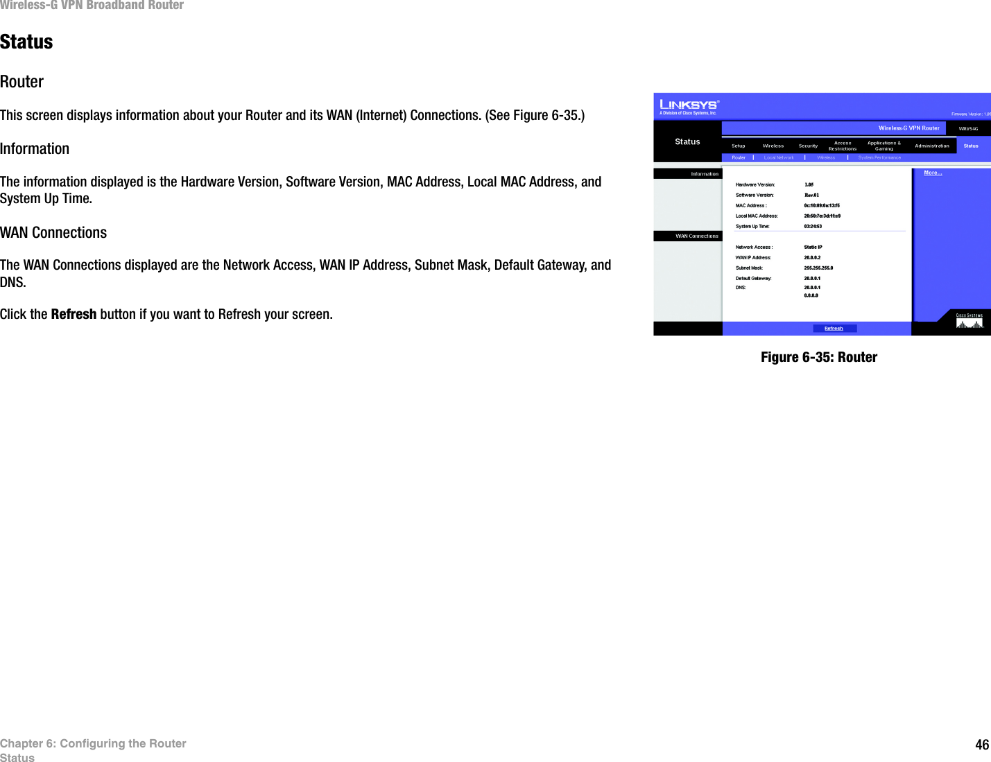
Users Manual Part 3