LINKSYS HGA5T-1 Wireless-G Broadband Router User Manual
LINKSYS LLC Wireless-G Broadband Router Users Manual
UserManual.wiki
>
LINKSYS
>
HGA5T 1 User Manual
Users Manual
Navigation menu
Upload a User Manual
Namespaces
Wiki Guide
HTML
PDF
Info
Views
User Manual
Discussion / Help
Navigation
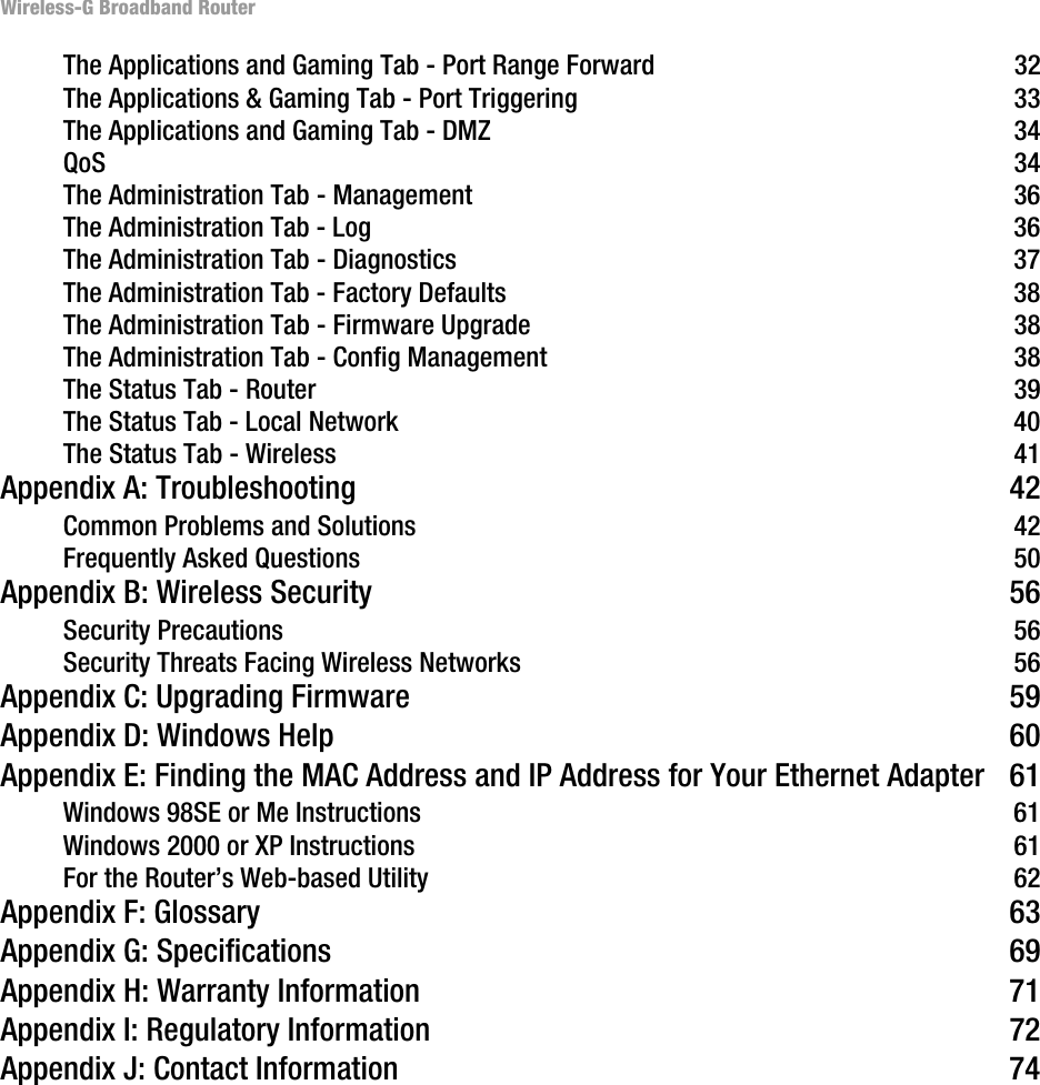
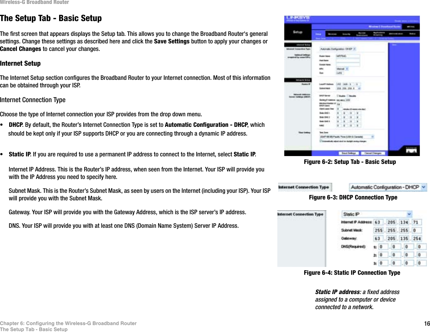
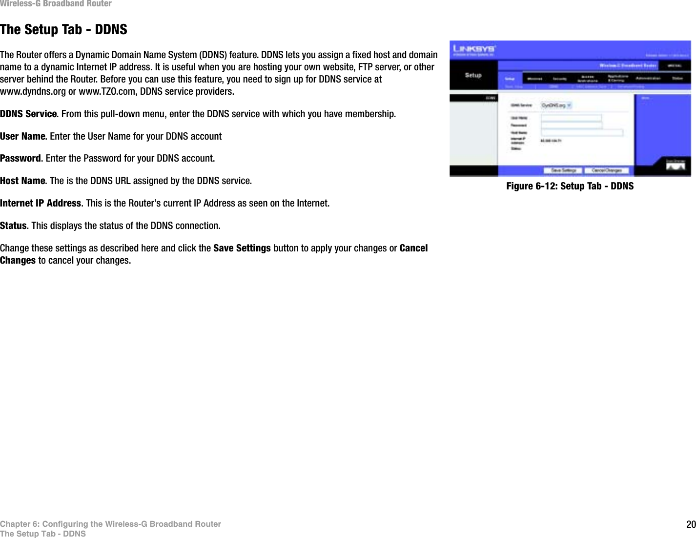
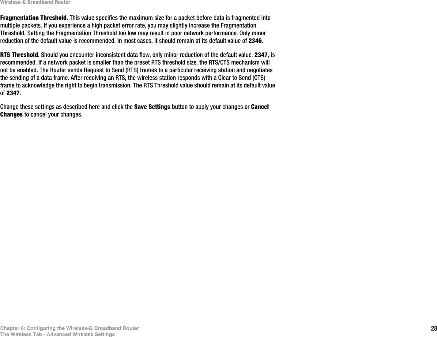
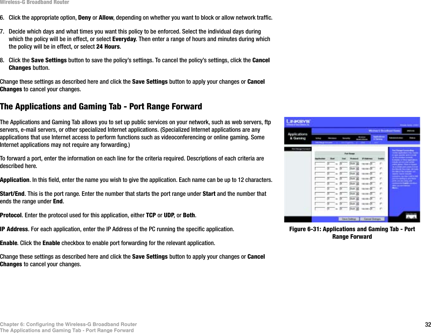
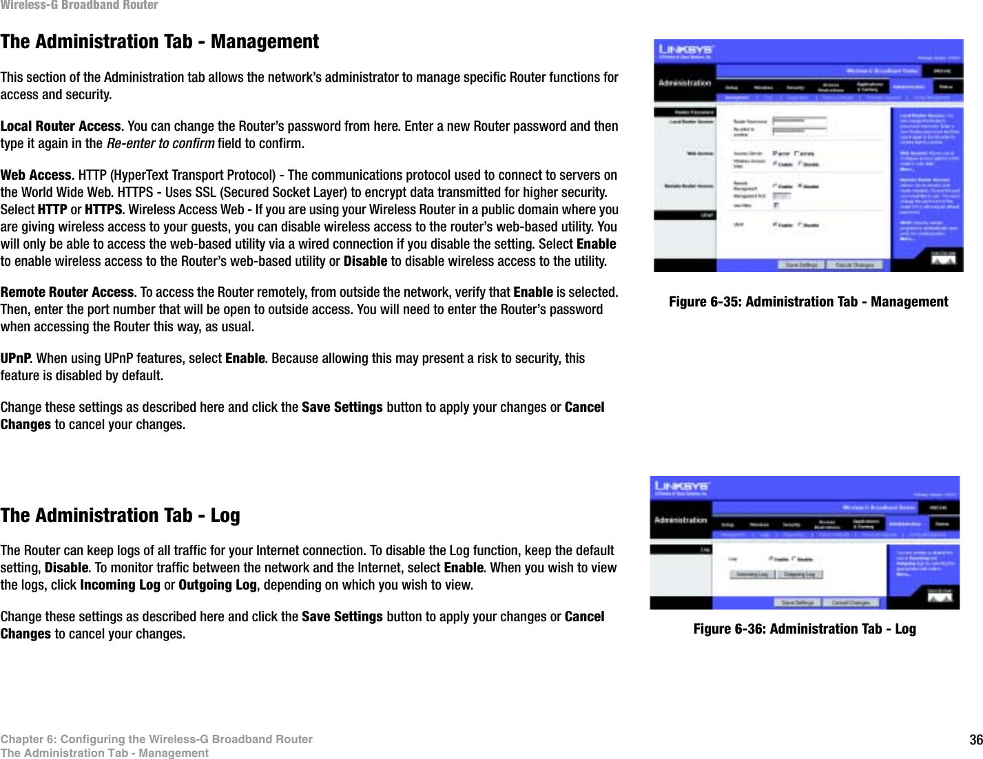
![51Appendix A: TroubleshootingFrequently Asked QuestionsWireless-G Broadband RouterI set up an Unreal Tournament Server, but others on the LAN cannot join. What do I need to do? If you have a dedicated Unreal Tournament server running, you need to create a static IP for each of the LAN computers and forward ports 7777, 7778, 7779, 7780, 7781, and 27900 to the IP address of the server. You can also use a port forwarding range of 7777 ~ 27900. If you want to use the UT Server Admin, forward another port. (Port 8080 usually works well but is used for remote admin. You may have to disable this.) Then in the [UWeb.WebServer] section of the server.ini file, set the ListenPort to 8080 (to match the mapped port above) and ServerName to the IP assigned to the Router from your ISP.Can multiple gamers on the LAN get on one game server and play simultaneously with just one public IP address? It depends on which network game or what kind of game server you are using. For example, Unreal Tournament supports multi-login with one public IP.How do I get Half-Life: Team Fortress to work with the Router? The default client port for Half-Life is 27005. The computers on your LAN need to have “+clientport 2700x” added to the HL shortcut command line; the x would be 6, 7, 8, and on up. This lets multiple computers connect to the same server. One problem: Version 1.0.1.6 won’t let multiple computers with the same CD key connect at the same time, even if on the same LAN (not a problem with 1.0.1.3). As far as hosting games, the HL server does not need to be in the DMZ. Just forward port 27015 to the local IP address of the server computer. How can I block corrupted FTP downloads? If you are experiencing corrupted files when you download a file with your FTP client, try using another FTP program.The web page hangs; downloads are corrupt, or nothing but junk characters are being displayed on the screen. What do I need to do? Force your Ethernet adapter to 10Mbps or half duplex mode, and turn off the “Auto-negotiate” feature of your Ethernet adapter as a temporary measure. (Please look at the Network Control Panel in your Ethernet adapter’s Advanced Properties tab.) Make sure that your proxy setting is disabled in the browser. Check our website at www.linksys.com for more information.If all else fails in the installation, what can I do? Reset the Router by holding down the reset button until the Power LED fully turns on and off. Reset your cable or DSL modem by powering the unit off and then on. Obtain and flash the latest firmware release that is readily available on the Linksys website, www.linksys.com.How will I be notified of new Router firmware upgrades? All Linksys firmware upgrades are posted on the Linksys website at www.linksys.com, where they can be downloaded for free. To upgrade the Router’s firmware, use the System tab of the Router’s web-based utility. If the Router’s Internet connection is working well, there is no need to download a newer firmware version, unless](https://usermanual.wiki/LINKSYS/HGA5T-1/User-Guide-477237-Page-58.png)
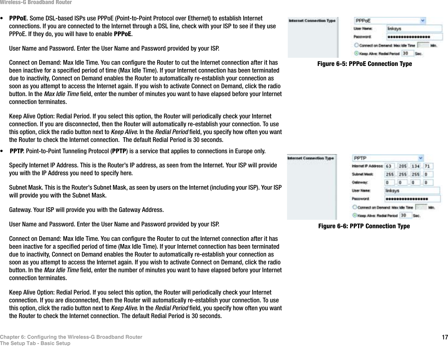
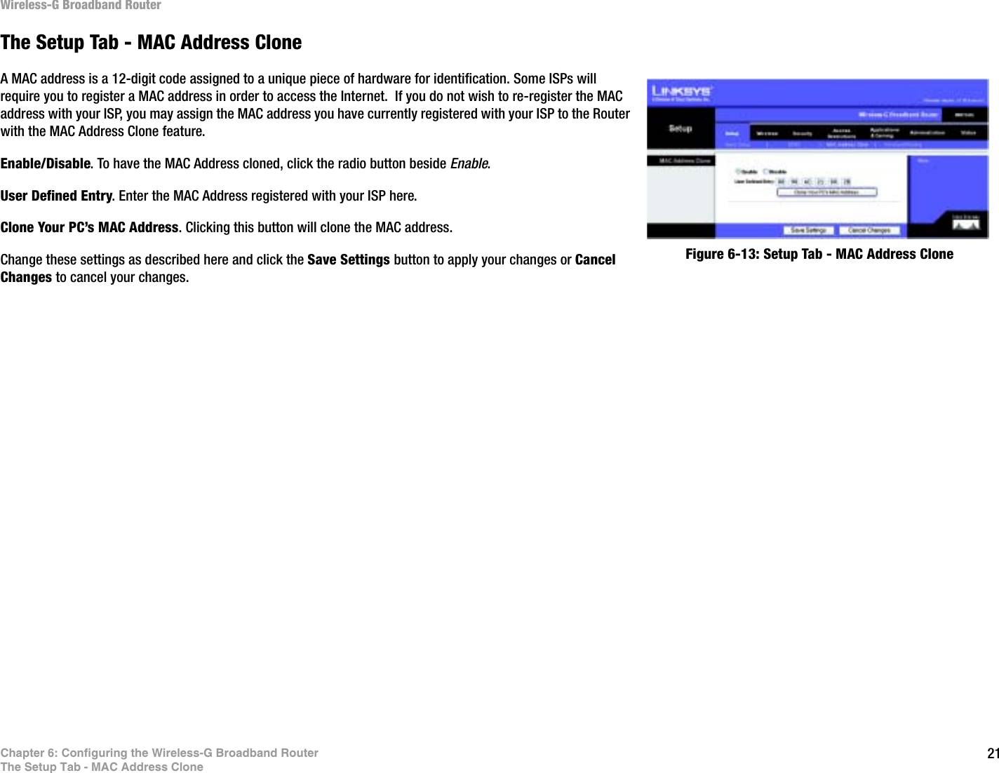
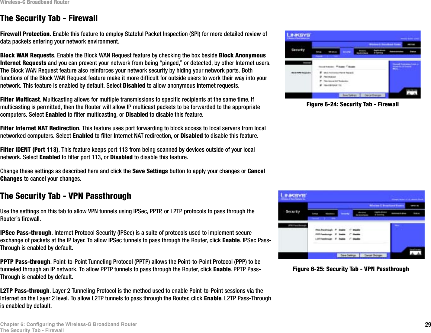
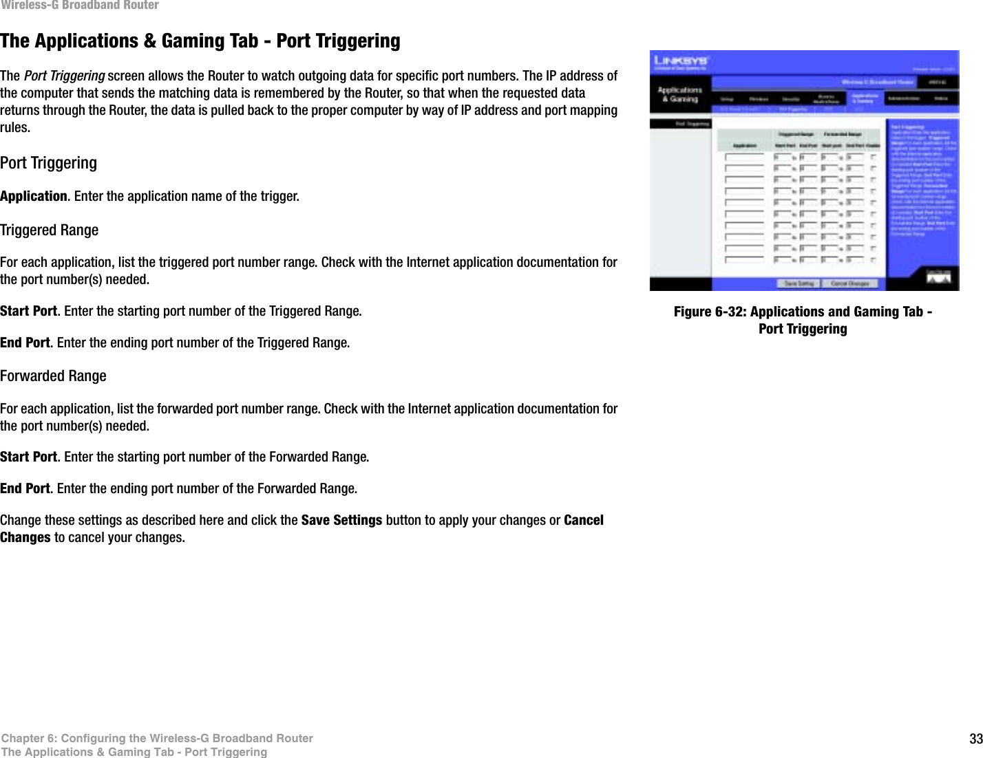
![72Appendix I: Regulatory InformationWireless-G Broadband RouterAppendix I: Regulatory InformationFCC STATEMENTThis product has been tested and complies with the specifications for a Class B digital device, pursuant to Part 15 of the FCC Rules. These limits are designed to provide reasonable protection against harmful interference in a residential installation. This equipment generates, uses, and can radiate radio frequency energy and, if not installed and used according to the instructions, may cause harmful interference to radio communications. However, there is no guarantee that interference will not occur in a particular installation. If this equipment does cause harmful interference to radio or television reception, which is found by turning the equipment off and on, the user is encouraged to try to correct the interference by one or more of the following measures:Reorient or relocate the receiving antennaIncrease the separation between the equipment or devicesConnect the equipment to an outlet other than the receiver'sConsult a dealer or an experienced radio/TV technician for assistanceFCC Radiation Exposure StatementThis equipment complies with FCC radiation exposure limits set forth for an uncontrolled environment. This equipment should be installed and operated with minimum distance 20cm between the radiator and your body.INDUSTRY CANADA (CANADA)This Class B digital apparatus complies with Canadian ICES-003.Cet appareil numérique de la classe B est conforme à la norme NMB-003 du Canada.The use of this device in a system operating either partially or completely outdoors may require the user to obtain a license for the system according to the Canadian regulations.EC DECLARATION OF CONFORMITY (EUROPE)Linksys declares that the Wireless-G Broadband Router conforms to the specifications listed below, following the provisions of the European R&TTE directive 1999/5/EC: EN 301 489-1, 301 489-17 General EMC requirements for Radio equipment.EN 609 50 SafetyEC DECLARATION OF CONFORMITY (EUROPE)Linksys declares that the Wireless-G Broadband Router conforms to the specifications listed below, following theprovisions of the European R&TTE directive 1999/5/EC:EN 301 489-1, 301 489-17 General EMC requirements for Radio equipment.EN 609 50 SafetyTo prevent radio interference to the licenced service, this device is intended to be operated indoors and away from windows to provide maximum shielding. Equipment (or its transmit antenna) that is installed outdoors is subject to licensing This equipment has been tested and found to comply with the limits for a Class B digital device, pursuant to Part 15 of the FCC Rules. These limits are designed to provide reasonable protection against harmful interference in a residential installation. This equipment generates, uses and can radiate radio frequency energy and, if not installed and used in accordance with the instructions, may cause harmful interference to radio communications. However, there is no guarantee that interference will not occur in a particular installation. If this equipment does cause harmful interference to radio or television reception, which can be determined by turning the equipment off and on, the user is encouraged to try to correct the interference by one of the following measures: - Reorient or relocate the receiving antenna. - Increase the separation between the equipment and receiver. - Connect the equipment into an outlet on a circuit different from that to which the receiver is connected. - Consult the dealer or an experienced radio/TV technician for help. This device complies with Part 15 of the FCC Rules. Operation is subject to the following two conditions: (1) This device may not cause harmful interference, and (2) this device must accept any interference received, including interference that may cause undesired operation. FCC Caution: Any changes or modifications not expressly approved by the party responsible for compliance could void the user's authority to operate this equipment. IMPORTANT NOTE: FCC Radiation Exposure Statement: This equipment complies with FCC radiation exposure limits set forth for an uncontrolled environment. This equipment should be installed and operated with minimum distance 20cm between the radiator & your body. This transmitter must not be co-located or operating in conjunction with any other antenna or transmitterLinksys declared that WRT54G v2.2 is limited in CH1~11 by specified firmware controlled in USA.INDUSTRY CANADA (CANADA)FCC STATEMENT"Operation is subject to the following two conditions: (1) this device may not cause interference, and (2) this device must accept any interference, including interference that may cause undesired operation of the device.""This device has been designed to operate with an antenna having a maximum gain of [x] dB. Antenna having a higher gain is strictly prohibited per regulations of Industry Canada. The required antenna impedance is [ y] ohms." "To reduce potential radio interference to other users, the antenna type and its gain should be so chosen that the equivalent isotropically radiated power (EIRP) is not more than that required for successful communication"."To prevent radio interference to the licensed service, this device is intended to be operated indoors and away from windows to provide maximum shielding. Equipment (or its transmit antenna) that is installed outdoors is subject to licensing."](https://usermanual.wiki/LINKSYS/HGA5T-1/User-Guide-477237-Page-80.png)