LINKSYS HGA5T-4 Wireless Network Access Point User Manual WAP11 V2 8 UG Rev NC
LINKSYS LLC Wireless Network Access Point WAP11 V2 8 UG Rev NC
LINKSYS >
Manual
Wireless-B Access
Point
Use this guide to install: WAP11 User Guide

COPYRIGHT & TRADEMARKS
Specifications are subject to change without notice. Linksys is a registered trademark or
trademark of Cisco Systems, Inc. and/or its affiliates in the U.S. and certain other countries.
Copyright © 2003 Cisco Systems, Inc. All rights reserved. Other brands and product
names are trademarks or registered trademarks of their respective holders.
LIMITED WARRANTY
Linksys warrants to the original end user purchaser (“You”) that, for a period of one year,
(the “Warranty Period”) Your Linksys product will be free of defects in materials and work-
manship under normal use. Your exclusive remedy and Linksys’s entire liability under this
warranty will be for Linksys at its option to repair or replace the product or refund Your pur-
chase price less any rebates.
If the product proves defective during the Warranty Period call Linksys Technical Support
in order to obtain a Return Authorization Number. BE SURE TO HAVE YOUR PROOF OF
PURCHASE ON HAND WHEN CALLING. When returning a product, mark the Return
Authorization Number clearly on the outside of the package and include a copy of your
original proof of purchase. RETURN REQUESTS CANNOT BE PROCESSED WITHOUT
PROOF OF PURCHASE. You are responsible for shipping defective products to Linksys.
Linksys pays for UPS Ground shipping from Linksys back to You only. Customers located
outside of the United States of America and Canada are responsible for all shipping and
handling charges.
ALL IMPLIED WARRANTIES AND CONDITIONS OF MERCHANTABILITY OR FITNESS FOR
A PARTICULAR PURPOSE ARE LIMITED TO THE DURATION OF THE WARRANTY PERI-
OD. ALL OTHER EXPRESS OR IMPLIED CONDITIONS, REPRESENTATIONS AND WAR-
RANTIES, INCLUDING ANY IMPLIED WARRANTY OF NON-INFRINGEMENT, ARE DIS-
CLAIMED. Some jurisdictions do not allow limitations on how long an implied warranty lasts,
so the above limitation may not apply to You. This warranty gives You specific legal rights,
and You may also have other rights which vary by jurisdiction.
TO THE EXTENT NOT PROHIBITED BY LAW, IN NO EVENT WILL LINKSYS BE LIABLE
FOR ANY LOST DATA, REVENUE OR PROFIT, OR FOR SPECIAL, INDIRECT, CONSE-
QUENTIAL, INCIDENTAL OR PUNITIVE DAMAGES, HOWEVER CAUSED REGARDLESS
OF THE THEORY OF LIABILITY, ARISING OUT OF OR RELATED TO THE USE OF OR
INABILITY TO USE THE PRODUCT, EVEN IF LINKSYS HAS BEEN ADVISED OF THE POS-
SIBILITY OF SUCH DAMAGES. IN NO EVENT WILL LINKSYS' LIABILITY EXCEED THE
AMOUNT PAID BY YOU FOR THE PRODUCT.
The foregoing limitations will apply even if any warranty or remedy provided under this
Section fails of its essential purpose. Some jurisdictions do not allow the exclusion or limi-
tation of incidental or consequential damages, so the above limitation or exclusion may not
apply to You.
Please direct all inquiries to: Linksys, P.O. Box 18558, Irvine, CA 92623.
FCC STATEMENT
This product has been tested and complies with the specifications for a Class B digital
device, pursuant to Part 15 of the FCC Rules. These limits are designed to provide rea-
sonable protection against harmful interference in a residential installation. This equip-
ment generates, uses, and can radiate radio frequency energy and, if not installed and
used according to the instructions, may cause harmful interference to radio communi-
cations. However, there is no guarantee that interference will not occur in a particular
installation. If this equipment does cause harmful interference to radio or television
reception, which is found by turning the equipment off and on, the user is encouraged to
try to correct the interference by one or more of the following measures:
• Reorient or relocate the receiving antenna
• Increase the separation between the equipment or devices
• Connect the equipment to an outlet other than the receiver’s
• Consult a dealer or an experienced radio/TV technician for assistance
FCC Radiation Exposure Statement
This equipment complies with FCC radiation exposure limits set forth for an uncontrolled
environment. This equipment should be installed and operated with minimum distance
20cm between the radiator and your body.
INDUSTRY CANADA (CANADA)
This Class B digital apparatus complies with Canadian ICES-003.
Cet appareil numérique de la classe B est conforme à la norme NMB-003 du Canada.
The use of this device in a system operating either partially or completely outdoors may
require the user to obtain a license for the system according to the Canadian regulations.
EC DECLARATION OF CONFORMITY (EUROPE)
Linksys Group declares that the Wireless-B Access Point conforms to the specifications
listed below, following the provisions of the European R&TTE directive 1999/5/EC:
For 11Mbps, 2.4 GHz devices with 100 mW radios, the following standards were applied:
• EN 301 489-1, 301 489-17 General EMC requirements for Radio equipment.
• EN 609 50 Safety
• ETS 300-328-2 Technical requirements for Radio equipment.
Caution: This equipment is intended to be used in all EU and EFTA countries. Outdoor
use may be restricted to certain frequencies and/or may require a license for operation.
Contact local Authority for procedure to follow.
Note: Combinations of power levels and antennas resulting in a radiated power level of
above 100 mW equivalent isotropic radiated power (EIRP) are considered as not com-
pliant with the above mentioned directive and are not allowed for use within the European
community and countries that have adopted the European R&TTE directive 1999/5/EC.
For more details on legal combinations of power levels and antennas, contact Linksys
Corporate Compliance.
• Linksys Group vakuuttaa täten että Wireless-B Access Point tyyppinen laite on direk-
tiivin 1999/5/EY oleellisten vaatimusten ja sitä koskevien näiden direktiivien muiden
ehtojen mukainen.
• Linksys Group déclare que la Wireless-B Access Point est conforme aux conditions
essentielles et aux dispositions relatives à la directive 1999/5/EC.
This device complies with Part 15 of the FCC Rules. Operation is subject to the following
two conditions: (1) This device may not cause harmful interference, and (2) this device
must accept any interference received, including interference that may cause undesired
operation.
This transmitter must not be co-located or operating in conjunction with any other antenna or transmitter.

Table of Contents
Chapter 1: Introduction 1
The Wireless-B Access Point 1
Features 1
Chapter 2: Planning Your Wireless Network 2
Network Topology 2
Ad-Hoc versus Infrastructure Mode 2
Chapter 3: Getting to Know the Wireless-B
Access Point 4
The Wireless-B Access Point’s Ports 4
The Wireless-B Access Point’s LEDs 5
Chapter 4: Connecting the Wireless-B
Access Point 6
Chapter 5: Setting Up the Wireless-B
Access Point 7
Chapter 6: Configuring the Wireless-B
Access Point 15
The Setup Tab 15
The Password Tab 22
The Status Tab 23
The Log Tab 25
The Help Tab 26
The Filter Tab 27
The Wireless Tab 29
Appendix A: Troubleshooting 32
Common Problems and Solutions 32
Frequently Asked Questions 32
Appendix B: Setting Up the TCP/IP Protocol 36
Setting Up TCP/IP in Windows 36
TCP/IP Setup for Windows 98 and Millennium 37
TCP/IP Setup for Windows 2000 38
TCP/IP Setup for Windows XP 39
• Dans le cas d'une utilisation privée, à l'extérieur d'un bâtiment, au-dessus d'un
espace public, aucun enregistrement n'est nécessaire pour une distance de moins
de 300m. Pour une distance supérieure à 300m un enregistrement auprès de l'IBPT
est requise. Pour une utilisation publique à l'extérieur de bâtiments, une licence de
l'IBPT est requise. Pour les enregistrements et licences, veuillez contacter l'IBPT.
• France F:
2.4 GHz Bande : les canaux 10, 11, 12, 13 (2457, 2462, 2467, et 2472 MHz respec-
tivement) sont complétement libres d'utilisation en France (en utilisation intérieur).
Pour ce qui est des autres canaux, ils peuvent être soumis à autorisation selon le
départment. L'utilisation en extérieur est soumis à autorisation préalable et très
restreint.
Vous pouvez contacter l'Autorité de Régulation des Télécommunications
(http://www.art-telecom.fr) pour de plus amples renseignements.
2.4 GHz Band: only channels 10, 11, 12, 13 (2457, 2462, 2467, and 2472 MHz
respectively) may be used freely in France for indoor use. License required for out-
door installations.
Please contact ART (http://www.art-telecom.fr) for procedure to follow.
WAP11_V2.8-UG-30730NC JL
Cisco-Linksys, LLC declares that WAP11V28 ( FCC ID: Q87-HGA5T-4) is
limited in CH1~CH11 by specified firmware controlled in U.S.A.

6
Chapter 1: Introduction
Set your network free! The Wireless Access Point from Linksys connects wire-
less computers to your wired network, so you can add PCs to the network with
no cabling hassle. Create a “wireless bubble” in that hard-to-wire office space,
and save the time, hassle, and expense of running cables. Plus, notebook PCs
can travel around your home or office and stay connected wherever they go.
You can also use the Wireless Access Point as a kind of “cable-less cable” to
connect remote areas together. Maybe Shipping is all the way across the ware-
house from Receiving. Or maybe you want to set up a home office in your
detached garage. With a Wireless Access Point in the garage, and another one
(or the Linksys Wireless Ethernet Bridge) in the house, you’re connected—
with no cable to run.
For even more versatility, the Wireless Access Point can act as a Repeater. If
you’re already using one WAP11, you can extend your wireless network’s range
by installing a second one that “bounces” received data further down the line.
The repeating Access Point can be installed nearly anywhere, because it works
entirely by radio—no data cable is necessary.
Whichever mode you use, the dual antenna configuration provides “antenna
diversity”, for exceptional signal sensitivity and increased usable range. To pro-
tect your data and privacy the Wireless Access Point can encrypt all wireless
transmissions. The MAC Address filter lets you decide exactly who has access
to your wireless network. Configuration is a snap with web browser-based con-
figuration.
The Linksys Wireless Access Point is the simple, versatile way to add wireless
capabilities to your network.
• High-Speed Data Transfer Rates of up to 11Mbps
• Compatible with IEEE 802.11b, 2.4GHz Compliant Equipment
• Supports Wireless Bridging, Wireless Repeater, MAC Address Filtering,
and Event Logging
• Setup Wizard for Easy Installation
• Built-in Web-based Utility for Easy Configuration from any Web Browser
• Wireless Security with Up to 128-bit WEP Encryption
1
Appendix C: Glossary 40
Appendix D: Specifications 48
Environmental 48
Appendix E: Warranty Information 49
Appendix F: Contact Information 50
Features
The Wireless-B Access Point
3
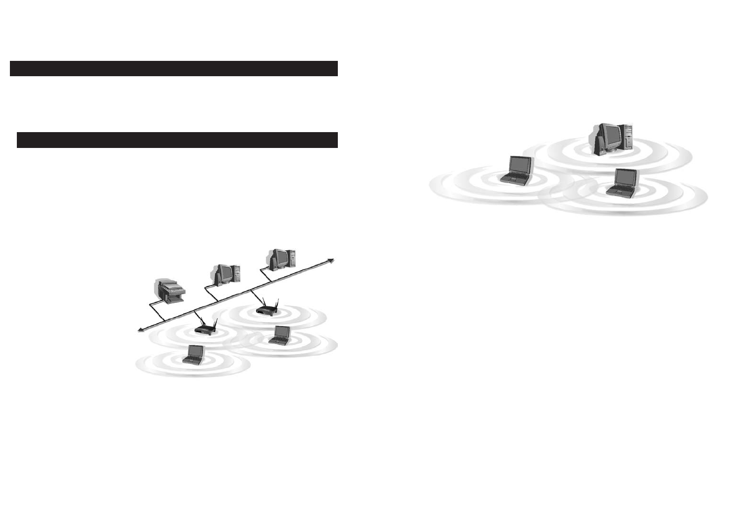
If the wireless network is relatively small and needs to share resources only
with the other computers on the wireless network, then the ad-hoc mode can
be used. (See Figure 2-2.) Ad-hoc mode allows computers equipped with wire-
less transmitters and receivers to communicate directly with each other, elimi-
nating the need for an access point. The drawback of this mode is that, in Ad-
Hoc mode, wireless-equipped computers are not able to communicate with
computers on a wired network. And, of course, communication between the
wireless-equipped computers is limited by the distance and interference direct-
ly between them.
Chapter 2: Planning Your
Wireless Network
A wireless local area network (WLAN) is exactly like a regular local area net-
work (LAN), except that each computer in the WLAN uses a wireless device to
connect to the network. Computers in a WLAN share the same frequency
channel and SSID, which is an identification name for wireless devices.
Unlike wired networks, wireless networks have two different modes in which
they may be set up: infrastructure and ad-hoc. An infrastructure configura-
tion is a WLAN and wired LAN communicating to each other through an
access point. An ad-hoc configuration is wireless-equipped computers com-
municating directly with each other. Choosing between these two modes
depends on whether or not the wireless network needs to share data or periph-
erals with a wired network or not.
If the computers on the
wireless network need to
be accessed by a wired
network or need to share a
peripheral, such as a print-
er, with the wired network
computers, the wireless
network should be set up
in infrastructure mode.
(See Figure 2-1.) The
basis of infrastructure
mode centers around an
access point, which serves
as the main point of com-
munications in a wireless network. Access points transmit data to PCs equipped
with wireless network cards, which can roam within a certain radial range of
the access point. Multiple access points can be arranged to work in succession
to extend the roaming range, and can be set up to communicate with your
Ethernet (wired) hardware as well.
2
Network Topology
Ad-Hoc versus Infrastructure Mode
Figure 2-1
Figure 2-2
5
Chapter 3: Getting to Know the
Wireless-B Access Point
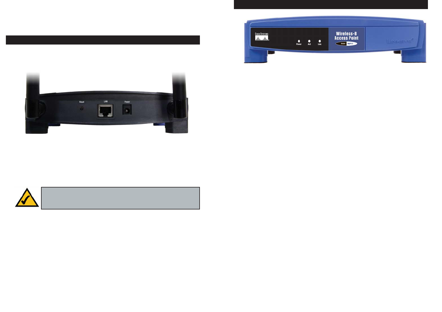
The Access Point’s ports and Reset button are located on the Access Point’s rear
panel.
Reset Button There are two ways to reset the Access Point’s factory
defaults. Briefly press the Reset Button for approximately
ten seconds, or use the Password tab of the Access Point’s
Web-based Utility.
LAN This LAN (Local Area Network) port connects to
Ethernet network devices, such as a hub, switch, or
router.
Power The Power port is where you will connect the power
adapter.
4
T
Power Red. The Power LED lights up when the Access Point is
powered on.
Act Green. If the Act LED is flickering, the Access Point is
actively sending or receiving data to or from one of the
devices on the wireless network.
Link Orange. The Link LED serves two purposes. If the LED is
continuously lit up, the Access Point is successfully connect-
ed to a device through the LAN port. If the LED is flicker-
ing, it is an indication of any wired network activity.
The Wireless-B Access Point’s LEDs
Figure 3-2
The Wireless-B Access Point’s Ports
Figure 3-1
Important: Resetting the Access Point will erase all of your settings
(WEP Encryption, Wireless, and LAN settings, etc.) and replace
them with the factory defaults.
Chapter 5: Setting Up the
Wireless-B Access Point
Now that you’ve connected the Access Point to your wired network, you are
ready to begin setting it up. The Setup Wizard will take you through all the
steps necessary to configure the Access Point, so your wireless and wired net-
works will be able to communicate and share resources.
1. Insert the Setup Wizard CD into your PC’s CD-ROM drive. Optimally, your
PC should be on your wired network.
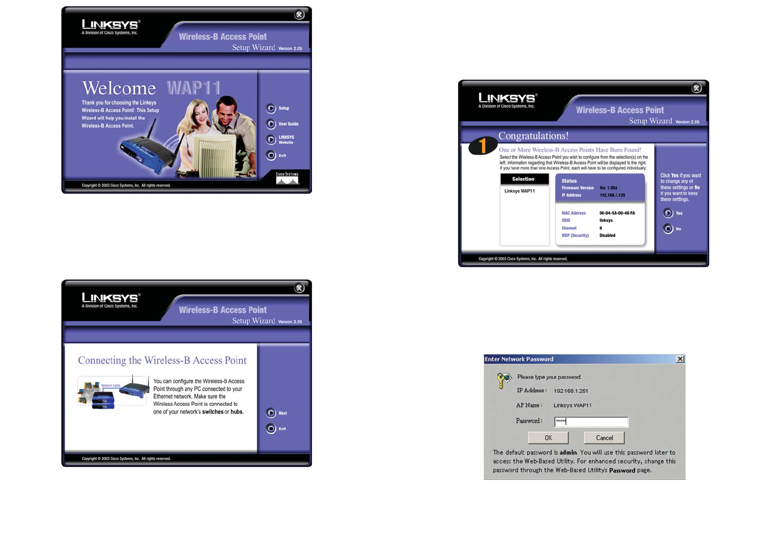
2. The screen in Figure 5-1 should appear on your monitor. If it does not, this
means the autorun is not functioning. Start the autorun manually by click-
ing the Start button, selecting Run, and typing D:\setup.exe (if “D” is your
PC’s CD-ROM drive). Click the Setup button to run the Setup Wizard.
Clicking the User Guide button opened this User Guide. To access the
Linksys website on an active Internet connection, click the LINKSYS
WEB button, or to exit this Setup Wizard, click the Exit button.
7
Chapter 4: Connecting the
Wireless-B Access Point
1. Locate an optimum location for the Access Point. The best place for the
Access Point is usually at the center of your wireless network, with line of
sight to all of your wireless devices.
2. Fix the direction of the antennas. Try to place it in a position which can best
cover your wireless network. Normally, the higher you place the antennas,
the better the performance will be. Their positioning enhances the receiving
sensitivity. Both antennas should be perpendicular to the ground and paral-
lel to each other.
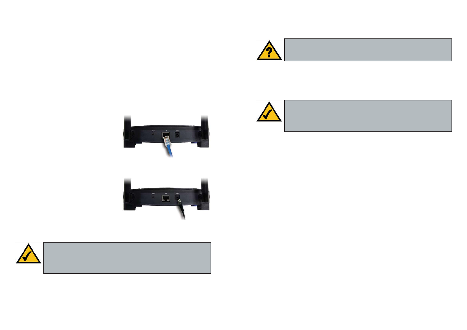
3. Connect the included Category 5
Ethernet network cable to the Access
Point. Then, connect the other end of
the Ethernet cable to a switch or hub.
The Access Point will then be con-
nected to your wired network.
4. Connect the AC power adapter to the
Access Point’s Power port. Only use
the power adapter supplied with the
Access Point. Use of a different
adapter may result in product damage.
Proceed to “Chapter 5: Setting Up the Wireless-B Access Point” for direc-
tions on how to set up the Access Point.
6
Have You: Connected the Access Point to a hub, switch, or router
on your wired network as shown in “Chapter 4: Connecting the
Wireless-B Access Point”?
Note: While the Access Point has been designed to work correctly
right out of the box, setting it up on a wireless computer will
require you to use the Linksys default settings. These settings can
then be changed through the Web-based Utility.
Note: In order for all other wireless devices to communicate with
the Access Point, those devices must be operating in the infrastruc-
ture mode. If any wireless devices are configured in the ad-hoc
mode, they will not be recognized by the Access Point.
Figure 4-1
Figure 4-2
9
4. The next screen to appear, shown in Figure 5-3, will display a list of access
points on your network, along with the status information for each access
point. If there is only one access point on your network, it will be the only
one displayed. If there are more than one displayed, select the Access Point
by clicking on it, and click the Ye s button to continue or No to exit the Setup
Wizard.
5. On the Enter Network Password screen, enter the default password, admin,
in the Password field. Then click the OK button. For added security,
remember to change this password later through the Web-based Utility’s
Password screen.
Figure 5-3
3. You can configure the Access Point through any PC connected to your
wired network. Make sure the Access Point is connected to one of your net-
work switches or hubs. Click the Next button to continue or Exit to exit the
Setup Wizard.
8
Figure 5-2
Figure 5-1
Figure 5-4
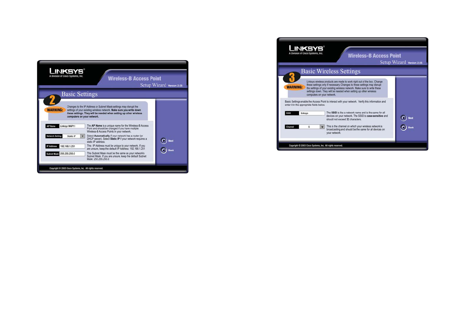
7. As shown in Figure 5-6, the Basic Wireless Settings screen will now appear.
Enter your wireless network’s SSID, and select the channel at which the net-
work broadcasts its wireless signal. Then, click the Next button to continue
or Back to return to the previous page.
• SSID. The SSID is the unique name shared among all devices in a wire-
less network. The SSID must be identical for all devices in the wireless
network. It is case-sensitive and must not exceed 32 characters, which
may be any keyboard character.
• Channel. Select the appropriate channel from the list provided to corre-
spond with your network settings. All devices in your wireless network
must use the same channel in order to function correctly.
11
6. As shown in Figure 5-5, the Basic Settings screen will appear next. Enter a
unique name in the AP Name field. From the Network Setting drop-down
menu, select Automatically if your network has a router or other DHCP
server, or select Static IP if your network does not have a DHCP server. If
you selected Static IP, then enter an IP Address and Subnet Mask appropri-
ate for your network. Click the Next button to continue or Back to return
to the previous page.
• AP Name. You may assign any name to the Access Point. Unique, mem-
orable names are helpful, especially if you are using multiple access
points on the same wireless network.
• Network Setting. Select Automatically if the Access Point will be
assigned an IP address by your network router. Select Static IP if you
will assign the Access Point a fixed IP address.
• IP Address. This IP address must be unique to your network. (The
default IP address is 192.168.1.251.) As this is a private IP address, there
is no need to purchase a separate IP address from your service provider.
• Subnet Mask. The Access Point’s Subnet Mask must be the same as your
wired network.
10
Figure 5-6
Figure 5-5
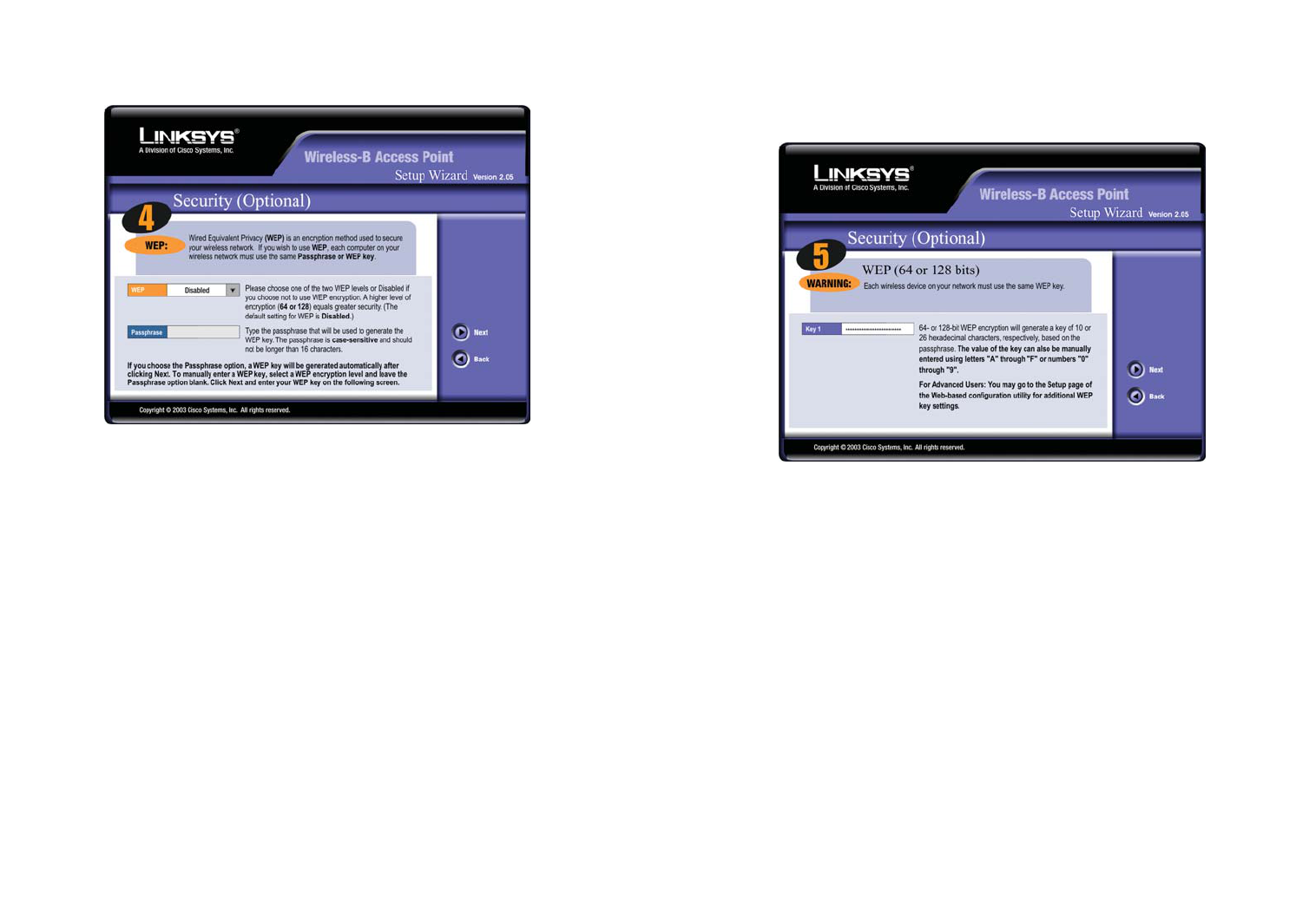
9. The second Security screen, shown in Figure 5-8, shows the WEP key. If
you entered a passphrase, then the Key 1 field will display the automatical-
ly generated WEP key. If you did not enter a passphrase, then enter a WEP
key in the Key 1 field. Each device in your wireless network must use the
same WEP key for the network to function properly. Click the Next button
to continue or Back to return to the previous page.
• Key 1. WEP keys enable you to create an encryption scheme for wire-
less LAN transmissions. If the WEP key hasn’t been automatically gen-
erated, then manually enter a set of values. (Do not leave the field blank,
and do not enter all zeroes. These are not valid key values.) If you are
using 64-bit WEP encryption, then each key must consist of exactly 10
hexadecimal characters. If you are using 128-bit WEP encryption, then
each key must consist of exactly 26 hexadecimal characters. Valid hexa-
decimal characters are “0”-“9” and “A”-“F”.
13
8. The Security screen (Figure 5-7) will appear next. From this screen, you
will set the Wired Equivalent Privacy (WEP) encryption for your wireless
network. Select a level of WEP encryption and enter a passphrase. Click the
Next button to continue or Back to return to the previous page.
• WEP. In order to utilize WEP encryption, select the WEP setting from
the pull-down menu, 64-bit (10 hex digits) or 128-bit (26 hex digits). If
you do not wish to utilize WEP encryption, make sure Disabled is select-
ed. The Access Point’s WEP encryption is unique to Linksys and may
conflict with other vendors’ WEP encryption.
• Passphrase. Instead of manually entering WEP keys, you can enter a
Passphrase. This Passphrase is used to generate one or more WEP keys.
It is case-sensitive and should not be longer than 16 alphanumeric char-
acters. (The Passphrase function is compatible with Linksys wireless
products only. If you want to communicate with non-Linksys wireless
products, you will need to enter your WEP keys manually on the non-
Linksys wireless products.)
12
Figure 5-8
Figure 5-7
15
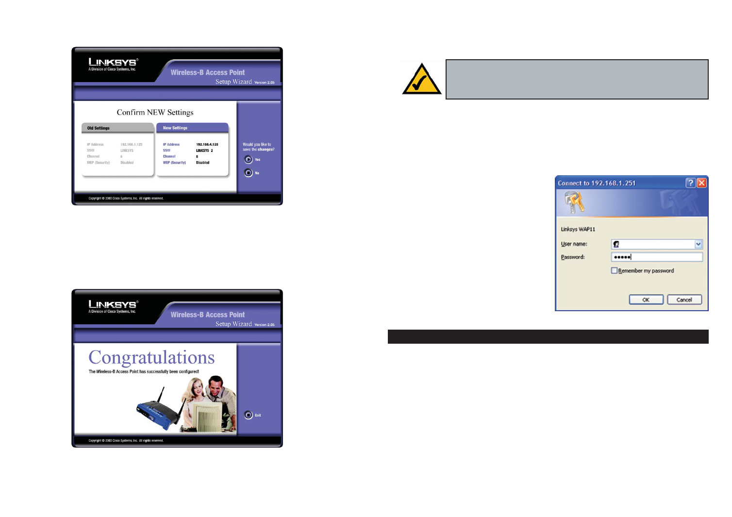
10. The next screen (Figure 5-9) will allow you to review your settings. If these
settings are correct, click the Ye s button to save these settings. If there are
any problems with the settings, click the No button to exit the Setup Wizard.
10. At this point, the configuration performed with the Setup Wizard is com-
plete, as shown in Figure 5-10. To configure any other access points in your
network, you can run this Setup Wizard again. Click the Exit button to exit
the Setup Wizard.
14
Chapter 6: Configuring the
Wireless-B Access Point
The Access Point has been designed to be functional right out of the box, with
the default settings in the Setup Wizard. However, if you’d like to change these
settings, the Access Point can be configured through your web browser with the
Web-based Utility. This chapter explains how to configure the Access Point in
this manner.
Open your web browser and type the
IP Address you entered in the Setup
Wizard (the default IP address is
192.168.1.251). Press the Enter key
and the following screen, shown in
Figure 6-1, will appear. Leave the
User Name field blank. The first time
you open the Web-based Utility, use
the default password admin. You can
set a new password on the Password
screen shown in Figure 6-7.
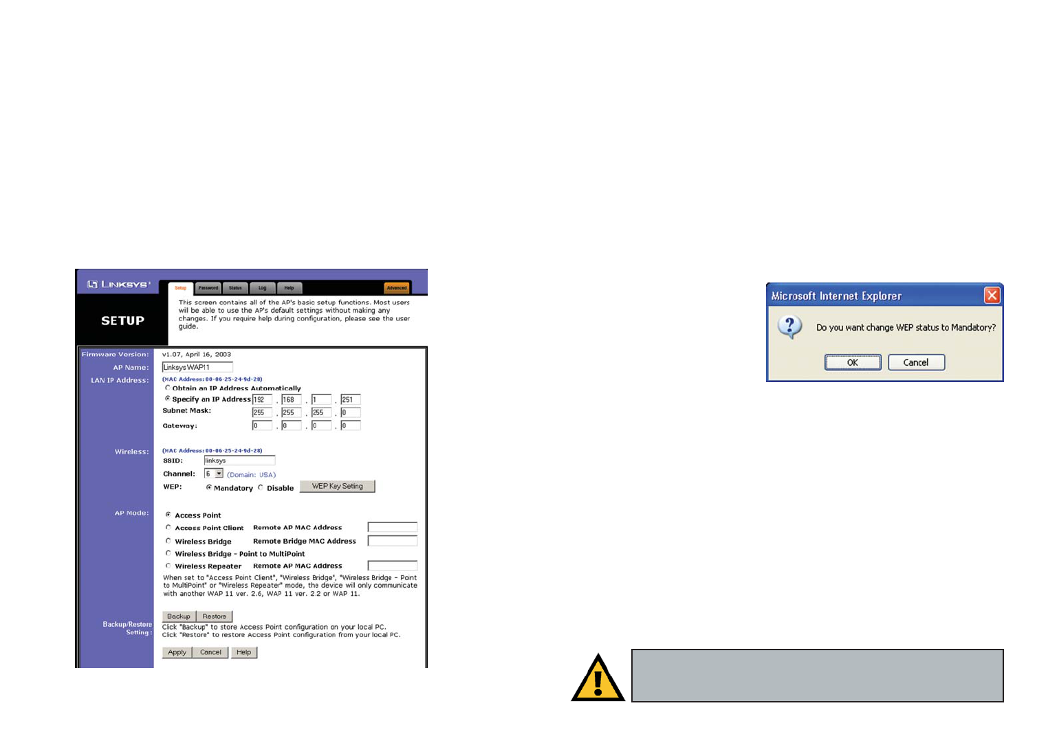
The first screen that appears, shown in Figure 6-2, is the Setup tab. This allows
you to change the Access Point’s general settings. Change these settings as
described here, and click the Apply button to apply your changes or Cancel to
cancel your changes. If you require online help, click the Help button.
• Firmware Version. This displays the current version of the Access Point’s
firmware. Firmware should only be upgraded if you experience problems
with the Access Point and can be upgraded from the Help tab.
• AP Name. You may assign any name to the Access Point. Unique, memo-
rable names are helpful, especially if you are employing multiple access
points on the same network. Verify this is the name you wish to use and
click the Apply button to set it.
Figure 6-1
The Setup Tab
Note: The Access Point is designed to function properly after
using the Setup Wizard. This chapter is provided solely for those
who wish to perform more advanced configuration or monitoring.
Figure 5-10
Figure 5-9
1716
• SSID. The SSID is the unique name shared among all devices in a wireless
network. The SSID must be identical for all devices in the wireless network.
It is case-sensitive and must not exceed 32 alphanumeric characters, which
may be any keyboard character.
• Channel. Select the appropriate channel from the list provided to corre-
spond with your network settings, between 1 and 11 (in North America). All
devices in your wireless network must use the same channel in order to
function correctly.
• WEP. The WEP Encryption method is set to Disable by default. To enable
WEP, click the Mandatory radio button, and then click the WEP Key
Setting button to configure the WEP settings.
SETTING WEP ENCRYPTION:
If the Disable radio button is selected and you click the WEP Key Setting but-
ton, then the screen shown in
Figure 6-3 will appear. Click the
OK button to enable WEP
encryption or Cancel to return to
the Setup screen.
Set WEP encryption through the
Web-based Utility by clicking the
WEP Key Setting button on the Setup screen as shown in Figure 6-2.
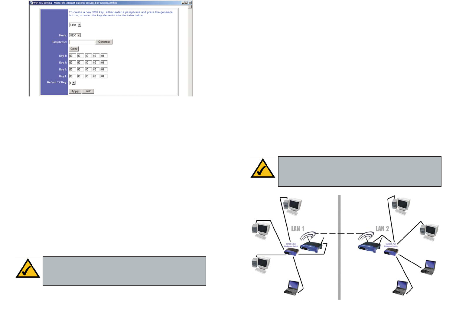
This will open the WEP Key Setting screen, Figure 6-4. From this screen, you
can select the type of WEP encryption to use and set the Passphrase for that
encryption.
From the pull-down menu at the top of the screen, select 64-bit or 128-bit WEP
encryption.
The Mode pull-down menu will allow you to set the Passphrase in hexadecimal
or ASCII characters. Hexadecimal characters on your keyboard are the letters
“A” through “F” and the numbers “0” through “9”, while ASCII characters are
any character on your keyboard.
Figure 6-3
Important: Always remember that each point in your wireless net-
work MUST use the same WEP encryption method and encryption
key, or else your wireless network will not function properly.
• Obtain an IP Address Automatically. Click this radio button to allow the
Access Point to obtain a dynamic IP address from a DHCP server.
• Specify an IP Address. This IP address must be unique to your network.
We suggest you use the default IP address of 192.168.1.251. As this is a pri-
vate IP address, there is no need to purchase a separate IP address from
your service provider. Verify the address and click the Apply button to save
changes.
• Subnet Mask. The Access Point’s Subnet Mask (or IP Mask) must be the
same as your Ethernet network. Verify this is correct and click the Apply
button to set it.
• Gateway. If you have assigned a static IP address to the Access Point, then
enter the IP address of your network’s Gateway, such as a router, in the
Gateway field. If your network does not have a Gateway, then leave this
field blank.
Figure 6-2
1918
• Access Point Client - When set to Access Point Client mode, the Access
Point Client is able to talk to one remote access point within its range. This
mode allows the Access Point Client to act as a client of a remote access
point. The Access Point Client cannot communicate directly with any wire-
less clients. A separate network attached to the Access Point Client can then
be wirelessly bridged to the remote access point. Enter the required LAN
MAC address of the remote access point in the Remote AP MAC Address
field.
• Wireless Bridge - If you are trying to make a wireless connection between
two wired networks, as shown in Figure 6-5, select Wireless Bridge. This
mode connects two physically separated wired networks with two access
points.
To configure a Wireless Bridge environment, click Wireless Bridge and
enter the LAN MAC address of the remote access point in the Remote
Bridge MAC Address field. The remote access point also needs to be set up
as a Wireless Bridge.
Note: All devices on each wired network must be connected through a hub
or switch.
Note: In Wireless Bridge mode, the Access Point can ONLY be
accessed by another access point in Wireless Bridge mode. In order
for your other wireless devices to access the Access Point, you must
reset it to Access Point mode. The two modes are mutually exclusive.
Figure 6-5
There are two ways to create WEP encryption keys. The first method is by typ-
ing a Passphrase into that field and clicking the Generate button. This will
generate WEP encryption keys based upon that passphrase. A second method
is to manually enter the WEP encryption keys in the available fields.
Click the Clear button to clear the Passphrase and Key 1-4 fields.
In the Default TX Key drop-down menu, select the number of the key you want
to use.
Click the Apply button to apply your changes, or click Undo to cancel your
most recent change.
SETTING THE AP MODE:
The Access Point offers five modes of operation: Access Point, Access Point
Client, Wireless Bridge, Wireless Bridge Point to MultiPoint, and Wireless
Repeater. For all bridging modes, as well as Wireless Repeater mode, make
sure the channel, SSID, and WEP keys are the same.
• Access Point - The Operational Mode is set to Access Point by default.
This connects your wireless PCs to a wired network. In most cases, no
change is necessary.
Figure 6-4
Note: For all modes of operation EXCEPT Access Point, the remote
access point must be a second Linksys Wireless-B Access Point
(WAP11). The Access Point will not communicate with any other
kind of remote access point.
To configure a Wireless Repeater environment, click Wireless Repeater
and enter the LAN MAC address of the remote access point in the Remote
AP MAC Address field.
• Backup and Restore. Clicking the Backup button will store the Access
Point’s configuration to your PC’s hard drive. You can restore this informa-
tion by clicking the Restore button.
Click the Apply button to apply your changes or Cancel to cancel your
changes. If you require online help, click the Help button.
21
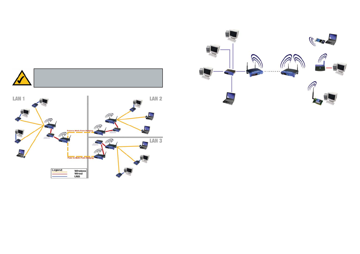
• Wireless Bridge Point to MultiPoint - If you are trying to make a wireless
connection between more than two wired networks, as shown in Figure 6-
6, select Wireless Bridge Point to MultiPoint. This mode allows you to
construct a network that has multiple access points bridging wirelessly.
To configure a Wireless Bridge Point to MultiPoint environment, click
Wireless Bridge Point to MultiPoint for the Access Point that will connect
to multiple access points (in Figure 6-6, it is the Access Point in LAN 1).
Then, for the other bridged access points, click Wireless Bridge, and enter
the Remote Bridge MAC Address of the Access Point set to Point to
MultiPoint.
• Wireless Repeater - When set to Wireless Repeater mode, the Wireless
Repeater is able to talk to one remote access point within its range and
retransmit its signal. See Figure 6-7.
20
Note: Linksys recommends bridging no more than three remote
LANs in Wireless Bridge Point to MultiPoint mode. Bridging addi-
tional remote LANs will result in a significant decrease in bandwidth.
Figure 6-6
Figure 6-7
23
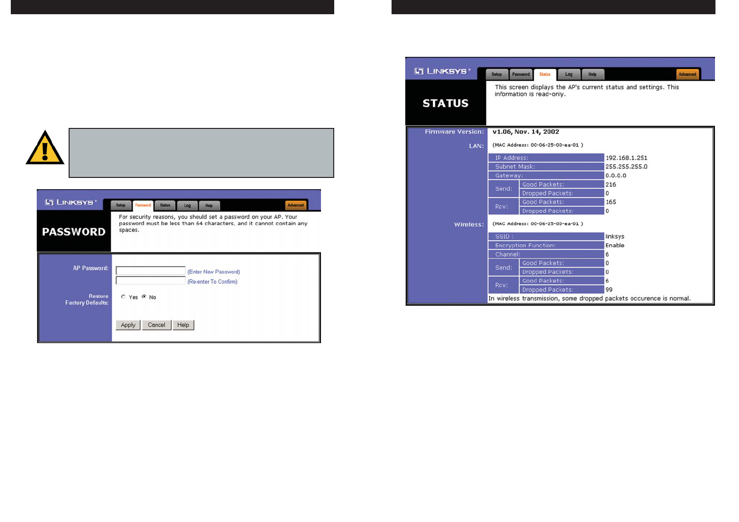
The Password tab, shown in Figure 6-8, allows you to change the Access Point’s
password and restore factory defaults.
Changing the password for the Access Point is as easy as typing the password
into the AP Password field. Then, type it again into the second field to confirm.
To restore the Access Point’s factory default settings, click the Ye s button
beside Restore Factory Defaults.
Click the Apply button to apply your changes or Cancel to cancel your
changes. If you require online help, click the Help button.
22
The Status tab, shown in Figure 6-9, will display current information on the
Access Point, its settings, and its performance.
• Firmware Version. This displays the current version of the Access Point’s
firmware. Firmware should only be upgraded if you experience problems
with the Access Point and can be upgraded from the Help tab.
LAN
• IP Address. This IP address is the unique IP address of the Access Point.
• Subnet Mask. The Access Point’s Subnet Mask (also known as an IP
Mask), matches the Subnet Mask of your Ethernet network.
Figure 6-9
The Status TabThe Password Tab
Important: Restoring the Access Point’s factory defaults will erase
all of your settings (WEP Encryption, Wireless and LAN settings,
etc.), replacing them with the factory defaults. Do not reset the
Access Point if you want to retain these settings
Figure 6-8
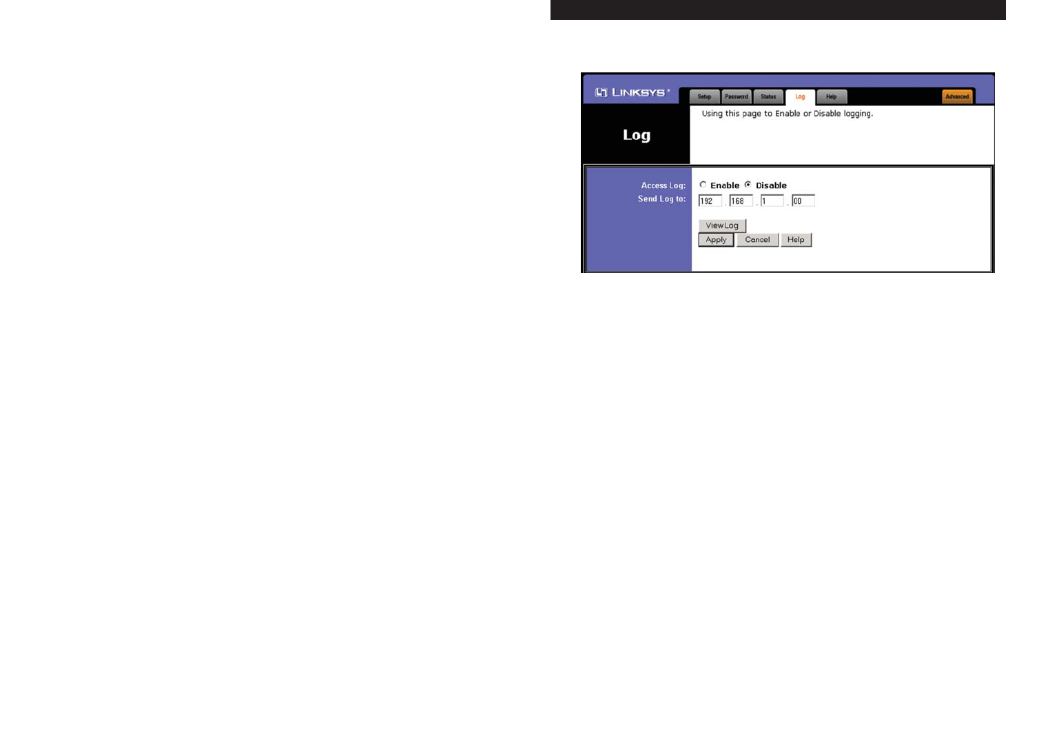
To view a log of the Access Point’s activity, select the Log tab, shown in Figure
6-10.
To enable permanent logging activity, click the Enable radio button beside
Access Log. The default setting for this function is Disable.
If you have chosen to monitor the Access Point’s traffic, then you can designate
a PC that will receive permanent log files periodically. In the Send Log to field,
enter the IP address of this PC. To view these permanent logs, you must use
Logviewer software, which can be downloaded free of charge from
www.linksys.com.
To see a temporary log of the Access Point’s most recent activities, click the
View Log button.
Click the Apply button to apply your changes or Cancel to cancel your
changes. If you require online help, click the Help button.
25
• Gateway. This displays the IP address of your network’s Gateway.
• Send and Recv. The Send and Recv fields display the number of success-
ful or dropped packets that have been sent or received.
Wireless
• SSID. The unique name shared among all devices in your wireless network
is displayed here.
• Encryption Function. The encryption method you chose in the Setup
Wizard or changed from the Setup tab of this Web-based Utility is displayed
here.
• Channel. The wireless channel shared by all wireless devices connected to
this Access Point is displayed here.
• Send and Recv. The Send and Recv fields display the number of success-
ful or dropped packets that have been sent or received. Some packet loss is
normal in wireless networking.
24
The Log Tab
Figure 6-10
New firmware versions are posted at www.linksys.com and can be downloaded
for free. If the Access Point is not experiencing difficulties, then there is no
need to download a more recent firmware version, unless that version has a
new feature that you want to use. Loading new firmware does not always
enhance the speed or quality of your Internet connection.
To upgrade the Access Point’s firmware:
1. Download the firmware upgrade file from the Linksys website.
2. Extract the firmware upgrade file.
3. Click the Upgrade Firmware button on the Help screen.
4. Enter the location of the firmware upgrade file in the File Path field, or
click the Browse button to find the firmware upgrade file.
5. Double-click the firmware upgrade file.
6. Click the Upgrade button, and follow the on-screen instructions.
Click the Cancel button to cancel the firmware upgrade.
To access the Filter tab, first click the Advanced tab. The Filter tab, shown in
Figure 6-12, allows you to control which computers may or may not commu-
nicate with the Access Point—depending on their MAC addresses.
To enable filtering of computers by their MAC addresses, click the Enable
radio button. To disable this feature, click the Disable radio button.
Next, determine if the Access Point will deny access only to the MAC address-
es you will specify, OR if the Access Point will allow access only to the MAC
addresses you will specify. Click the radio button next to the option that is
appropriate.
Above the MAC Address fields, there is a pull-down menu. For computers one
through ten on your wireless network, 1~10 is selected by default. If you have
more than ten computers on your wireless network, use this pull-down menu to
select 11~20, 21~30, etc., up to a maximum of 50 MAC addresses.
27
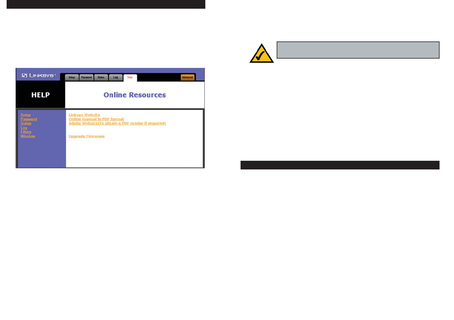
For help on the various tabs in this Web-based Utility, along with upgrading the
Access Point’s firmware and viewing this User Guide, click the Help tab,
shown in Figure 6-11.
The help files for the various tabs in this Web-based Utility are listed by tab
name on the lefthand side of the screen.
Click the Linksys Website link to connect to the Linksys homepage for
Knowledgebase help files and information about other Linksys products, pro-
vided you have an active Internet connection.
For an Online manual in PDF format, click that text link. The User Guide will
appear in Adobe pdf format. If you do not have the Adobe PDF Reader installed
on your computer, click the Adobe Website link or go to the Setup Wizard CD-
ROM to download this software. (To access the Adobe website, you will need an
active Internet connection.) To download from the CD-ROM, click the Start but-
ton and select Run. Type D:\Acrobat (if “D” is the letter of your CD-ROM drive).
26
The Filter Tab
Note: When you upgrade the Access Point’s firmware, you may
lose the Access Point’s current configuration settings.
The Help Tab
Figure 6-11
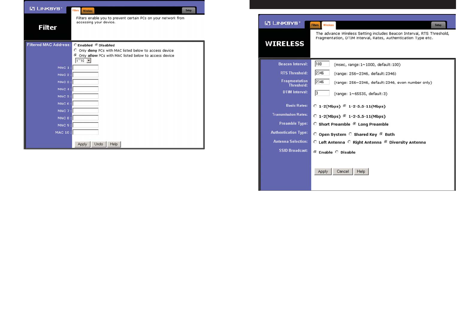
Before making any changes to the Wireless tab, shown in Figure 6-13, please
check your wireless settings on your other systems, as these changes will alter
the effectiveness of the Access Point. In most cases, these wireless settings do
not need to be changed.
• Beacon Interval. This value indicates the frequency interval of the beacon.
A beacon is a packet broadcast by the Access Point to keep the network syn-
chronized. A beacon includes the wireless LAN service area, the AP
address, the Broadcast destination addresses, a time stamp, Delivery Traffic
Indicator Maps, and the Traffic Indicator Message (TIM).
29
Then, type the MAC address(es) you wish to filter in the MAC Address fields.
When you’ve completed making any changes on this tab, click the Apply but-
ton to save those changes or Undo to cancel your changes. For more informa-
tion on this tab, click the Help button.
28
The Wireless Tab
Figure 6-13
Figure 6-12

• SSID Broadcast. For security purposes, this selection can be disabled,
allowing only those wireless network adapters with the Access Point’s SSID
to communicate with the Access Point. By default, this selection is enabled,
allowing all wireless network adapters in your wireless network to commu-
nicate with the Access Point.
When you’ve completed making any changes on this tab, click the Apply but-
ton to save those changes or Cancel to cancel your changes. For more infor-
mation on this tab, you can click the Help button.
3130
Important: The Access Point will not be recognized by “site-sur-
vey” utilities, such as the Microsoft®Windows®XP Zero
Configuration Utility, if SSID Broadcast is disabled.
• RTS Threshold. This value should remain at its default setting of 2346.
Should you encounter inconsistent data flow, only minor reductions are rec-
ommended.
• Fragmentation Threshold. This value specifies the maximum size for a
packet before data is fragmented into multiple packets. It should remain at
its default setting of 2346. A smaller setting means smaller packets, which
will create more packets for each transmission. Only minor reductions of
this value are recommended.
• DTIM Interval. This value indicates the interval of the Delivery Traffic
Indication Message (DTIM). A DTIM field is a countdown field informing
clients of the next window for listening to broadcast and multicast mes-
sages. When the Access Point has buffered broadcast or multicast messages
for associated clients, it sends the next DTIM with a DTIM Interval value.
Access Point Clients hear the beacons and awaken to receive the broadcast
and multicast messages.
• Basic Rates. The basic rate is the minimum speed at which a wireless client
is allowed to connect to the Access Point.
• Transmission Rates. The transmission rates should be set depending on the
speed of your wireless network. You must select 1-2 (Mbps) if you have
older 802.11 compliant equipment on your network, such as wireless
adapters that support only 1 or 2 Mbps. Selecting 1-2 (Mbps), however,
does NOT limit the transmission rates of faster adapters.
• Preamble Type. The preamble defines the length of the CRC block for
communication between the Access Point and a roaming wireless network
adapter. (High network traffic areas should use the shorter preamble type.)
Select the appropriate preamble type and click the Apply button to set it.
All wireless devices on your network should use the same preamble type.
• Authentication Type. You may choose between Open System, Shared
Key, and Both. The Authentication Type default is set to Open System.
Shared Key is when both the sender and the recipient share a secret key. All
devices on your network must use the same authentication type. It is rec-
ommended that you use the default setting, Both.
• Antenna Selection. This selection is for choosing which antenna transmits
data. By default, the Diversity Antenna selection, used to increase recep-
tion, is chosen.

3332
What IEEE 802.11b features are supported?
The product supports the following IEEE 802.11 functions:
• CSMA/CA plus Acknowledge protocol
• Multi-Channel Roaming
• Automatic Rate Selection
• RTS/CTS feature
• Fragmentation
• Power Management
What is ad-hoc mode?
When a wireless network is set to ad-hoc mode, the wireless-equipped com-
puters are configured to communicate directly with each other. The ad-hoc
wireless network will not communicate with any wired network.
What is infrastructure mode?
When a wireless network is set to infrastructure mode, the wireless network is
configured to communicate with a wired network through a wireless access
point.
What is roaming?
Roaming is the ability of a portable computer user to communicate continu-
ously while moving freely throughout an area greater than that covered by a
single wireless network access point. Before using the roaming function, the
workstation must make sure that it is the same channel number as the wireless
network access point of the dedicated coverage area.
To achieve true seamless connectivity, the wireless LAN must incorporate a
number of different functions. Each node and wireless network access point,
for example, must always acknowledge receipt of each message. Each node
must maintain contact with the wireless network even when not actually trans-
mitting data. Achieving these functions simultaneously requires a dynamic RF
networking technology that links wireless network access points and nodes. In
such a system, the user’s end node undertakes a search for the best possible
access to the system. First, it evaluates such factors as signal strength and qual-
ity, as well as the message load currently being carried by each wireless net-
work access point and the distance of each wireless network access point to the
wired backbone. Based on that information, the node next selects the right
wireless network access point and registers its address. Communications
between end node and host computer can then be transmitted up and down the
backbone.
Appendix A: Troubleshooting
This chapter provides a list of questions and answers regarding the operation of
the Access Point. Read the description below to solve your problems. If you
can’t find an answer here, check the Linksys website at www.linksys.com.
1. I am getting interference between my 2.4GHz phone system and my wireless
network.
There are a few steps you can take:
• Change the channel of the phone or the Access Point so they use different
channels.
• Move the phone’s base station so that it’s farther away from the Access Point.
• If there is still too much interference, you may have to buy a different phone
system, either 900MHz or 5GHz.
1. I need to extend the range of my wireless network.
Set the Access Point to Wireless Repeater mode, and buy a second Wireless-
B Access Point (WAP11), which will re-transmit the first Access Point’s sig-
nal.
Can the Access Point act as my DHCP Server?
No. The Access Point is nothing more than a wireless hub, and as such, cannot
be configured to handle DHCP capabilities.
Can I run an application from a remote computer over the wireless network?
This will depend on whether or not the application is designed to be used over
a network. Consult the application’s user guide to determine if it supports oper-
ation over a network.
Can I play multiplayer games with other users of the wireless network?
Yes, as long as the game supports multiple players over a LAN (local area net-
work). Refer to the game’s user guide for more information.
What is the IEEE 802.11b standard?
It is one of the IEEE standards for wireless networks. The 802.11b standard
allows wireless networking hardware from different manufacturers to commu-
nicate, provided that the hardware complies with the 802.11b standard. The
802.11b standard states a maximum data transfer rate of 11Mbps and an oper-
ating frequency of 2.4GHz.
Common Problems and Solutions
Frequently Asked Questions

Would the information be intercepted while transmitting on air?
Linksys wireless products feature two-fold protection in security. On the hard-
ware side, as with Direct Sequence Spread Spectrum technology, it has the
inherent security feature of scrambling. On the software side, Linksys wireless
products offer the encryption function (WEP) to enhance security and access
control. Users can set it up depending upon their needs.
Can Linksys wireless products support file and printer sharing?
Linksys wireless products perform the same function as LAN products.
Therefore, they can work with NetWare, Windows NT/2000, or other LAN
operating systems to support printer or file sharing.
What is WEP?
WEP is Wired Equivalent Privacy, a data privacy mechanism based on a 40/64
bit shared key algorithm, as described in the IEEE 802.11 standard.
What is a MAC Address?
The Media Access Control (MAC) address is a unique number assigned by the
manufacturer to any Ethernet networking device, such as a network adapter,
that allows the network to identify it at the hardware level. For all practical pur-
poses, this number is usually permanent. Unlike IP addresses, which can
change every time a computer logs on to the network, the MAC address of a
device stays the same, making it a valuable identifier for the network.
35
As the user moves on, the end node’s RF transmitter regularly checks the sys-
tem to determine whether it is in touch with the original wireless network
access point or whether it should seek a new one. When a node no longer
receives acknowledgment from its original wireless network access point, it
undertakes a new search. Upon finding a new wireless network access point, it
then re-registers, and the communication process continues.
What is ISM band?
The FCC and their counterparts outside of the U.S. have set aside bandwidth
for unlicensed use in the ISM (Industrial, Scientific and Medical) band.
Spectrum in the vicinity of 2.4 GHz, in particular, is being made available
worldwide. This presents a truly revolutionary opportunity to place convenient
high speed wireless capabilities in the hands of users around the globe.
What is Spread Spectrum?
Spread Spectrum technology is a wideband radio frequency technique devel-
oped by the military for use in reliable, secure, mission-critical communica-
tions systems. It is designed to trade off bandwidth efficiency for reliability,
integrity, and security. In other words, more bandwidth is consumed than in the
case of narrowband transmission, but the trade-off produces a signal that is, in
effect, louder and thus easier to detect, provided that the receiver knows the
parameters of the spread-spectrum signal being broadcast. If a receiver is not
tuned to the right frequency, a spread-spectrum signal looks like background
noise. There are two main alternatives, Direct Sequence Spread Spectrum
(DSSS) and Frequency Hopping Spread Spectrum (FHSS).
What is DSSS? What is FHSS? And what are their differences?
Frequency Hopping Spread Spectrum (FHSS) uses a narrowband carrier that
changes frequency in a pattern that is known to both transmitter and receiver.
Properly synchronized, the net effect is to maintain a single logical channel. To
an unintended receiver, FHSS appears to be short-duration impulse noise.
Direct Sequence Spread Spectrum (DSSS) generates a redundant bit pattern for
each bit to be transmitted. This bit pattern is called a chip (or chipping code).
The longer the chip, the greater the probability that the original data can be
recovered. Even if one or more bits in the chip are damaged during transmis-
sion, statistical techniques embedded in the radio can recover the original data
without the need for retransmission. To an unintended receiver, DSSS appears
as low power wideband noise and is rejected (ignored) by most narrowband
receivers.
34

The following instructions are provided as examples for reference only. For
complete instructions on installing and troubleshooting TCP/IP, consult your
Windows operating system documentation.
1. Click the Start button, and select Settings. Open the Control Panel. Inside
the Control Panel, double-click the Network icon.
2. If the TCP/IP Protocol is listed for your network adapter, go to step five.
Otherwise, click the Add button.
3. When the Component Type window appears, select Protocol, and click the
Add button.
4. Select Microsoft in the Manufacturers list and choose TCP/IP in the
Network Protocols list. Then, click the OK button.
5. When the Network window reappears, click TCP/IP, and then click the
Properties button.
6. Select Specify an IP Address.
7. Enter an IP Address for the computer, along with a Subnet Mask. Click the
OK button. If you do not have these values, consult your network adminis-
trator.
8. When the Network window reappears, click the OK button. Restart your
machine. TCP/IP has now been successfully installed.
3736
TCP/IP Setup for Windows 98 and Millennium
Appendix B: Setting Up the TCP/IP
Protocol
Before a computer can communicate with the Access Point, it must be config-
ured with the TCP/IP protocol. If you know how to set up TCP/IP on your com-
puters, do so now. Otherwise, use the guidelines below to help get TCP/IP
installed on all of the computers that need to communicate with the Access
Point. If you are unable to successfully install TCP/IP on one or more comput-
ers after following the directions, contact the manufacturer of your computer’s
network operating system for further assistance. Check with your network
administrator for your TCP/IP settings.
The directions below provide general guidelines for coming up with IP address-
es and subnet masks. Check with your network administrator to see if you need
to use specific IP addresses or DHCP settings.
First, each computer on the network will require an IP address, which is a series
of numbers, separated by periods, identifying the PC on the network. To make
things simple, it is recommended you use the following numbering scheme:
192.168.1.X
In this example, X is a unique, arbitrarily assigned number from 1 to 254. Each
computer must have its own unique X number. Note: Never use 0 or 255 for X.
These numbers are reserved by TCP/IP for other uses.
For example, if you have three computers, you could number them as follows:
192.168.1.17
192.168.1.44
192.168.1.126
In this case, 17, 44, and 126 are arbitrary numbers between 1 and 254.
Each computer will also require a subnet mask, which is a numerical “filter”
that tells a computer what kinds of TCP/IP data packets to accept. If you’re not
sure which mask to use, the following mask is recommended:
255.255.255.0
Setting Up TCP/IP in Windows

1. At the Windows XP desktop, click Start. Then click the Control Panel
icon. Click Network and Internet Connections. Click Network
Connections. Then double-click the appropriate Local Area Connection,
and click the Properties button.
2. If the TCP/IP Protocol is listed for your network adapter, go to step five.
Otherwise, click the Install button.
3. Select Protocol, and then click the Add button.
4. Select Internet Protocol (TCP/IP) from the list, and click the OK button.
5. Select TCP/IP, and click the Properties button.
6. Select Use the following IP Address.
7. Enter an IP address for the computer, along with a Subnet mask and Default
gateway address. Then, click the OK button. If you do not have these val-
ues, consult your network administrator.
8. When you’re finished, click the Close button. Restart your computer.
TCP/IP has now been successfully installed.
39
1. At the Windows 2000 desktop, right-click My Network Places. Then,
right-click Local Area Connection. Choose Properties.
2. If the TCP/IP Protocol is listed for your network adapter, go to step five.
Otherwise, click the Install button.
3. When the Component Type window appears, select Protocol, and click the
Install button.
4. Select Internet Protocol (TCP/IP) from the list, and click the OK button.
5. When the Network window reappears, select TCP/IP, and click the
Properties button.
6. Select Use the following IP Address.
7. Enter an IP Address for the computer, along with a Subnet Mask and
Default Gateway. Then, click the OK button. If you do not have these val-
ues, consult your network administrator.
8. When the Network window reappears, click the OK button. Restart your
computer. TCP/IP has now been successfully installed.
38
TCP/IP Setup for Windows XPTCP/IP Setup for Windows 2000

4140
being held up by the other. In order for a buffer to be effective, the size of the
buffer and the algorithms for moving data into and out of the buffer need to be
considered by the buffer designer. Like a cache, a buffer is a "midpoint holding
place” but exists not so much to accelerate the speed of an activity as to sup-
port the coordination of separate activities.
CSMA/CA (Carrier Sense Multiple Access/Collision Avoidance) - In local
area networking, this is the CSMA technique that combines slotted time-divi-
sion multiplexing with carrier sense multiple access/collision detection
(CSMA/CD) to avoid having collisions occur a second time. This works best if
the time allocated is short compared to packet length and if the number of sit-
uations is small.
CSMA/CD (Carrier Sense Multiple Access/Collision Detection) - The LAN
access method used in Ethernet. When a device wants to gain access to the net-
work, it checks to see if the network is quiet (senses the carrier). If it is not, it
waits a random amount of time before retrying. If the network is quiet and two
devices access the line at exactly the same time, their signals collide. When the
collision is detected, they both back off and each wait a random amount of time
before retrying.
Database - A database is a collection of data that is organized so that its con-
tents can easily be accessed, managed, and updated.
DHCP (Dynamic Host Configuration Protocol) - A protocol that lets network
administrators manage centrally and automate the assignment of Internet
Protocol (IP) addresses in an organization's network. Using the Internet's set of
protocol (TCP/IP), each machine that can connect to the Internet needs a
unique IP address. When an organization sets up its computer users with a con-
nection to the Internet, an IP address must be assigned to each machine.
Without DHCP, the IP address must be entered manually at each computer and,
if computers move to another location in another part of the network, a new IP
address must be entered. DHCP lets a network administrator supervise and dis-
tribute IP addresses from a central point and automatically sends a new IP
address when a computer is plugged into a different place in the network.
DHCP uses the concept of a “lease” or amount of time that a given IP address
will be valid for a computer. The lease time can vary depending on how long a
user is likely to require the Internet connection at a particular location. It's espe-
cially useful in education and other environments where users change fre-
quently. Using very short leases, DHCP can dynamically reconfigure networks
in which there are more computers than there are available IP addresses.
Appendix C: Glossary
Adapter - Printed circuit board that plugs into a PC to add to capabilities or
connectivity to a PC. In a networked environment, a network interface card is
the typical adapter that allows the PC or server to connect to the intranet and/or
Internet.
Ad-hoc Network - An ad-hoc network is a group of computers, each with a
wireless adapter, connected as an independent 802.11 wireless LAN. Ad-hoc
wireless computers operate on a peer-to-peer basis, communicating directly
with each other without the use of an access point. Ad-hoc mode is also
referred to as an Independent Basic Service Set (IBSS) or as peer-to-peer
mode, and is useful at a departmental scale or SOHO operation.
Backbone - The part of a network that connects most of the systems and net-
works together and handles the most data.
Bandwidth - The transmission capacity of a given facility, in terms of how
much data the facility can transmit in a fixed amount of time; expressed in bits
per second (bps).
Beacon Interval - A beacon is a packet broadcast by the Access Point to keep
the network synchronized. A beacon includes the wireless LAN service area,
the AP address, the Broadcast destination addresses, a time stamp, Delivery
Traffic Indicator Maps, and the Traffic Indicator Message (TIM).
Bit - A binary digit. The value - 0 or 1-used in the binary numbering system.
Also, the smallest form of data.
Browser - A browser is an application program that provides a way to look at
and interact with all the information on the World Wide Web or PC. The word
“browser” seems to have originated prior to the Web as a generic term for user
interfaces that let you browse text files online.
BSS (Basic Service Set) - An infrastructure network connecting wireless
devices to a wired network using a single access point.
Buffer - A buffer is a shared or assigned memory area used by hardware
devices or program processes that operate at different speeds or with different
sets of priorities. The buffer allows each device or process to operate without

4342
10 Mbps. Forms the underlying transport vehicle used by several upper-level
protocols, including TCP/IP and XNS.
FHSS (Frequency Hopping Spread Spectrum) - FHSS continuously changes
the center frequency of a conventional carrier several times per second accord-
ing to a pseudo-random set of channels, while chirp spread spectrum changes
the carrier frequency. Because a fixed frequency is not used, illegal monitoring
of spread spectrum signals is extremely difficult, if not downright impossible
depending on the particular method.
Firmware - Code that is written onto read-only memory (ROM) or program-
mable read-only memory (PROM). Once firmware has been written onto the
ROM or PROM, it is retained even when the device is turned off.
Fragmentation - Breaking a packet into smaller units when transmitting over
a network medium that cannot support the original size of the packet.
Gateway - A device that interconnects networks with different, incompatible
communications protocols.
Hardware - Hardware is the physical aspect of computers, telecommunica-
tions, and other information technology devices. The term arose as a way to dis-
tinguish the “box” and the electronic circuitry and components of a computer
from the program you put in it to make it do things. The program came to be
known as the software.
Hub - The device that serves as the central location for attaching wires from
workstations. Can be passive, where there is no amplification of the signals; or
active, where the hubs are used like repeaters to provide an extension of the
cable that connects to a workstation.
IEEE (The Institute of Electrical and Electronics Engineers) - The IEEE
describes itself as “the world's largest technical professional society, promoting
the development and application of electrotechnology and allied sciences for
the benefit of humanity, the advancement of the profession, and the well-being
of our members.”
The IEEE fosters the development of standards that often become national and
international standards. The organization publishes a number of journals, has
many local chapters, and several large societies in special areas, such as the
IEEE Computer Society.
DHCP supports static addresses for computers containing Web servers that
need a permanent IP address.
Download - To receive a file transmitted over a network. In a communications
session, download means receive, upload means transmit.
Driver - A workstation or server software module that provides an interface
between a device and the upper-layer protocol software running in the comput-
er; it is designed for a specific device, and is installed during the initial instal-
lation of a network-compatible client or server operating system.
DSSS (Direct-Sequence Spread-Spectrum) - DSSS generates a redundant bit
pattern for all transmitted data. This bit pattern is called a chip (or chipping
code). Even if one or more bits in the chip are damaged during transmission,
statistical techniques embedded in the receiver can recover the original data
without the need for retransmission. To an unintended receiver, DSSS appears
as low power wideband noise and is rejected (ignored) by most narrowband
receivers. However, to an intended receiver (i.e. another wireless LAN end-
point), the DSSS signal is recognized as the only valid signal, and interference
is inherently rejected (ignored).
DTIM (Delivery Traffic Indication Message) - A DTIM field is a countdown
field informing clients of the next window for listening to broadcast and mul-
ticast messages. When the AP has buffered broadcast or multicast messages for
associated clients, it sends the next DTIM with a DTIM Interval value. AP
Clients hear the beacons and awaken to receive the broadcast and multicast
messages.
Dynamic IP Address - An IP address that is automatically assigned to a client
station in a TCP/IP network, typically by a DHCP server. Network devices that
serve multiple users, such as servers and printers, are usually assigned static IP
addresses.
Encryption - A security method that applies a specific algorithm to data in
order to alter the data's appearance and prevent other devices from reading the
information.
ESS (Extended Service Set) - A set of more than two or more BSSs (multiple
access points) forming a single network.
Ethernet - IEEE standard network protocol that specifies how data is placed
on and retrieved from a common transmission medium. Has a transfer rate of

Network - A system that transmits any combination of voice, video and/or data
between users.
Node - A network junction or connection point, typically a computer or work
station.
Packet - A unit of data routed between an origin and a destination in a network.
Passphrase - Used much like a password, a passphrase simplifies the WEP
encryption process by automatically generating the WEP encryption keys for
Linksys products.
PC Card - A credit-card sized removable module that contains memory, I/O,
or a hard disk.
Port - A pathway into and out of the computer or a network device such as a
switch or router. For example, the serial and parallel ports on a personal com-
puter are external sockets for plugging in communications lines, modems and
printers.
RJ-45 (Registered Jack-45) - A connector similar to a telephone connector that
holds up to eight wires, used for connecting Ethernet devices.
Roaming - In an infrastructure mode wireless network, this refers to the abili-
ty to move out of one access point's range and into another and transparently
reassociate and reauthenticate to the new access point. This reassociation and
reauthentication should occur without user intervention and ideally without
interruption to network connectivity. A typical scenario would be a location
with multiple access points, where users can physically relocate from one area
to another and easily maintain connectivity.
Router - Protocol-dependent device that connects subnetworks together.
Routers are useful in breaking down a very large network into smaller subnet-
works; they introduce longer delays and typically have much lower throughput
rates than bridges.
RTS (Request To Send) - An RS-232 signal sent from the transmitting station
to the receiving station requesting permission to transmit.
Server - Any computer whose function in a network is to provide user access
to files, printing, communications, and other services.
4544
Infrastructure Network - An infrastructure network is a group of computers
or other devices, each with a wireless adapter, connected as an 802.11 wireless
LAN. In infrastructure mode, the wireless devices communicate with each
other and to a wired network by first going through an access point. An infra-
structure wireless network connected to a wired network is referred to as a
Basic Service Set (BSS). A set of two or more BSS in a single network is
referred to as an Extended Service Set (ESS). Infrastructure mode is useful at
a corporation scale, or when it is necessary to connect the wired and wireless
networks.
IP Address - In the most widely installed level of the Internet Protocol
(Internet Protocol) today, an IP address is a 32-binary digit number that identi-
fies each sender or receiver of information that is sent in packet across the
Internet. When you request an HTML page or send e-mail, the Internet
Protocol part of TCP/IP includes your IP address in the message (actually, in
each of the packets if more than one is required) and sends it to the IP address
that is obtained by looking up the domain name in the Uniform Resource
Locator you requested or in the e-mail address you're sending a note to. At the
other end, the recipient can see the IP address of the Web page requestor or the
e-mail sender and can respond by sending another message using the IP address
it received.
ISM band - The FCC and their counterparts outside of the U.S. have set aside
bandwidth for unlicensed use in the ISM (Industrial, Scientific and Medical)
band. Spectrum in the vicinity of 2.4 GHz, in particular, is being made avail-
able worldwide. This presents a truly revolutionary opportunity to place con-
venient high-speed wireless capabilities in the hands of users around the globe.
LAN - A local area network (LAN) is a group of computers and associated
devices that share a common communications line and typically share the
resources of a single processor or server within a small geographic area (for
example, within an office building).
MAC (Media Access Control) Address - A unique number assigned by the
manufacturer to any Ethernet networking device, such as a network adapter,
that allows the network to identify it at the hardware level.
Mbps (MegaBits Per Second) - One million bits per second; unit of measure-
ment for data transmission.
Multicasting - Sending data to a group of nodes instead of a single destination.

between network devices over a LAN or WAN. While IP takes care of handling
the actual delivery of the data (routing), TCP takes care of keeping track of the
individual units of data (called packets) that a message is divided into for effi-
cient delivery over the network. TCP is known as a "connection oriented" pro-
tocol due to requiring the receiver of a packet to return an acknowledgment of
receipt to the sender of the packet resulting in transmission control.
TCP/IP (Transmission Control Protocol/Internet Protocol) - The basic com-
munication language or set of protocols for communications over a network
(developed specifically for the Internet). TCP/IP defines a suite or group of
protocols and not only TCP and IP.
Throughput - The amount of data moved successfully from one place to anoth-
er in a given time period.
Topology - A network's topology is a logical characterization of how the
devices on the network are connected and the distances between them. The
most common network devices include hubs, switches, routers, and gateways.
Most large networks contain several levels of interconnection, the most impor-
tant of which include edge connections, backbone connections, and wide-area
connections.
Upgrade - To replace existing software or firmware with a newer version.
Upload - To transmit a file over a network. In a communications session,
upload means transmit, download means receive.
UTP - Unshielded twisted pair is the most common kind of copper telephone
wiring. Twisted pair is the ordinary copper wire that connects home and many
business computers to the telephone company. To reduce crosstalk or electro-
magnetic induction between pairs of wires, two insulated copper wires are
twisted around each other. Each signal on twisted pair requires both wires.
Since some telephone sets or desktop locations require multiple connections,
twisted pair is sometimes installed in two or more pairs, all within a single
cable.
WEP (Wired Equivalent Privacy) - A data privacy mechanism based on a 64-
bit, 128-bit, or 256-bit shared key algorithm, as described in the IEEE 802.11
standard.
47
Software - Instructions for the computer. A series of instructions that performs
a particular task is called a “program.” The two major categories of software are
“system software” and “application software.” System software is made up of
control programs such as the operating system and database management sys-
tem (DBMS). Application software is any program that processes data for the
user.
A common misconception is that software is data. It is not. Software tells the
hardware how to process the data.
SOHO (Small Office/Home Office) - Market segment of professionals who
work at home or in small offices.
Spread Spectrum - Spread Spectrum technology is a wideband radio frequen-
cy technique developed by the military for use in reliable, secure, mission-crit-
ical communications systems. It is designed to trade off bandwidth efficiency
for reliability, integrity, and security. In other words, more bandwidth is con-
sumed than in the case of narrowband transmission, but the trade off produces
a signal that is, in effect, louder and thus easier to detect, provided that the
receiver knows the parameters of the spread-spectrum signal being broadcast.
If a receiver is not tuned to the right frequency, a spread-spectrum signal looks
like background noise. There are two main alternatives, Direct Sequence
Spread Spectrum (DSSS) and Frequency Hopping Spread Spectrum (FHSS).
SSID (Service Set Identifier) - A unique name shared among all points in a
wireless network. The SSID must be identical for each point in the wireless
network and is case-sensitive. Also known as “ESSID.”
Static IP Address - A permanent IP address that is assigned to a node in an IP
or a TCP/IP network.
Subnet Mask - The method used for splitting IP networks into a series of sub-
groups, or subnets. The mask is a binary pattern that is matched up with the IP
address to turn part of the host ID address field into a field for subnets.
Switch - 1. A data switch connects computing devices to host computers,
allowing a large number of devices to share a limited number of ports. 2. A
device for making, breaking, or changing the connections in an electrical cir-
cuit.
TCP (Transmission Control Protocol) - A method (protocol) used along with
the IP (Internet Protocol) to send data in the form of message units (datagram)
46

49
Appendix E: Warranty Information
BE SURE TO HAVE YOUR PROOF OF PURCHASE AND A BARCODE
FROM THE PRODUCT’S PACKAGING ON HAND WHEN CALLING.
RETURN REQUESTS CANNOT BE PROCESSED WITHOUT PROOF OF
PURCHASE.
IN NO EVENT SHALL LINKSYS’S LIABILITY EXCEED THE PRICE
PAID FOR THE PRODUCT FROM DIRECT, INDIRECT, SPECIAL, INCI-
DENTAL, OR CONSEQUENTIAL DAMAGES RESULTING FROM THE
USE OF THE PRODUCT, ITS ACCOMPANYING SOFTWARE, OR ITS
DOCUMENTATION. LINKSYS DOES NOT OFFER REFUNDS FOR ANY
PRODUCT.
LINKSYS OFFERS CROSS SHIPMENTS, A FASTER PROCESS FOR PRO-
CESSING AND RECEIVING YOUR REPLACEMENT. LINKSYS PAYS
FOR UPS GROUND ONLY. ALL CUSTOMERS LOCATED OUTSIDE OF
THE UNITED STATES OF AMERICA AND CANADA SHALL BE HELD
RESPONSIBLE FOR SHIPPING AND HANDLING CHARGES. PLEASE
CALL LINKSYS FOR MORE DETAILS.
Appendix D: Specifications
Standards 802.11b, 802.3, 802.3u
Port One 10/100 RJ-45 Port
Button 1 x Reset Button
Cabling Type RJ-45
LEDs 1 x Power, 1 x Activity, 1 x Link
Transmit Power 15 dBm @ Normal Temp Range
Security Features MAC filtering, WEP,
SSID Broadcast enable/disable
WEP Key Bits 64/128-bit
Dimensions 7.32" x 1.89" x 6.89" (186 mm x 48 mm x 175 mm)
Weight 11.00 oz. (0.31 kg)
PowerExternal,DC 12V
CertificationsFCC
Operating Temp. 0ºC to 40ºC
Storage Temp. -20ºC to 70ºC
Operating Humidity 10% to 85%, Non-Condensing
Storage Humidity 5% to 90%, Non-Condensing
48
Environmental
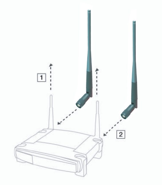
Also Available:
·
Linksys High Gain Antenna for TNC Connectors (HG5T)

© Copyright 2003 Cisco Systems Inc. All rights reserved.
http://www.linksys.com
50
Appendix F: Contact Information
For help with the installation or operation of this product, contact Linksys
Technical Support at one of the phone numbers or Internet addresses below.
Sales Information 800-546-5797 (LINKSYS)
Technical Support 800-326-7114
RMA (Return Merchandise
Authorization) Issues www.linksys.com (or call 949-271-5461)
Fax 949-265-6655
E-mail support@linksys.com
Web http://www.linksys.com
FTP Site ftp.linksys.com