LINKSYS HGA7S-WMP54GX Wireless-G PCI Adapter with SRX User Manual Book
LINKSYS LLC Wireless-G PCI Adapter with SRX Book
LINKSYS >
Contents
- 1. Users Manual 1
- 2. Users Manual 2
- 3. Users Manual 3
- 4. Users Manual 4
Users Manual 1
A Division of Cisco Systems, Inc.
®
Model No.
PCI Adapter with SRX
Wireless-G
WMP54GX
User Guide
WIRELESS
GHz
2.4
802.11g
Also Available:
Linksys High Gain Antenna for SMA Connectors (HGA7S)

Wireless-G PCI Adapter with SRX
Copyright and Trademarks
Specifications are subject to change without notice. Linksys is a registered trademark or trademark of Cisco
Systems, Inc. and/or its affiliates in the U.S. and certain other countries. Copyright © 2005 Cisco Systems, Inc. All
rights reserved. Other brands and product names are trademarks or registered trademarks of their respective
holders.
How to Use This User Guide
This User Guide has been designed to make understanding networking with the Wireless-G PCI Adapter easier
than ever. Look for the following items when reading this User Guide:
In addition to these symbols, there are definitions for technical terms that are presented like this:
Also, each figure (diagram, screenshot, or other image) is provided with a figure number and description, like
this:
Figure numbers and descriptions can also be found in the “List of Figures” section in the “Table of Contents”.
This exclamation point means there is a caution or warning and is
something that could damage your property or the Wireless-G PCI Adapter.
This checkmark means there is a note of interest and is something you
should pay special attention to while using the Wireless-G PCI Adapter.
This question mark provides you with a reminder about something you
might need to do while using the Wireless-G PCI Adapter.
word: definition.
Figure 0-1: Sample Figure Description
WMP54GX-UG-50518NC JL
WARNING: This product contains chemicals, including lead, known
to the State of California to cause cancer, and birth defects or other
reproductive harm. Wash hands after handling.

Wireless-G PCI Adapter with SRX
Table of Contents
Chapter 1: Introduction 1
Welcome 1
What’s in This User Guide? 1
Chapter 2: Planning Your Wireless Network 3
Network Topology 3
Roaming 3
Network Layout 4
Chapter 3: Getting to Know the Wireless-G Notebook Adapter with SRX 5
Overview 5
The LED Indicator 5
The Cable Connectors 5
Chapter 4: Setting Up and Connecting the Wireless-G PCI Adapter with SRX 6
Starting the Setup Wizard 6
Installing the Adapter 7
Setting Up the Adapter 8
Chapter 5: Using the Wireless Network Monitor 18
Accessing the Wireless Network Monitor 18
Link Information Screens 18
Site Survey 21
Profiles 23
Creating a New Profile 24
Appendix A: Troubleshooting 34
Common Problems and Solutions 34
Frequently Asked Questions 35
Appendix B: Using Windows XP Wireless Zero Configuration 38
Appendix C: Wireless Security 41
Security Precautions 41
Security Threats Facing Wireless Networks 41
Appendix D: Windows Help 44
Appendix E: Glossary 45
Appendix F: Specifications 48

Wireless-G PCI Adapter with SRX
Appendix G: Warranty Information 50
Appendix H: Regulatory Information 51
Appendix I: Contact Information 53

Wireless-G PCI Adapter with SRX
List of Figures
Figure 3-1: Adapter’s LED 5
Figure 3-2: Adapter’s Connectors for the Antenna Cables 5
Figure 4-1: Setup Wizard’s Welcome Screen 6
Figure 4-2: Setup Wizard’s License Agreement 6
Figure 4-3: Connecting the Adapter Screen 7
Figure 4-4: Installing the Adapter 7
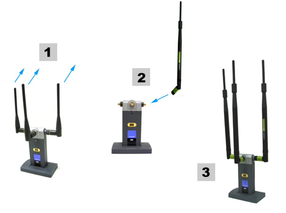
Figure 4-5: Attaching the Antenna Cables 7
Figure 4-6: Available Wireless Network Screen 8
Figure 4-7: Available Wireless Network Screen 9
Figure 4-8: WEP Key Needed for Connection 9
Figure 4-9: WPA-Personal Needed for Connection 10
Figure 4-10: WPA2-Personal Needed for Connection 10
Figure 4-11: Congratulations Screen 10
Figure 4-12: Available Wireless Network Screen 11
Figure 4-13: Network Settings Screen 11
Figure 4-14: Wireless Mode Screen 12
Figure 4-15: Ad-Hoc Mode Settings Screen 12
Figure 4-16: Wireless Security Screen 13
Figure 4-17: Wireless Security - WEP Screen 13
Figure 4-18: Wireless Security - WPA Personal Screen 14
Figure 4-19: Wireless Security - WPA2 Personal Screen 14
Figure 4-20: Wireless Security - WPA Enterprise Using EAP-TLS Screen 15
Figure 4-21: Wireless Security - WPA Enterprise Using PEAP Screen 15
Figure 4-22: Wireless Security - RADIUS Screen 16
Figure 4-23: Confirm New Settings Screen 17
Figure 4-24: Congratulations Screen 17
Figure 5-1: Wireless Network Monitor Icon 18
Figure 5-2: Link Information Screen 18
Figure 5-3: More Information - Wireless Network Status Screen 19
Figure 5-4: More Information - Wireless Network Statistics Screen 20
Figure 5-5: Site Survey Screen 21
Figure 5-6: WEP Key Needed for Connection 21
Figure 5-7: WPA-Personal Needed for Connection 22

Wireless-G PCI Adapter with SRX
Figure 5-8: WPA2-Personal Needed for Connection 22
Figure 5-9: Profiles Screen 23
Figure 5-10: Import a Profile 23
Figure 5-11: Export a Profile 23
Figure 5-12: Create a New Profile 24
Figure 5-13: Available Wireless Network Screen 24
Figure 5-14: Available Wireless Network Screen 25
Figure 5-15: WEP Key Needed for Connection 25
Figure 5-16: WPA-Personal Needed for Connection 26
Figure 5-17: WPA2-Personal Needed for Connection 26
Figure 5-18: Congratulations Screen 26
Figure 5-19: Available Wireless Network Screen 27
Figure 5-20: Network Settings Screen 27
Figure 5-21: Wireless Mode Screen 28
Figure 5-22: Ad-Hoc Mode Settings 28
Figure 5-23: Ad-Hoc Mode Settings Screen 28
Figure 5-24: Wireless Security Screen 29
Figure 5-25: Wireless Security - WEP Screen 29
Figure 5-26: Wireless Security - WPA Personal Screen 30
Figure 5-27: Wireless Security - WPA2 Personal Screen 30
Figure 5-28: Wireless Security - WPA Enterprise Using EAP-TLS Screen 31
Figure 5-29: Wireless Security - WPA Enterprise Using PEAP Screen 31
Figure 5-30: Wireless Security - RADIUS Screen 32
Figure 5-31: Confirm New Settings Screen 33
Figure 5-32: Congratulations Screen 33
Figure B-1: Wireless Network Monitor Icon 38
Figure B-2: Windows XP - Use Windows XP Wireless Configuration 38
Figure B-3: Windows XP Wireless Configuration Icon 38
Figure B-4: Available Wireless Network 39
Figure B-5: No Wireless Security 39
Figure B-6: Network Connection - Wireless Security 40
Figure B-7: Wireless Network Connection 40
Chapter 1: Introduction
Welcome
Thank you for choosing the Wireless-G PCI Adapter with SRX. With this Adapter, your wireless networking
experience will be faster and easier than ever.
How does the Adapter do this? Like all wireless products, the Adapter allows for greater range and mobility
within your wireless network, whether it’s using the Wireless-G (802.11g) or Wireless-B (802.11b) standard.
But what does all of this mean?
Networks are useful tools for sharing computer resources. You can access one printer from different computers
and access data located on another computer's hard drive. Networks are even used for playing multiplayer video
games. So, networks are not only useful in homes and offices, they can also be fun.
PCs equipped with wireless cards and adapters can communicate without cumbersome cables. By sharing the
same wireless settings, within their transmission radius, they form a wireless network.
The included Setup Wizard walks you through configuring the Adapter to your wireless network settings, step by
step. Use the instructions in this Guide to help you set up and connect the Adapter using the Setup Wizard. These
instructions should be all you need to get the most out of the Adapter.
What’s in This User Guide?
This user guide covers the steps for setting up and using the Wireless-G PCI Adapter with SRX.
• Chapter 1: Introduction
This chapter describes the Adapter’s applications and this User Guide.
• Chapter 2: Planning Your Wireless Network
This chapter discusses a few of the basics about wireless networking.
• Chapter 3: Getting to Know the Wireless-G PCI Adapter with SRX
This chapter describes the physical features of the Adapter.
• Chapter 4: Setting Up and Connecting the Wireless-G PCI Adapter with SRX
This chapter shows you how to set up and connect the Adapter.
802.11b: an IEEE wireless networking
standard that specifies a maximum data
transfer rate of 11Mbps and an operating
frequency of 2.4GHz.
adapter: a device that adds network
functionality to your PC.
network: a series of computers or devices
connected for the purpose of data sharing,
storage, and/or transmission between
users.
802.11g: an IEEE wireless networking
standard that specifies a maximum data
transfer rate of 54Mbps and an operating
frequ
ency of 2 4GHz
MIMO
The Wireless-G PCI Adapter with SRX
combines smart antenna technology with
standards-based Wireless-G (802.11g)
networking. By overlaying the signals of two
Wireless-G compatible radios, the "Multiple
In, Multiple Out" (MIMO) technology
effectively achieve greater throughput.
Unlike ordinary wireless networking
technologies that are confused by signal
reflections, MIMO actually uses these
reflections to increase the range and reduce
"dead spots" in the wireless coverage area.
Wireless-G PCI Adapter with SRX
Chapter 1: Introduction 1
Welcome

2
Chapter 1: Introduction
What’s in This User Guide?
Wireless-G PCI Adapter with SRX
• Chapter 5: Using the Wireless Network Monitor
This chapter explains how to use the Adapter’s Wireless Network Monitor.
• Appendix A: Troubleshooting
This appendix describes some problems and solutions, as well as frequently asked questions, regarding
installation and use of the Adapter.
• Appendix B: Using Windows XP Wireless Zero Configuration
This chapter instructs you on how to use Window XP Wireless Zero Configuration.
• Appendix C: Wireless Security
This appendix discusses security issues regarding wireless networking and measures you can take to help
protect your wireless network.
• Appendix D: Windows Help
This appendix describes how you can use Windows Help for instructions about networking, such as installing
the TCP/IP protocol.
• Appendix E: Glossary
This appendix gives a brief glossary of terms frequently used in networking.
• Appendix F: Specifications
This appendix provides the Adapter’s technical specifications.
• Appendix G: Warranty Information
This appendix supplies the Adapter’s warranty information.
• Appendix H: Regulatory Information
This appendix supplies the Adapter’s regulatory information.
• Appendix I: Contact Information
This appendix provides contact information for a variety of Linksys resources, including Technical Support.

3
Chapter 2: Planning Your Wireless Network
Network Topology
Wireless-G PCI Adapter with SRX
Chapter 2: Planning Your Wireless Network
Network Topology
A wireless network is a group of computers, each equipped with one wireless adapter. Computers in a wireless
network must be configured to share the same radio channel. Several PCs equipped with wireless cards or
adapters can communicate with one another to form an ad-hoc network.
Linksys wireless adapters also provide users access to a wired network when using an access point or wireless
router. An integrated wireless and wired network is called an infrastructure network. Each wireless PC in an
infrastructure network can talk to any computer in a wired network infrastructure via the access point or wireless
router.
An infrastructure configuration extends the accessibility of a wireless PC to a wired network, and can double the
effective wireless transmission range for two wireless adapter PCs. Since an access point is able to forward data
within a network, the effective transmission range in an infrastructure network can be doubled.
Roaming
Infrastructure mode also supports roaming capabilities for mobile users. Roaming means that you can move your
wireless PC within your network and the access points will pick up the wireless PC's signal, providing that they
both share the same channel and SSID.
Before you consider enabling roaming, choose a feasible radio channel and optimum access point position.
Proper access point positioning combined with a clear radio signal will greatly enhance performance.
infrastructure: a wireless network that is
bridged to a wired network via an access point.
ad-hoc: a group of wireless devices
communicating directly with each other (peer-
to-peer) without the use of an access point.
roaming: the ability to take a wireless device
from one access point's range to another without
losing the connection.
ssid: your wireless network's name.
topology: the physical layout of a network.
access point: a device that allows wireless-
equipped computers and other devices to
communicate with a wired network. Also used to
expand the range of a wireless network

4
Chapter 2: Planning Your Wireless Network
Network Layout
Wireless-G PCI Adapter with SRX
Network Layout
Linksys wireless access points and wireless routers have been designed for use with 802.11b and 802.11g
products. Products using the 802.11g and 802.11b standards can communicate with each other.
Access points and wireless routers are compatible with 802.11b and 802.11g adapters, such as the notebook
adapters for your laptop computers, PCI adapters for your desktop PCs, and USB adapters for when you want to
enjoy USB connectivity. Wireless products will also communicate with a wireless print server.
When you wish to connect your wired network with your wireless network, network ports on access points and
wireless routers can be connected to any of Linksys's switches or routers.
With these, and many other, Linksys products, your networking options are limitless. Go to the Linksys website at
www.linksys.com for more information about wireless products. router: a networking device that connects multiple
networks together
switch: a data switch that connects computing devices
to host computers, allowing a large number of devices
to share a limited number of ports

5
Chapter 3: Getting to Know the Wireless-G Notebook Adapter with SRX
Overview
Wireless-G PCI Adapter with SRX
Chapter 3: Getting to Know the Wireless-G Notebook Adapter
with SRX
Overview
The Adapter has two parts, the antenna stand and PCI card.
The LED Indicator
The Adapter's LED on the Adapter’s antenna stand displays information about the wireless connection.
(Activity) Green. The LED lights up when the Adapter has an active wireless connection. It flashes when the
Adapter is transmitting or receiving data.
The Cable Connectors
The Adapter's connectors attach the antenna stand’s cables to the PCI card part of the Adapter.
ANT. The ANT. connectors are connection points for the stand’s antenna cables.
ACT. The ACT. connector is a connection point for the stand’s activity cable, which activates the LED on
the antenna stand.
Figure 3-1: Adapter’s LED
Figure 3-2: Adapter’s Connectors