LINKSYS HGA7T-4 Wireless Network Access Point User Manual WAP11 V2 8 UG Rev NC
LINKSYS LLC Wireless Network Access Point WAP11 V2 8 UG Rev NC
UserManual.wiki
>
LINKSYS
>
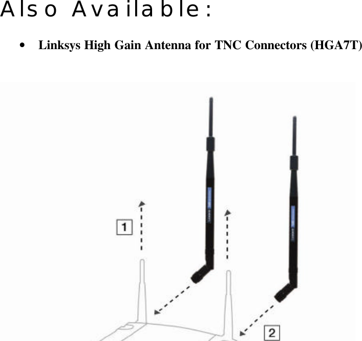
HGA7T 4 User Manual
user manual
Navigation menu
Upload a User Manual
Namespaces
Wiki Guide
HTML
PDF
Info
Views
User Manual
Discussion / Help
Navigation