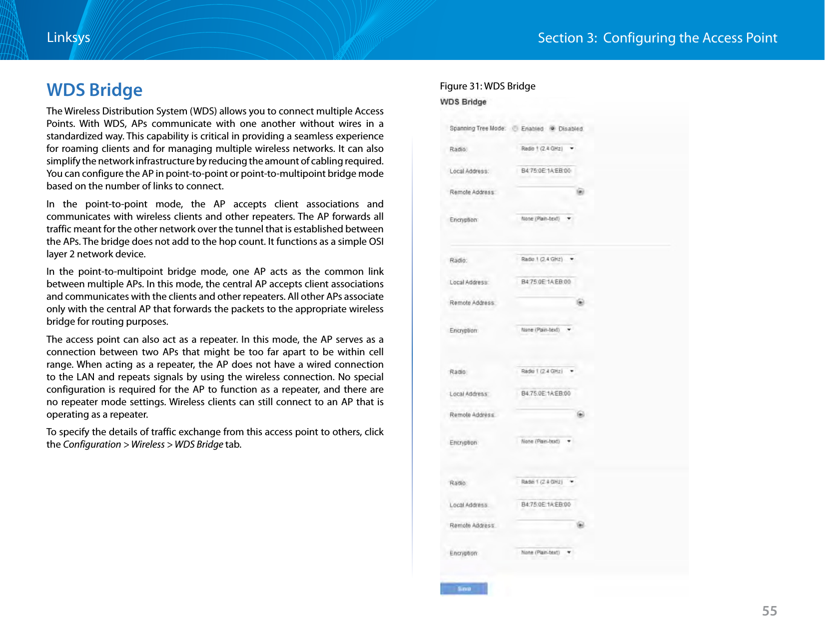
LINKSYS LAPAC1750PO AC1750 Pro Dual Band Access Point User Manual User Guide Linksys LAPAC1750PRO
LINKSYS LLC AC1750 Pro Dual Band Access Point User Guide Linksys LAPAC1750PRO
LINKSYS >
Contents
- 1. User Manual-1
- 2. User Manual-2
User Manual-1

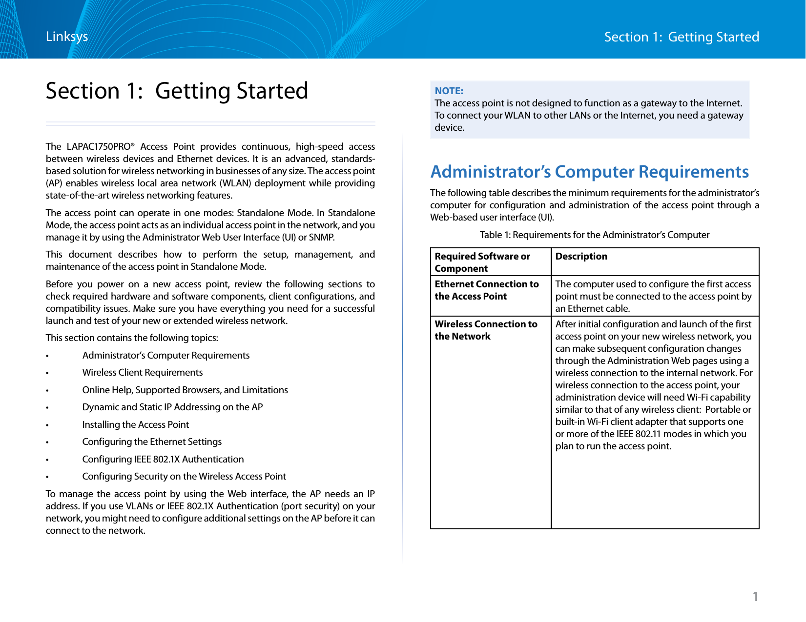
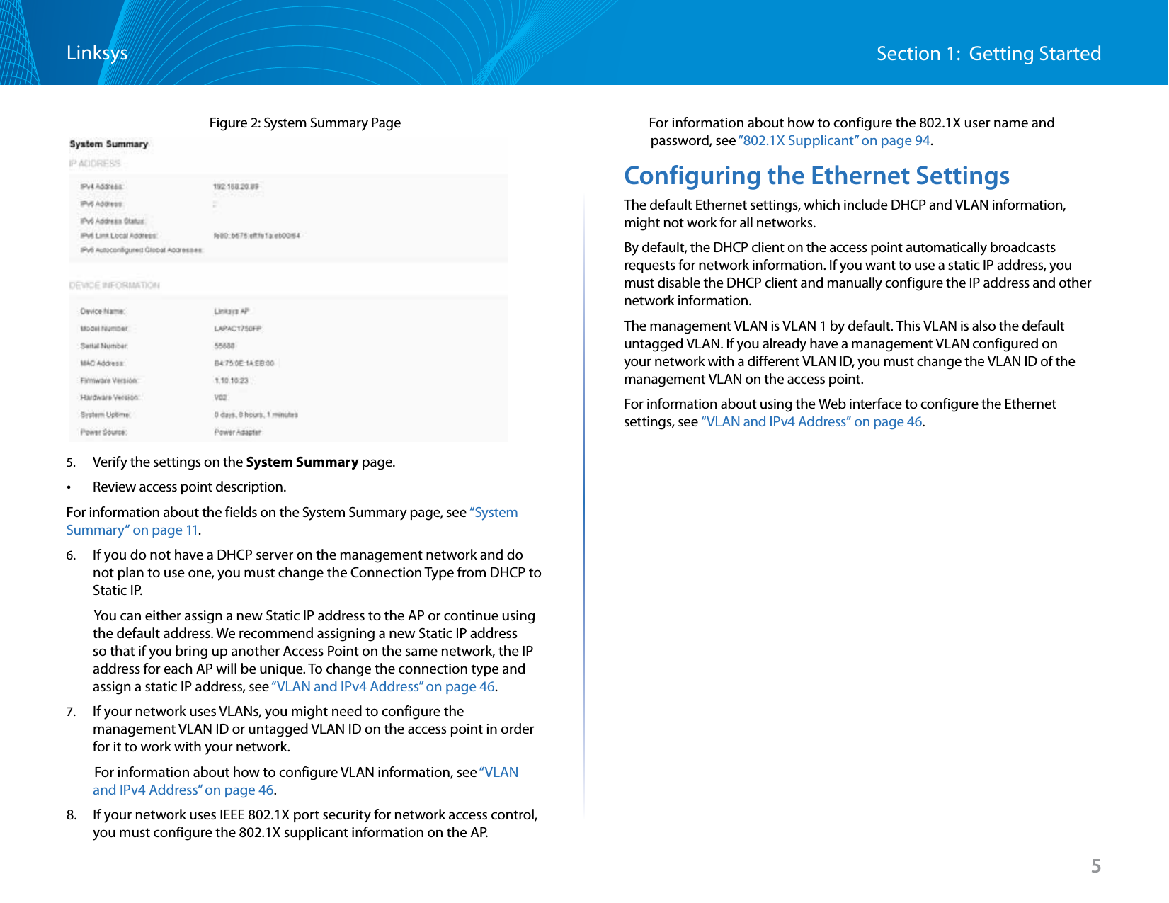
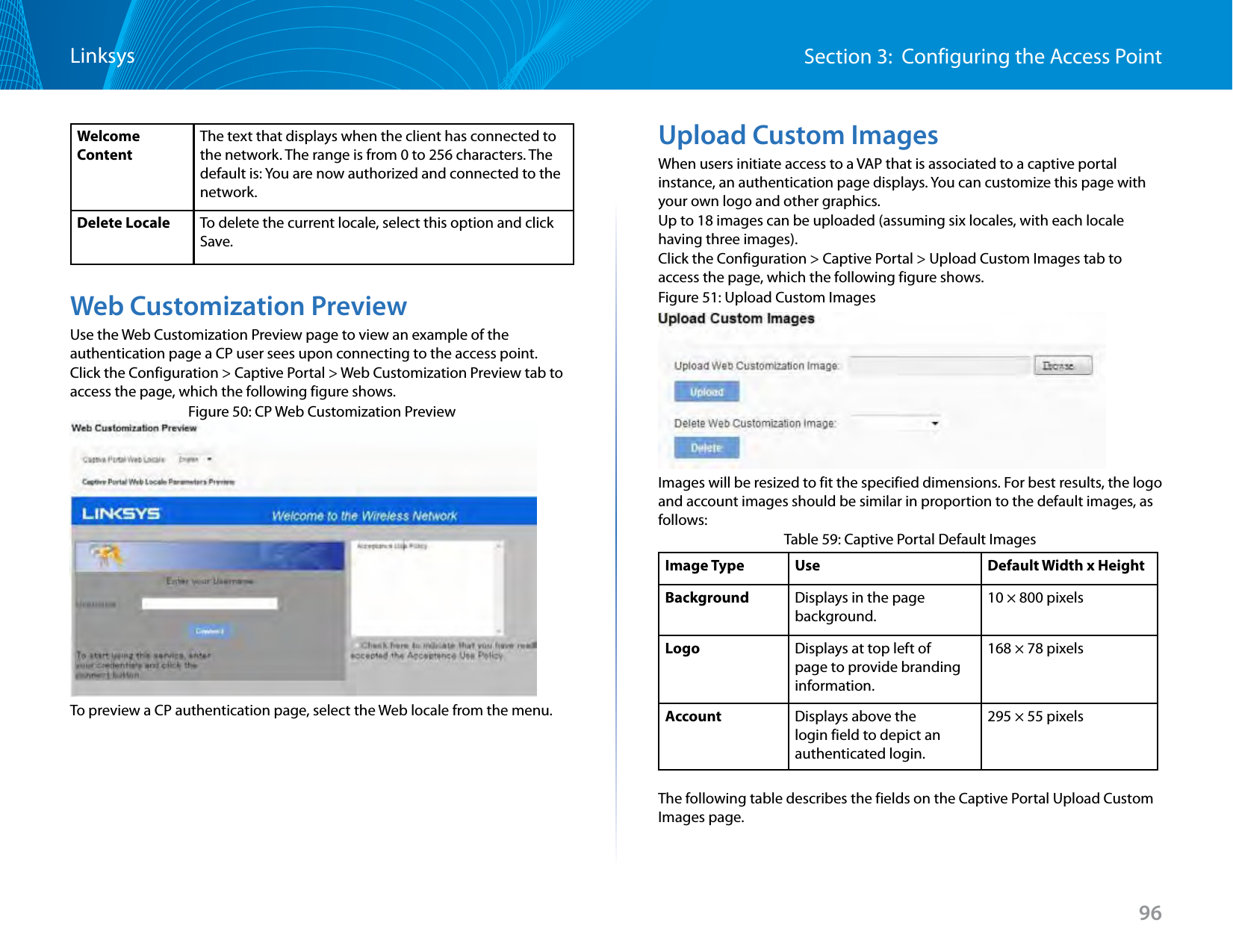
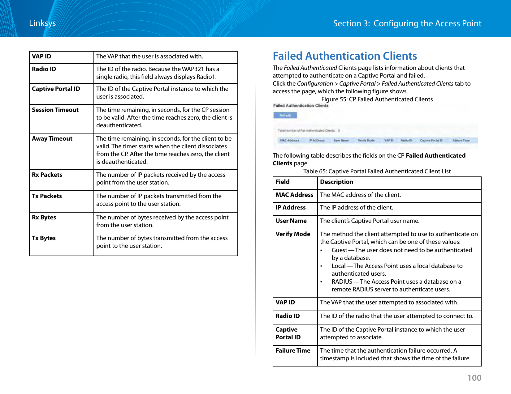
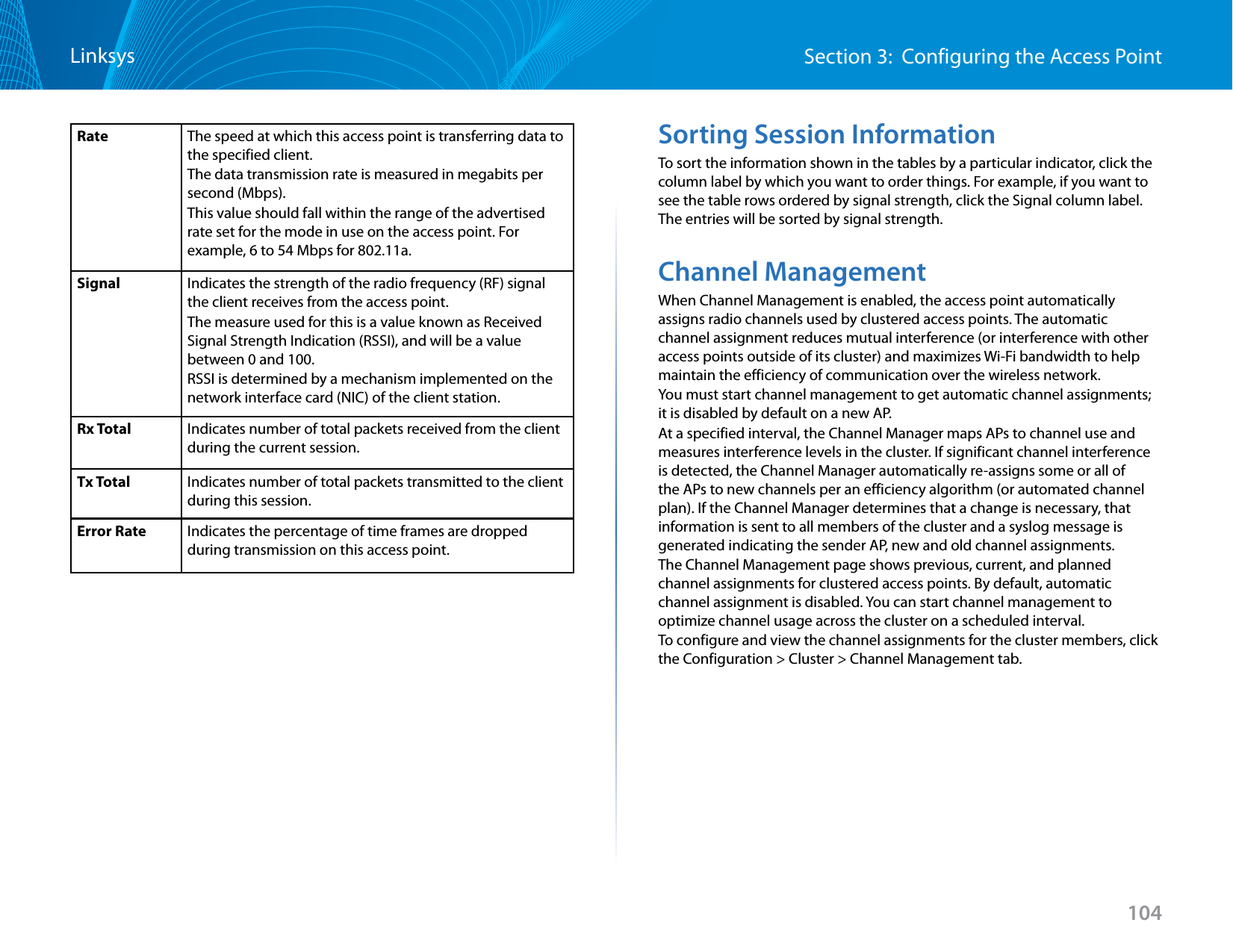
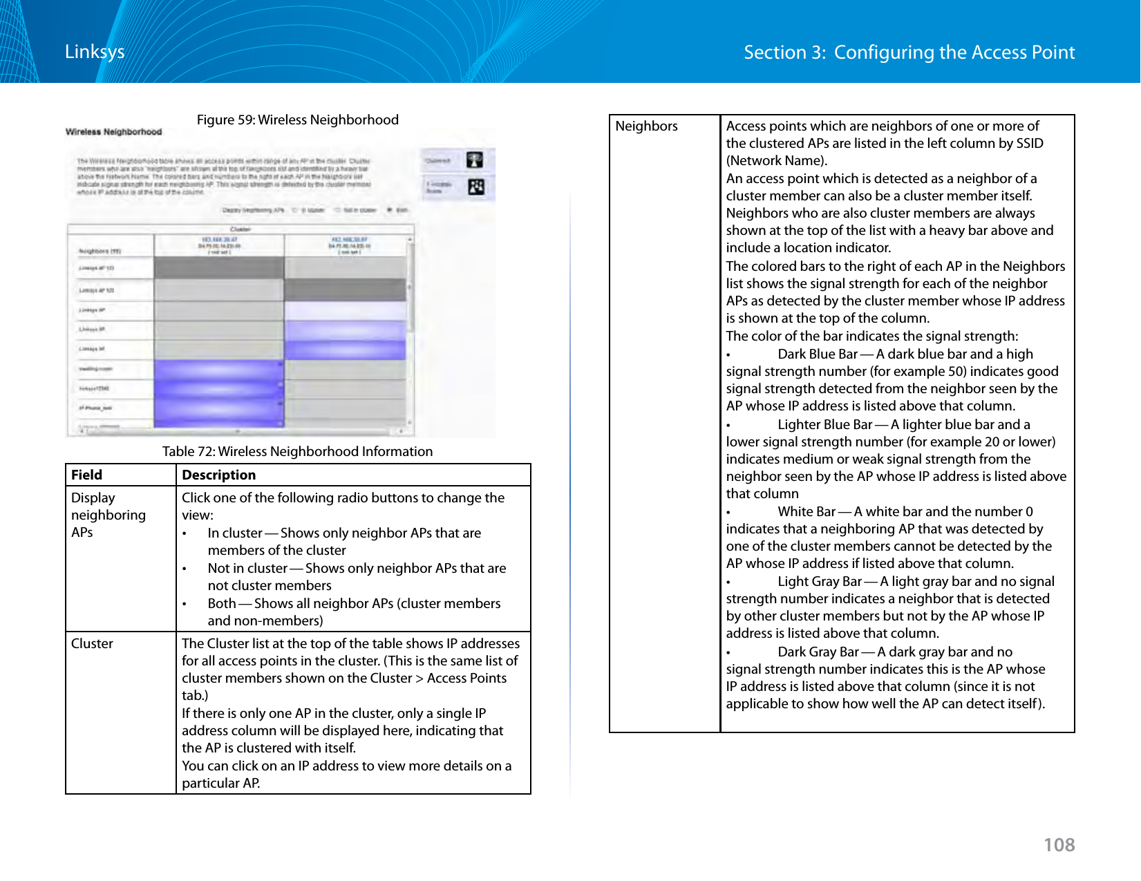
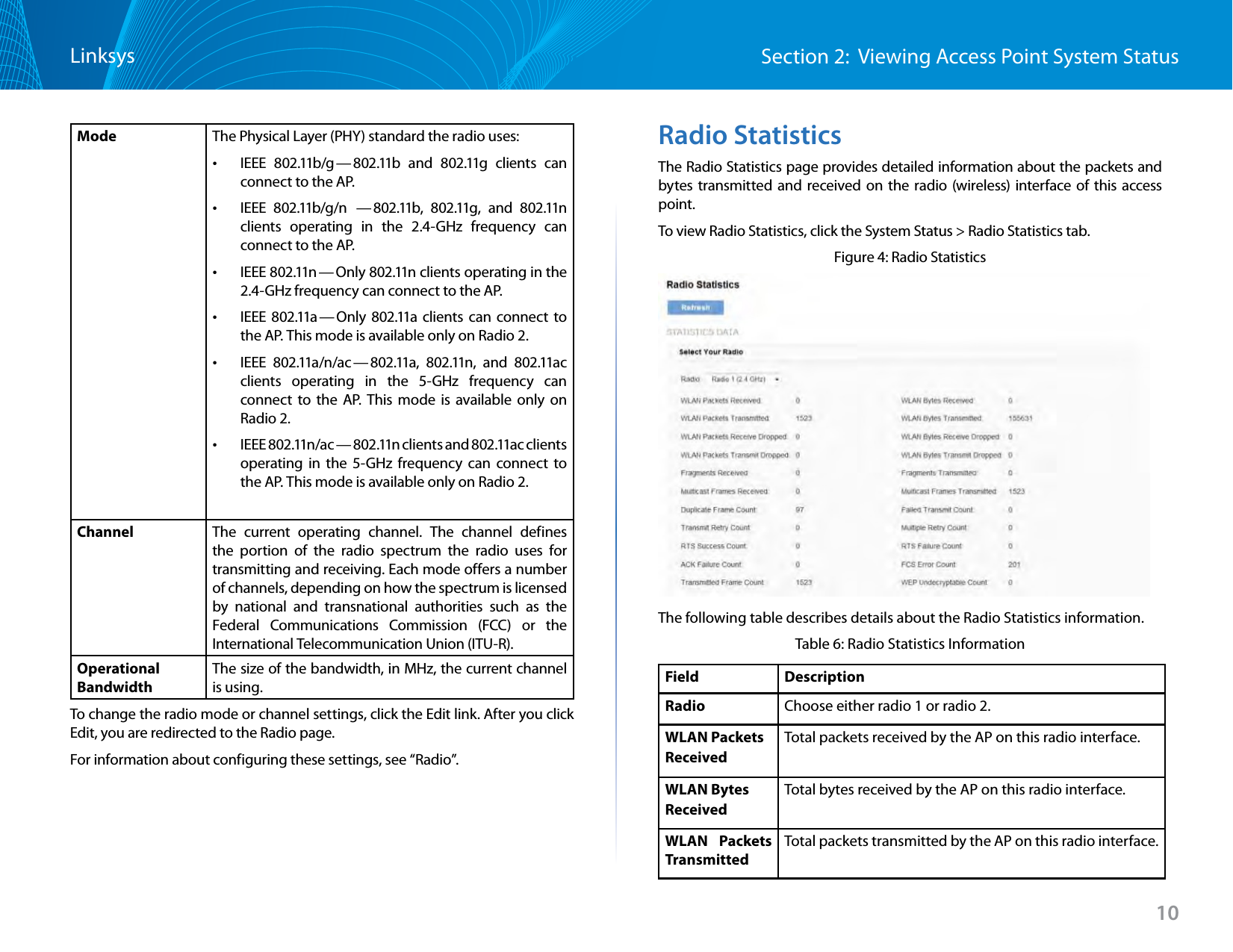
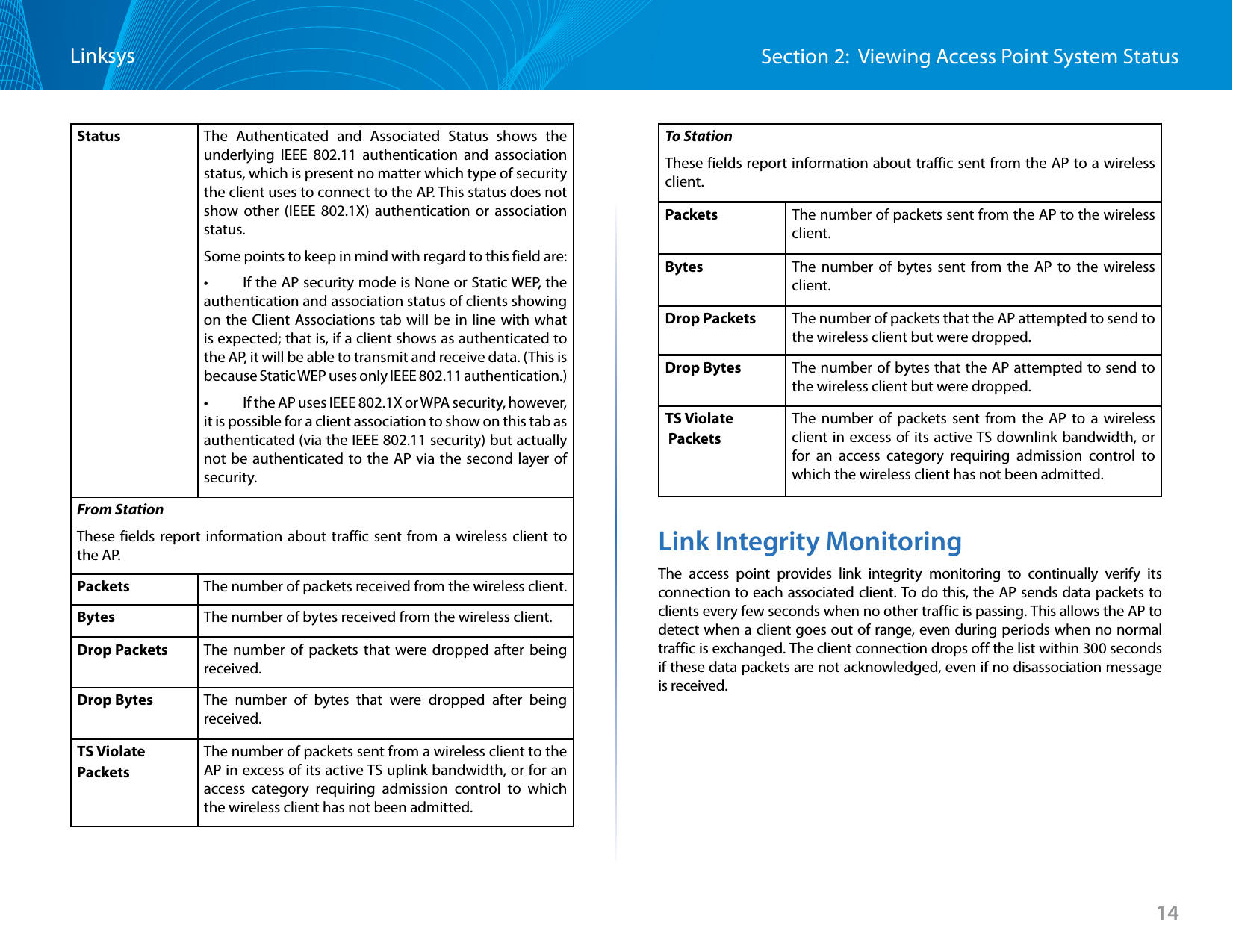
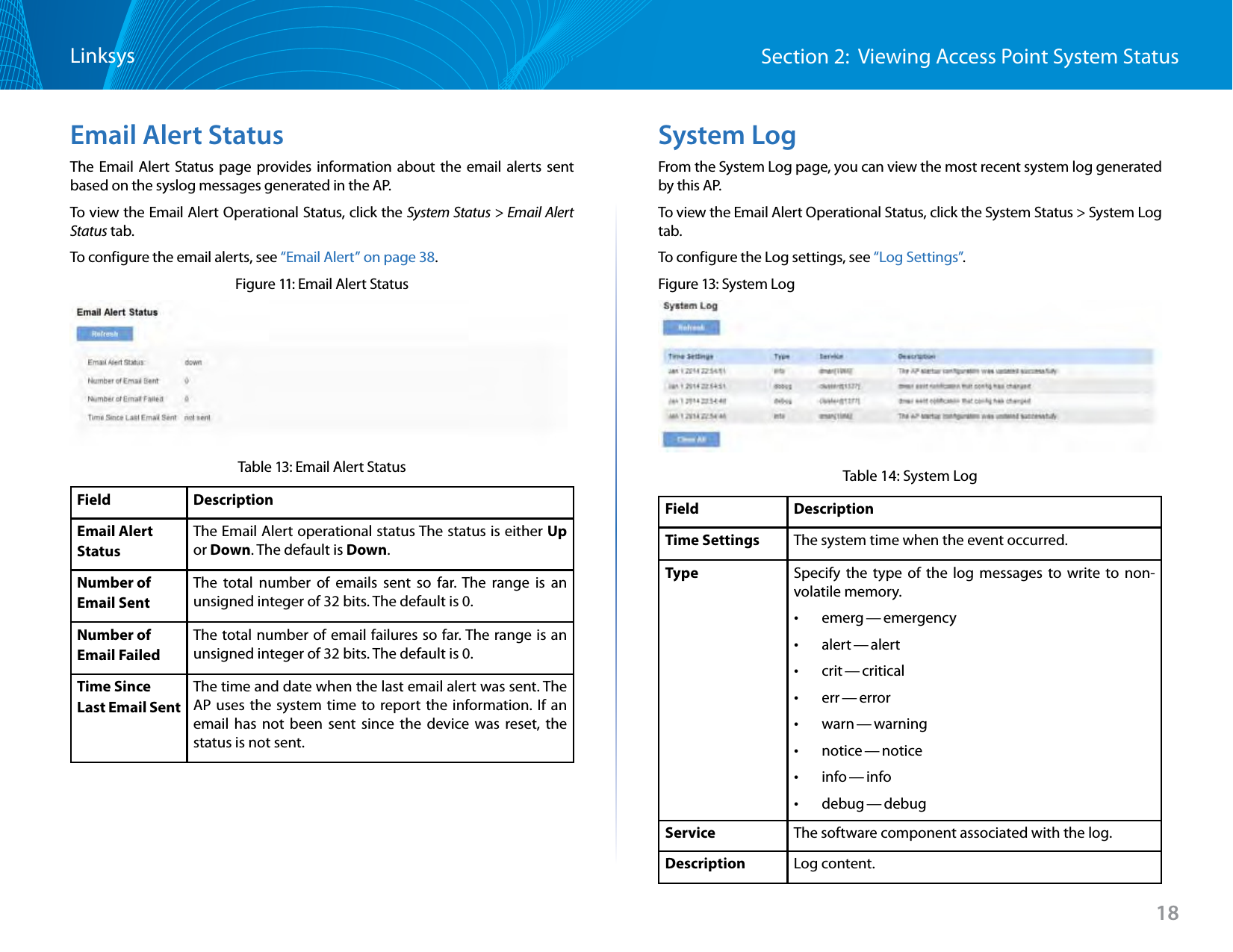
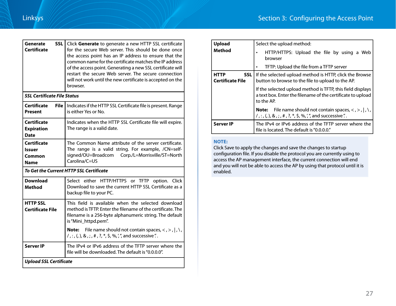
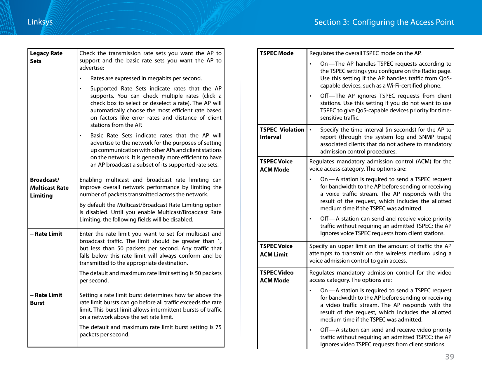
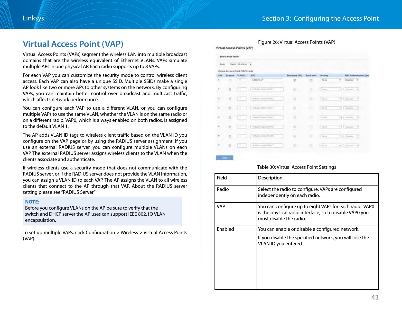
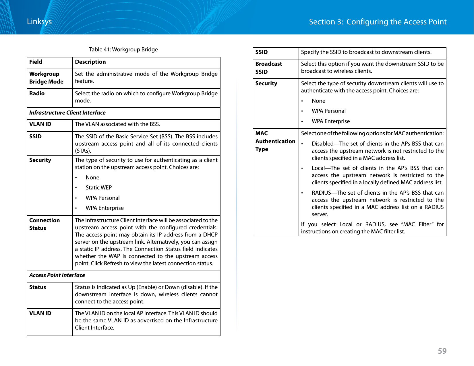
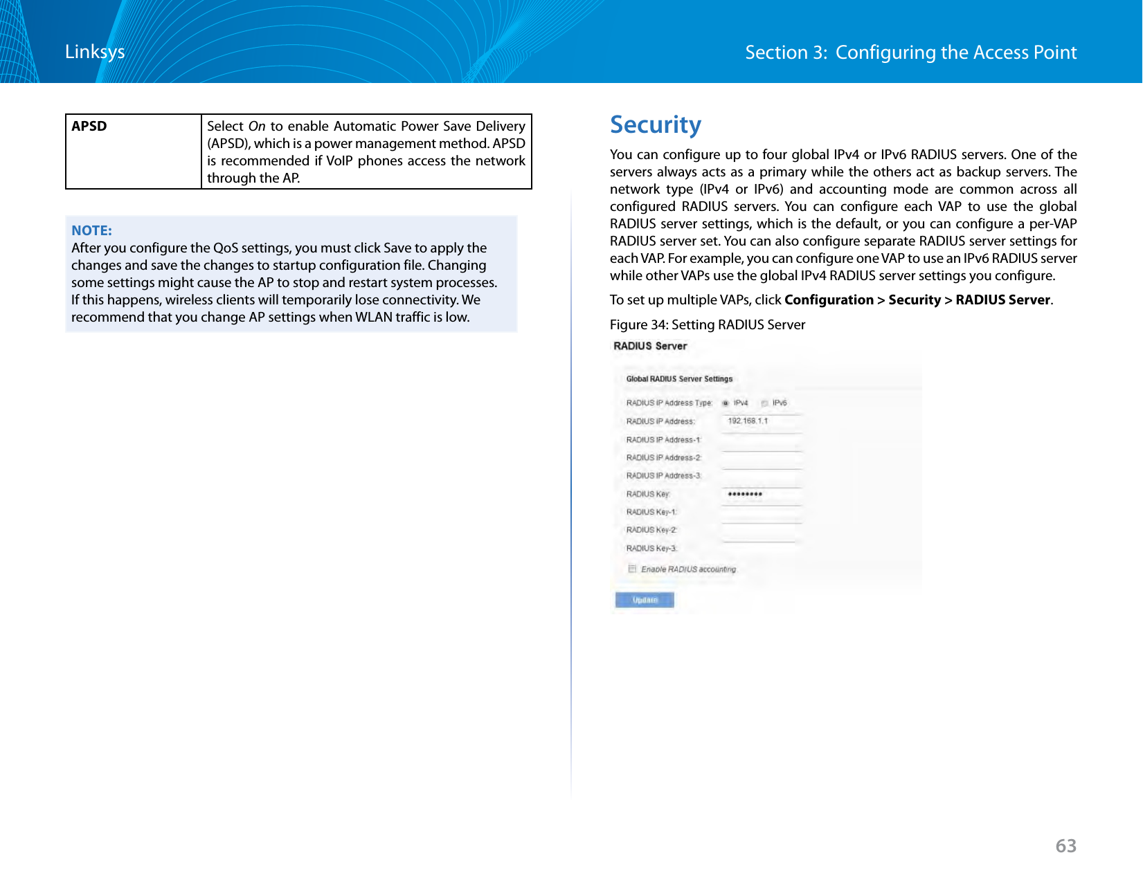
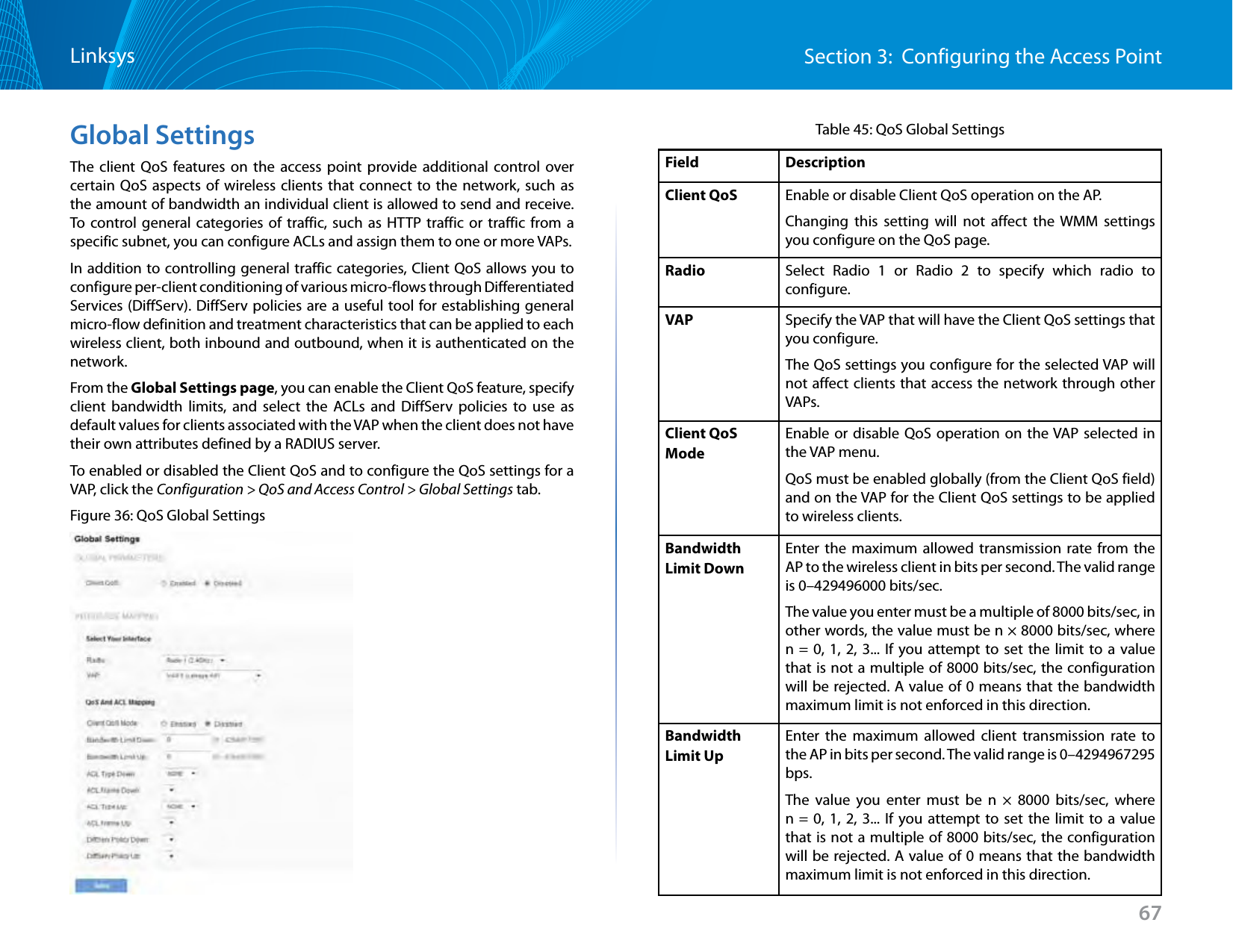
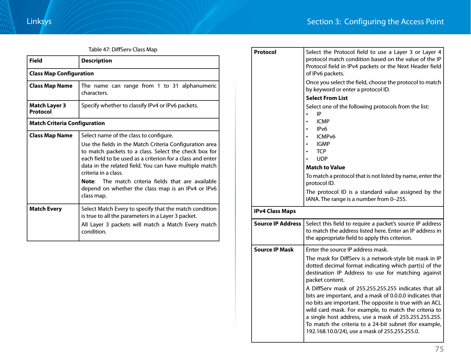
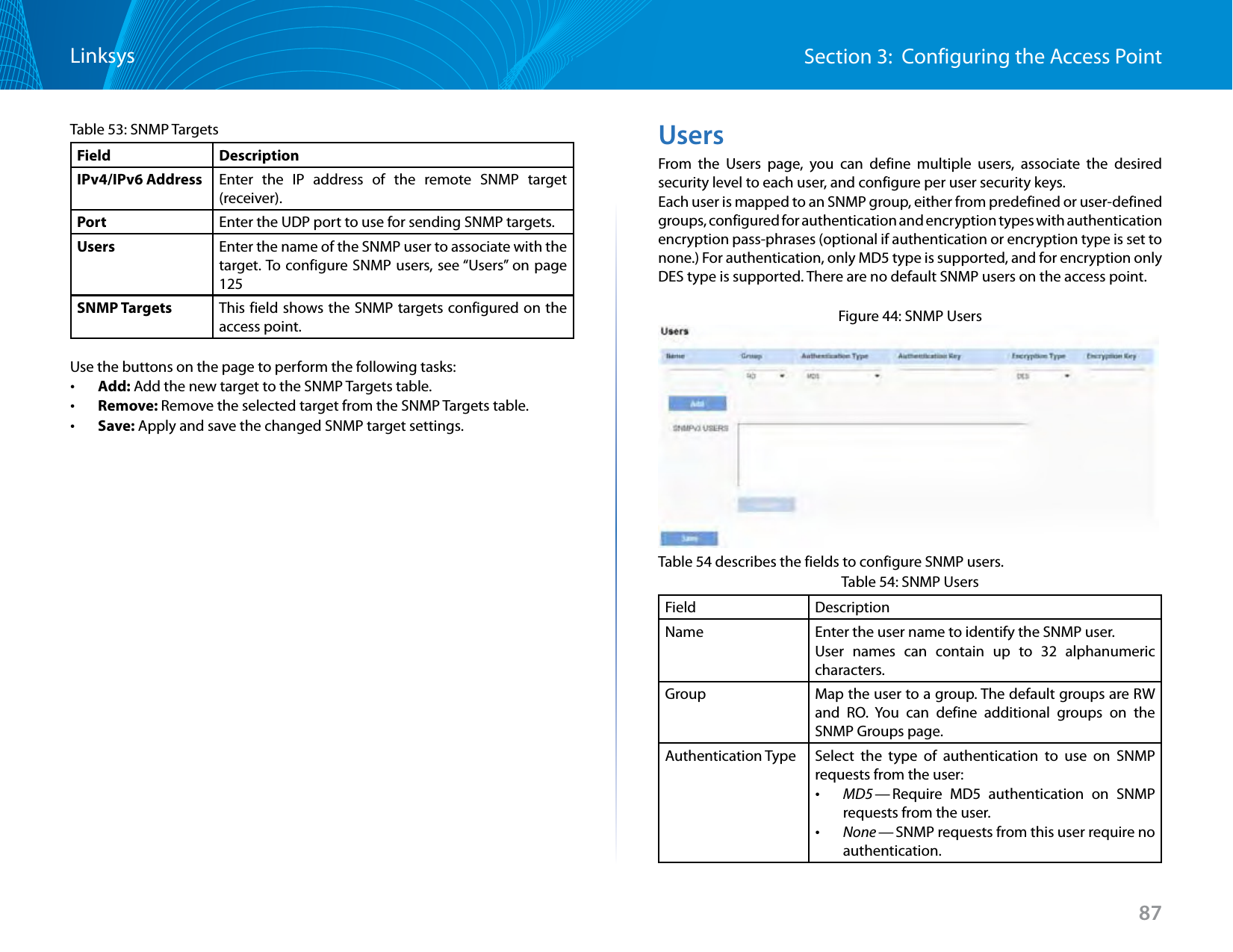
![Section 2: Viewing Access Point System StatusLinksys8MAC Address Shows the MAC address of the AP. The address shown here is the MAC address associated with the management interface. This is the address by which the AP is known externally to other networks.Firmware Version Shows version information about the firmware currently installed on the AP. As new versions of the WLAN AP firmware become available, you can upgrade the firmware on your AP. Hardware Version Identifies the AP hardware version.System Uptime Provides information about the system start up time.Power Source The power source of monitor system is the power adapter or PoE.Connecting to the AP Web Interface Using the IPv6 AddressTo connect to the AP by using the IPv6 global address or IPv6 Link Local address, you must enter the AP address into your browser in a special format.NOTE:The following instructions and examples work with Microsoft Internet Explorer 7 (IE7) and might not work with other browsers.To connect to an IPv6 global address, add square brackets around the IPv6 address. For example, if the AP global IPv6 address is 2520::230:abff:fe00:2420, type the following address into the IE7 address field: http://[2520::230:abff:fe00:2420].To connect to the iPv6 Link Local address, replace the colons (:) with hyphens (-), add the interface number, preceded by an “s,” then add “.ipv6-literal.net.” For example, if the AP Link Local address is fe80::230:abff:fe00:2420, and the Windows interface is defined as “%6,” type the following address into the IE7 address field: http://fe80--230-abff-fe00-2420s6.ipv6-literal.net.Network InterfacesThis page displays the current settings for the wired Ethernet interface and the wireless radio interfaces on the AP.To monitor Ethernet LAN (wired) and wireless LAN (WLAN) settings, click the System Status > Status and Statistics > Network Interfaces tab.Figure 3: Viewing Network InterfacesNOTE:The information on this page is read-only. To change the wired or wireless interface settings, click the Edit link associated with the appropriate section.](https://usermanual.wiki/LINKSYS/LAPAC1750PO.User-Manual-1/User-Guide-2258455-Page-10.png)
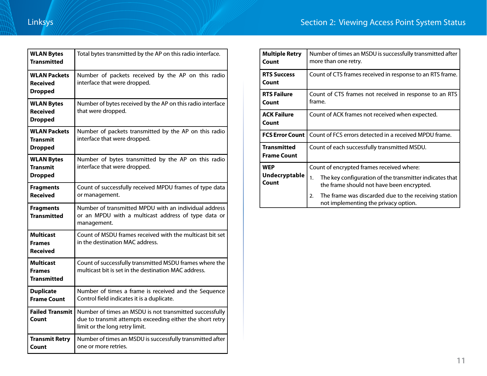
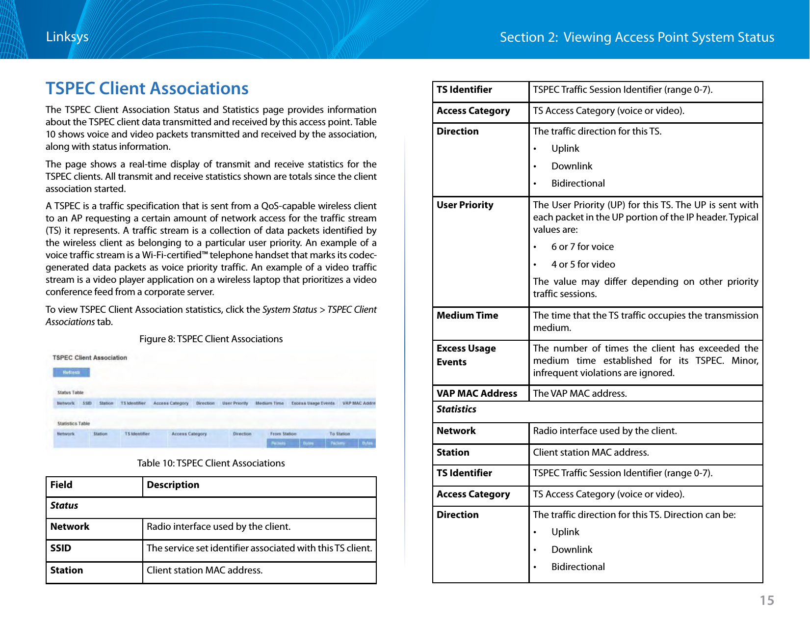
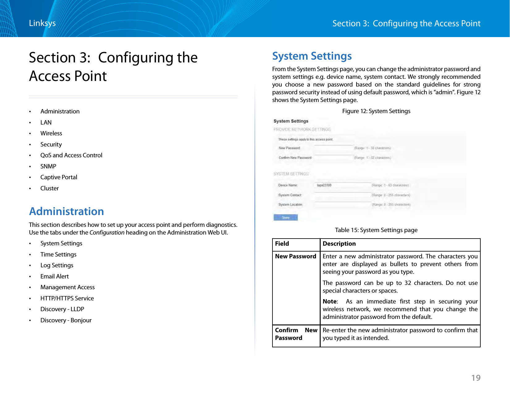
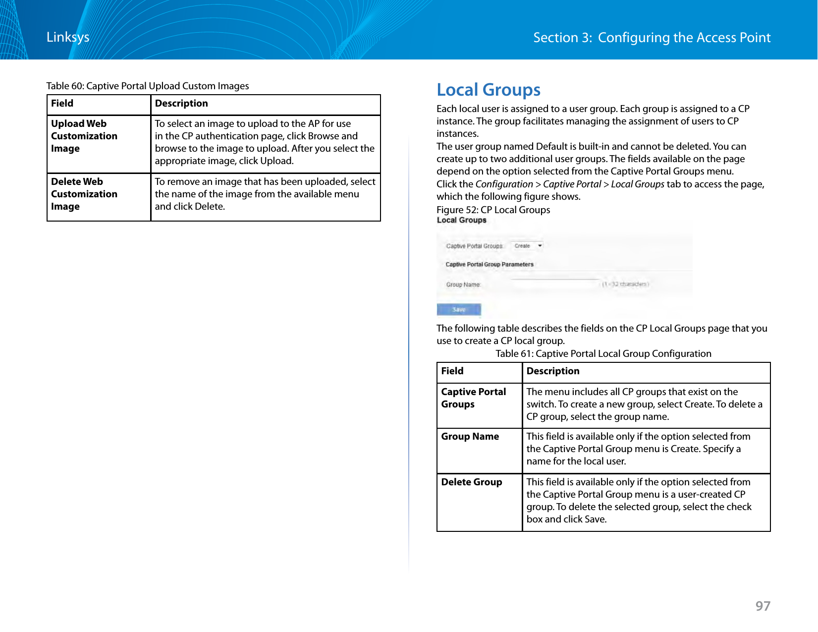
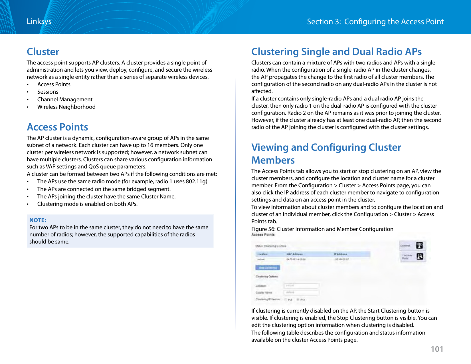
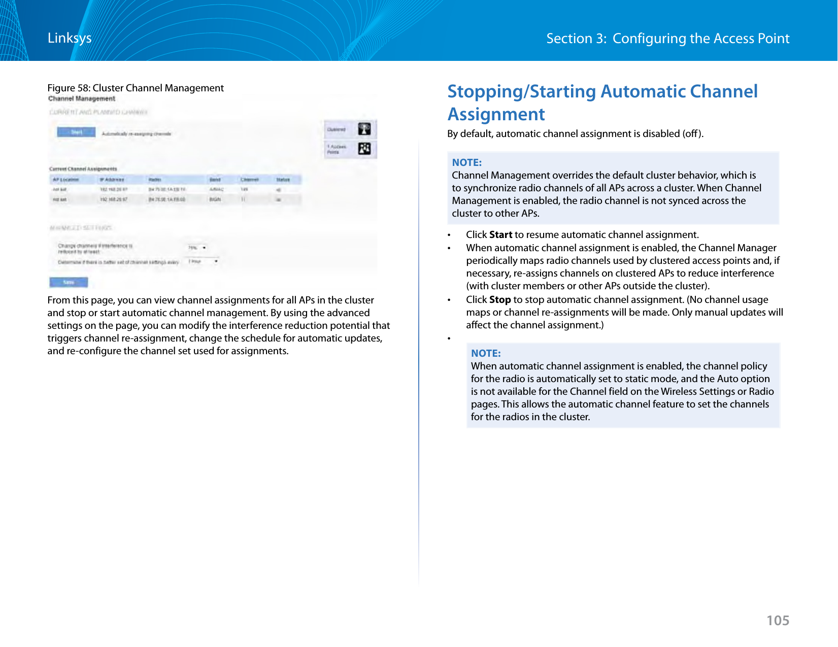
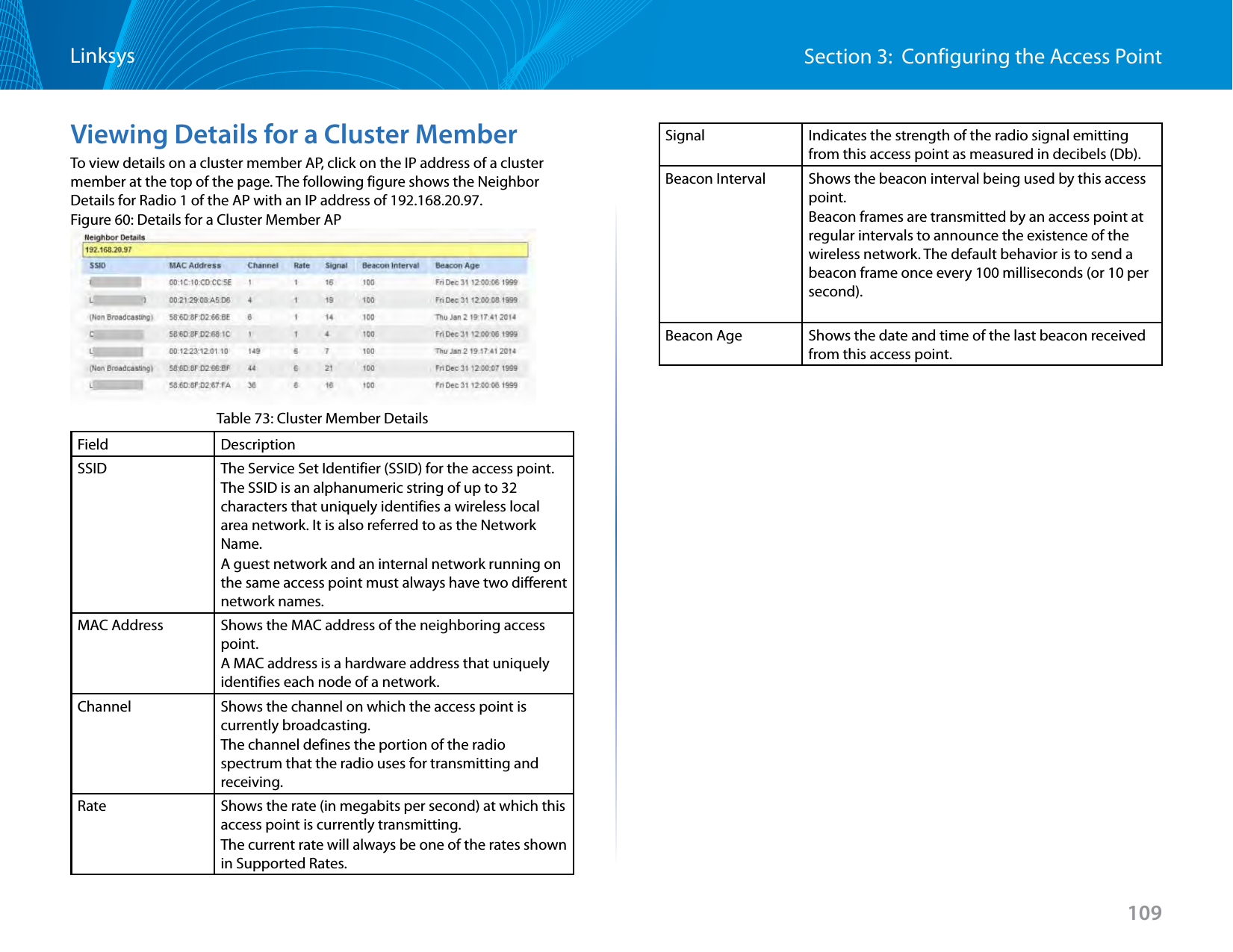
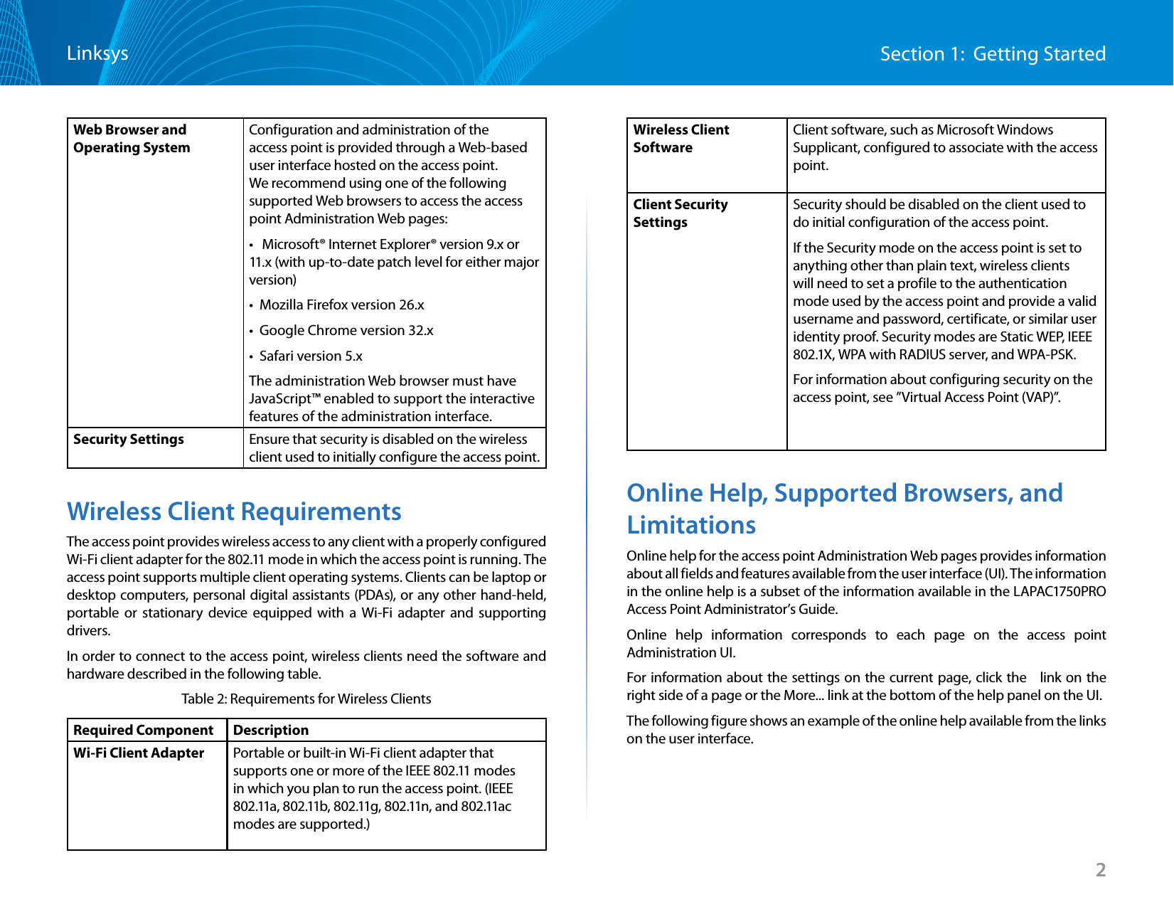
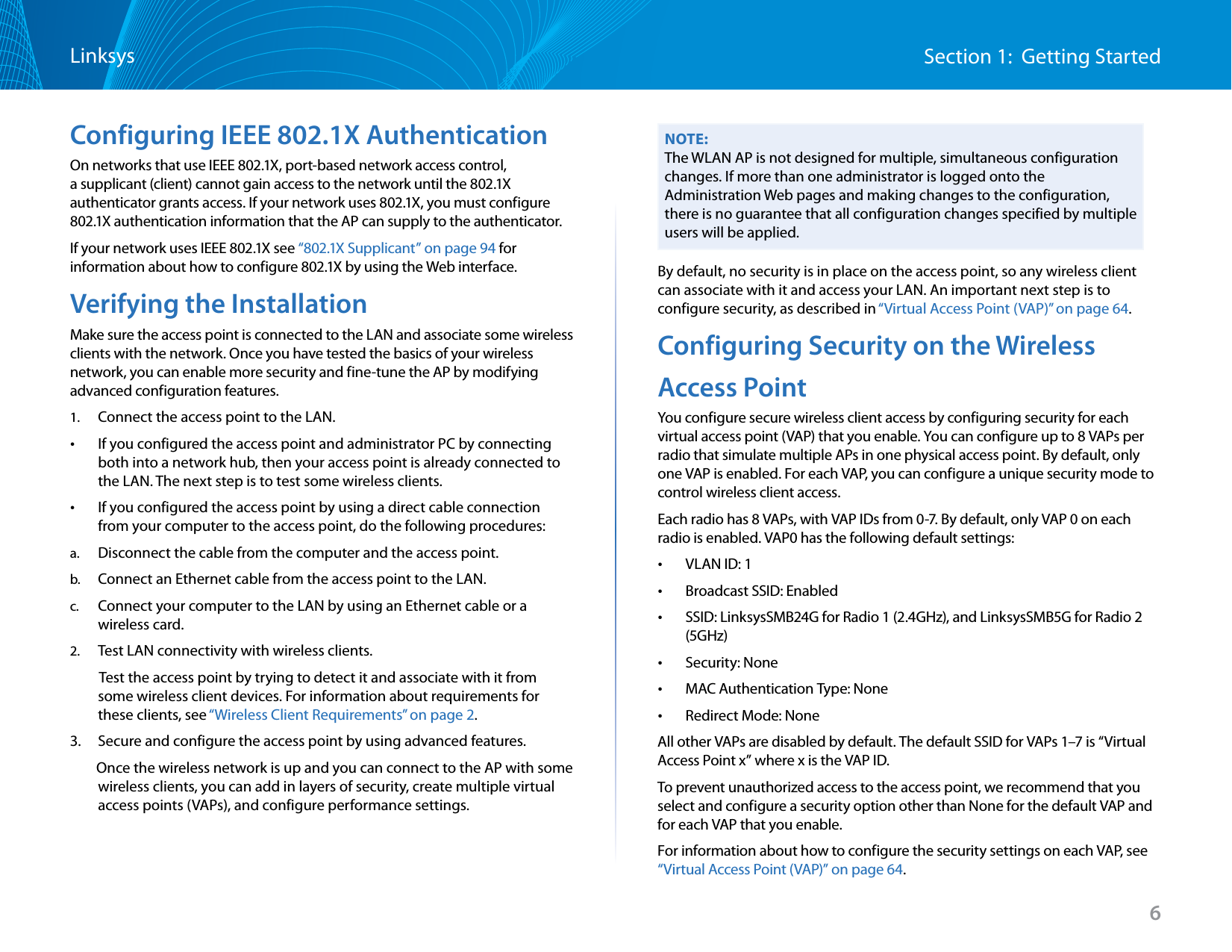
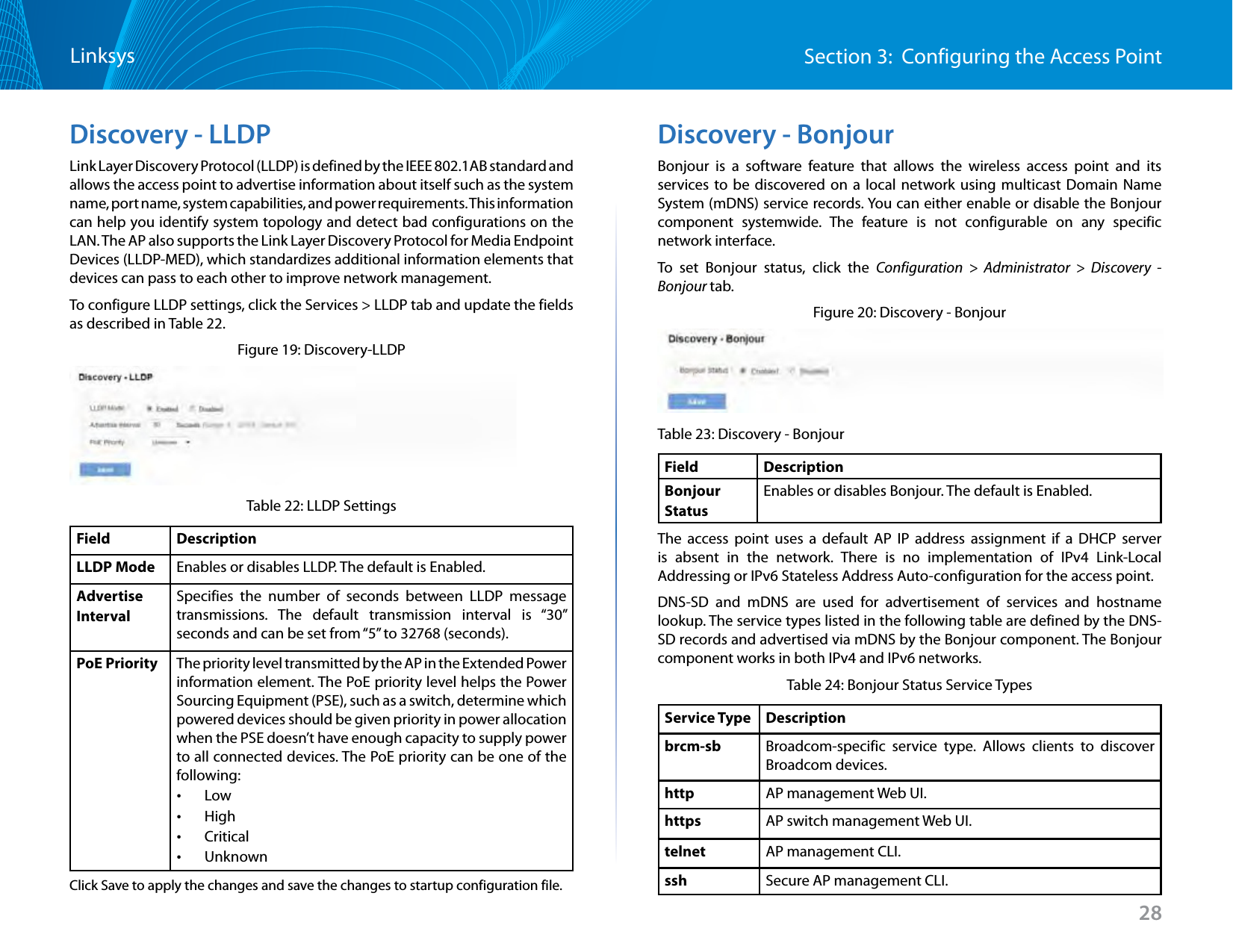
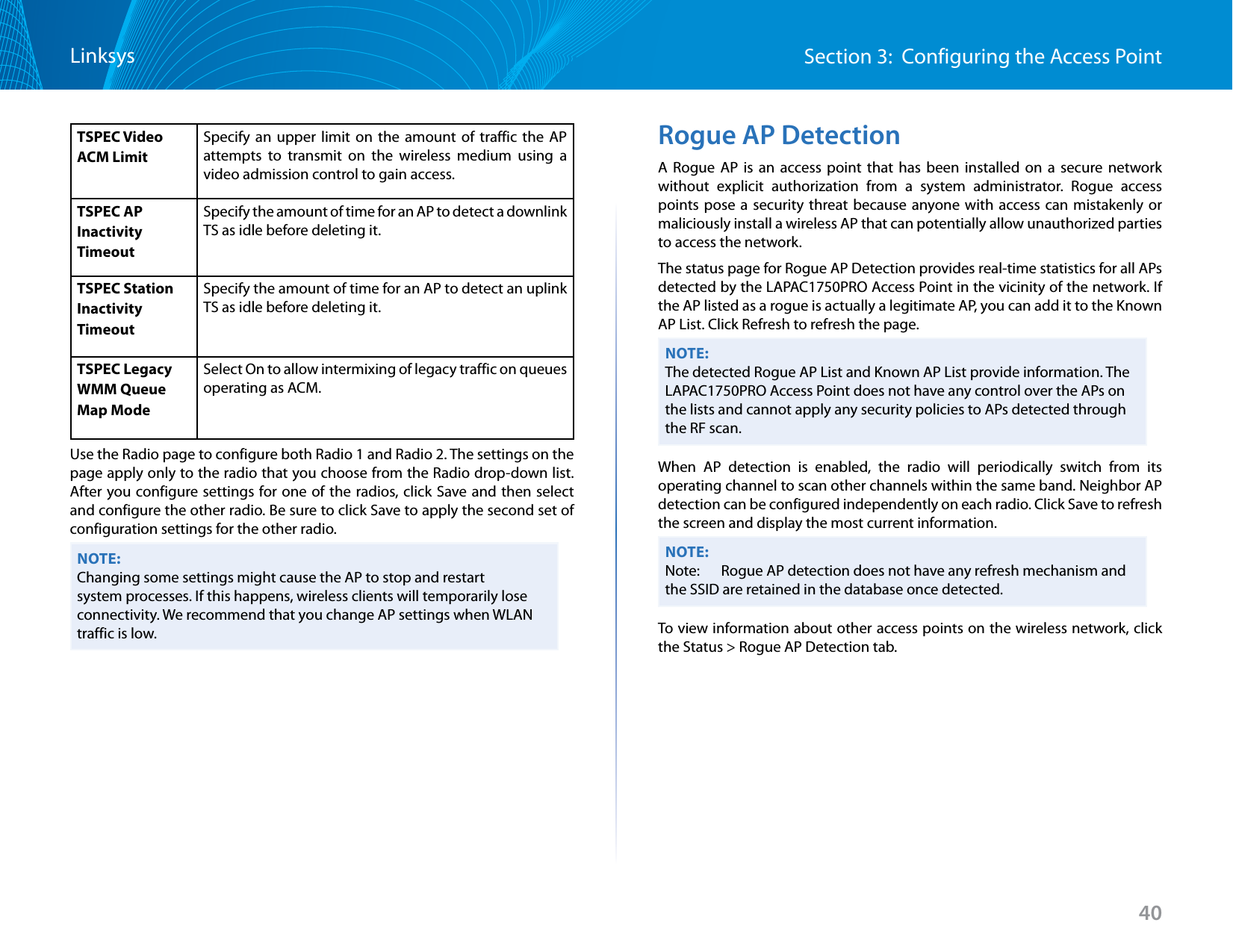
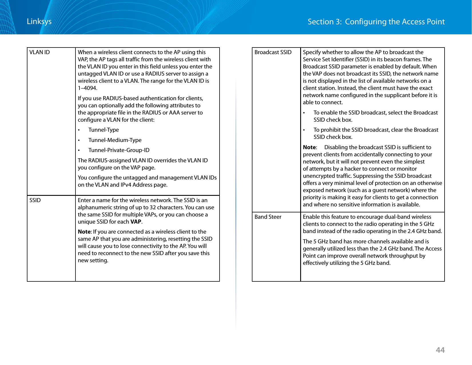
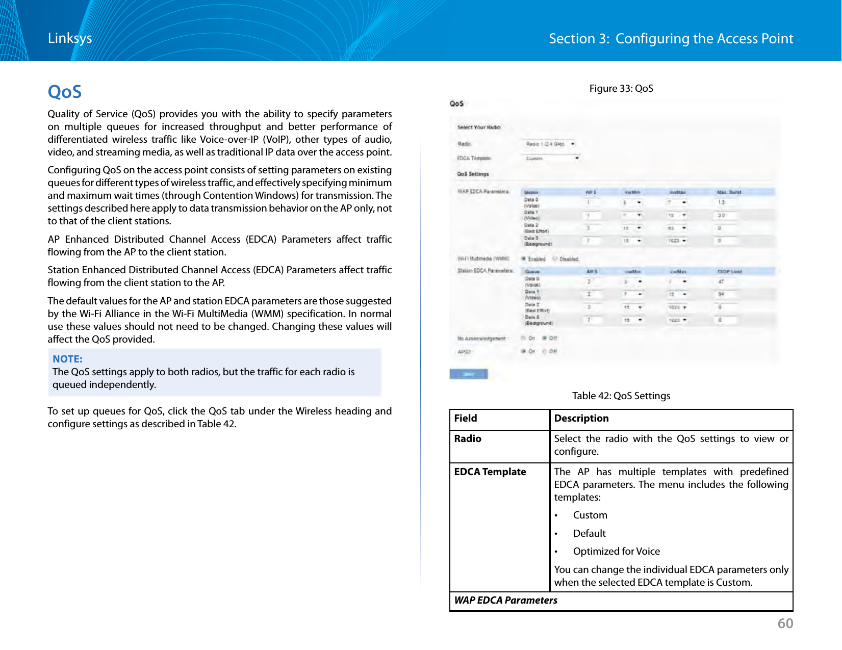
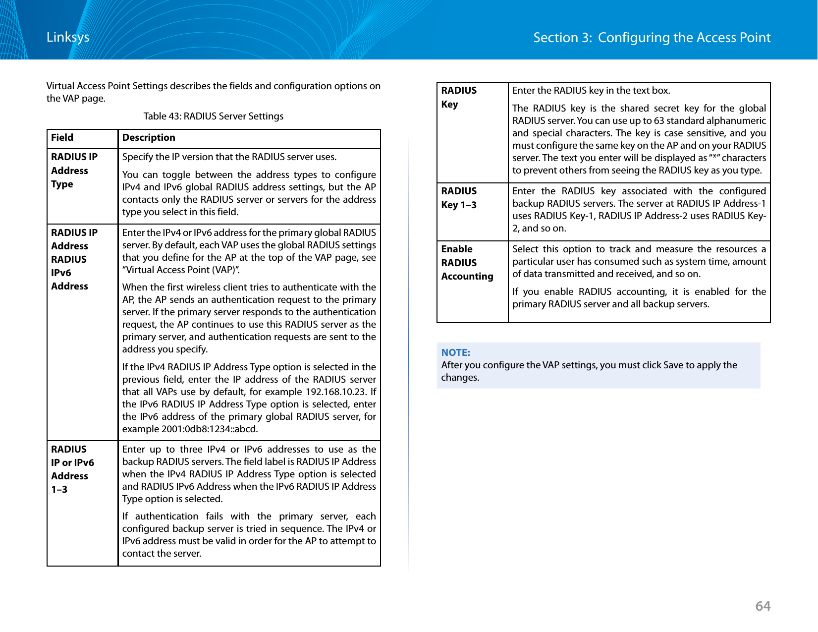
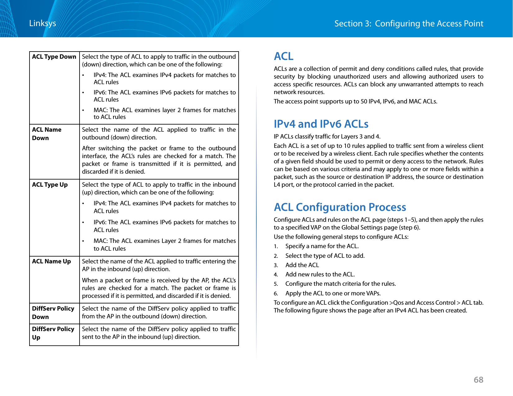
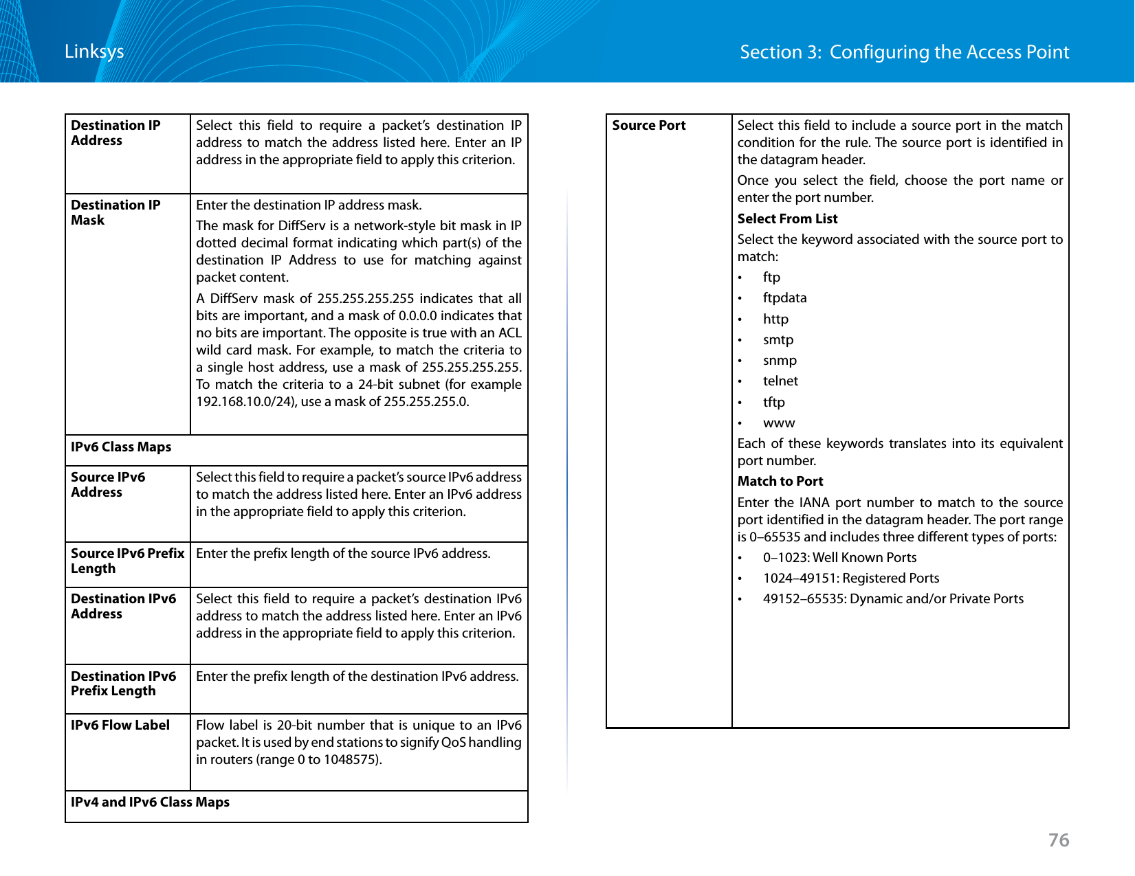
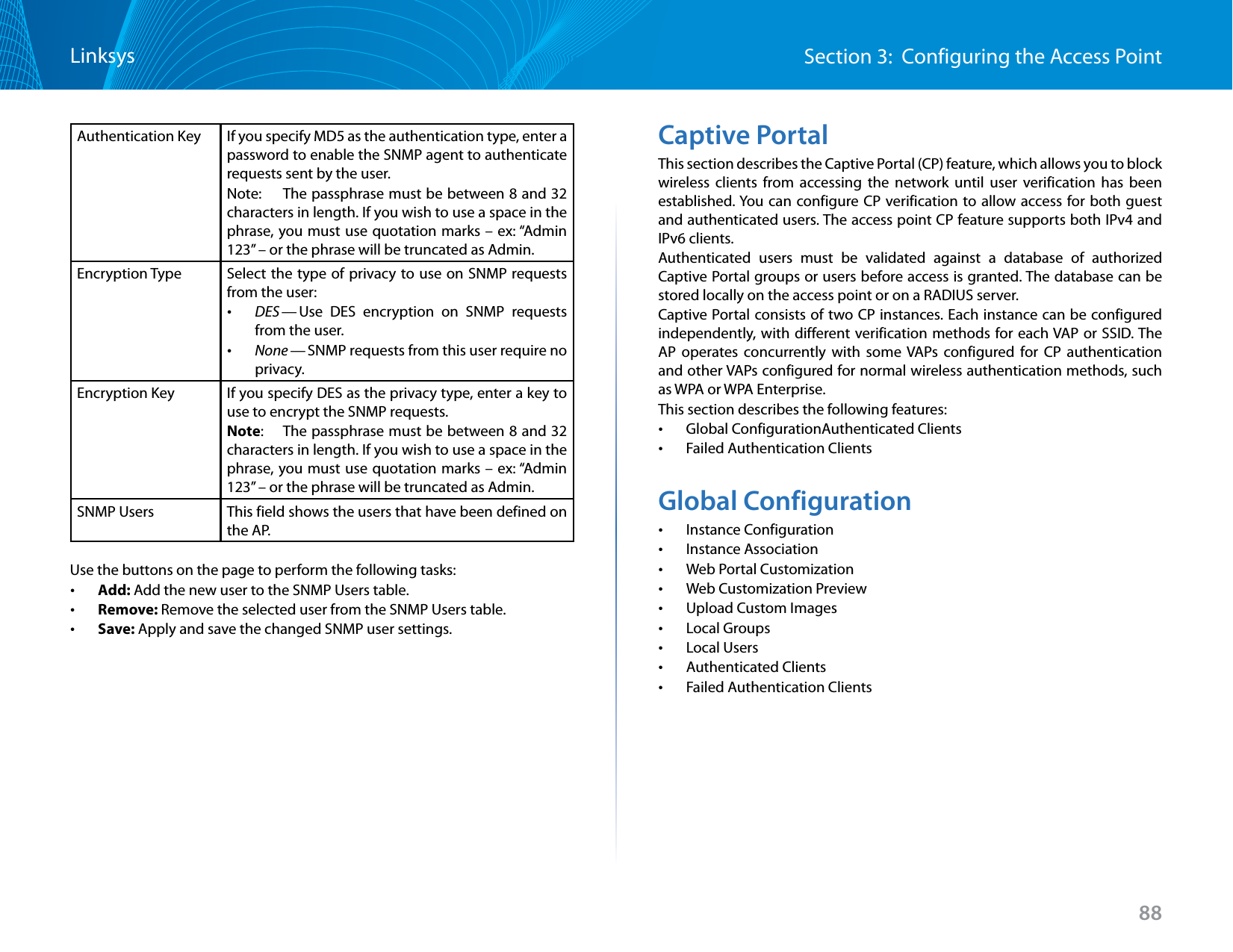
![25Section 3: Configuring the Access PointLinksysNOTE:After you configure the Email Alert settings, you must click Save to apply the changes and save the changes to startup configuration file. NOTE:Hostnames are composed of a series of labels joined with dots, as are all domain names. Each label must be between 1 and 63 characters long, and the entire hostname (including dots) has a maximum of 253 characters.To validate the configured email server credentials, click Test Mail. You can send a test email once the email server details are configured.The following text shows an example of an email alert sent from the AP to the network administrator:From: AP-192.168.2.10@mailserver.com Sent: Wednesday, February 08, 2012 11:16 AMTo: administrator@mailserver.comSubject: log message from APTIME Priority Process Id MessageFeb 8 03:48:25 info login[1457] root login on ‘ttyp0’Feb 8 03:48:26 info mini_http-ssl[1175] Max concurrent connections of 20 reached on current connections of 20 reachedManagement AccessYou can create an access control list (ACL) that lists up to five IPv4 hosts and five IPv6 hosts that are authorized to access the AP management interface. If this feature is disabled, anyone can access the management interface from any network client by supplying the correct AP user name and password.Figure 17: Management AccessTable 20: Management AccessField DescriptionManagement ACL ModeEnable or disable the management ACL feature. At least one IPv4 or IPv6 address should be configured before enabling Management ACL Mode. If enabled, only the IP addresses you specify will have Web, Telnet, SSH, and SNMP access to the management interface.IP Address (1–5)Enter up to five IPv4 addresses that are allowed management access to the AP. Use dotted-decimal format (for example, 192.168.10.10).IPv6 Address (1–5)Enter up to five IPv6 addresses that are allowed management access to the AP. Use the standard IPv6 address format (for example 2001:0db8:1234::abcd).NOTE:After you configure the settings, click Save to apply the changes and to save the settings.](https://usermanual.wiki/LINKSYS/LAPAC1750PO.User-Manual-1/User-Guide-2258455-Page-27.png)
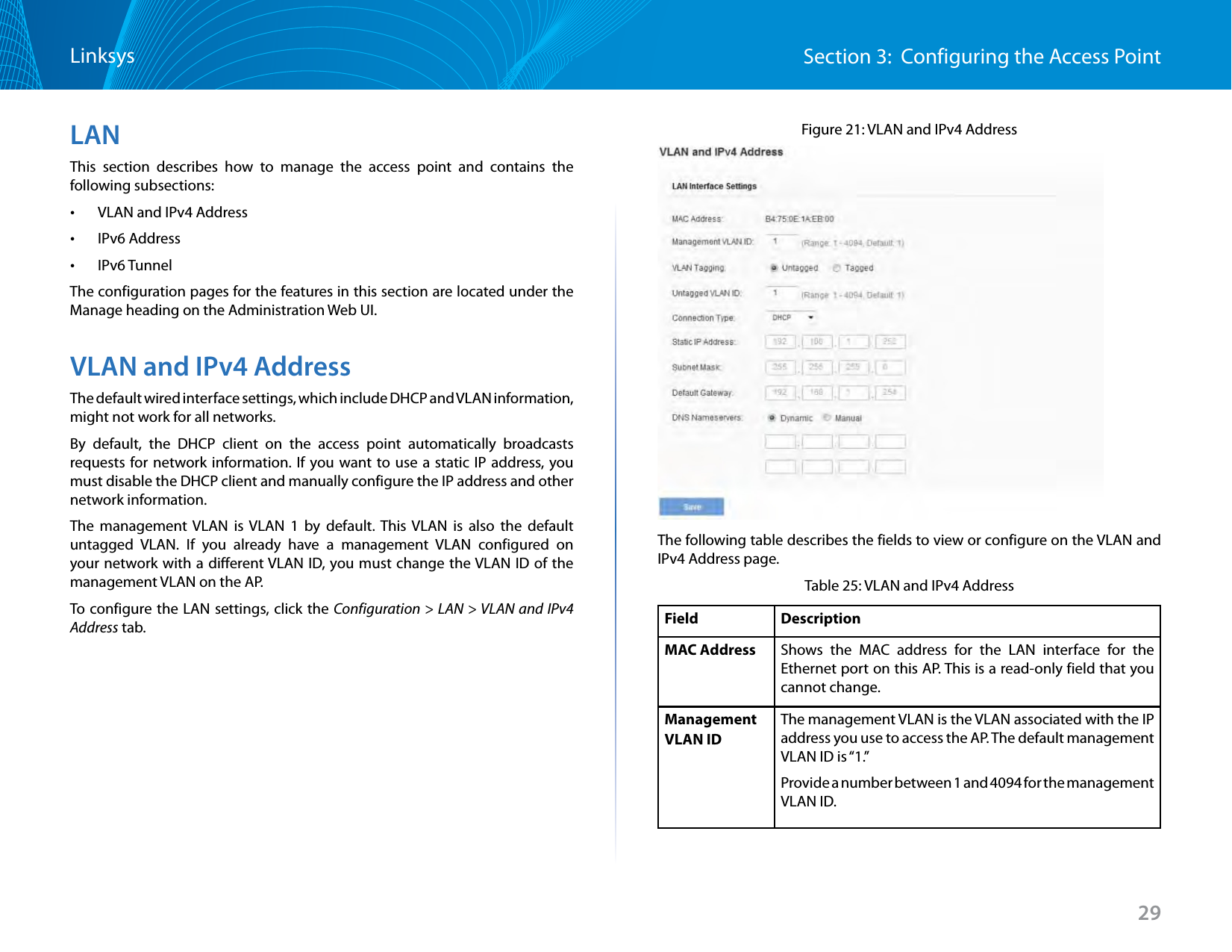
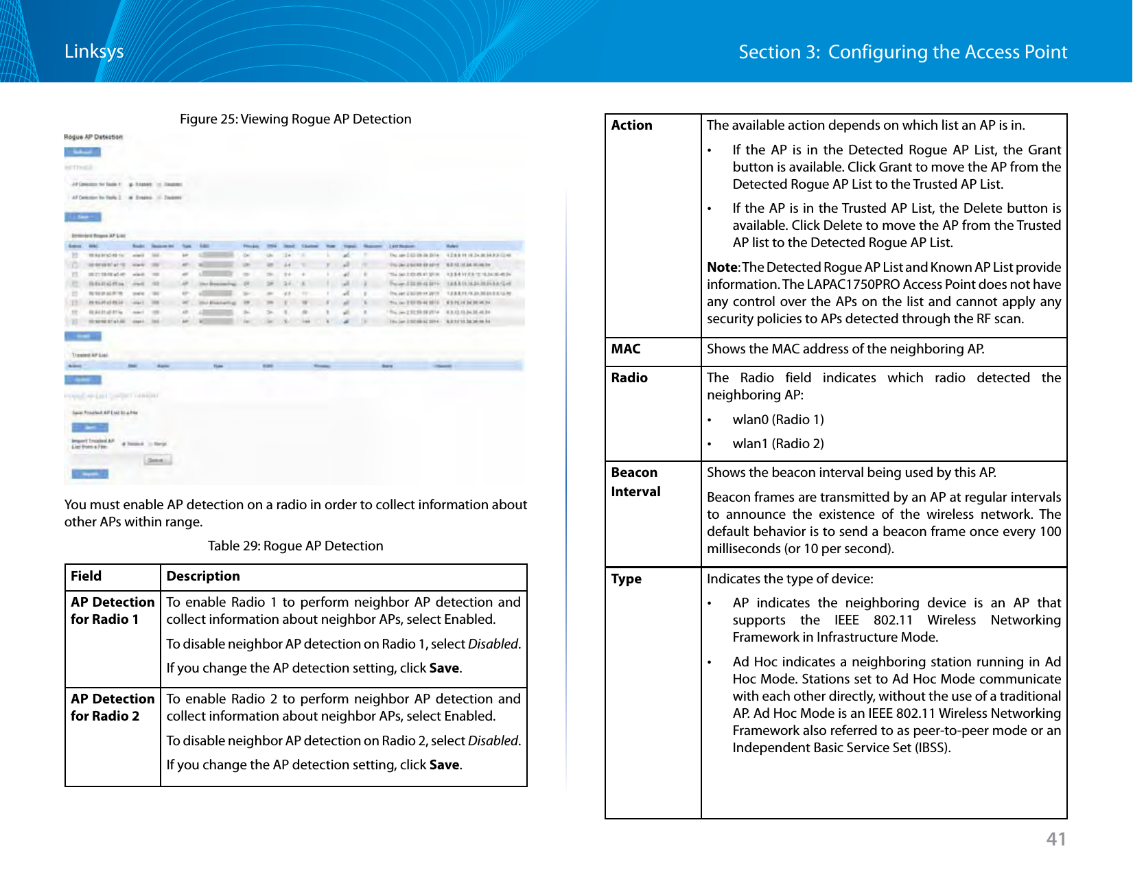
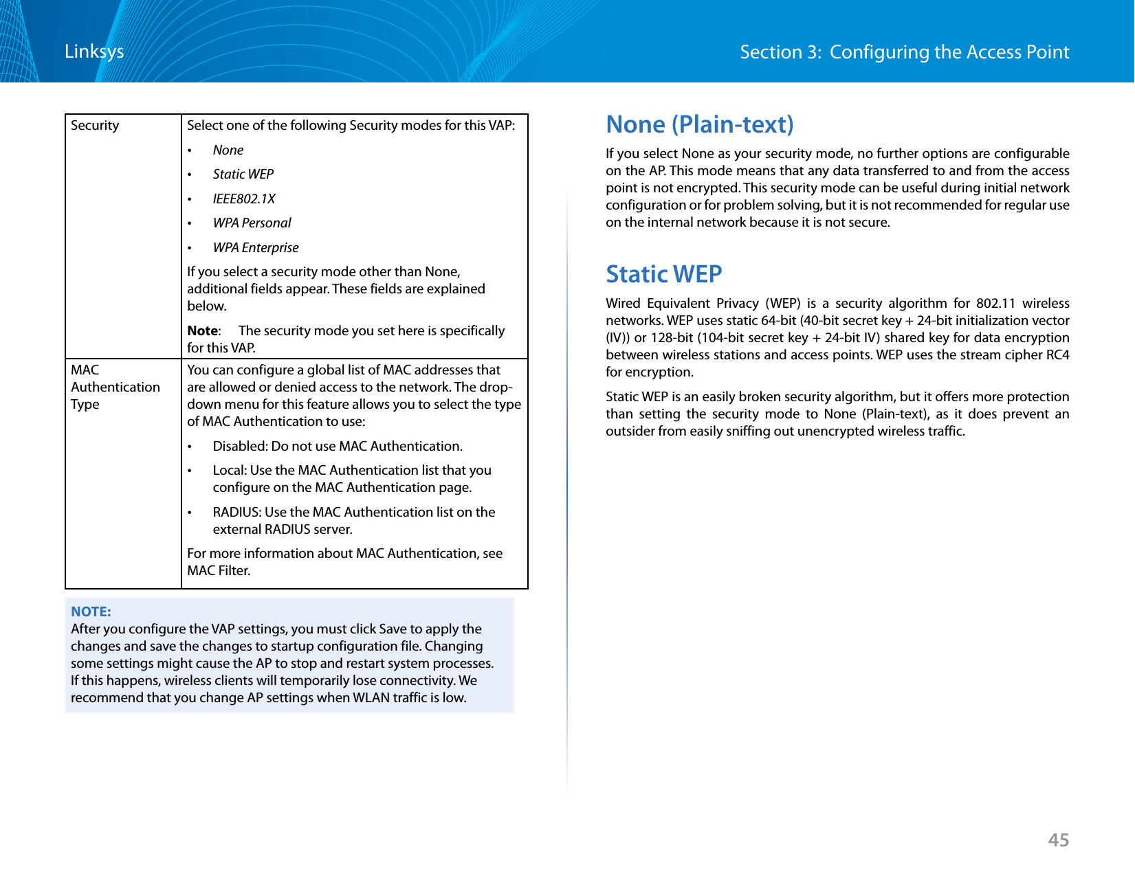
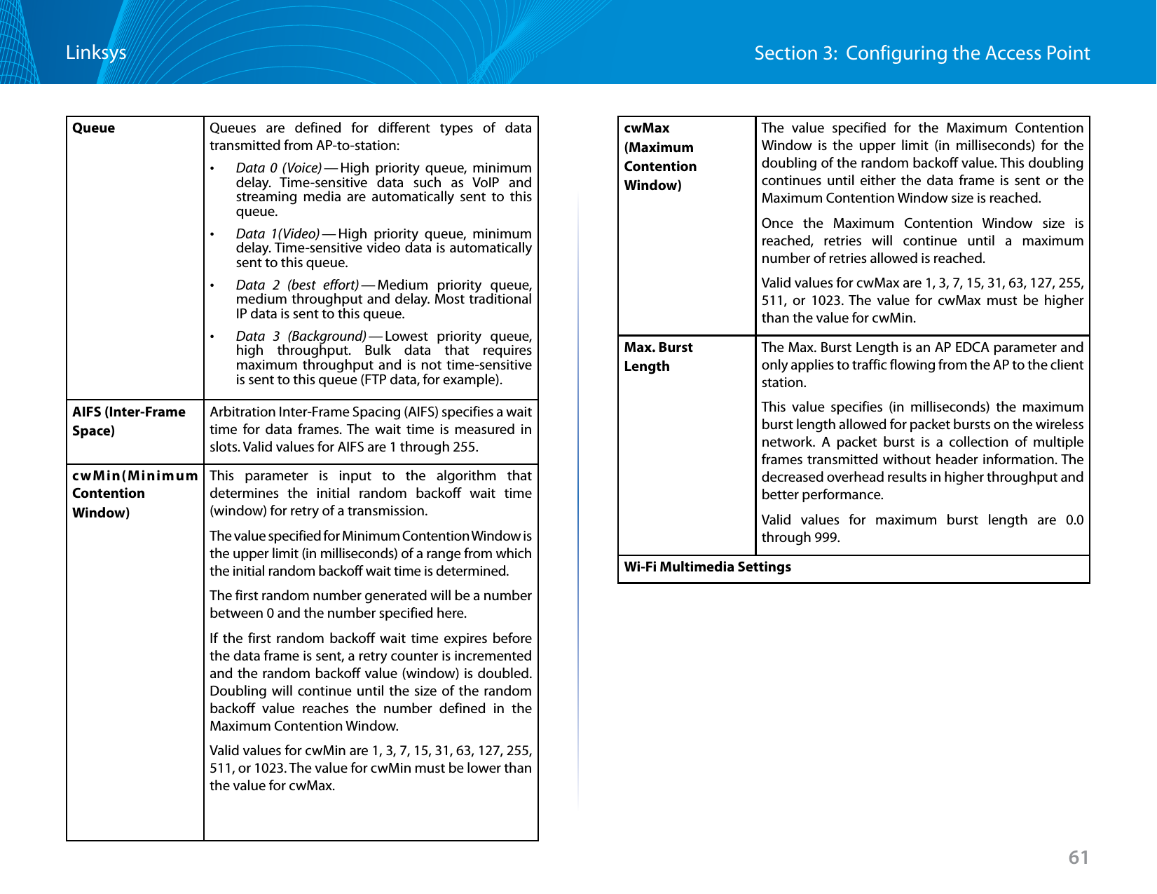
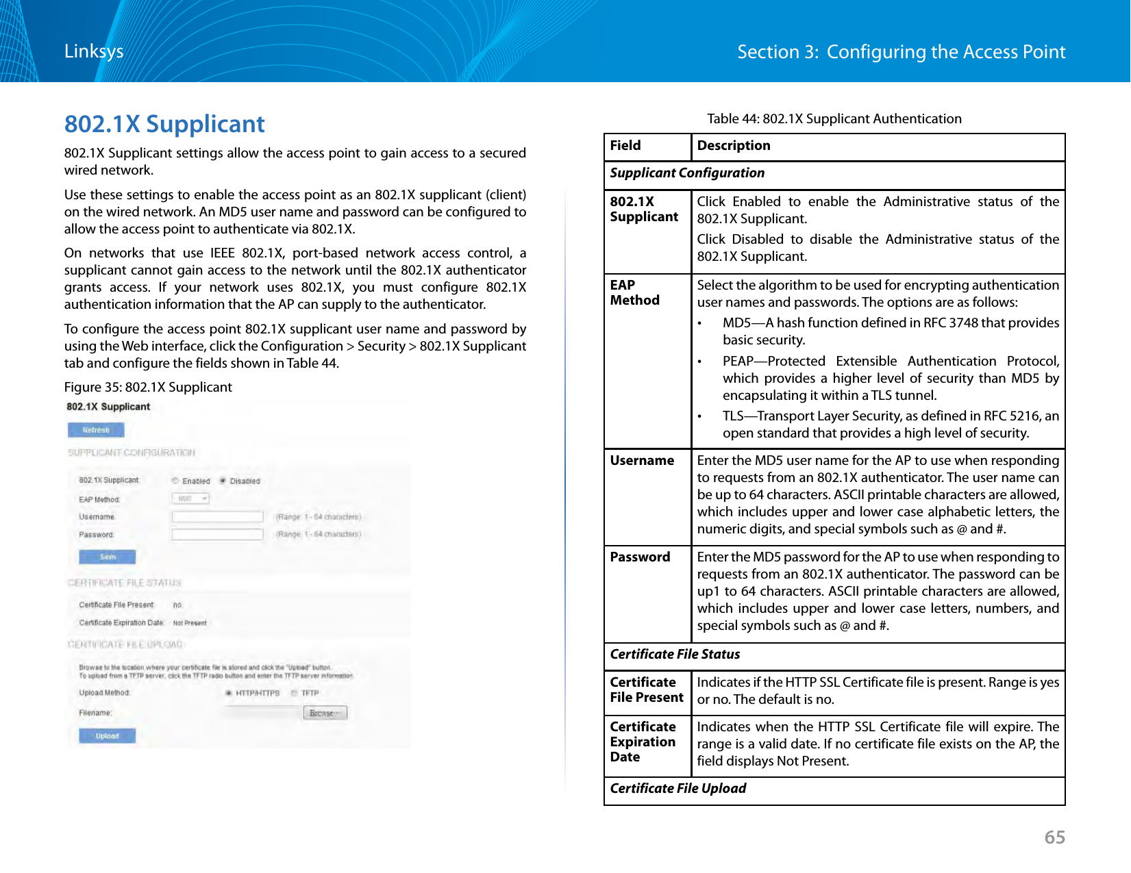
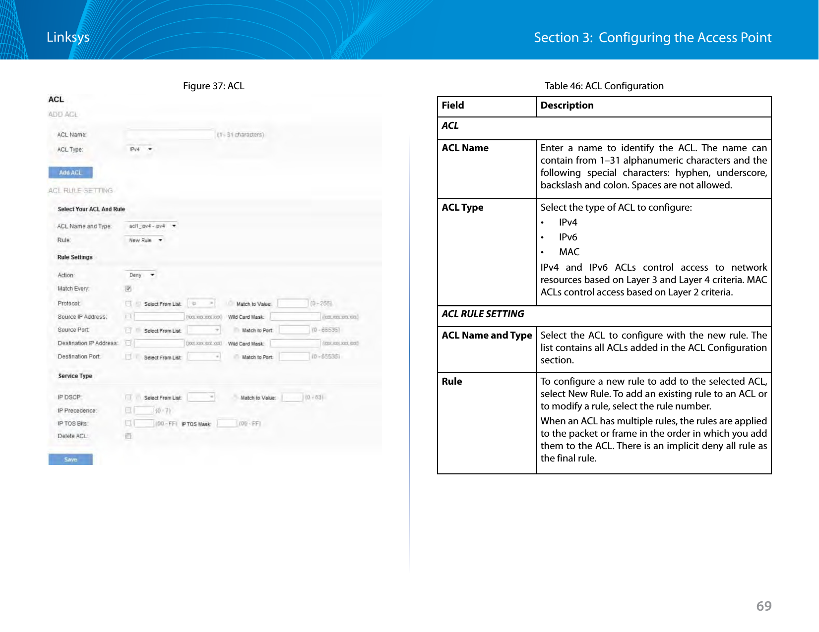
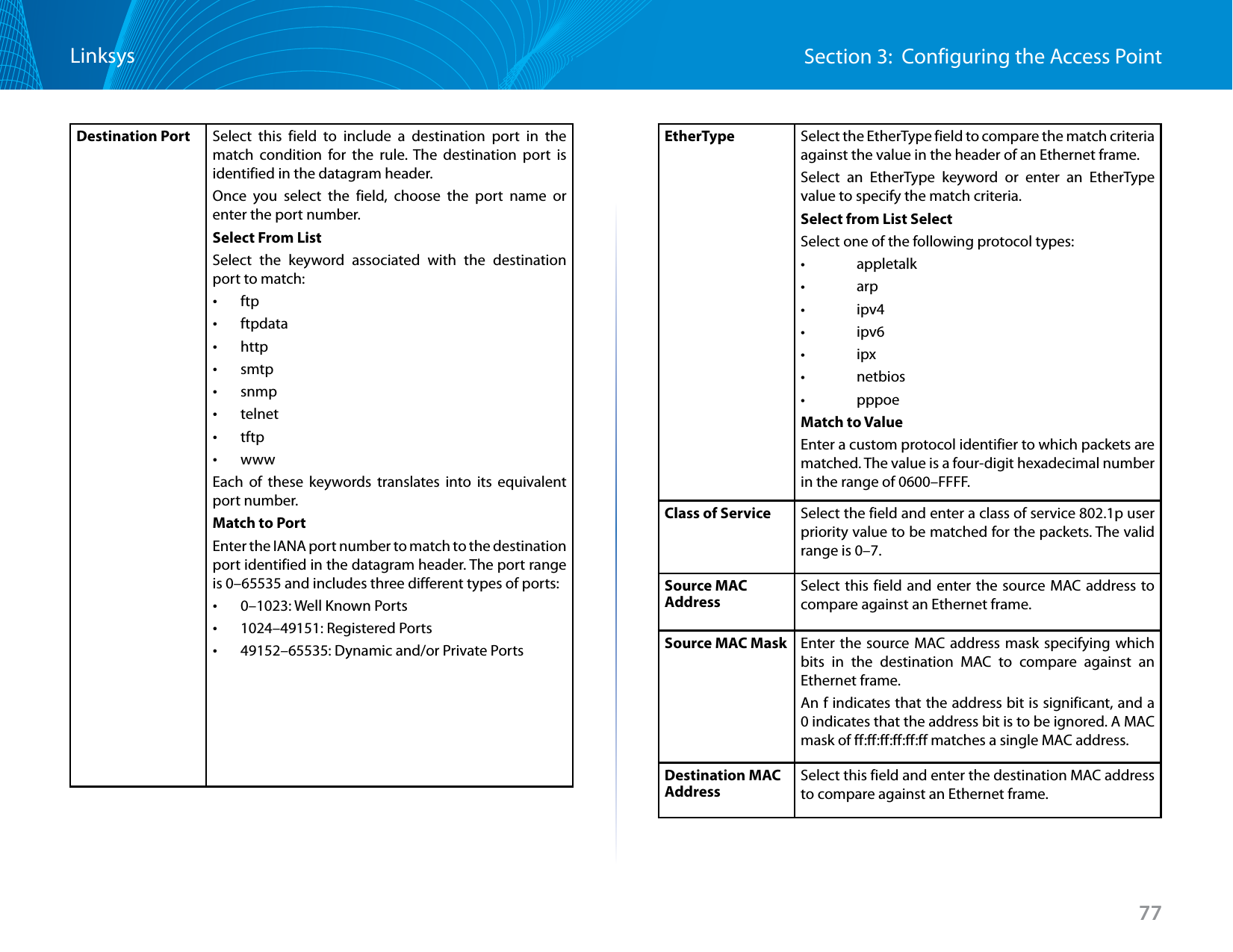
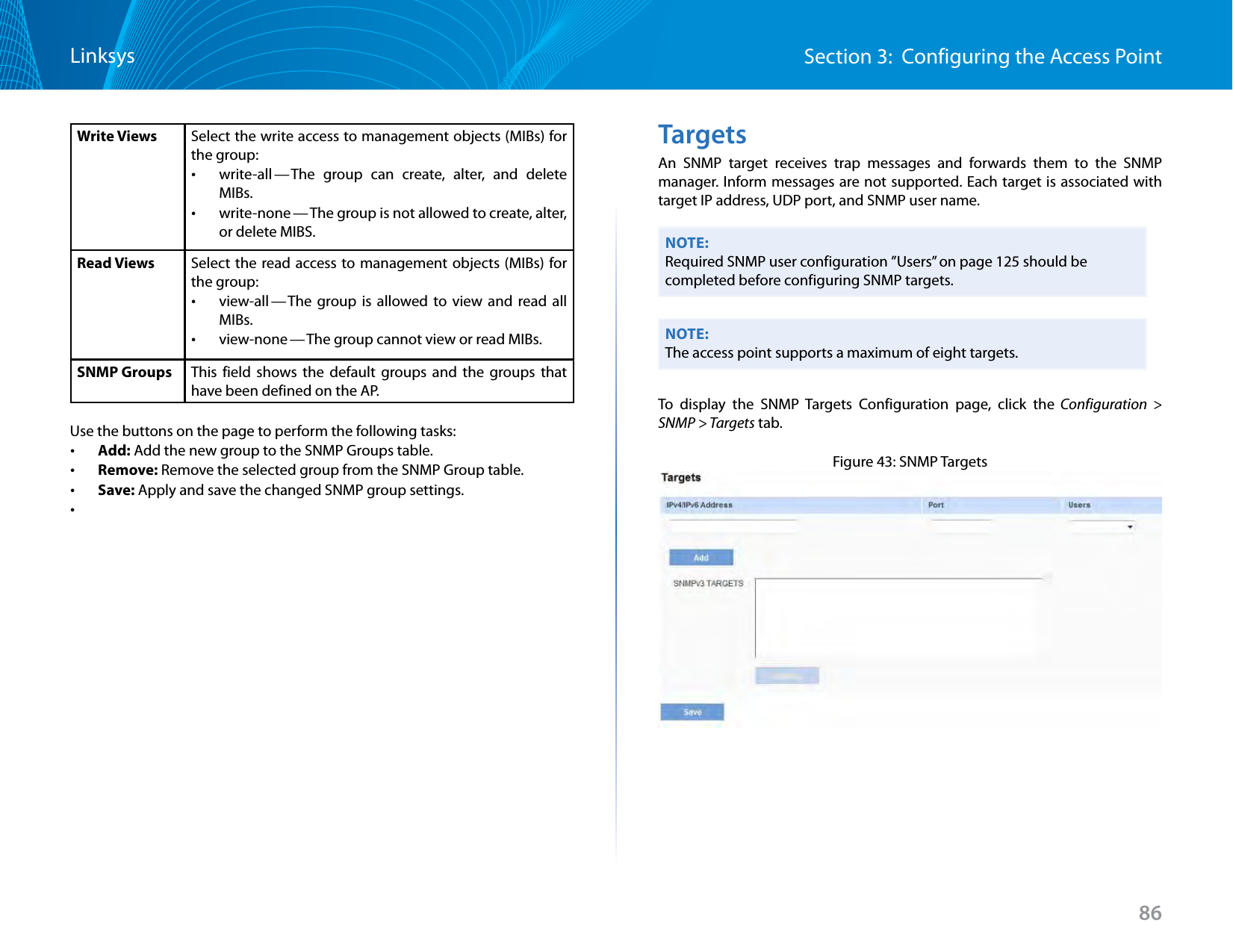
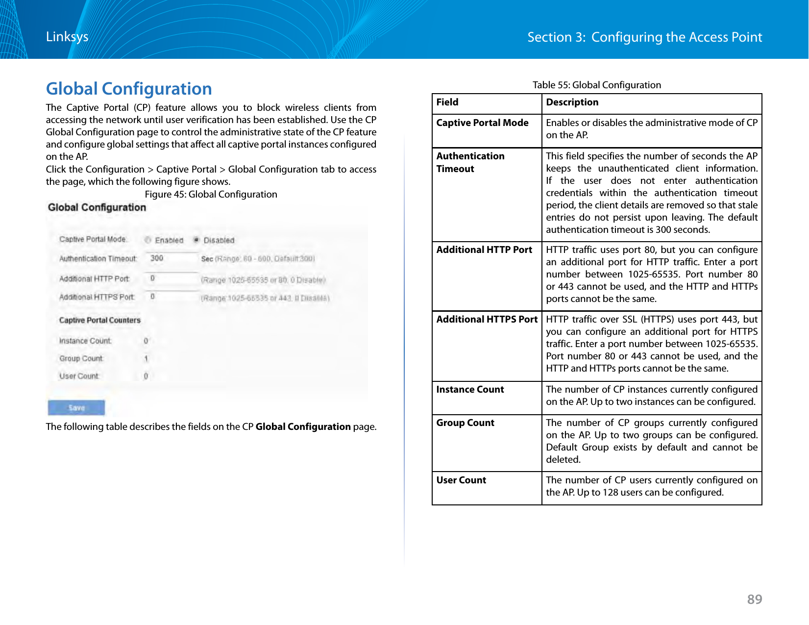
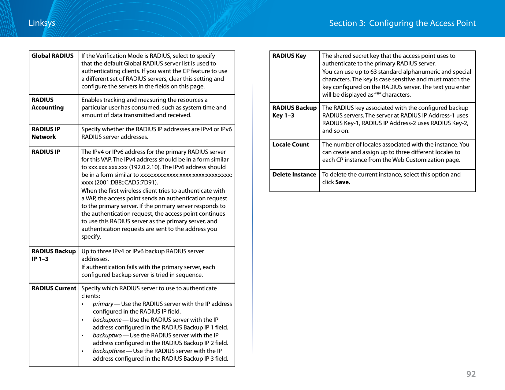
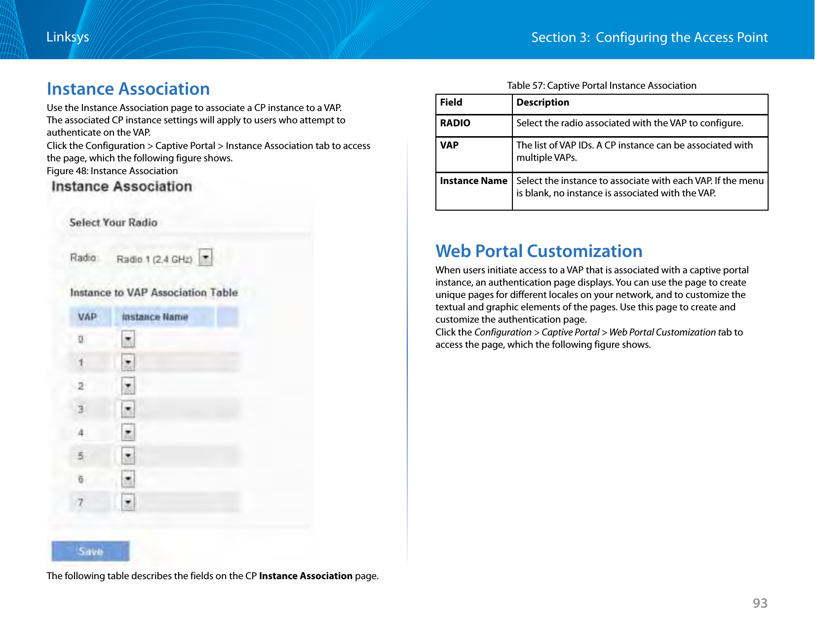
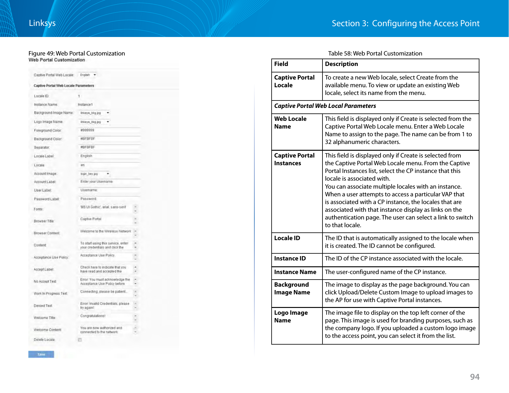
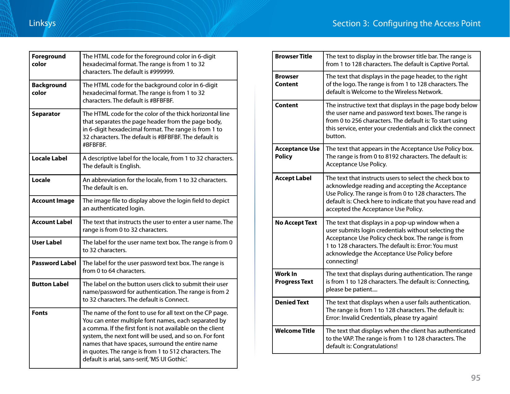
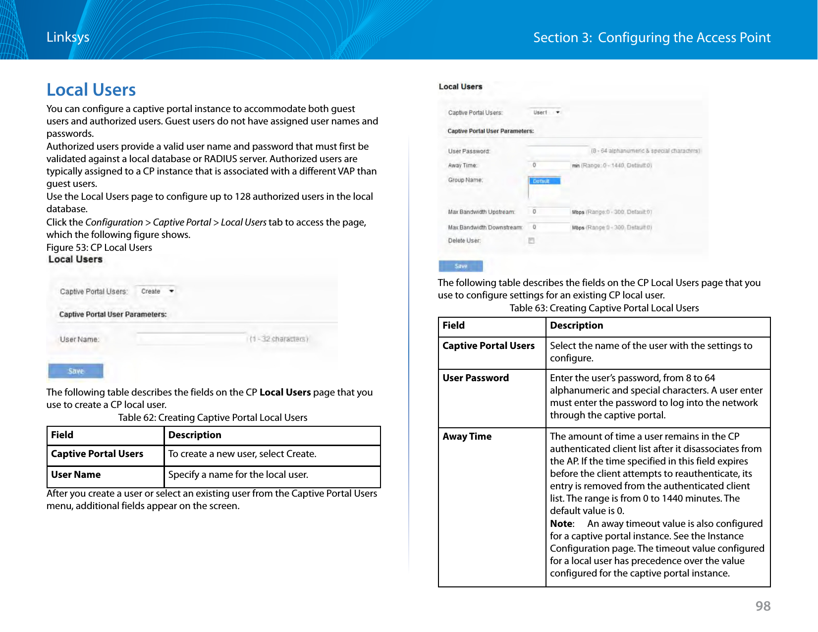
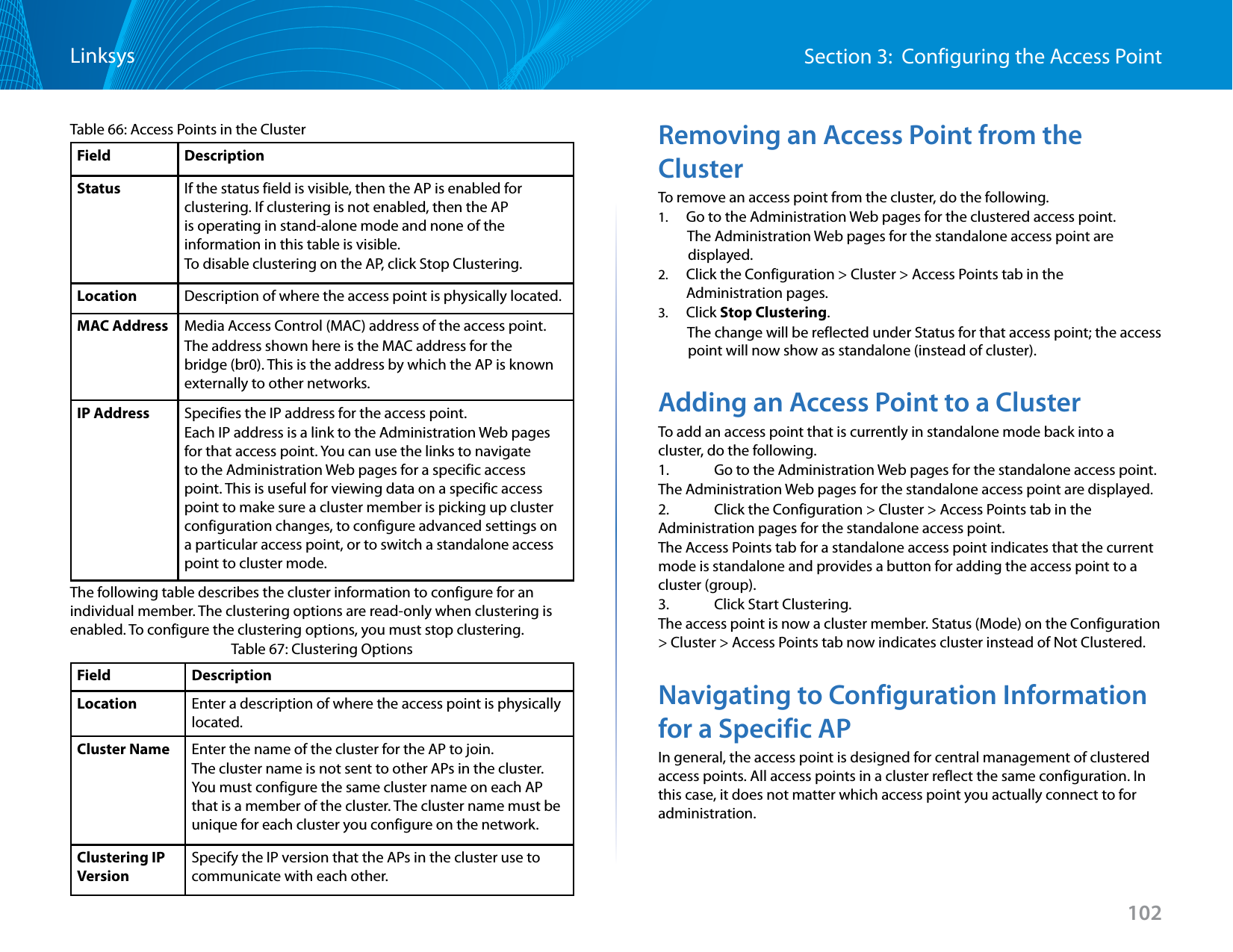
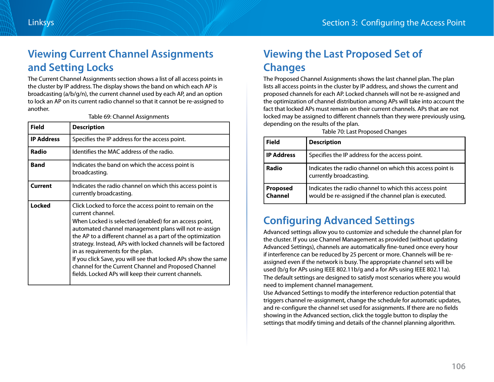
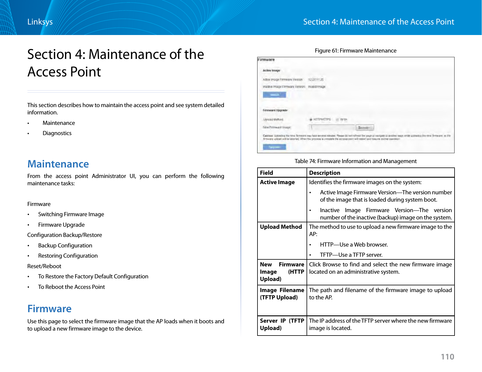
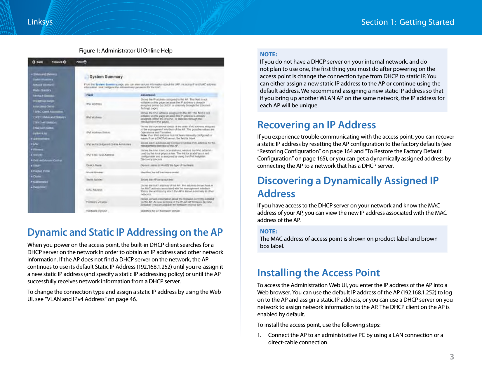
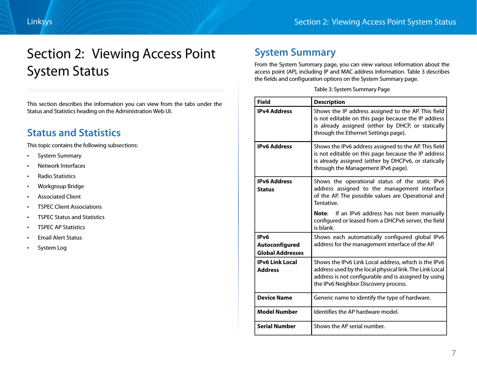
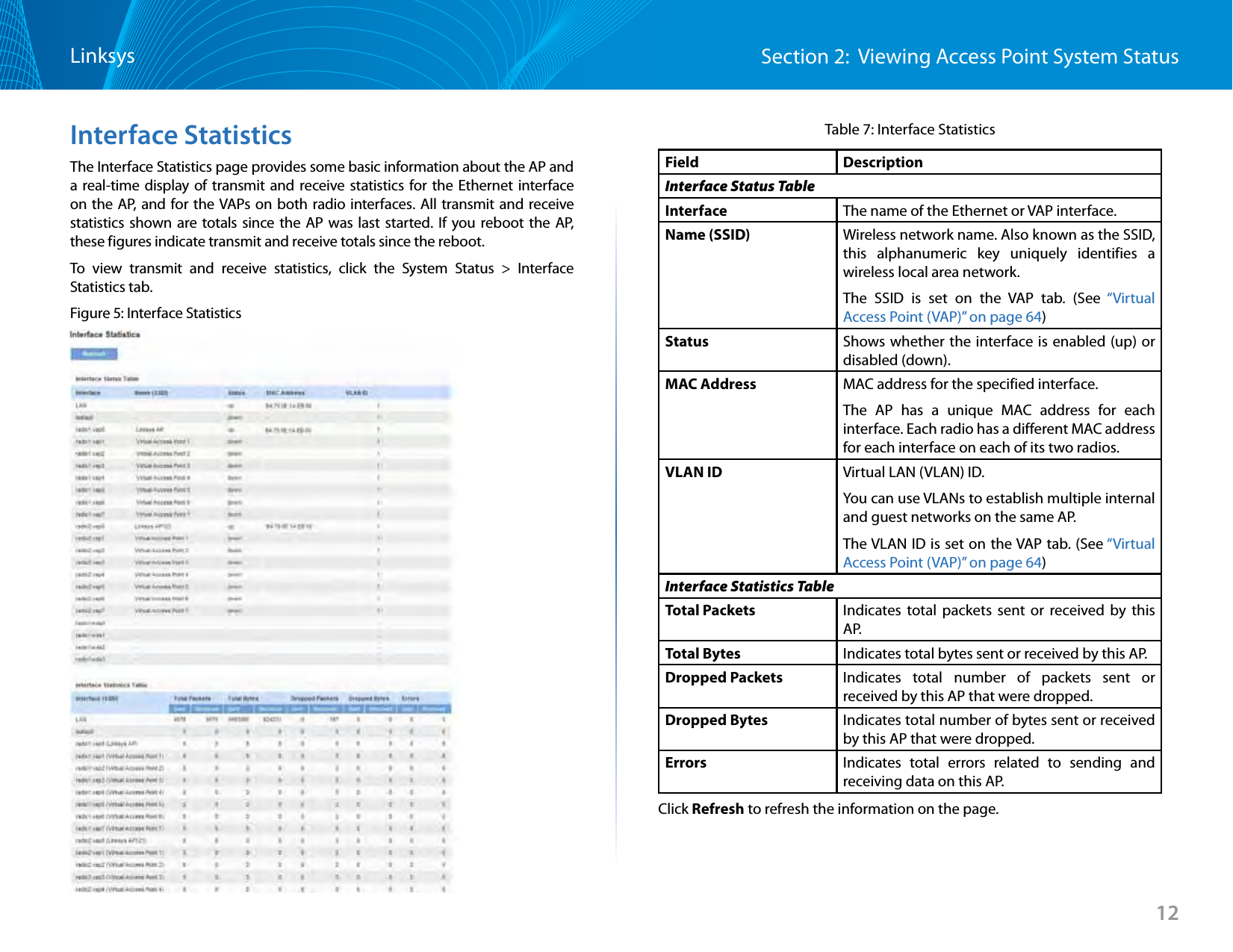
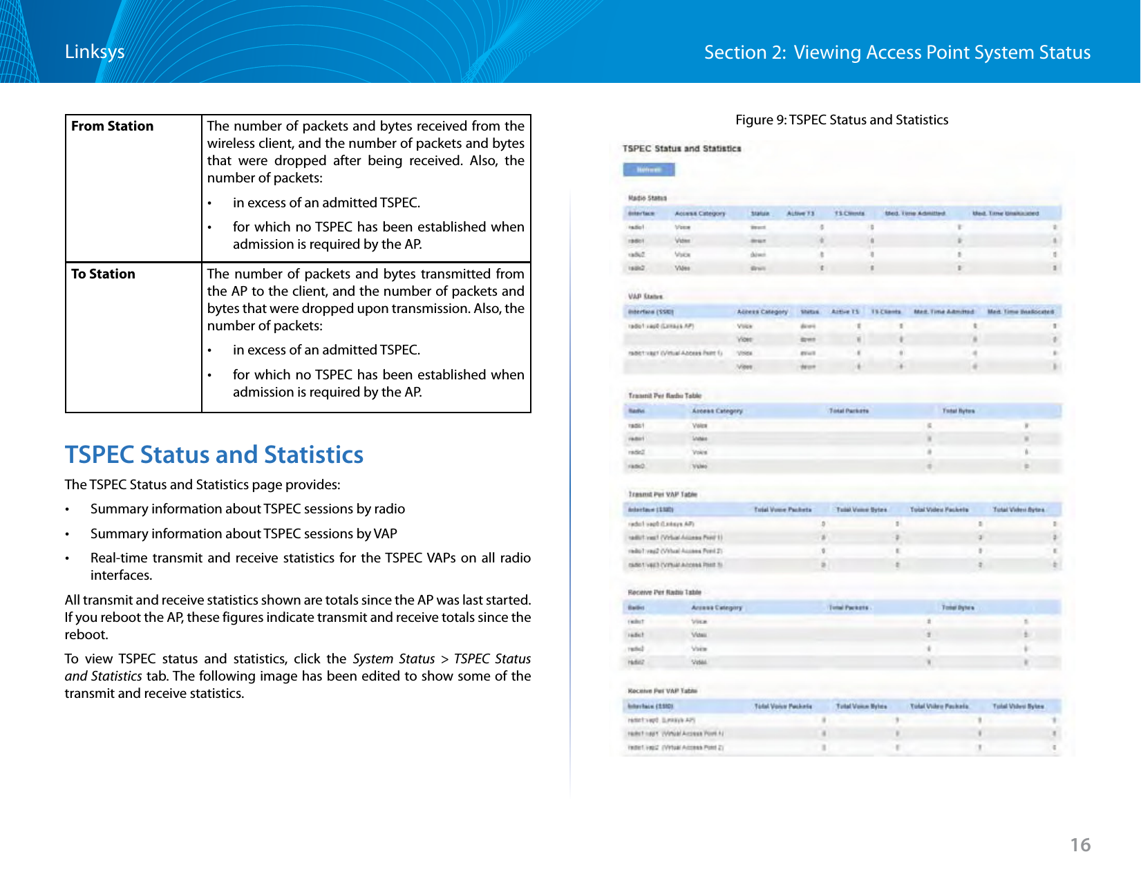
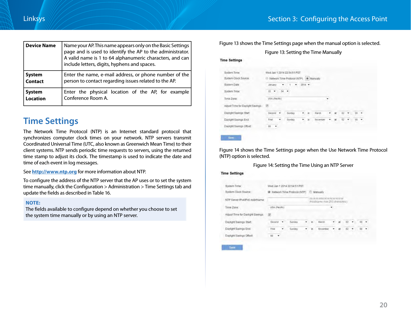
![91Section 3: Configuring the Access PointLinksysTable 56: Captive Portal Instance ConfigurationField DescriptionCaptive Portal InstancesSelect an existing instance to view or configure its settings, or select Create to configure a new CP instance. The access point supports two instances. If both instances have been configured, you must delete an instance before you can create a new one.Instance Name This field is available only if Create is selected from the Captive Portal Instances field. Specify a name for the new CP instance.Instance ID The CP instance identifier. For an existing instance, this field cannot be configured. When creating a new CP instance, the ID cannot be used by another CP instance. If you attempt to assign an Instance ID that is in use, an error message is displayed.Admin Mode Select the option to enable the administrative mode of the selected CP instance, or clear the option to disable it.Protocol Specifies HTTP or HTTPs as the protocol for the CP instance to use during the verification process.Verification The authentication method for CP to use to verify clients: •Guest—The user does not need to be authenticated by a database. •Local—The Access Point uses a local database to authenticated users. •RADIUS—The Access Point uses a database on a remote RADIUS server to authenticate users.Redirect Specifies that CP should redirect the newly authenticated client to the configured URL. If this option is clear, the user sees the locale-specific welcome page after a successful verification. Redirect URL Enter the URL (including http://), either IPv4 or an IPv6 address, to which the newly authenticated client is redirected if the URL Redirect Mode is enabled. The IPv4 address should be in a form similar to http://xxx.xxx.xxx.xxx (http://192.0.2.10). The IPv6 address should be in a form similar to http://[xxxx:xxxx:xxxx:xxxx::xxxx:xxxx:xxxx:xxxx] (http://[2001:DB8::CAD5:7D91]). The range is from 0 to 256 characters.Away Time The amount of time a user remains in the CP authenticated client list after it disassociates from the AP. If the time specified in this field expires before the client attempts to reauthenticate, its entry is removed from the authenticated client list. The range is from 0 to 1440 minutes. The default value is 60 minutes.Note: An away timeout value is also configured for each user. See the Local Users page. The user’s away timeout value has precedence over the value configured here.Session TimeoutThe amount of time to wait before terminating a session. A user is logged out after the session timeout is reached. If the value is set to 0, the timeout is not enforced. The range is from 0 to 1440 minutes. The default value is 0.Max Bandwidth UpstreamThe maximum upload speed, in megabits per second, that a client can transmit traffic when using the captive portal. This setting limits the bandwidth at which the client can send data into the network. The range is from 0 to 300 Mbps. The default value is 0.Max Bandwidth DownstreamThe maximum download speed, in megabits per second, that a client can receive traffic when using the captive portal. This setting limits the bandwidth at which the client can receive data from the network. The range is from 0 to 300 Mbps. The default value is 0.User Group NameThe user group associated with this instance. Each CP user is associated with a group, and a group is associated with a CP instance.](https://usermanual.wiki/LINKSYS/LAPAC1750PO.User-Manual-1/User-Guide-2258455-Page-93.png)