LINKSYS LAPN300 Wireless-N300 Access Point with PoE User Manual 0506085
LINKSYS LLC Wireless-N300 Access Point with PoE 0506085
LINKSYS >
User Manual.pdf

LAPN300
Wireless-N300
Access Point with PoE
User's Guide

i
TABLE OF CONTENTS
CHAPTER 1 QUICK START GUIDE ................................................................................... 1
Package Contents .............................................................................................................. 1
Physical Details .................................................................................................................. 1
Mounting Guide ................................................................................................................. 3
CHAPTER 2 ACCESS POINT SETUP .................................................................................. 4
Overview ............................................................................................................................ 4
Setup using a Web Browser .............................................................................................. 4
Setup Wizard ..................................................................................................................... 6
User Accounts .................................................................................................................... 9
Time Screen ..................................................................................................................... 10
Log Settings Screen ......................................................................................................... 12
Management Access Screen ............................................................................................ 14
SSL Certificate Screen .................................................................................................... 17
Network Setup Screen ..................................................................................................... 19
Advanced Screen ............................................................................................................. 21
Wireless Screens .............................................................................................................. 23
Basic Settings ................................................................................................................... 23
Security Settings .............................................................................................................. 25
Rogue AP Detection ........................................................................................................ 35
Scheduler .......................................................................................................................... 37
Scheduler Association ..................................................................................................... 39
Connection Control ......................................................................................................... 40
Rate Limit ........................................................................................................................ 41
QoS ................................................................................................................................... 42
Workgroup Bridge .......................................................................................................... 44
Advanced Settings ........................................................................................................... 46
CHAPTER 3 OPERATION AND STATUS ......................................................................... 49
Operation ......................................................................................................................... 49
System Summary ............................................................................................................. 49
LAN Status ....................................................................................................................... 51
Wireless Status ................................................................................................................. 53
Wireless Clients ............................................................................................................... 55
Statistics ........................................................................................................................... 56
Log View........................................................................................................................... 57
CHAPTER 4 ACCESS POINT MANAGEMENT ............................................................... 58
Overview .......................................................................................................................... 58
Firmware Upgrade .......................................................................................................... 58
Configuration ................................................................................................................... 60
Factory Default ................................................................................................................ 62
Reboot ............................................................................................................................... 63
Ping Test ........................................................................................................................... 64
Packet Capture ................................................................................................................ 65
Diagnostic Log ................................................................................................................. 66
APPENDIX A TROUBLESHOOTING ................................................................................ 67
Overview .......................................................................................................................... 67
General Problems ............................................................................................................ 67
APPENDIX B ABOUT WIRELESS LANS .......................................................................... 69
Overview .......................................................................................................................... 69
Wireless LAN Terminology ............................................................................................ 69
ii
APPENDIX C PC AND SERVER CONFIGURATION ........................................................ 72
Overview .......................................................................................................................... 72
Using WEP ....................................................................................................................... 72
Using WPA2-PSK ............................................................................................................ 73
Using WPA2-Enterprise ................................................................................................. 74
802.1x Server Setup (Windows 2000 Server) ................................................................ 75
802.1x Client Setup on Windows XP ............................................................................. 85
Using 802.1x Mode (without WPA) ............................................................................... 91
REGULATORY APPROVALS ............................................................................................. 92
Federal Communication Commission Interference Statement ................................... 92
Radiation Exposure Statement....................................................................................... 92
Industry Canada statement ............................................................................................ 92
Radiation Exposure Statement....................................................................................... 92
Déclaration d'exposition aux radiations ........................................................................ 93
Copyright © 2013. All Rights Reserved.
Document Version: 1.0
All trademarks and trade names are the properties of their respective owners.

1
Chapter 1
Quick Start Guide
Package Contents
• Linksys Wireless Access Point
• Quick Start Guide
• Ethernet Cable
• AC Power Adapter
• CD with Documentation
• Mounting Bracket
• Mounting Kit
• Ceiling Mount Back Plate
• Drilling Layout Template
Physical Details
There is one LED for the device.
LED
LED Color Activity Status
Green Blinking System is booting.
Solid System is normal; no wireless device connected.
Blue Blinking Software upgrade in process.
Solid System is normal; at least one wireless device connected.
Red
Blinking Ethernet connection is not working.
Solid Booting process or update failed; hard reset or service re-
quired.
Port and Button
Power Port - Connect the AC power adapter to this port.
NOTE: Use only the adapter that came with your access point.
Ethernet Port - Connect a wired network device to this port. This port supports PoE (Power
over Ethernet) with a PoE switch or PoE injector. LAPN300 can be powered on from an
802.3af/802.3at compliance source, and LAPN300 is powered on from an 802.3at compliance
source.
1
2
NOTE: If connected to a PoE switch or PoE injector, PoE will take precedence over an AC
power adapter.
Reset Button - Press and hold this button for less than 15 seconds to power cycle device. Press
and hold for longer than 15 seconds to reset the device to factory default settings.
3
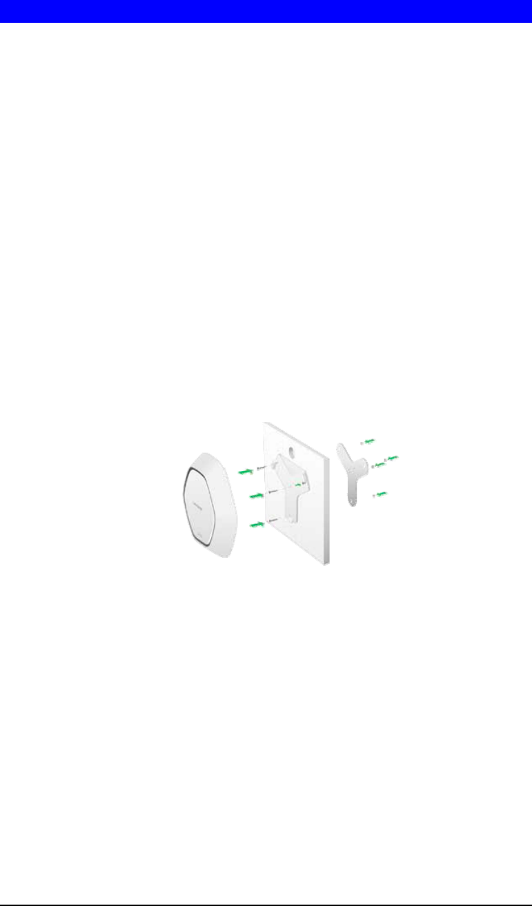
Mounting Guide
To avoid overheating, do not install your access point if ambient temperatures exceed 104°F
(40°C). Install on a flat, stable surface, near the center of your wireless coverage area making
sure not to block vents on the sides of the device enclosure.
Wall Installation
1. Position drilling layout template at the desired location.
2. Drill four screw holes on the mounting surface. If your Ethernet cable is routed be-
hind the wall, mark Ethernet cable hole as well.
3. Secure the mounting bracket on the wall with anchors and screws.
4. If your Ethernet cable is routed behind the wall, cut or drill the Ethernet cable hole
you marked in Step 2. Feed the Ethernet cable through the hole.
5. Connect the Ethernet cable and/or AC power adapter to your device.
6. Slide the device into the bracket. Turn clockwise until it locks into place.
Ceiling Installation
1. Select ceiling tile for mounting and remove tile.
2. Position drilling layout template at the desired location.
3. Drill four screw holes and Ethernet cable hole on the surface of ceiling tile..
4. Place back plate on the opposite side of ceiling tile. Secure mounting bracket to the
ceiling tile with flathead screw and nut. Route the Ethernet cable through the Ethernet
cable hole.
5. Replace tile in ceiling.
6. Connect the Ethernet cable and/or AC power adapter to your device
7. Slide the device into the bracket. Turn access point clockwise until it locks.
IMPORTANT
Improper or insecure mounting could result in damage to the device or personal injury.
Linksys is not responsible for damages caused by improper mounting.

4
Chapter 2
Access Point Setup
Overview
This chapter describes the setup procedure to connect the wireless access point to your LAN,
and configure it as an access point for your wireless stations.
Wireless stations may also require configuration. For details, see Appendix C - Wireless
Station Configuration.
The wireless access point can be configured using a Web browser.
Setup using a Web Browser
Your browser must support JavaScript. The configuration program has been tested on the
following browsers:
• Firefox 3.5 or later, Chrome 8 or later, Safari 5 or later
• Internet Explorer 7 or later
Setup Procedure
Before starting setup, install the wireless access point on your LAN, as described earlier.
1. Locate the wireless access point’s default name on a label on the base or rear. The default
name will be
lapxxxxx where
xxxxx is a set of the last 5 characters of your access point MAC Address. MAC Address
is available in the brown box label or product label.
2. Use a PC connected to your LAN, either by a wired connection or another access point.
Until the wireless access point is configured, establishing a wireless connection to it may
be not possible.
If your LAN contains a router or routers, ensure the PC used for configuration is on the
same LAN segment as the wireless access point.
3. Start your Web browser.
4. Enter the IP address of the wireless access point, as in this example, which uses the
wireless access point's default IP address:
http://192.168.1.252
At the login prompt, enter admin for the User name, and admin for the Password.
These are the default values. You should change the password.
2

5
Figure 1: Password Dialog
5. From the status screen menu configure for your environment. Details of these screens and
settings are described in the following sections of this chapter.
6. You may also wish to change the admin password on the User Accounts screen, accessed
from the Configuration menu.
7. Wireless stations must now be set to match the wireless access point. See Chapter 4 for
details.
If you can't connect:
It is likely that your PC’s IP address is incompatible with the wireless access
point’s IP address. This can happen if your LAN does not have a DHCP Server.
The default IP address of the wireless access point is 192.168.1.252, with a
network mask of 255.255.255.0.
If your PC’s IP address is not compatible with this, you must change your PC’s IP
address to an unused value in the range 192.168.1.1 ~ 192.168.1.254, with a
network mask of 255.255.255.0. See Appendix A - Windows TCP/IP for details for
this procedure.
6
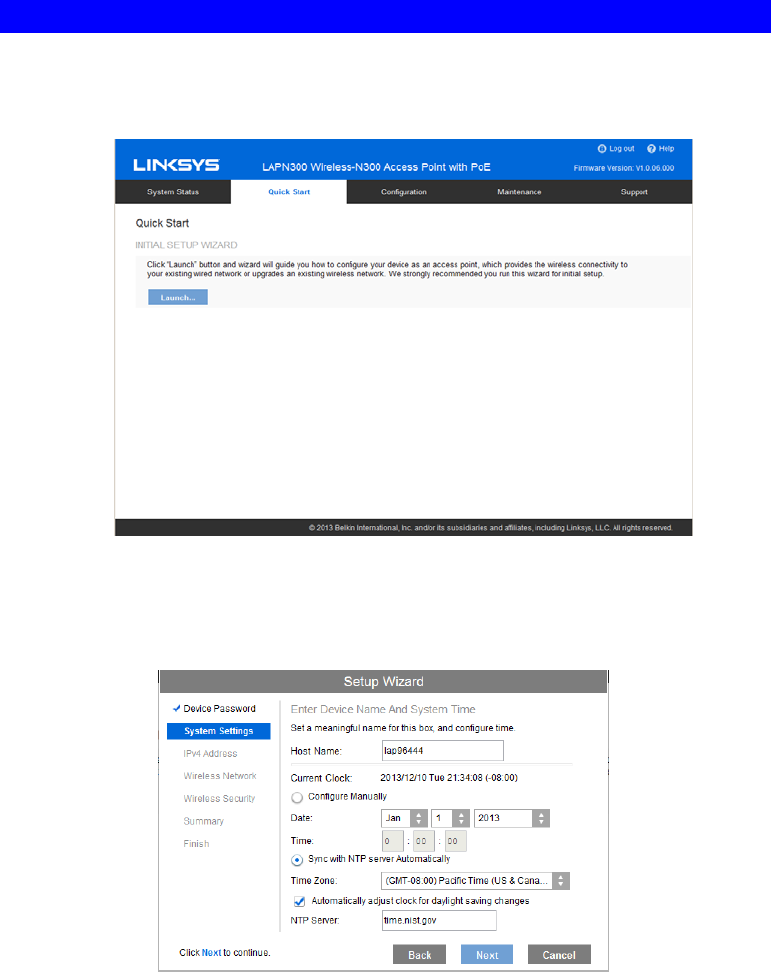
Setup Wizard
The first time you connect to the wireless access point, run the Setup Wizard to configure the
device.
1. Click the Quick Start link on the main menu
Figure 2: Setup Wizard
2. On the first screen, click Launch.
3. Set the password on the Device Password screen, if desired.
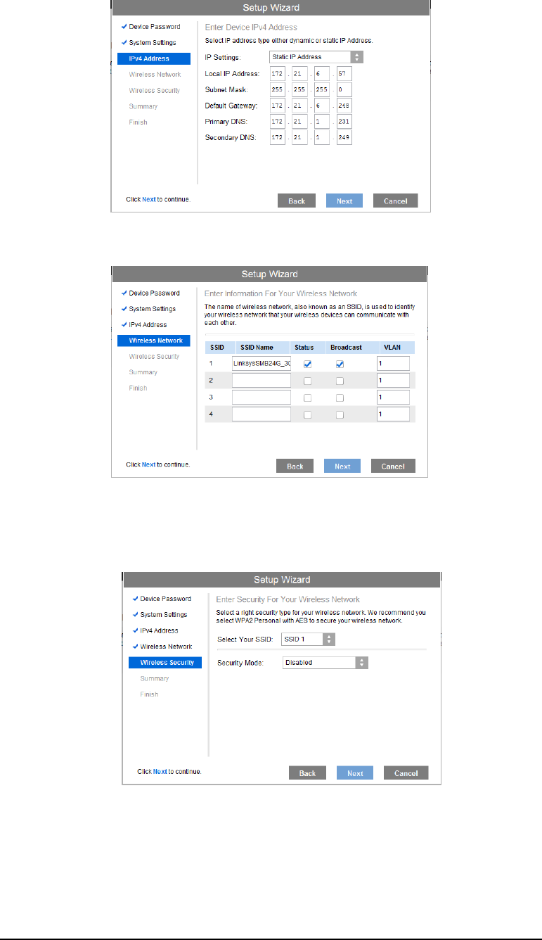
4. Configure the time zone, date and time for the device on System Settings screen.
Figure 3: Setup Wizard - System Settings
5. On the IPv4 Address screen (Figure 6) configure the IP address of the device then click
Next. If you want to configure more than 4 SSIDs, please go to Configuration->Wireless
->Basic Settings. The access point supports up to 8 SSIDs per radio.
7
Figure 4: Setup Wizard - IPv4
6. Set the SSID information on the Wireless Network screen. Click Next.
Figure 5: Setup Wizard - Wireless Network
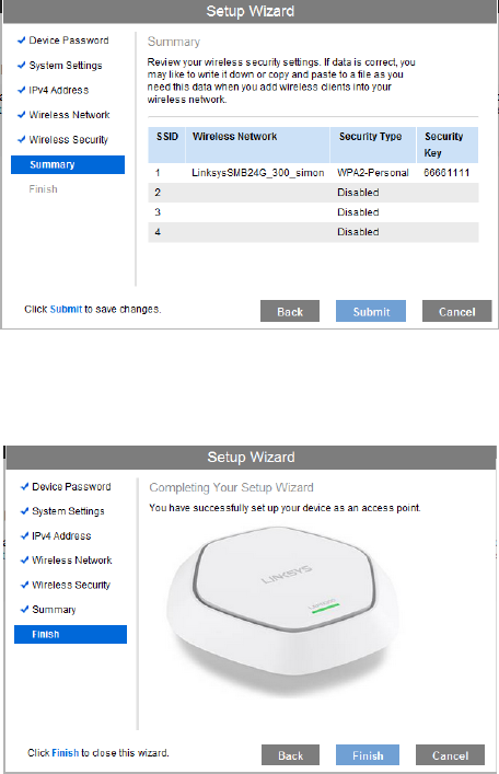
7. On the Wireless Security Screen (Figure 8) configure the wireless security settings for the
device. Click Next. If you are looking for security options that are not available in the wi-
zard, go to Configuration Æ WirelessÆ Security page. The access point supports more
sophisticated security options there.
Figure 6: Setup Wizard - Wireless Security
8
8. On the Summary screen, check the data to make sure they are correct and then click
Submit to save the changes.
Figure 7: Setup Wizard - Summary
9. Click Finish to leave the wizard.
Figure 8: Setup Wizard - Finish
9
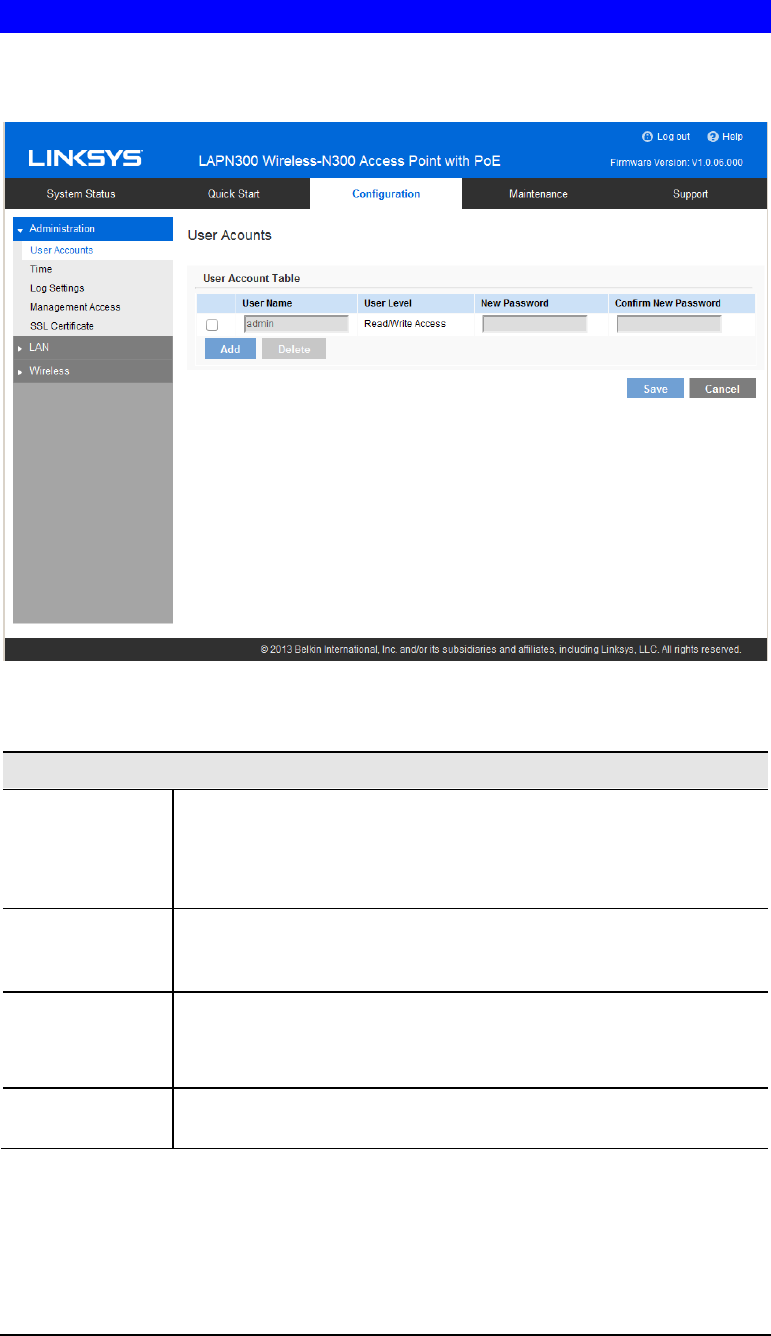
User Accounts
Click User Accounts on the Administration menu to manage user accounts. The access point
supports up to 5 users: one administrator and four normal users.
Figure 9: User Accounts
Data - User Accounts Screen
User Account Table
User Name Enter the User Name to connect to the access point’s admin interface.
User Name is effective once you save settings.
User Name can include up to 63 characters. Special characters are
allowed.
User Level Only administrator account has Read/Write permission to the access
point’s admin interface. All other accounts have Read Only permis-
sion.
New Password Enter the Password to connect to the access point’s admin interface.
Password must be between 4 and 63 characters. Special characters are
allowed.
Confirm New
Password Re-enter password.
10
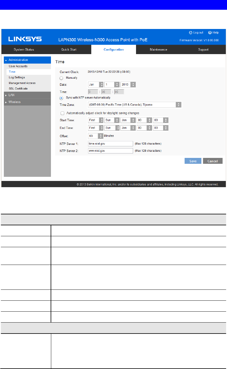
Time Screen
Click Time on the Administration menu to configure system time of the device.
Figure 10: Time Screen
Data - Time Screen
Time
Current Time Display current date and time of the system.
Manually Set date and time manually.
Automatically When enabled (default setting) the access point will get the current
time from a public time server.
Time Zone Choose the time zone for your location from the drop-down list. If
your location observes daylight saving time, enable “Automatically
adjust clock for daylight saving changes.”
Start Time Specify the start time of daylight saving.
End Time Specify the end time of daylight saving.
Offset Select the adjusted time of daylight saving.
NTP
NTP Server 1 Enter the primary NTP server. It can be an IPv4 address or a domain
name.
Valid characters include alphanumeric characters, "_", "-" and ".".
Maximum length is 64 characters.

11
NTP Server 2 Enter the secondary NTP server. It can be an IPv4 address or a domain
name.
Valid characters include alphanumeric characters, "_", "-" and ".".
Maximum length is 64 characters.
12
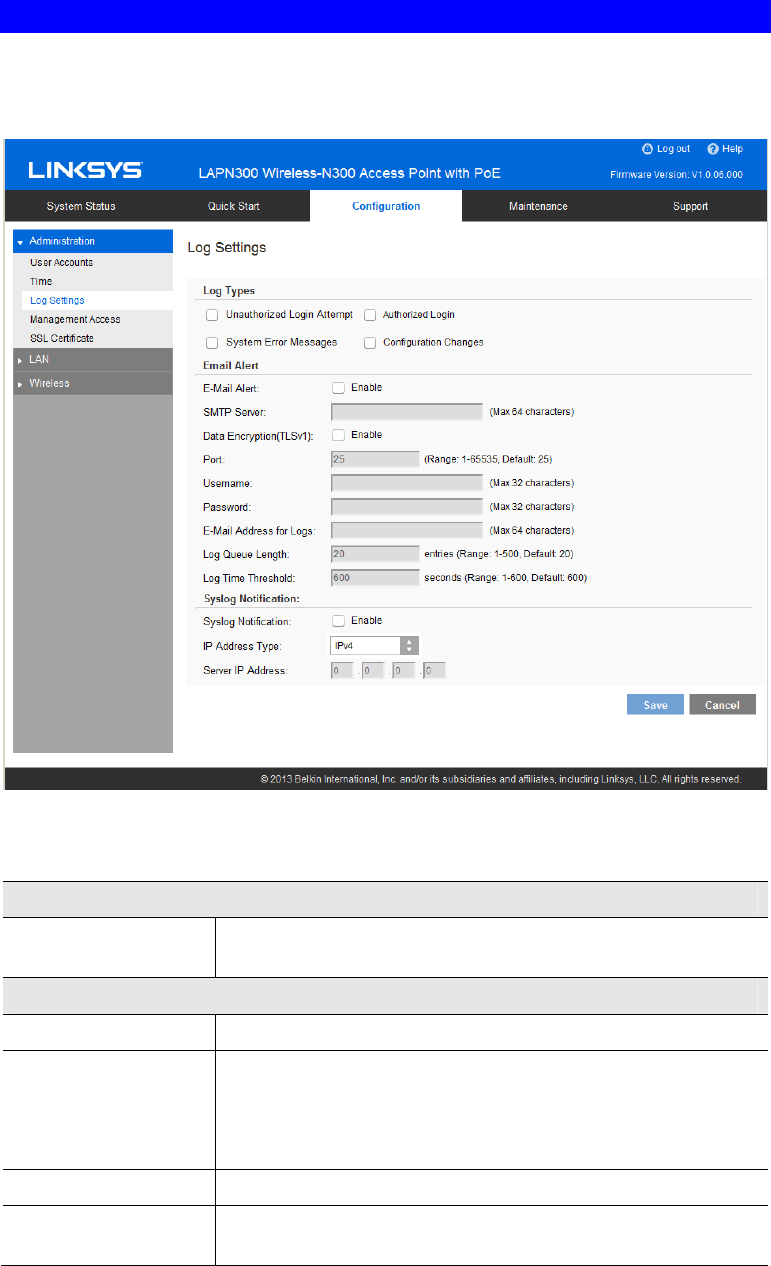
Log Settings Screen
The logs record various types of activity on the access point. This data is useful for trouble-
shooting, but enabling all logs will generate a large amount of data and adversely affect
performance.
Figure 11: Log Settings Screen
Data - Logs Screen
Log Types
Log Types Select events to log. Checking all options increase the size of the
log, so enable only events you believe are required.
Email Alert
Email Alert Enable email alert function.
SMTP Server Enter the e-mail server that is used to send logs. It can be an IPv4
address or a domain name.
Valid characters include alphanumeric characters, "_", "-" and ".".
Maximum length is 64 characters.
Data Encryption Enable if you want to use data encryption.
Port Enter the port for the SMTP server. The port is a value from 1 to
65535 and default is 25.

13
Username Enter the Username to login to your SMTP server.
The Username can include up to 32 characters. Special characters
are allowed.
Password Enter the Password to login to your SMTP server.
The Password can include up to 32 characters. Special characters
are allowed.
Email Address for
Logs Enter the email address the log messages are to be sent to.
Valid characters include alphanumeric characters, "_", "-", "." and
"@". Maximum length is 64 characters.
Log Queue Length Enter the length of the queue: up to 500 log messages. The
default is 20 messages. When messages reach the set length the
queue will be sent to the specified email address.
Log Time Threshold Enter the time threshold (in seconds) used to check if the queue is
full. It’s a value from 1 to 600 and default is 600 seconds.
Syslog
Syslog Notification Enable Syslog notification.
IP Type Select the IP type of the syslog server: IPv4 or IPv60029.
Server IP Address Enter the IPv4 or IPv6 address of syslog server here.
14
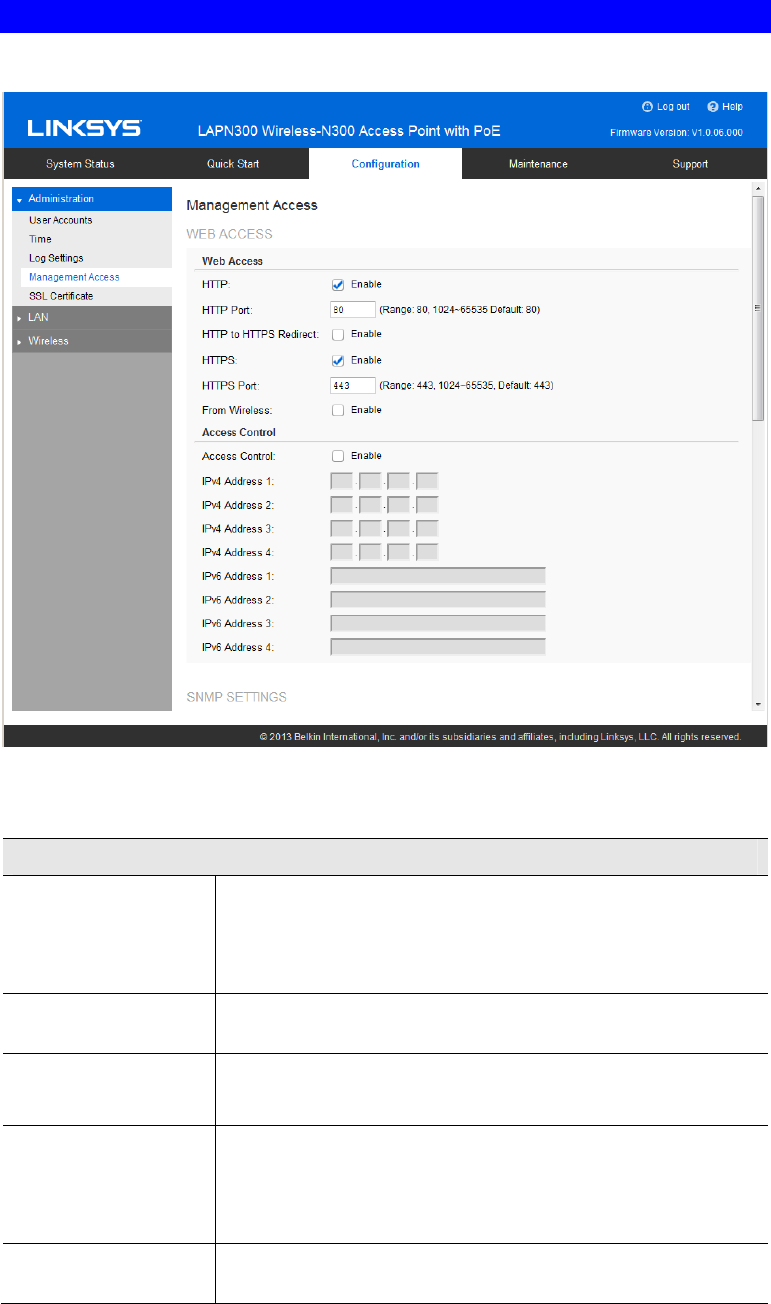
Management Access Screen
You can use the Management page to configure the management methods of the access point.
Figure 12: Management Access Screen
Data - Management Access Screen
Web Access
HTTP HTTP (Hyper Text Transfer Protocol) is the standard for
transferring files (text, graphic images and other multimedia files)
on the World Wide Web.
Enable to allow Web access by HTTP protocol.
HTTP Port Specify the port for HTTP. It can be 80 (default) or from 1024 to
65535.
HTTP to HTTPS
Redirect Enable to redirect Web access of HTTP to HTTPS automatically.
This field is available only when HTTP access is disabled.
HTTPS HTTPS (Hypertext Transfer Protocol Secure) can provide more
secure communication with the SSL/TLS protocol, which support
data encryption to HTTP clients and servers.
Enable to allow Web access by HTTPS protocol.
HTTPS Port Specify the port for HTTPS. It can be 443 (default) or from 1024
to 65535.

15
From Wireless Enable wireless devices to connect to access point’s admin page.
Disabled by default.
Access Control By default, no IP addresses are prohibited from accessing the
device’s admin page. You can enable access control and enter
specified IP addresses for access. Four IPv4 and four IPv6 ad-
dresses can be specified.
SNMP Settings
SNMP Simple Network Management Protocol (SNMP) is a network
monitoring and management protocol.
Enable or disable SNMP function here. Disabled by default.
Contact Enter contact information for the access point.
The contact includes 1 to 32 characters. Special characters are
allowed.
Location Enter the area or location where the access point resides.
The location includes 1 to 32 characters. Special characters are
allowed.
SNMP v1/v2 Settings
Get Community Enter the name of Get Community. Get Community is used to
read data from the access point and not for writing data into the
access point.
Get Community includes 1 to 32 characters. Special characters
are allowed.
Set Community Enter the name of Set Community. Set Community is used to
write data into the access point.
The Set Community includes 1 to 32 characters. Special charac-
ters are allowed.
SNMP v3 Settings
SNMP v3 Settings Configure the SNMPv3 settings if you want to use SNMPv3.
• Username: Enter the username. It includes 0 to 32 charac-
ters. Special characters are allowed.
• Authentication Protocol: None or HMAC-MD5.
• Authentication Key: 8 to 32 characters. Special characters
are allowed.
• Privacy Protocol: None or CBC-DES.
• Privacy Key: 8 to 32 characters. Special characters are
allowed.
Access Control
Access Control When SNMP is enabled, any IP address can connect to the access
point’s admin page through SNMP. You can enable access
control to allow specified IP addresses. Two IPv4 and two IPv6
addresses can be specified.
SNMP Trap

16
Trap Community Enter the Trap Community server. It includes 1 to 32 characters.
Special characters are allowed.
Trap Destination Two Trap Community servers are supported: can be IPv4 or
IPv6.
17
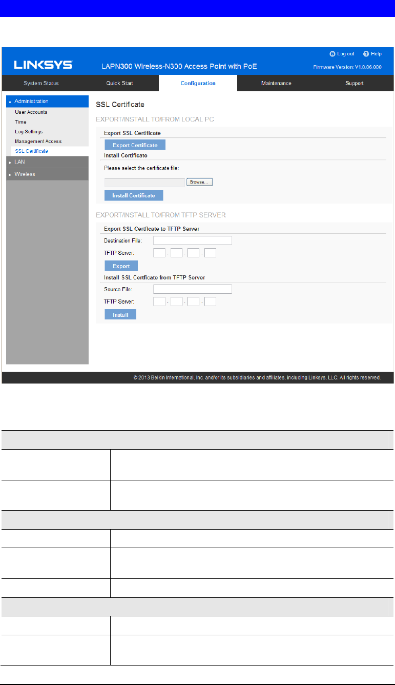
SSL Certificate Screen
This screen can be used to manage SSL certificate used by HTTPS.
Figure 13: SSL Certificate Screen
Data - SSL Certificate Screen
Export/Restore to/from Local PC
Export SSL
Certificate Click to export the SSL certificate.
Install Certificate Browse to choose the certificate file. Click Install Certificate
button.
Export to TFTP Server
Destination File Enter the name of the destination file.
TFTP Server Enter the IP address for the TFTP server. Only support IPv4
address here.
Export Click to export the SSL certificate to the TFTP server.
Restore from TFTP Server
Source File Enter the name of the source file.
TFTP Server Enter the IP address for the TFTP server. Only support IPv4
address here.

18
Install Click to install the file to the device.
19
Network Setup Screen
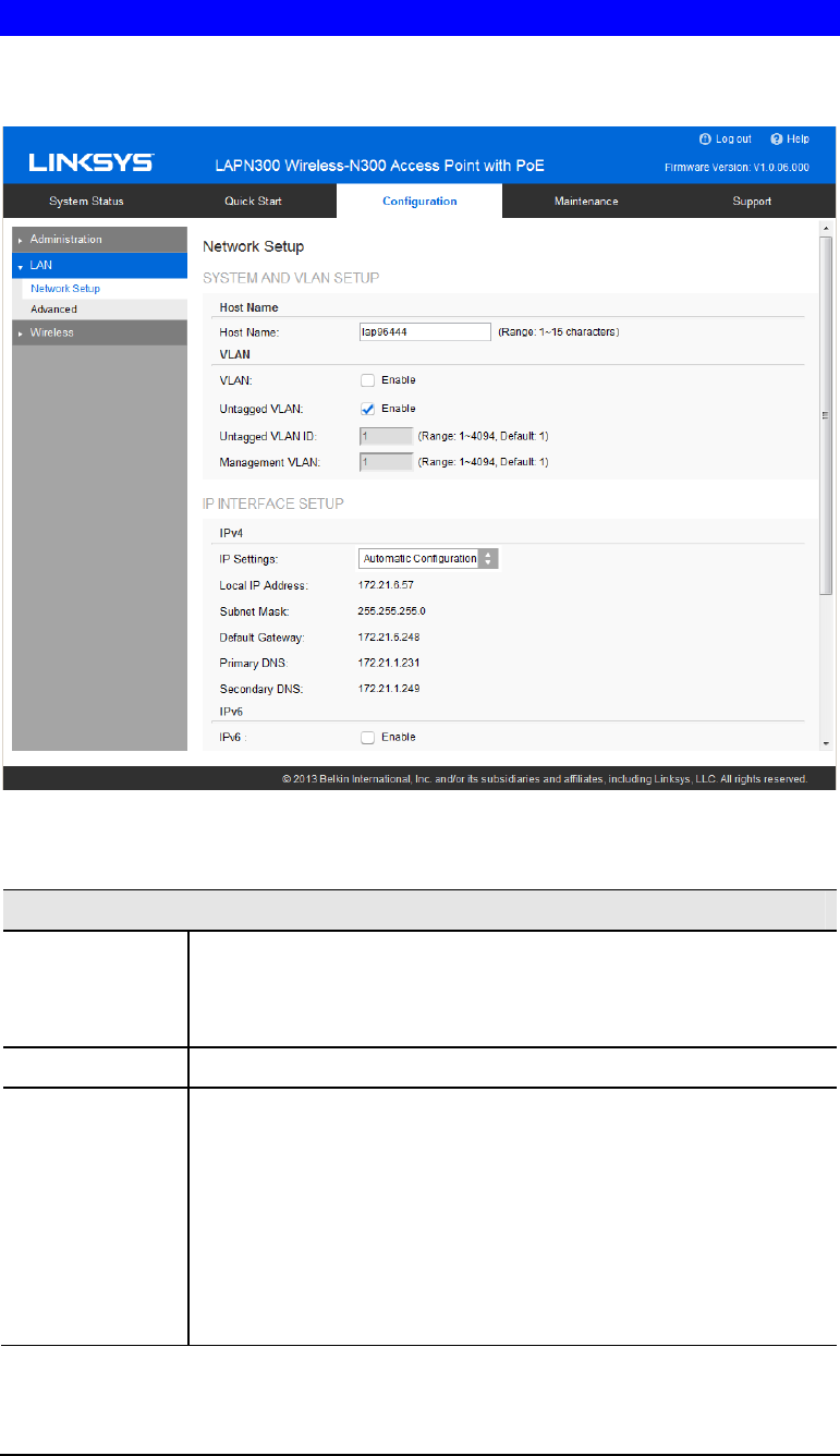
Use this screen to configure basic device settings, VLAN settings and settings for the LAN
interface, including static or dynamic IPv4/IPv6 address assignment.
Figure 14: Network Setup Screen
Data - Network Setup Screen
TCP/IP
Host Name Assign a host name to this access point. Host name consists of 1 to 15
characters. Valid characters include A-Z, a-z, 0-9 and -. Character
cannot be first and last character of hostname and hostname cannot be
composed of all digits.
VLAN Enables or disables VLAN function.
Untagged VLAN Enables or disables VLAN tagging. If enabled (default), traffic from
the LAN port is untagged when the following conditions are met: 1)
VLAN ID is equal to Untagged VLAN ID and 2) untagged traffic can
be accepted by LAN port. If disabled, traffic from the LAN port is
always tagged and only tagged traffic can be accepted from LAN port.
By default all traffic on the access point uses VLAN 1, the default
untagged VLAN. All traffic will be untagged until you disable the
untagged VLAN, change the untagged traffic VLAN ID, or change the
VLAN ID for a SSID.

20
Untagged VLAN
ID Specifies a number between 1 and 4094 for the untagged VLAN ID.
The default is 1. Traffic on the VLAN that you specify in this field is
not be tagged with a VLAN ID when forwarded to the network.
Untagged VLAN ID field is active only when untagged VLAN is
enabled.
VLAN 1 is the default for both untagged VLAN and management
VLAN.
Management
VLAN The VLAN associated with the IP address you use to connect to the
access point. Provide a number between 1 and 4094 for the Manage-
ment VLAN ID. The default is 1.
IPv4/v6
IP Settings Select Automatic Configuration or Static IP Address.
IP Address Enter an unused IP address from the address range used on your LAN.
Subnet Mask Enter the subnet mask for the IP address above.
Default Gateway Enter the gateway for the IP address above.
Primary DNS Enter the DNS address.
Secondary DNS Optional. If entered, this DNS will be used if the Primary DNS does
not respond.
21
Advanced Screen
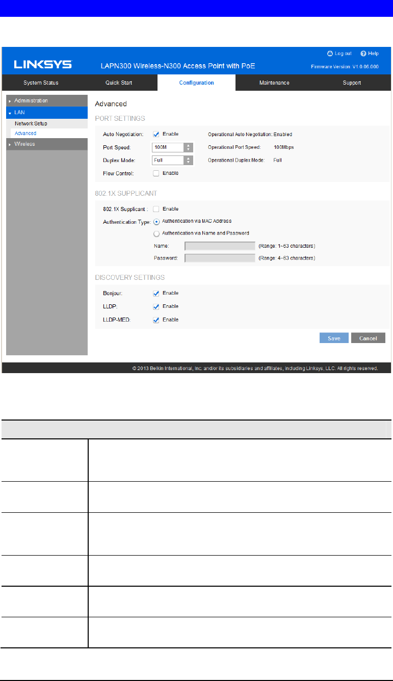
Use this screen to configure advanced network settings of the access point.
Figure 15: Advanced Screen
Data - Advanced Screen
Port Settings
Auto Negotiation If enabled, Port Speed and Duplex Mode will become grey and cannot
be configured. If disabled, Port Speed and Duplex Mode can be
configured.
Operational
Auto Negotiation Current Auto Negotiation mode of the Ethernet port.
Port Speed Select the speed of the Ethernet port. Available only when Auto
Negotiation is disabled. The option can be 10M, 100M or 1000M
(default).
Operational Port
Speed Displays the current port speed of the Ethernet port.
Duplex Mode Select the duplex mode of the Ethernet port. Available only when Auto
Negotiation is disabled. The option can be Half or Full (default).
Operational
Duplex Mode Displays the current duplex mode of the Ethernet port.

22
Flow Control Enable or disable flow control of the Ethernet port.
802.1x Supplicant
802.1x
Supplicant Enable if your network requires this access point to use 802.1X
authentication in order to operate.
Authentication This feature supports following two kinds of authentication:
• Authentication via MAC Address
Select this if you want to use MAC Address for authentica-
tion.
The access point uses lowercase MAC address for Name and
Password, like xxxxxxxxxxxx.
• Authentication via Name and Password
Select this if you want to use name and password for
authentication.
Name - Enter the login name. The name includes 1 to 63
characters. Special characters are allowed.
Password - Enter the desired login password. The password
includes 4 to 63 characters. Special characters are allowed.
Discovery Settings
Bonjour Enable if administrator wants the access point to be discovered by
Bonjour enabled devices automatically. If VLAN is enabled, the
discovery packets will be sent out via management VLAN only. The
access point supports http and https services.
LLDP Enable if administrator wants the access point to be discovered by
switch by LLDP protocol. Information such as product name, device
name, firmware version, IP address, MAC address and so on will be
advertised.
LLDP-MED Enable if administrator wants the access point to be discovered by
switch by LLDP-MED protocol. Information such as product name,
device name, firmware version, IP address, MAC address and so on
will be advertised.
23
Wireless Screens
There are ten configuration screens:
• Basic Settings
• Security
• Rogue AP Detection
• Scheduler
• Scheduler Association
• Connection Control
• Rate Limit
• QoS
• Workgroup Bridge
• Advanced Settings
Basic Settings
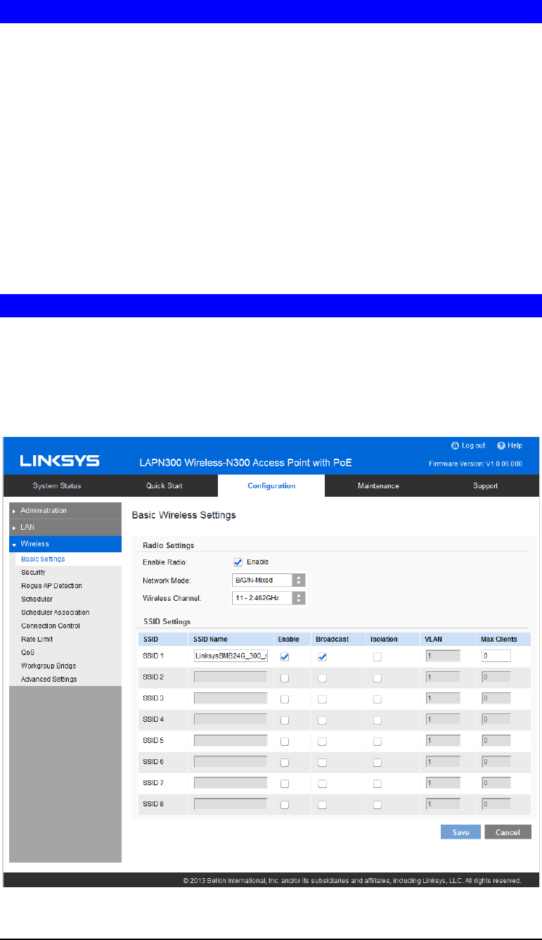
Basic Settings provides the essential configuration for your wireless radio and SSIDs. You
should able to set up your wireless network with these essential parameters configured. For
advanced wireless settings such as Band Steering, Channel Bandwidth etc., they will be on
Configuration ÆWirelessÆ Advanced Settings screen.
Click Basic Settings on the Wireless menu.
Figure 16: Basic Settings Screen

24
Data - Wireless Basic Settings Screen
Basic Wireless Settings
Enable Radio Enable or disable the wireless radio.
Wireless Mode Select the desired option:
• G only - allow connection by 802.11G wireless stations only.
• N only - allow connection by 802.11N wireless stations only.
• B/G-Mixed - allow connection by 802.11B and G wireless
stations only.
• B/G/N-Mixed (Default) - allow connections by 802.11N,
802.11B and 802.11G wireless stations.
Wireless Channel Select wireless channel of the radio.
If Auto is selected, the access point will select the best available
channel when device boots up.
If you experience lost connections and/or slow data transfers,
experiment with manually setting different channels to see which is the
best.
SSID Settings
SSID Name Enter the desired SSID Name. Each SSID must have a unique name.
The name includes 1 to 32 characters
Broadcast Enable or disable the broadcast of the SSID.
When the access point does not broadcast its SSID, the network name
is not shown in the list of available networks on a client station. In-
stead, you must enter the exact network name manually into the
wireless connection utility on the client so that it can connect.
Isolation Enable or disable isolation among clients of the SSID. If enabled,
wireless clients cannot communicate with others in the same SSID.
It’s disabled by default.
VLAN ID Enter the VLAN ID of the SSID.
Used to tag packets which are received from the wireless clients of the
SSID and sent from Ethernet or Workgroup Bridge interfaces.
Applicable only when VLAN function is enabled. VLAN function can
be configured in Configuration -> LAN -> Network Setup screen.
Max Clients Enter the number of clients that can connect to the SSID. The range is
from 0 to 32, and 0 means no limit.
25
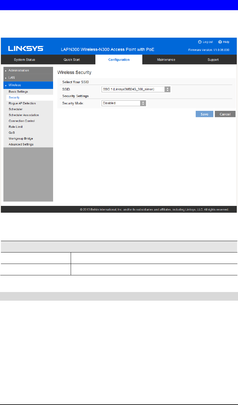
Security Settings
Use this screen to configure security settings of SSIDs to provide data protection over the
wireless network
Figure 17: Security Settings
Data - SSID Settings Screen
Security
Select SSID Select the desired SSID from the drop-down list.
Security Mode Select the desired security method from the list.
Security Settings
• Disabled - No security. Anyone using the correct SSID can connect to your network.
• WEP - The 802.11b standard. Data is encrypted before transmission, but the encryption
system is not very strong.
• WPA2-Personal - This is a further development of WPA-PSK, and offers even greater
security, using the AES (Advanced Encryption Standard) method. This method, some-
times called "Mixed Mode", allows clients to use either WPA-Personal (with TKIP) or
WPA2-Personal (with AES).
• WPA2-Enterprise - Requires a RADIUS Server on your LAN to provide the client
authentication according to the 802.1x standard. Data transmissions are encrypted using
the WPA2 standard.
If this option is selected:
26
• This access point must have a client login on the RADIUS Server.
• Each user must authenticate on the RADIUS Server. This is usually done using digital
certificates.
• Each user's wireless client must support 802.1x and provide the RADIUS authentica-
tion data when required.
• All data transmission is encrypted using the WPA2 standard. Keys are automatically
generated, so no key input is required.
• RADIUS - RADIUS mode utilizes RADIUS server for authentication and dynamic WEP
key generation for data encryption.
27
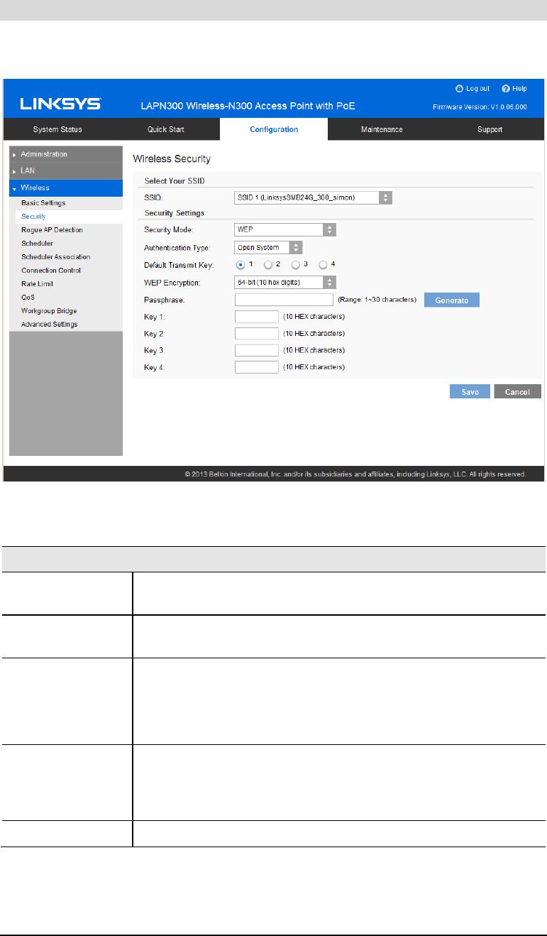
Security Settings - WEP
This is the 802.11b standard. Data is encrypted before transmission, but the encryption system
is not very strong.
Figure 18: WEP Wireless Security Screen
Data - WEP Screen
WEP
Authentication Select Open System or Shared Key. All wireless stations must use the
same method.
Default Transmit
Key Select a transmit key.
WEP Encryption Select an encryption option, and ensure your wireless stations have
the same setting:
• 64-Bit Encryption - Keys are 10 Hex characters.
• 128-Bit Encryption - Keys are 26 Hex characters.
Passphrase Generate a key or keys, instead of entering them directly. Enter a
word or group of printable characters in the Passphrase box and click
the Generate button to automatically configure the WEP key. It
consists of 1 to 30 characters.
Key Value Enter a key in hexadecimal format.
28
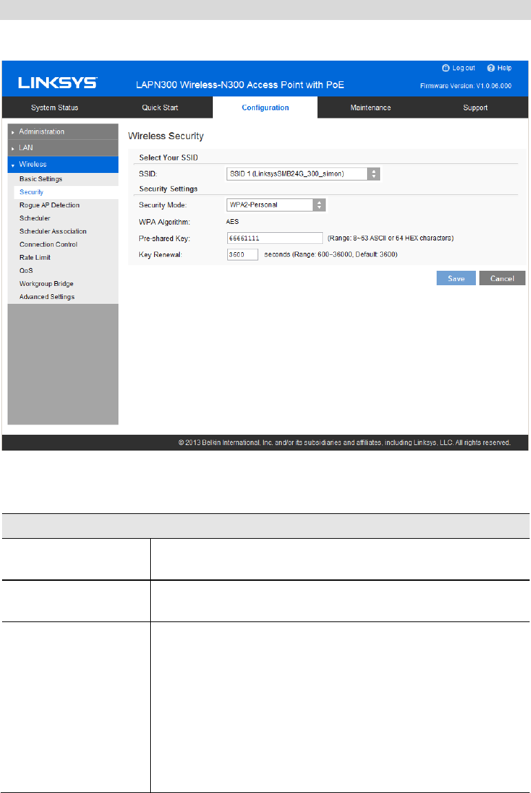
Security Settings - WPA2-Personal
This is a further development of WPA-Personal, and offers even greater security.
Figure 19: WPA2-Personal Wireless Security Screen
Data - WPA2-Personal Screen
WPA2-Personal
WPA Algorithm The encryption method is AES. Wireless stations must also use
AES.
Pre-shared Key Enter the key value. It is 8 to 63 ASCII characters or 64 HEX
characters. Other wireless stations must use the same key.
Key Renewal Specify the value of Group Key Renewal. It’s a value from 600
to 36000 and default is 3600.
WPA automatically changes secret keys after a certain period of
time. The group key interval is the period of time in between
automatic changes of the group key, which all devices on the
network share.
Constantly keying the group key protects your network against
intrusion, as the would-be intruder must cope with an ever-
changing secret key.
29
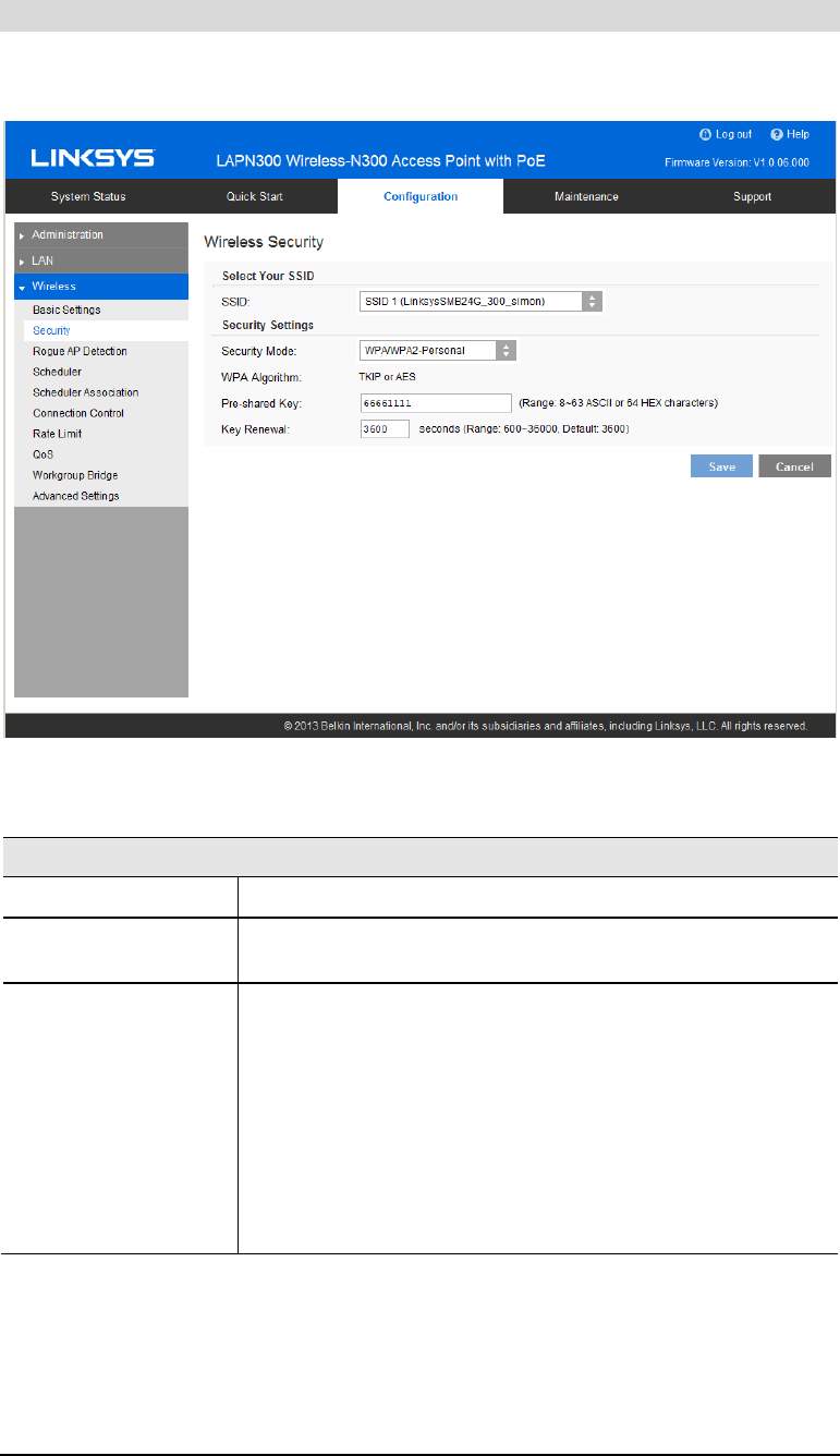
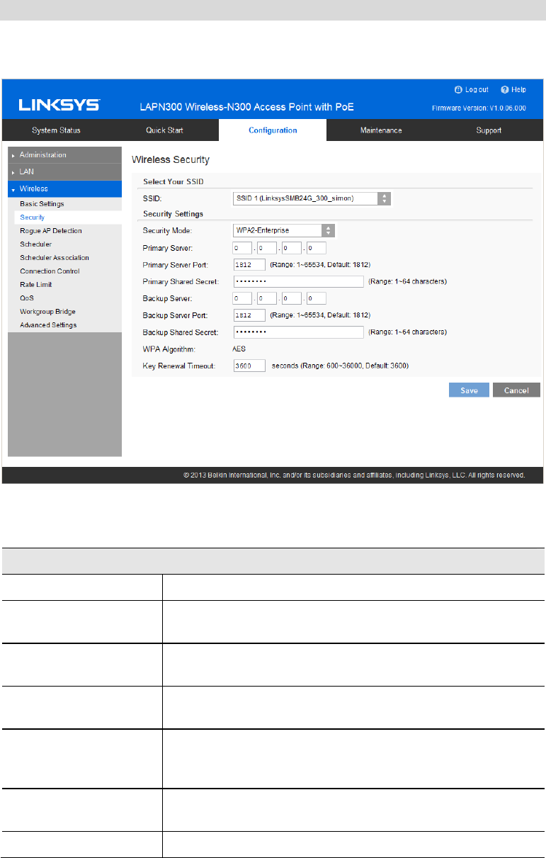
Security Settings - WPA/WPA2-Personal
This method, sometimes called Mixed Mode, allows clients to use either WPA-Personal or
WPA2-Personal.
Figure 20: WPA/WPA2-Personal Wireless Security Screen
Data - WPA/WPA2-Personal Screen
WPA/WPA2-Personal
WPA Algorithm The encryption method is TKIP or AES.
Pre-shared Key Enter the key value. It is 8 to 63 ASCII characters or 64 HEX
characters. Other wireless stations must use the same key.
Key Renewal Specify the value of Group Key Renewal. It’s a value from 600
to 36000, and default is 3600.
WPA automatically changes secret keys after a certain period of
time. The group key interval is the period of time in between
automatic changes of the group key, which all devices on the
network share.
Constantly keying the group key protects your network against
intrusion, as the would-be intruder must cope with an ever-
changing secret key.
30
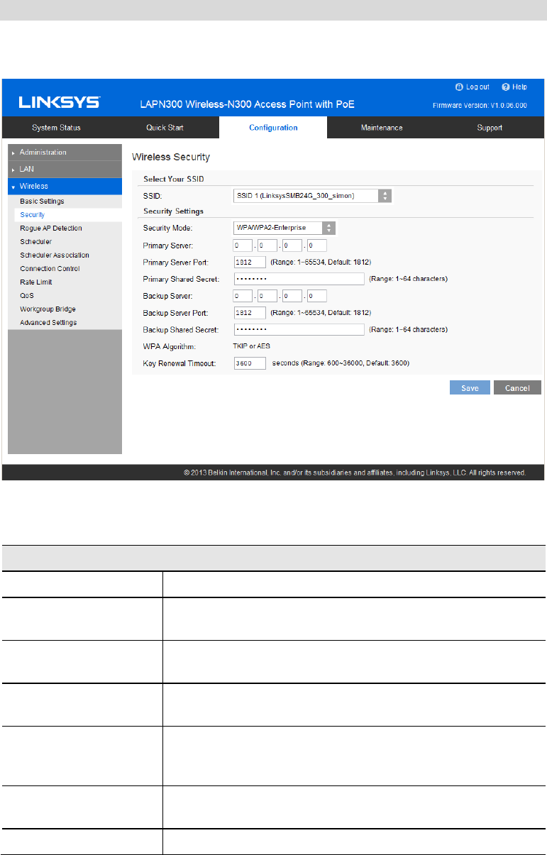
Security Settings - WPA2-Enterprise
This version of WPA2-Enterprise requires a RADIUS Server on your LAN to provide the
client authentication. Data transmissions are encrypted using the WPA2 standard.
Figure 21: WPA2-Enterprise Wireless Security Screen
Data - WPA2-Enterprise Screen
WPA2-Enterprise
Primary Server Enter the IP address of the RADIUS Server on your network.
Primary Server Port Enter the port number used for connections to the RADIUS
Server. It is a value from 1 to 65534, and default is 1812.
Primary Shared Secret Enter the key value to match the RADIUS Server. It consists of
1 to 64 characters.
Backup Server The Backup Authentication Server will be used when the
Primary Authentication Server is not available.
Backup Server Port Enter the port number used for connections to the Backup
RADIUS Server. It’s a value from 1 to 65534, and default is
1812.
Backup Shared Secret Enter the key value to match the Backup RADIUS Server. It
consists of 1 to 64 characters.
WPA Algorithm The encryption method is AES.

31
Key Renewal Timeout Specify the value of Group Key Renewal. It is a value from 600
to 36000, and default is 3600.
WPA automatically changes secret keys after a certain period of
time. The group key interval is the period of time in between
automatic changes of the group key, which all devices on the
network share.
Constantly keying the group key protects your network against
intrusion, as the would-be intruder must cope with an ever-
changing secret key.
32
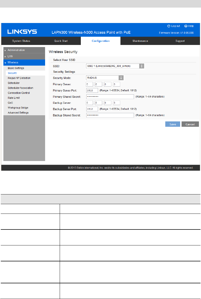
Security Settings - WPA/WPA2-Enterprise
WPA/WPA2-Enterprise requires a RADIUS Server on your LAN to provide the client authen-
tication. Data transmissions are encrypted using WPA2 standard.
Figure 22: WPA/WPA2-Enterprise Wireless Security Screen
Data - WPA/WPA2-Enterprise Screen
WPA/WPA2-Enterprise
Primary Server Enter the IP address of the RADIUS Server on your network.
Primary Server Port Enter the port number used for connections to the RADIUS
Server. It is a value from 1 to 65534, and default is 1812.
Primary Shared Secret Enter the key value to match the RADIUS Server. It consists of
1 to 64 characters.
Backup Server The Backup Authentication Server will be used when the
Primary Authentication Server is not available.
Backup Server Port Enter the port number used for connections to the Backup
RADIUS Server. It is a value from 1 to 65534, and default is
1812.
Backup Shared Secret Enter the key value to match the Backup RADIUS Server. It
consists of 1 to 64 characters.
WPA Algorithm The encryption method is TKIP or AES.

33
Key Renewal Timeout Specify the value of Group Key Renewal. It is a value from 600
to 36000, and default is 3600.
WPA automatically changes secret keys after a certain period of
time. The group key interval is the period of time between
automatic changes of the group key, which all devices on the
network share.
Constantly keying the group key protects your network against
intrusion, as the would-be intruder must cope with an ever-
changing secret key.
34
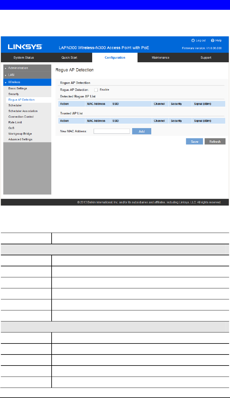
RADIUS
Use RADIUS server for authentication and dynamic WEP key generation for data encryption.
Figure 23: RADIUS Settings
Data - RADIUS Screen
Authentication Server
Primary Server Enter the IP address of the RADIUS Server on your network.
Primary Server Port Enter the port number used for connections to the RADIUS
Server. It is a value from 1 to 65534, and default is 1812.
Primary Shared Secret Enter the key value to match the RADIUS Server. It consists of
1 to 64 characters.
Backup Server The Backup Authentication Server will be used when the
Primary Authentication Server is not available.
Backup Server Port Enter the port number used for connections to the Backup
RADIUS Server. It is a value from 1 to 65534, and default is
1812.
Backup Shared Secret Enter the key value to match the Backup RADIUS Server. It
consists of 1 to 64 characters.
35
Rogue AP Detection
Rogue AP detection is used to detect the unexpected or unauthorized access point installed in a
secure network environment.
Figure 24: Rogue AP Screen
Data - Rogue AP Screen
Rogue AP Enable or disable Rogue AP Detection on the selected radio.
Detected Rogue AP List
Action Click Trust to move the AP to the Trusted AP List.
MAC Address The MAC address of the Rogue AP.
SSID The SSID of the Rogue AP.
Channel The channel of the Rogue AP.
Security The security method of the Rogue AP.
Signal The signal level of the Rogue AP.
Trusted AP List
Action Click Untrust to move the AP to the Rogue AP List.
MAC Address The MAC address of the Trusted AP.
SSID The SSID of the Trusted AP.
Channel The channel of the Trusted AP.
Security The security method of the Trusted AP.

36
Signal The signal level of the Trusted AP.
New MAC
Address Add one trusted AP by MAC address.
37
Scheduler
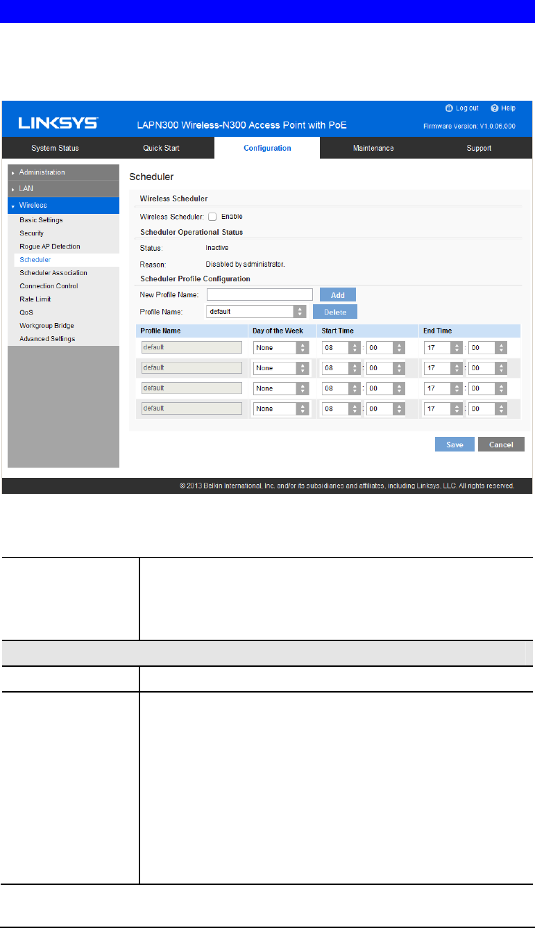
Configure a rule with a specific time interval for SSIDs to be operational. Automate enabling
or disabling SSIDs based on the profile definition. Support up to 16 profiles and each profile
can include 4 time rules.
Figure 25: Scheduler Screen
Data - Scheduler Screen
Wireless Scheduler Enable or disable wireless scheduler on the radio. It is disabled by
default.
If disabled, even if some SSIDs are associated with profiles, they
will be always active.
Scheduler Operational Status
Status The operational status of the scheduler.
Reason The detailed reason for the scheduler operational status. It includes
following situations.
• System time is outdated.
Scheduler is inactive because system time is outdated.
• Administrative Mode is disabled.
Scheduler is disabled by administrator.
• Active
Scheduler is active.

38
Scheduler Profile configuration
New Profile Name Enter the name for new profile.
Profile Name Select the desired profile from the list to configure.
Day of the Week Select the desired day from the list.
Option None means this time rule is disabled.
Start Time Choose the start time.
Finish Time Choose the finish time.
39
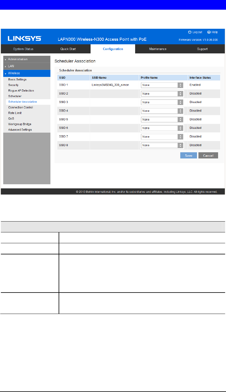
Scheduler Association
Associate defined scheduler profiles with SSIDs.
Figure 26: Scheduler Association Screen
Data - Scheduler Association Screen
Scheduler Association
SSID The index of SSID.
SSID Name The name of the SSID.
Profile Name Choose the profile that is associated with the SSID.
If the profile associated with the SSID is deleted, then the associa-
tion will be removed.
If "None" is selected, it means no scheduler profile is associated.
Interface Status The Status of the SSID. It can be Enabled or Disabled.
Scheduler only works when the SSID is enabled.
40
Connection Control
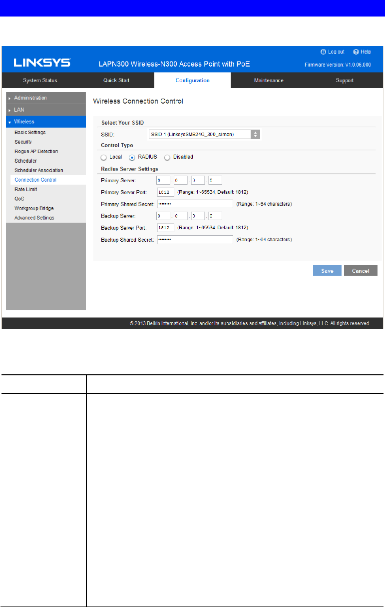
Exclude or allow only listed client stations to authenticate with the access point.
Figure 27: Connection Control Screen
Data - Connection Control Screen
SSID Select the desired SSID from the list.
Connection Type Select the option from the drop-down list as desired.
• Local: Choose either Allow only following MAC addresses to
connect to wireless network or Prevent following MAC addresses
from connection to wireless network. You can enter up to 20
MAC addresses of wireless stations or choose the MAC
address.
• RADIUS
• Primary/Backup RADIUS Server - Enter the IP address of the
RADIUS Server.
• Primary/Backup RADIUS Server Port – Enter the Port
number of the RADIUS Server.
• Primary/Backup Shared Secret - This is shared between the
wireless access point and the RADIUS Server while
authenticating the device attempting to connect.
• Disabled
41
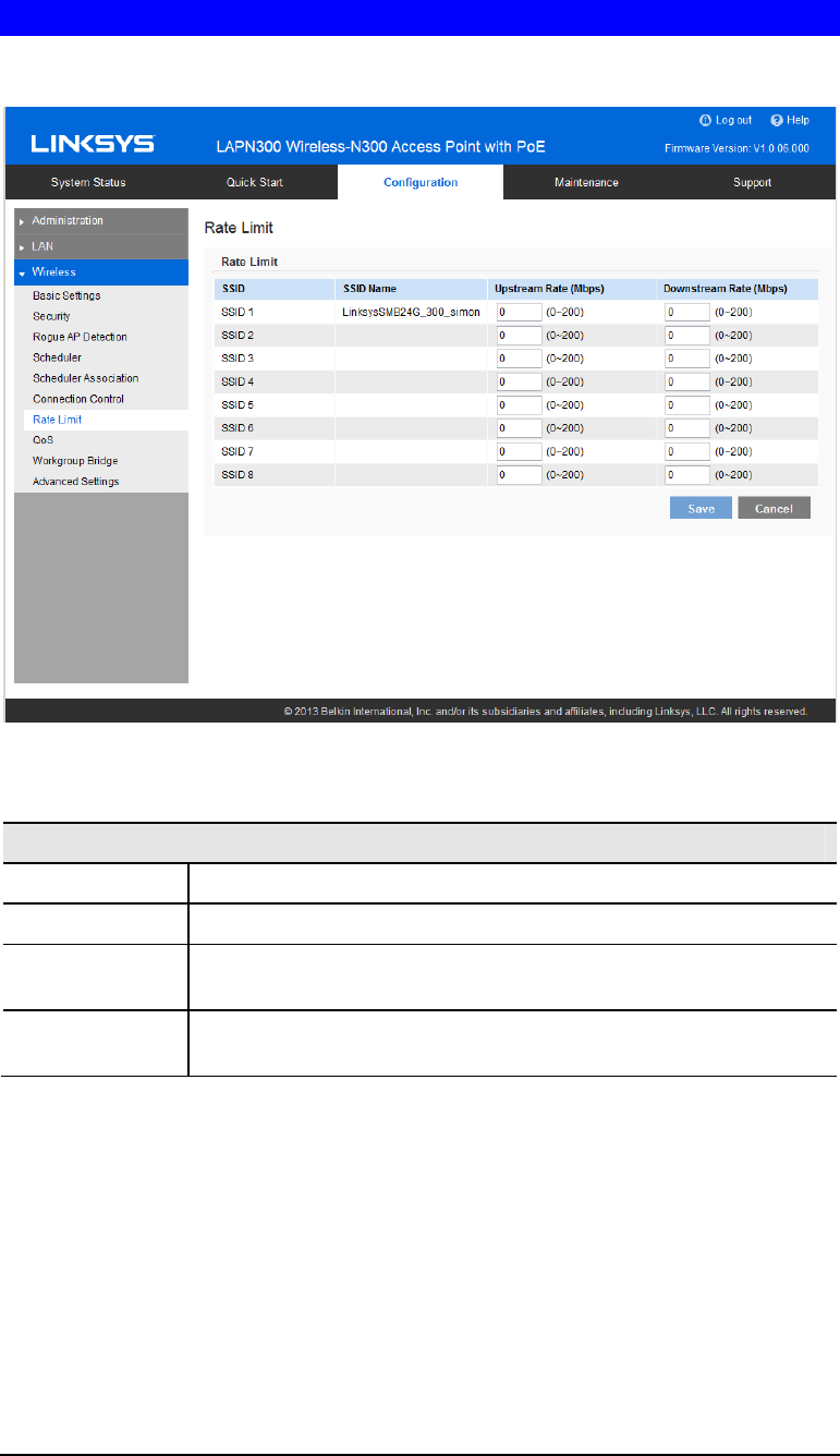
Rate Limit
Limit downstream and upstream rate of SSIDs.
Figure 28: Rate Limit Screen
Data - Rate Limit Screen
Rate Limit
SSID The index of SSID.
SSID Name The name of the SSID.
Upstream Rate Enter a maximum upstream for the SSID. The range is from 0 to 200
Mbps; 0 means no limitation.
Downstream
Rate Enter a maximum downstream for the SSID. The range is from 0 to
200 Mbps; 0 means no limitation.
42
QoS
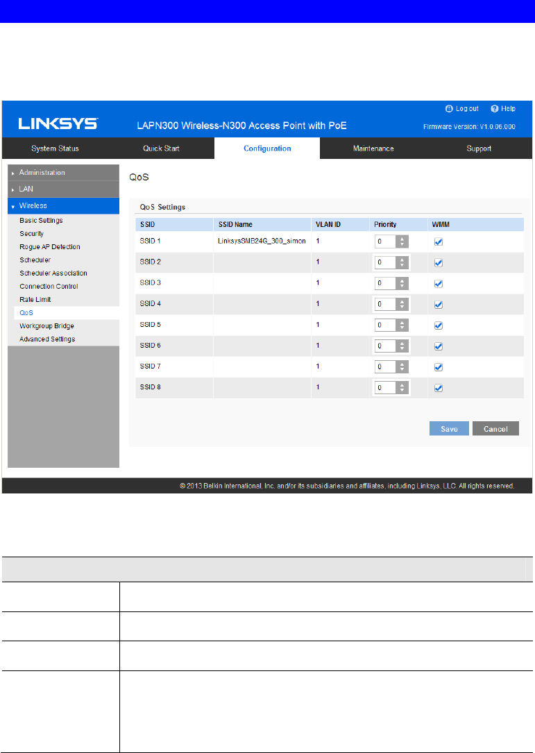
The QoS (Quality of Service) feature allows you to specify priorities for different traffic
coming from your wireless client. Lower priority traffic will be slowed down to allow greater
throughput or less delay for high priority traffic.
Figure 29: QoS Screen
Data - QoS Screen
QoS Setting
SSID The index of SSID.
SSID Name The name of the SSID.
VLAN ID The VLAN ID of the SSID.
Priority Select the priority level from the list.
The 802.1p will be included in the VLAN header of the packets which
are received from the SSID and sent from Ethernet or Workgroup
Bridge interface.

43
WMM Enable or disable WMM.
WMM (Wi-Fi Multimedia) is a component of the IEEE 802.11e
wireless LAN standard for QoS.
WMM provides prioritization of wireless data packets from different
applications based on four access categories: voice, video, best effort,
and background. For an application to receive the benefits of WMM
QoS, both it and the client running that application have to have WMM
enabled. Legacy applications that do not support WMM and applica-
tions that do not require QoS, are assigned to the best effort category,
which receives a lower priority than voice and video.
WMM is enabled by default.
44
Workgroup Bridge
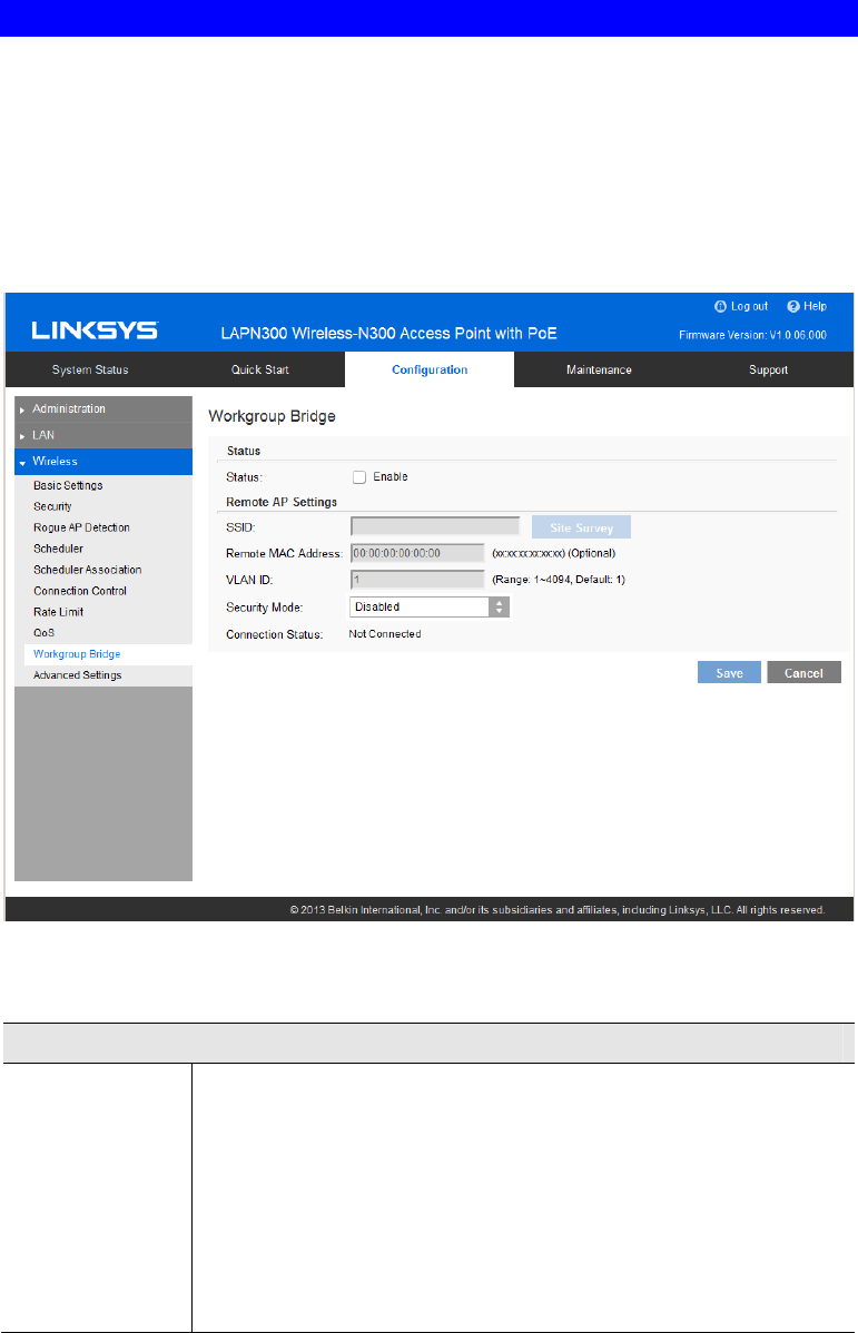
Workgroup Bridge feature enables the access point to extend the accessibility of a remote network.
In Workgroup Bridge mode, the access point acts as a wireless station (STA) on the wireless LAN. It
can bridge traffic between a remote wired network and a wireless LAN.
When Workgroup Bridge is enabled, SSID configuration still works to provide wireless
services to clients.
All access points participating in Workgroup Bridge must have the identical settings for Radio
interface, IEEE 802.11 mode, Channel Bandwidth, Channel (Auto is not recommended).
Figure 30: Workgroup Bridge
Data - Workgroup Bridge Screen
Workgroup Bridge Status
Status Enable or disable Workgroup Bridge function.
Before configuring Workgroup Bridge, make sure all devices in
Workgroup Bridge have the following identical settings.
• Radio
• IEEE 802.11 Mode
• Channel Bandwidth
• Channel (Auto is not recommended)

45
Infrastructure Client Interface
SSID Enter the name of the SSID to which Workgroup Bridge will connect.
Click Site Survey button to choose from the list. It's necessary for
Workgroup Bridge to connect to remote access point.
Remote MAC
Address
Normally, Workgroup Bridge connects to a remote access point by
matching SSID. When more than one remote access point have the
same SSID, Workgroup Bridge can connect to different remote access
points.
Optional: You can specify the MAC address of the remote access point
to limit Workgroup Bridge’s connection to a specific remote access
point.
The format is xx:xx:xx:xx:xx:xx.
VLAN ID Enter the VLAN ID for Workgroup Bridge.
When VLAN function is enabled, Workgroup Bridge only forwards
packets with specified VLAN to remote access points.
The list is only applicable when VLAN function is enabled.
Security Mode Select the desired mode from the list.
• Disabled
• WPA-Personal
• WPA2-Personal
46
Advanced Settings
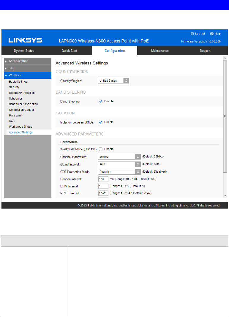
Configure advanced parameters of the wireless radio.
Figure 31: Advanced Settings
Data - Advanced Settings Screen
Country/Region
Country/Region Select your country or region from the drop-down list. This
field displays the region of operation for which the wireless
interface is intended. It may not be legal to operate the access
point in a country/region not shown here. If your country or
region is not listed, please check with your local government
agency or Linksys’s website for more information on which
channels to use.
Note: The country code function is for non-US model
only and all US-models does not have this function.

47
Band Steering
Band Steering Enable or disable Band Steering function.
Band Steering is a technology that detects whether the wireless
client is dual-band capable. If it is, band steering pushes the
client to connect to the less-congested 5 GHz network. It does
this by actively blocking the client’s attempts to connect with
the 2.4GHz network.
Isolation
Isolation between
SSIDs Define whether to isolate traffic between SSIDs. If enabled,
wireless clients in different SSIDs cannot communicate with
each other. Enabled by default.
Advanced Parameters
Worldwide Mode
(802.11d) Worldwide Mode (802.11d) enables the access point to direct
connected wireless devices to radio settings specific to where in
the world the devices are in use.
Channel Bandwidth You can select the channel bandwidth manually for Wireless-N
connections. When it is set to 20MHz, only 20MHz channel is
being used. When it is set to 40MHz, Wireless-N connections
will use 40MHz channel, but Wireless-B connections and
Wireless-G connections will still use 20MHz channel.
Guard Interval Select the guard interval manually for Wireless-N connections.
The two options are Short (400 nanoseconds) and Long (800
nanoseconds). The default is Auto.
CTS Protection Mode CTS (Clear-To-Send) Protection Mode boosts the access point's
ability to catch all Wireless-G transmissions, but it severely
decreases performance. By default, CTS Protection Mode is
disabled, but the access point will automatically enable this
feature when Wireless-G devices are not able to transmit to the
access point in an environment with heavy 802.11b traffic.
Beacon Interval The access point transmits beacon frames at regular intervals to
announce the existence of the wireless network. Enter the
interval between the transmissions of beacon frames. The value
range is between 40 and 1000 milliseconds and default is 100
milliseconds.
DTIM Interval Enter the Delivery Traffic Information Map (DTIM) period, an
integer from 1 to 255 beacons. The default is 1 beacon.
The DTIM message is an element included in some beacon
frames. It indicates which client stations, currently sleeping in
low-power mode, have data buffered on the access point await-
ing pickup.
The DTIM period that you specify indicates how often the
clients served by this WAP device should check for buffered
data still on the access point awaiting pickup.
For example, if you enter 1, clients check for buffered data on
the access point at every beacon. If you enter 10, clients check
on every 10th beacon.

48
RTS Threshold Enter the Request to Send (RTS) Threshold value, an integer
from 1 to 2347. The default is 2347 octets.
The RTS threshold indicates the number of octets in a Medium
Access Control Protocol Data Unit (MPDU) below which an
RTS/CTS handshake is not performed.
Changing the RTS threshold can help control traffic flow
through the access point, especially one with a lot of clients. If
you specify a low threshold value, RTS packets are sent more
frequently, which consumes more bandwidth and reduces the
throughput of the packet. However, sending more RTS packets
can help the network recover from interference or collisions that
might occur on a busy network, or on a network experiencing
electromagnetic interference.
Fragmentation
Threshold Enter the fragmentation threshold, an integer from 256 to 2346.
The default is 2346.
The fragmentation threshold is a way of limiting the size of
packets (frames) transmitted over the network. If a packet
exceeds the fragmentation threshold you set, the fragmentation
function is activated and the packet is sent as multiple 802.11
frames.
If the packet being transmitted is equal to or less than the
threshold, fragmentation is not used. Setting the threshold to the
largest value (2,346 bytes, which is the default) effectively
disables fragmentation.
Fragmentation involves more overhead because of the extra
work of dividing up and reassembling of frames it requires, and
because it increases message traffic on the network. However,
fragmentation can help improve network performance and
reliability if properly configured.
Output Power Select the output power of the access point. If many access
points exist, lower power can reduce the signal interference
among them.
49
Chapter 3
Operation and Status
Operation
You may need to perform the following operations on a regular basis.
• If using the Access Control feature, update the Trusted PC database as required. (See
Access Control in Chapter 2 for details.)
• If using 802.1x mode, update the User Login data on the Windows 2000 Server, and
configure the client PCs, as required.
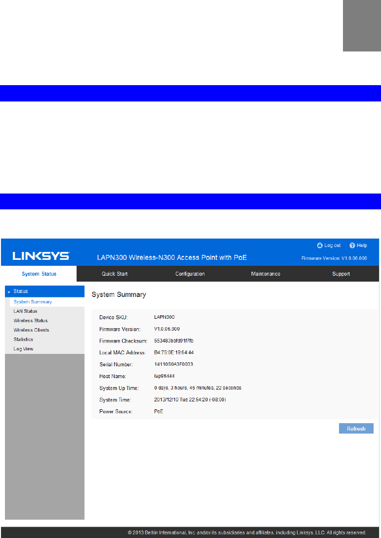
System Summary
Provides system status of the access point.
Figure 32: System Summary Screen
3

50
Data - System Summary Screen
System Summary
Device SKU The SKU is often used to identify device model number and
region.
Firmware Version The version of the firmware currently installed.
Firmware Checksum The checksum of the firmware running in the access point.
Local MAC Address The MAC (physical) address of the wireless access point.
Serial Number The serial number of the device.
Host Name The host name assigned to the access point.
System Up Time How long the system has been running since the last restart or
reboot.
System Time The current date and time.
Power Source The power source of the access point. It can be Power over
Ethernet (PoE) or Power Adapter. When two power sources are
plugged in, Power Adaptor will be displayed.
Buttons
Refresh Click to update the data on the screen.
51
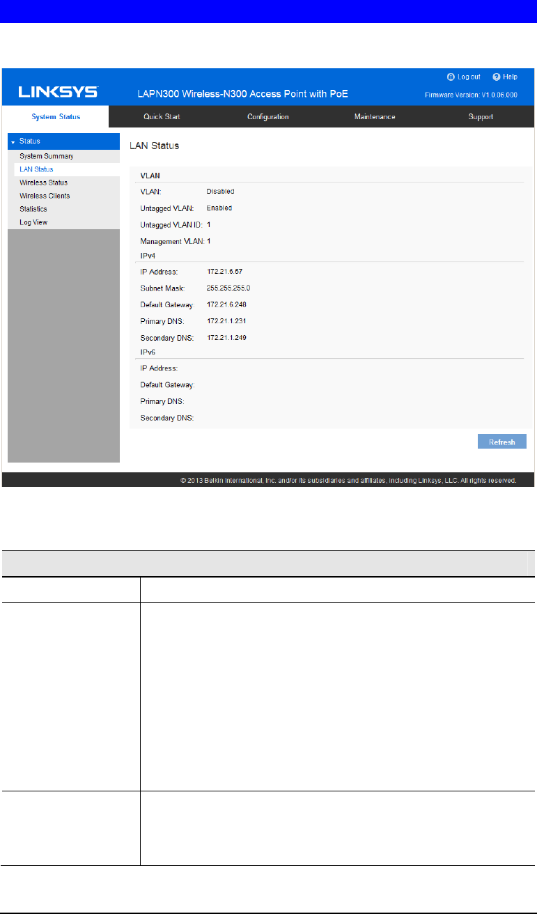
LAN Status
LAN Status displays settings, and status of LAN interface.
Figure 33: LAN Status Screen
Data - LAN Status
VLAN
VLAN Enabled or disabled (default).
Untagged VLAN Enabled (default) or disabled.
When enabled, and if its VLAN ID is equal to Untagged VLAN
ID, all traffic is untagged when sent from LAN ports. Untagged
traffic can be accepted by LAN ports. If disabled, traffic is always
tagged when sent from LAN port and only tagged traffic can be
accept from LAN port.
By default all traffic on the access point uses VLAN 1, the default
untagged VLAN. This means that all traffic is untagged until you
disable the untagged VLAN, change the untagged traffic VLAN
ID, or change the VLAN ID for a SSID.
Untagged VLAN ID Displays the untagged VLAN ID. Traffic on the VLAN that you
specify in this field is not be tagged with a VLAN ID when for-
warded to the network. VLAN 1 is the default ID for untagged
VLAN and management VLAN.

52
Management VLAN Displays the Management VLAN ID. The VLAN associated with
the IP address you use to connect to the access point. Provide a
number between 1 and 4094 for the Management VLAN ID. The
default is 1.
This VLAN is also the default untagged VLAN. If you already
have a management VLAN configured on your network with a
different VLAN ID, you must change the VLAN ID of the man-
agement VLAN on the access point.
IPv4/v6
IP Address The IP address of the wireless access point.
Subnet Mask The Network Mask (Subnet Mask) for the IP address above.
Default Gateway Enter the gateway for the LAN segment to which the wireless
access point is attached (the same value as the PCs on that LAN
segment).
Primary DNS The primary DNS address provided by the DHCP server or
configured manually.
Secondary DNS The secondary DNS address provided by the DHCP server or
configured manually.
53
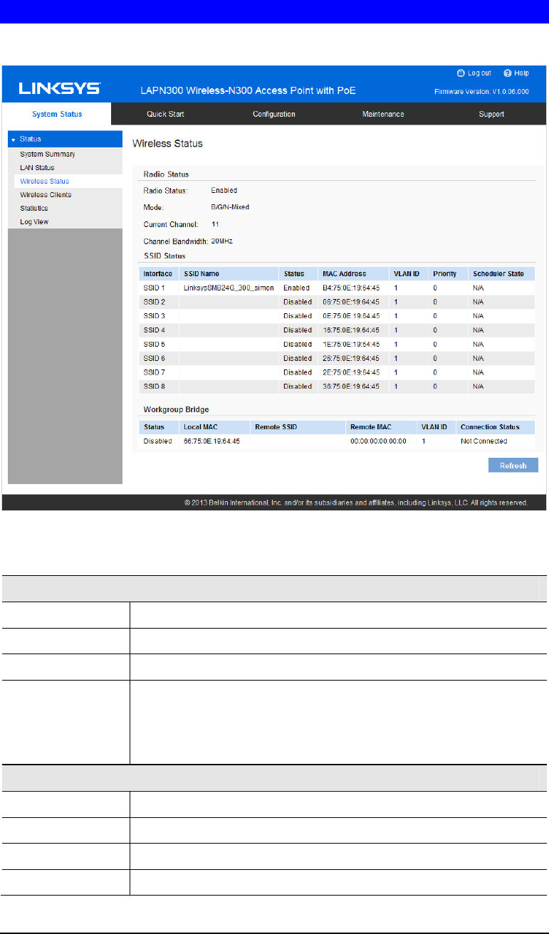
Wireless Status
Wireless Status displays settings and status of wireless radio and SSIDs.
Figure 34: Wireless Status Screen
Data - Wireless Status
Radio Status
Radio Status Indicates whether the radio is enabled.
Mode Current 802.11mode (a/b/g/n) of the radio.
Channel The channel currently in use.
Channel
Bandwidth Current channel bandwidth of the radio.
When set to 20 MHz, only the 20 MHz channel is in use. When set to
40 MHz, Wireless-N connections will use 40 MHz channel, but
Wireless-B and Wireless-G will still use 20 MHz channel.
SSID Status
Interface SSID index.
SSID Name Name of the SSID.
Status Status of the SSID, enabled or disabled.
MAC Address MAC Address of the SSID.

54
VLAN ID VLAN ID of the SSID.
Priority The 802.1p priority of the SSID.
Scheduler State Current scheduler status of the SSID.
• N/A
No scheduler is enabled on the SSID, or the SSID is disabled
by administrator.
• Active
The SSID is enabled.
• Inactive
The SSID is disabled.
Workgroup Bridge Status
Status Status of the Workgroup Bridge: enabled or disabled.
Local MAC MAC address of the Workgroup Bridge.
Remote SSID SSID of the destination access point on the other end of the
Workgroup Bridge link to which data is sent and from which data is
received.
Remote MAC MAC address of the destination access point on the other end of the
Workgroup Bridge link to which data is sent and from which data is
received.
Connection Status Status of the Workgroup Bridge: disabled, connected or not con-
nected.
55
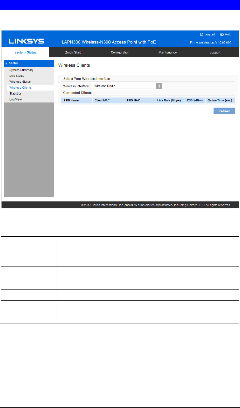
Wireless Clients
Wireless Clients screen displays list of connected clients based on each wireless interface.
Figure 35: Wireless Clients Screen
Data - Wireless Clients
Wireless Interface Select the desired interface from the list. The interfaces include 8
SSIDs per radio.
SSID Name Name of the SSID to which the client connects.
Client MAC The MAC address of the client.
SSID MAC MAC of the SSID to which the client connects.
Link Rate The link rate of the client. Unit is Mbps.
RSSI The signal strength of the client. Unit is dBm.
Online Time How long this client has been online. Unit is seconds.
56
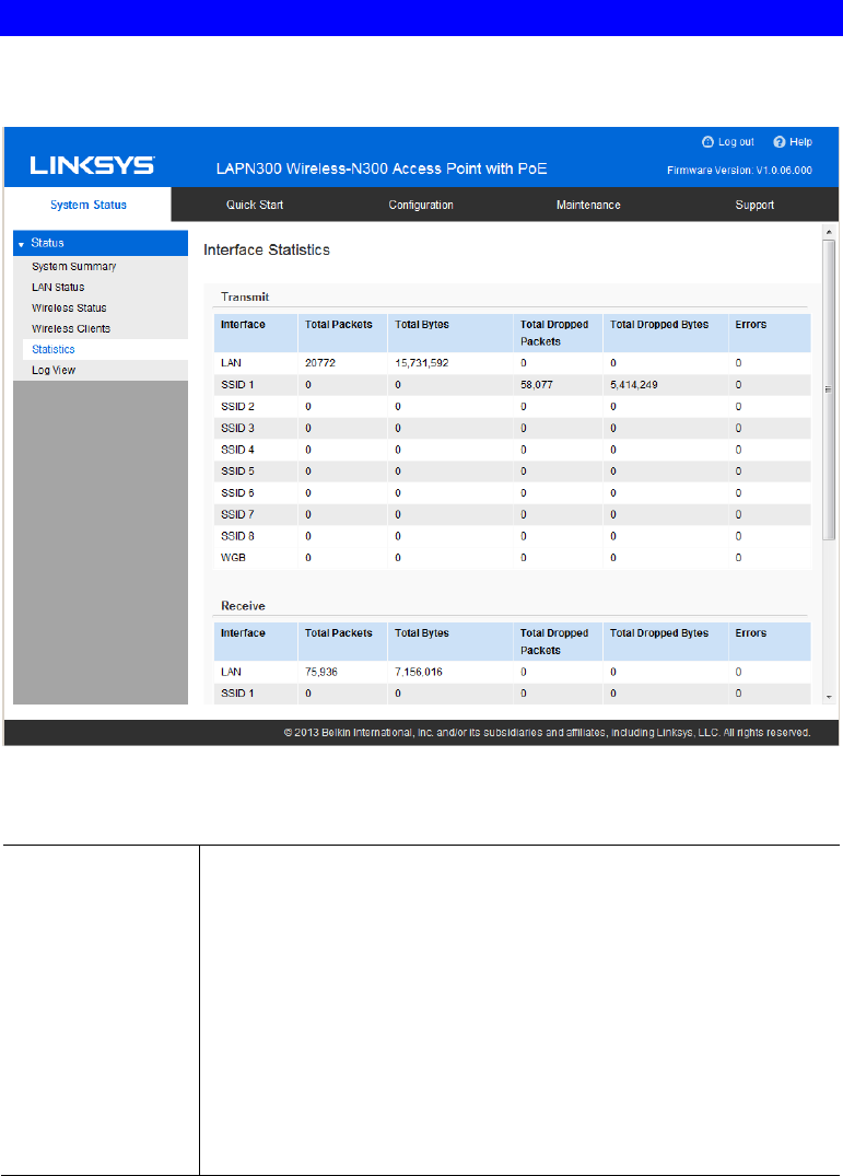
Statistics
Statistics provides real-time transmitted and received statistics data based on each SSID and
LAN interface.
Figure 36: Statistics Screen
Data - Statistics
Transmit/Receive • Total Packets - The total packets sent (in Transmit table) or re-
ceived (in Received table) by the interface.
• Total Bytes - The total bytes sent (in Transmit table) or received
(in Received table) by the interface.
• Total Dropped Packets - The total number of dropped packets sent
(in Transmit table) or received (in Received table) by the interface.
• Total Dropped Bytes - The total number of dropped bytes sent (in
Transmit table) or received (in Received table) by the interface.
• Errors - The total number of errors related to sending and receiving
data on this interface.
57
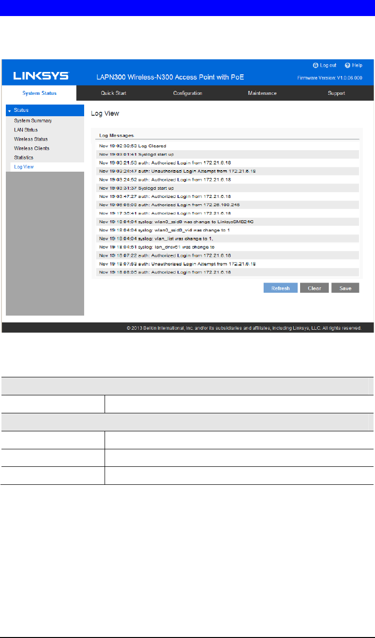
Log View
Log View shows a list of system events that are generated by each single log entry, such as
login attempts and configuration changes.
Figure 37: Log View Screen
Data - Log View
Log Messages
Log Messages Show the log messages.
Buttons
Refresh Update the data on screen.
Save Save the log to a file on your PC.
Clear Delete the existing logs from device.

58
Chapter 4
Access point Management
Overview
This chapter covers features available on the wireless access point’s Maintenance menu.
• Maintenance
• Firmware Upgrade
• Configuration Backup/Restore
• Factory Default
• Reboot
• Diagnostics
• Ping Test
• Packet Capture
• Diagnostic Log
Firmware Upgrade
The firmware (software) in the wireless access point can be upgraded by using HTTP/HTTPS,
or TFTP.
Check Linksys support website (http://www.linksys.com/business/support) and download the
latest firmware release to your storage such as PC. Then, perform firmware upgrade by
following the steps below.
During firmware upgrade, do not power off device or disconnect Ethernet cable. Device will
reboot automatically after firmware upgrade is completed.
4

59
Figure 38: Firmware Upgrade Screen
To perform the firmware upgrade from local PC:
1. Click the Browse button and navigate to the location of the upgrade file.
2. Select the upgrade file. Its name will appear in the Upgrade File field.
3. Click the Upgrade button to commence the firmware upgrade.
To perform the firmware upgrade from TFTP server:
1. Enter the IP address of the TFTP server and the source file. The source file is the firmware
filename you stored in your TFTP server. Only support IPv4 address here.
2. Click the Upgrade button to commence the firmware upgrade.
60
Configuration
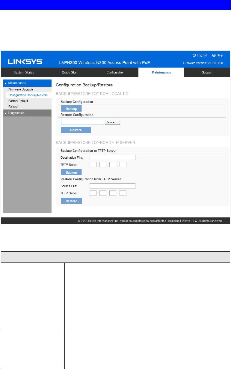
Configuration backup/restore allows you to download the configuration file from device to
external storage, e.g., your PC, or network storage, or to upload a previously saved configura-
tion file from external storage to device. It is highly recommended you save one extra copy of
the configuration file to external storage after you are done with access point setup.
Figure 39: Configuration Backup/Restore Screen
Data - Configuration Backup/Restore Screen
Backup/Restore to/from Local PC
Backup
Configuration Once you have the access point working properly, you should
back up the settings to a file on your computer. You can later
restore the access point's settings from this file, if necessary.
To create a backup file of the current settings:
• Click Backup.
• If you don't have your browser set up to save downloaded
files automatically, locate where you want to save the file,
rename it if you like, and click Save.
Restore
Configuration To restore settings from a backup file:
1. Click Browse.
2. Locate and select the previously saved backup file.
3. Click Restore

61
Backup/Restore to/from TFTP server
Backup
Configuration To create a backup file of the current settings:
1. Enter the destination file name you plan to save in TFTP
server.
2. Enter the IP address for the TFTP server. Only support IPv4
address here.
3. Click Backup
Restore
Configuration To restore settings from a backup file:
1. Enter the source file name stored in TFTP server.
2. Enter the IP address for the TFTP server. Only support IPv4
address here.
3. Click Restore
62
Factory Default
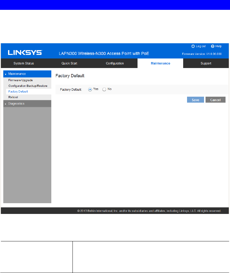
It’s highly recommended you save your current configuration file before you restore to factory
default settings. To save your current configuration file, click Maintenance Æ Configuration
Backup/Restore.
Figure 40: Factory Default Screen
Data - Factory Default Screen
Factory Default If Yes radio button is clicked and Save button is pressed, your
current configuration file will be deleted, and the system will
reboot. The access point will go back to factory default mode
after reboot.
63
Reboot
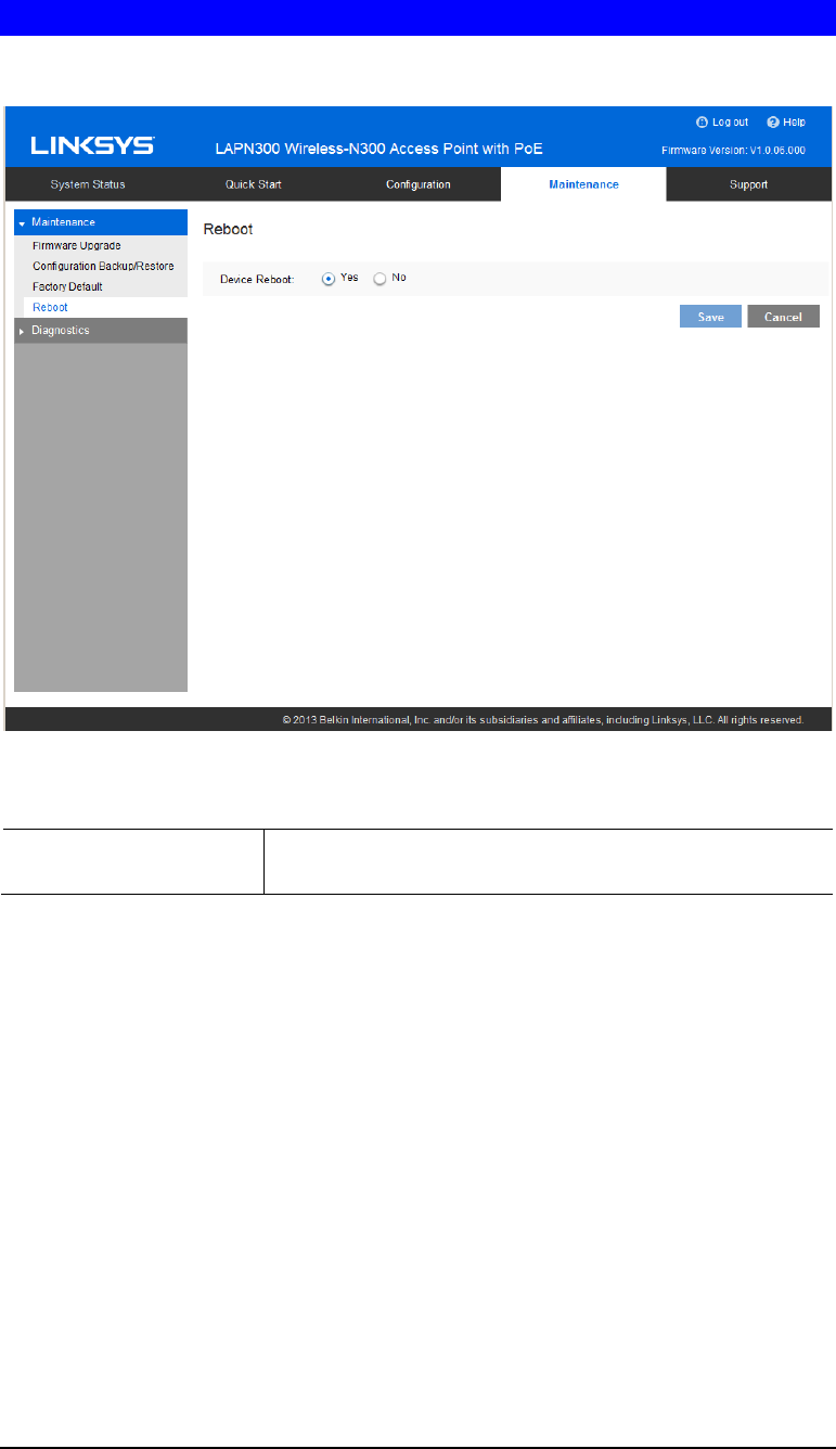
Reboot power cycles the device. The current configuration file will remain after reboot.
Figure 41: Reboot Screen
Data - Reboot Screen
Device Reboot If Yes radio button is checked, device will power cycle after
Save button is pressed.
64
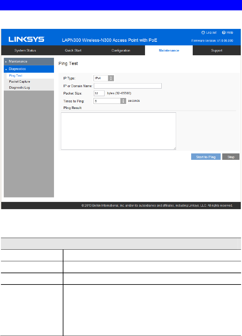
Ping Test
Ping Test is used to determine the accessibility of a host on the network.
Figure 42: Ping Test Screen
Data - Ping Test Screen
General
IP Type Enter the IP type of destination address.
IP or URL Address Enter the IP address or domain name that you want to ping.
Packet Size Enter the size of the packet.
Times to Ping Select the desired number from the drop-list.
• 5
• 10
• 15
• Unlimited
65
Packet Capture
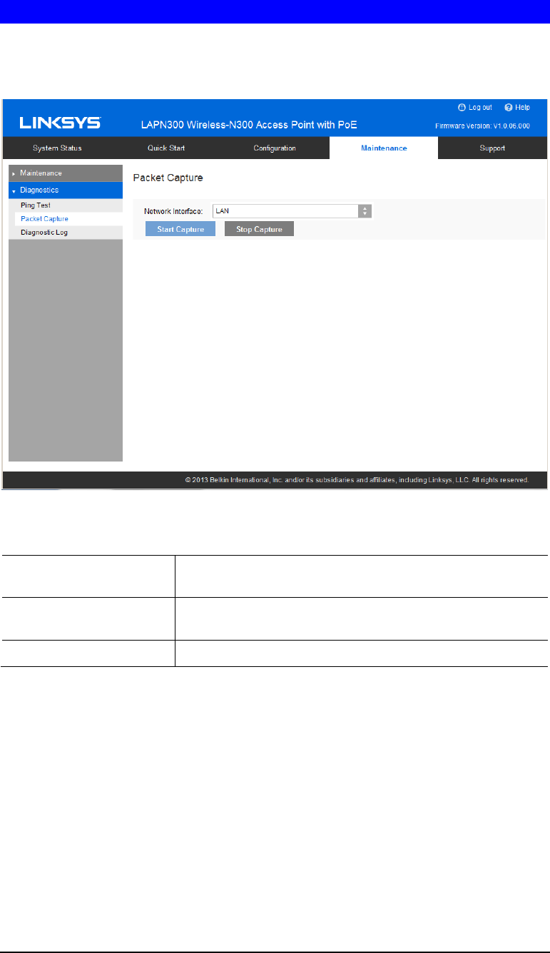
Packet Capture is used to capture and store 802.3 packets received and transmitted by the
access point based on one specified network interface. Network interface can be radio, SSID or
LAN.
Figure 43: Packet Size Screen
Data - Packet Size Screen
Network Interface Select the desired network interface from the drop-down list.
The interface can be Wireless Radio, SSID or Ethernet.
Start Capture Click it to start the capture. You will be asked to specify a
local file to store the packets.
Stop Capture Click it to stop the capture.
66
Diagnostic Log
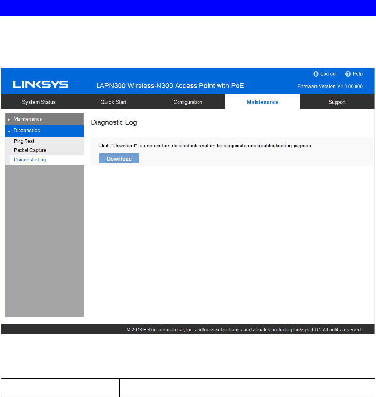
Diagnostic Log provides system detail information, such as configuration file, system status
and statistics data, hardware information, operational status. The information is useful in
troubleshooting and working with technical support.
Figure 44: Diagnostic Screen
Data - Diagnostic Screen
Download Click to download the device diagnostic log into a local file.

67
Appendix A
Troubleshooting
Overview
This chapter covers some common problems encountered while using the wireless access point,
and some possible solutions to them. If you follow the suggested steps and the wireless access
point still does not function properly, contact your dealer for further advice.
General Problems
Problem 1: I can't find new access point on my network.
Solution 1: Check the following.
• The wireless access point is properly installed, LAN connections are
OK, and it is powered ON. Check the LEDs for system and port status.
• Ensure that your PC and the wireless access point are on the same
network segment. (If you don't have a router, this must be the case.)
• You can use the following method to determine the IP address of the
wireless access point, and then try to connect using the IP address, in-
stead of the name.
To Find the access point's IP Address
1. Open a MS-DOS Prompt or Command Prompt Window.
2. Use the Ping command to ping the wireless access point. Enter ping
followed by the default name of the wireless access point. Default name
is a string with “lap” and the last 5 characters of device MAC address.
e.g. ping lap600040
3. Check the output of the ping command to determine the IP address of
the wireless access point, as shown below.
Figure 45: Ping
If your PC uses a Fixed (Static) IP address, ensure that it is using an IP
Address that is in the network segment (subnet) with the wireless access
point. On Windows PCs, you can use Control Panel->Network to check the
Properties for the TCP/IP protocol.
A
68
If there is no DHCP Server found, the wireless access point will roll back to
an IP address and mask of 192.168.1.252 and 255.255.255.0.
Problem 2: My PC can't connect to the LAN via the wireless access point.
Solution 2: Check the following:
• The SSID and security settings on the PC match the settings on the
wireless access point.
• On the PC, the wireless mode is set to "Infrastructure"
• If using the Access Control feature, the PC's name and address is in the
Trusted Stations list.
• If using 802.1x mode, ensure the PC's 802.1x software is configured
correctly. See Chapter 4 for details of setup for the Windows XP
802.1x client. If using a different client, refer to the vendor's docu-
mentation.

69
Appendix B
About Wireless LANs
Overview
Wireless networks have their own terms and jargon. It is necessary to understand many of
these terms in order to configure and operate a wireless LAN.
Wireless LAN Terminology
Modes
Wireless LANs can work in either of two (2) modes:
• Ad-hoc
• Infrastructure
Ad-hoc Mode
Ad-hoc mode does not require an access point or a wired (Ethernet) LAN. Wireless
stations, e.g., notebook PCs with wireless cards communicate directly with each other.
Infrastructure Mode
In Infrastructure Mode, one or more access points are used to connect wireless stations,
e.g., notebook PCs with wireless cards to a wired (Ethernet) LAN. The wireless stations
can then access all LAN resources.
Access points can only function in "Infrastructure" mode,
and can communicate only with wireless stations that are set
to "Infrastructure" mode.
SSID/ESSID
BSS/SSID
A group of wireless stations and a single access point, all using the same ID (SSID), form
a Basic Service Set (BSS).
Using the same SSID is essential. Devices with different SSIDs are unable to communi-
cate with each other.
ESS/ESSID
A group of wireless stations, and multiple access points, all using the same ID (ESSID),
form an Extended Service Set (ESS).
Different access points within an ESS can use different channels. To reduce interference, it
is recommended that adjacent access points SHOULD use different channels.
B

70
As wireless stations are physically moved through the area covered by an ESS, they will
automatically change to the access point that has the least interference or best performance.
This capability is called Roaming. (Access points do not have or require roaming capabili-
ties.)
Channels
The wireless channel sets the radio frequency used for communication.
• Access points use a fixed channel. You can select the channel used. This allows you
to choose a channel that provides the least interference and best performance. For
USA and Canada, the following channels are available.
2.4GHz:
2.412 to 2.462 GHz; 11 channels
5GHz:
• 5.180 to 5.320 GHz; 8 channels
• 5.500 to 5.700 GHz, 8 channels (excludes 5.600 to 5.640 GHz)
• 5.745 to 5.825 GHz; 5 channels
• If using multiple access points it is better if adjacent access points use different
channels to reduce interference. The recommended channel spacing between adjacent
access points is five channels, e.g., use Channels 1 and 6, or 6 and 11.
• In "Infrastructure" mode wireless stations normally scan all channels looking for an
access point. If more than one access point can be used, the one with the strongest
signal is used. (This can only happen within an ESS.)
• If using "Ad-hoc" mode (no access point) all wireless stations should be set to use the
same channel. However, most wireless stations will still scan all channels to see if
there is an existing "Ad-hoc" group they can join.
WEP
WEP (Wired Equivalent Privacy) is a standard for encrypting data before it is transmitted. This
is desirable because it is impossible to prevent snoopers from receiving any data which is
transmitted by your wireless stations. If the data is encrypted, it is meaningless unless the
receiver can decrypt it.
If WEP is used, the wireless stations and the wireless access point must have the same
settings.
WPA-PSK
In WPA-PSK, like WEP, data is encrypted before transmission. WPA is more secure than
WEP. The PSK (Pre-shared Key) must be entered on each wireless station. The 256-bit
encryption key is derived from the PSK, and changes frequently.
WPA2-PSK
This is a further development of WPA-PSK, and offers even greater security, using the AES
(Advanced Encryption Standard) method of encryption. It should be used if possible.

71
WPA-Enterprise
This version of WPA requires a RADIUS server on your LAN to provide the client authentica-
tion according to the 802.1X standard. Data transmissions are encrypted using the WPA
standard.
If this option is used:
• The access point must have a "client login" on the RADIUS server.
• Each user must have a "user login" on the RADIUS server.
• Each user's wireless client must support 802.1X and provide the login data when
required.
All data transmission is encrypted using the WPA standard. Keys are automatically generated,
so no key input is required.
WPA2-Enterprise
This version of WPA2 requires a RADIUS server on your LAN to provide the client
authentication according to the 802.1X standard. Data transmissions are encrypted using the
WPA2 standard.
If this option is used:
• The access point must have a "client login" on the RADIUS server.
• Each user must have a "user login" on the RADIUS server.
• Each user's wireless client must support 802.1X and provide the login data when
required.
All data transmission is encrypted using the WPA2 standard. Keys are automatically generated,
so no key input is required.
802.1x
This uses the 802.1X standard for client authentication, and WEP for data encryption. If
possible, you should use WPA-Enterprise instead, because WPA encryption is much stronger
than WEP encryption.
If this option is used:
• The access point must have a "client login" on the RADIUS server.
• Each user must have a "user login" on the RADIUS server.
• Each user's wireless client must support 802.1X and provide the login data when required.
• All data transmission is encrypted using the WEP standard. You only have to select the
WEP key size; the WEP key is automatically generated.

72
Appendix C
PC and Server
Configuration
Overview
All wireless stations need to have settings that match the wireless access point. These settings
depend on the mode in which the access point is being used.
• If using WEP or WPA2-PSK, it is only necessary to ensure that each wireless station's
settings match those of the wireless access point, as described below.
• For 802.1x modes, configuration is much more complex. The RADIUS server must be
configured correctly, and setup of each wireless station is also more complex.
Using WEP
For each of the following items, each wireless station must have the same settings as the
wireless access point.
Mode On each PC, the mode must be set to Infrastructure.
SSID (ESSID) This must match the value used on the wireless access point.
The default value is LinksysSMB24G for radio 1 and LinksysSMB5G
for radio 2.
Note: The SSID is case sensitive.
Wireless
Security
• Each wireless station must be set to use WEP data encryption.
• The key size (64 bit, 128 bit) must be set to match the access point.
• The key values on the PC must match the key values on the access
point.
Note:
On some systems, the key sizes may be shown as 40-bit and 104-bit
instead of 64-bit, 128-bit. This is because the key input by the user is 24
bits less than the key size used for encryption.
C

73
Using WPA2-PSK
For each of the following items, each wireless station must have the same settings as the
wireless access point.
Mode On each PC, the mode must be set to Infrastructure.
SSID (ESSID) This must match the value used on the wireless access point.
The default value is LinksysSMB24G for radio 1 and
LinksysSMB5G for radio 2.
Note The SSID is case sensitive.
Wireless
Security On each client, wireless security must be set to WPA2-PSK.
• The Pre-shared Key entered on the access point must also be
entered on each wireless client.
• The Encryption method (e.g. TKIP, AES) must be set to match the
access point.

74
Using WPA2-Enterprise
This is the most secure and most complex system.
WPA-Enterprise mode provides greater security and centralized management, but it is more
complex to configure.
Wireless Station Configuration
For each of the following items, each wireless station must have the same settings as the
wireless access point.
Mode On each PC, the mode must be set to Infrastructure.
SSID (ESSID) This must match the value used on the wireless access point.
The default value is LinksysSMB24G for radio 1 and
LinksysSMB5G for radio 2.
Note The SSID is case sensitive.
802.1x
Authentication Each client must obtain a certificate for authentication for the RADIUS
server.
802.1x
Encryption Typically, EAP-TLS is used. This is a dynamic key system, so keys do
NOT have to be entered on each wireless station.
You can also use a static WEP key (EAP-MD5). The wireless access
point supports both methods simultaneously.
RADIUS Server Configuration
If using WPA2-Enterprise mode, the RADIUS server on your network must be configured as
follows.
• It must provide and accept Certificates for user authentication.
• There must be a Client Login for the wireless access point itself.
The wireless access point will use its default name as its client login name. (However, your
RADIUS server may ignore this and use the IP address instead.)
The Shared Key, set on the Security Screen of the access point, must match the Shared Secret
value on the RADIUS server.
• Encryption settings must be correct.

75
802.1x Server Setup (Windows 2000 Server)
This section describes using Microsoft Internet Authentication Server as the RADIUS server,
since it is the most common RADIUS server available that supports the EAP-TLS authentica-
tion method.
The following services on the Windows 2000 Domain Controller (PDC) are also required.
• dhcpd
• dns
• rras
• webserver (IIS)
• RADIUS Server (Internet Authentication Service)
• Certificate Authority
Windows 2000 Domain Controller Setup
1. Run dcpromo.exe from the command prompt.
2. Follow all of the default prompts, ensure that DNS is installed and enabled during installa-
tion.
Services Installation
1. Select the Control Panel -> Add/Remove Programs.
2. Click Add/Remove Windows Components from the left side.
3. Ensure that the following components are selected.
Certificate Services. After enabling this, you will see a warning that the computer cannot be
renamed and joined after installing certificate services. Select Yes to select certificate services
and continue
World Wide Web Server. Select World Wide Web Server on the Internet Information Services
(IIS) component.
From the Networking Services category, select Dynamic Host Configuration Protocol (DHCP),
and Internet Authentication Service (DNS should already be selected and installed).
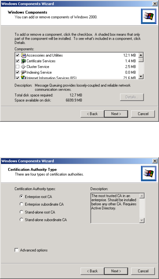
76
Figure 46: Components Screen
4. Click Next.
5. Select the Enterprise root CA, and click Next.
Figure 47: Certification Screen
6. Enter the information for the Certificate Authority, and click Next.
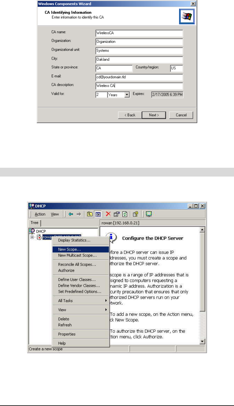
77
Figure 48: CA Screen
7. Click Next if you don't want to change the CA's configuration data.
8. Installation will warn you that Internet Information Services are running, and must be
stopped before continuing. Click OK, then Finish.
DHCP server configuration
1. Click on Start -> Programs -> Administrative Tools -> DHCP
2. Right-click on the server entry, and select New Scope.
Figure 49: DHCP Screen
3. Click Next when the New Scope Wizard Begins.
4. Enter the name and description for the scope, click Next.
5. Define the IP address range. Change the subnet mask if necessary. Click Next.
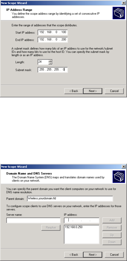
78
Figure 50: IP Address Screen
6. Add exclusions in the address fields if required. If no exclusions are required, leave it
blank. Click Next.
7. Change the Lease Duration time if preferred. Click Next.
8. Select Yes, I want to configure these options now, and click Next.
9. Enter the router address for the current subnet. The router address may be left blank if
there is no router. Click Next.
10. For the parent domain, enter the domain you specified for the domain controller setup, and
enter the server's address for the IP address. Click Next.
Figure 51: DNS Screen
11. If you don't want a WINS server, just click Next.
12. Select Yes, I want to activate this scope now. Click Next, then Finish.
13. Right-click on the server, and select Authorize. It may take a few minutes to complete.
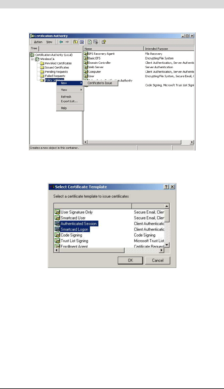
79
Certificate Authority Setup
1. Select Start -> Programs -> Administrative Tools -> Certification Authority.
2. Right-click Policy Settings, and select New -> Certificate to Issue.
Figure 52: Certificate Authority Screen
3. Select Authenticated Session and Smartcard Logon (select more than one by holding down
the Ctrl key). Click OK.
Figure 53: Template Screen
4. Select Start -> Programs -> Administrative Tools -> Active Directory Users and Comput-
ers.
5. Right-click on your active directory domain, and select Properties.
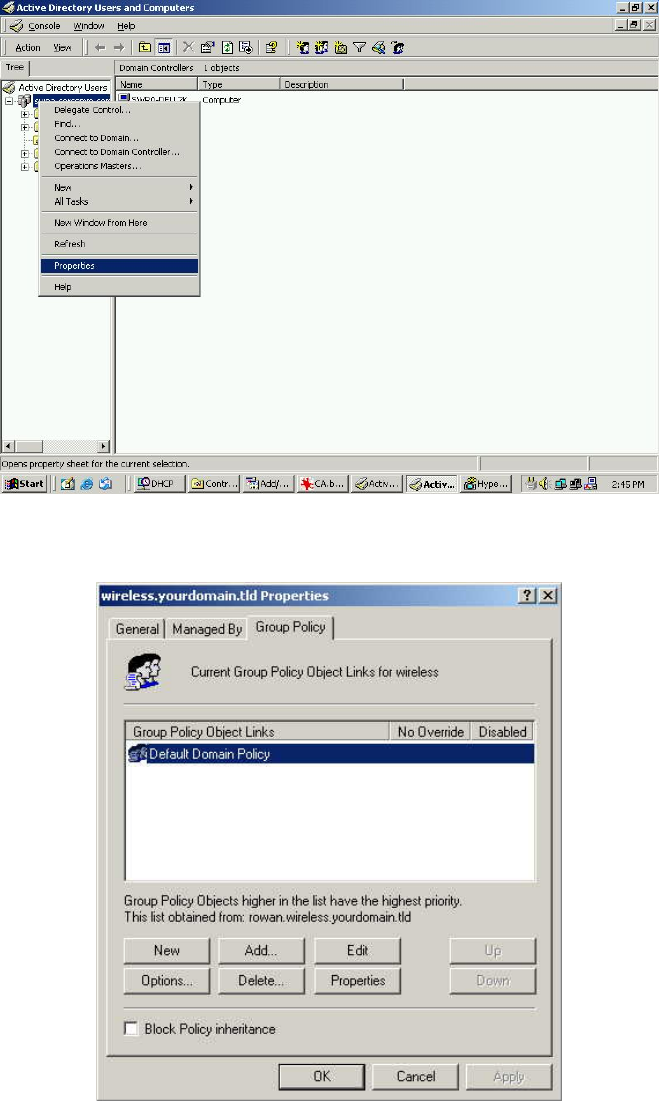
80
Figure 54: Active Directory Screen
6. Select the Group Policy tab, choose Default Domain Policy then click Edit.
Figure 55: Group Policy Tab
7. Select Computer Configuration -> Windows Settings -> Security Settings -> Public Key
Policies, right-click Automatic Certificate Request Settings -> New -> Automatic Certifi-
cate Request.
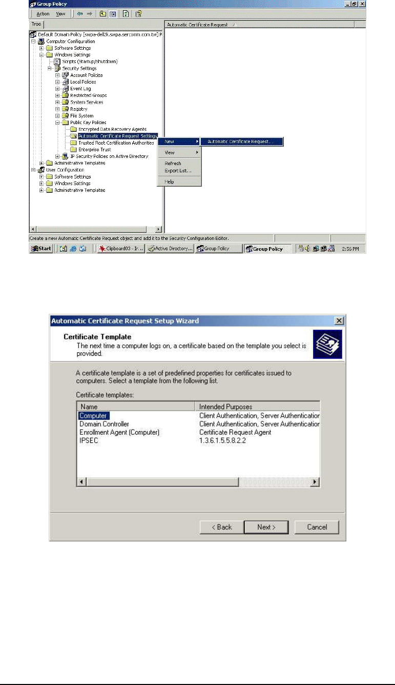
81
Figure 56: Group Policy Screen
8. When the Certificate Request Wizard appears, click Next.
9. Select Computer, click Next.
Figure 57: Certificate Template Screen
10. Ensure that your Certificate Authority is checked, click Next.
11. Review the policy change information and click Finish.
12. Click Start -> Run, type cmd and press enter.
Enter secedit /refreshpolicy machine_policy
This command may take a few minutes to take effect.
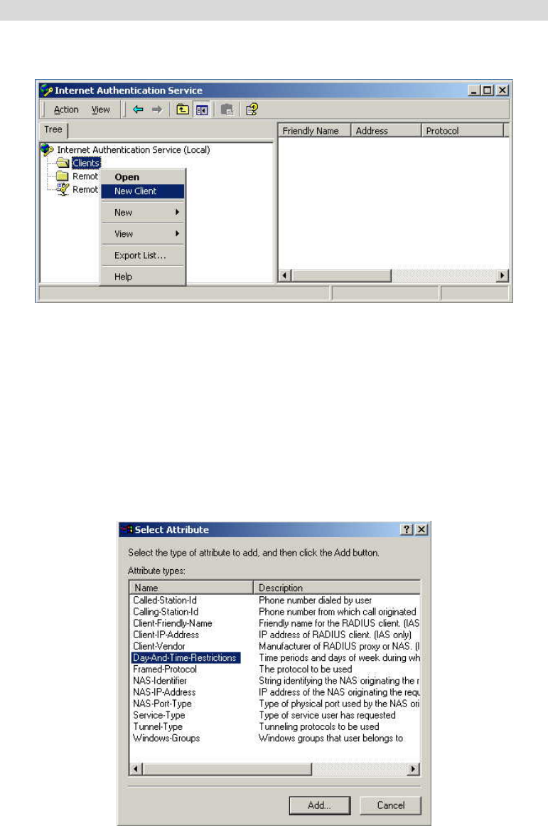
82
Internet Authentication Service (RADIUS) Setup
1. Select Start -> Programs -> Administrative Tools -> Internet Authentication Service
2. Right-click on Clients, and select New Client.
Figure 58: Service Screen
3. Enter a name for the access point, click Next.
4. Enter the address or name of the wireless access point, and set the shared secret, as entered
on the Security Settings of the wireless access point.
5. Click Finish.
6. Right-click on Remote Access Policies, select New Remote Access Policy.
7. Assuming you are using EAP-TLS, name the policy eap-tls, and click Next.
8. Click Add...
If you don't want to set any restrictions and a condition is required, select Day-And-Time-
Restrictions, and click Add...
Figure 59: Attribute Screen
9. Click Permitted, then OK. Select Next.
10. Select Grant remote access permission. Click Next.
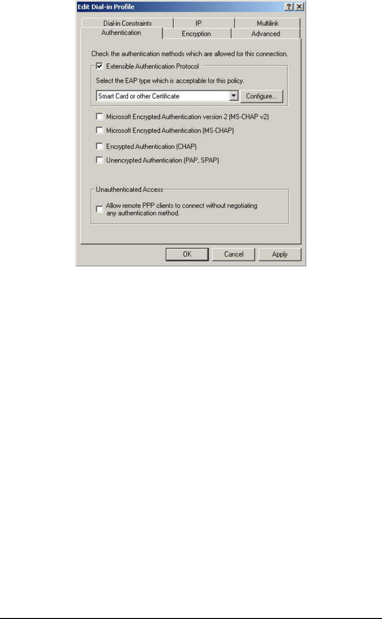
83
11. Click Edit Profile... and select the Authentication tab. Enable Extensible Authentication
Protocol, and select Smart Card or other Certificate. Deselect other authentication me-
thods listed. Click OK.
Figure 60: Authentication Screen
12. Select No if you don't want to view the help for EAP. Click Finish.
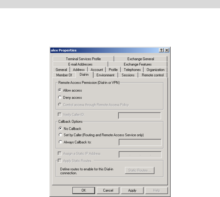
84
Remote Access Login for Users
1. Select Start -> Programs -> Administrative Tools -> Active Directory Users and Comput-
ers.
2. Double click on the user who you want to enable.
3. Select the Dial-in tab, and enable Allow access. Click OK.
Figure 61: Dial-in Screen
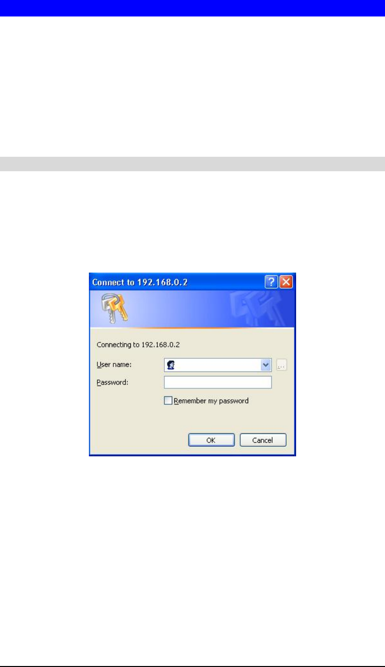
85
802.1x Client Setup on Windows XP
Windows XP ships with a complete 802.1x client implementation. If using Windows 2000,
you can install SP3 (Service Pack 3) to gain the same functionality.
If you don't have either of these systems, you must use the 802.1x client software provided
with your wireless adapter. Refer to your vendor's documentation for setup instructions.
The following instructions assume that:
• You are using Windows XP
• You are connecting to a Windows 2000 server for authentication.
• You already have a login (User-name and password) on the Windows 2000 server.
Client Certificate Setup
1. Connect to a network that doesn't require port authentication.
2. Start your Web browser. In the Address box, enter the IP address of the Windows 2000
Server, followed by /certsrv
e.g
http://192.168.0.2/certsrv
3. You will be prompted for a user name and password. Enter the User name and Password
assigned to you by your network administrator, and click OK.
Figure 62: Connect Screen
4. On the first screen (below), select Request a certificate, click Next.
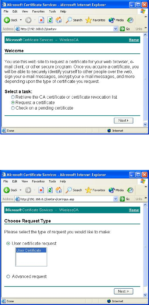
86
Figure 63: Wireless CA Screen
5. Select User certificate request and select User Certificate, click Next.
Figure 64: Request Type Screen
6. Click Submit.
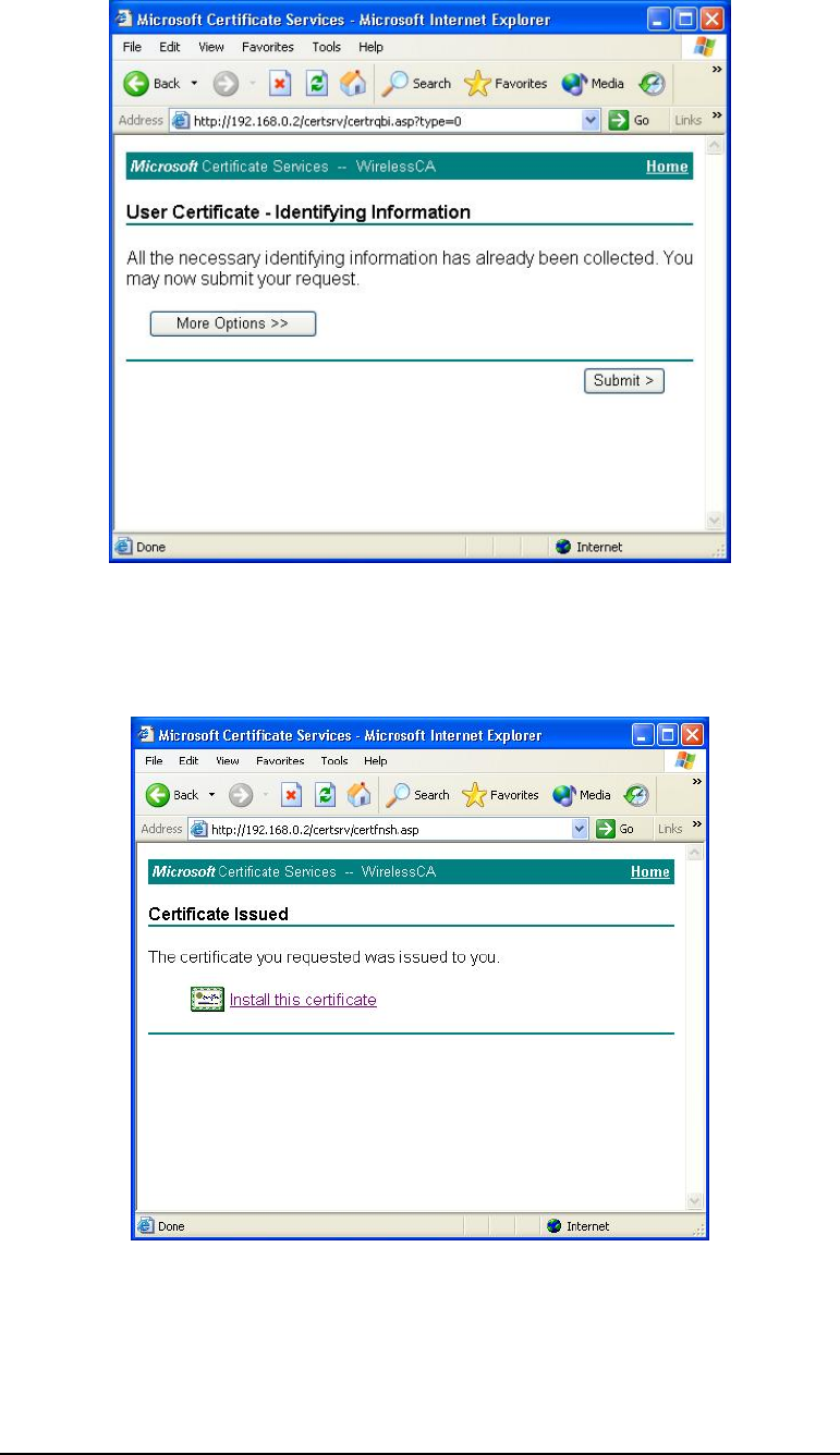
87
Figure 65: Identifying Information Screen
7. A message will be displayed and the certificate will be returned to you.
Click Install this certificate.
Figure 66: Certificate Issued Screen
8. You will receive a confirmation message. Click Yes.
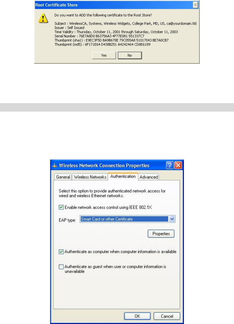
88
Figure 67: Root Certificate Screen
9. Certificate setup is now complete.
802.1x Authentication Setup
1. Open the properties for the wireless connection, by selecting Start - Control Panel -
Network Connections.
2. Right-click on the Wireless Network Connection, and select Properties.
3. Select the Authentication Tab, and ensure that Enable network access control using IEEE
802.1X is selected, and Smart Card or other Certificate is selected from the EAP type.
Figure 68: Authentication Tab
Encryption Settings
The encryption settings must match the access point’s on the wireless network you wish to join.
• Windows XP will detect any available wireless networks, and allow you to configure each
network independently.
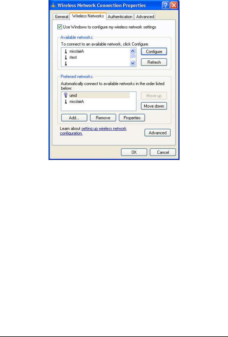
89
• Your network administrator can advise you of the correct settings for each network.
802.1x networks typically use EAP-TLS. This is a dynamic key system, so there is no
need to enter key values.
Enabling Encryption
To enable encryption for a wireless network, follow this procedure.
1. Click on the Wireless Networks tab.
Figure 69: Wireless Networks Screen
2. Select the wireless network from the Available Networks list, and click Configure.
3. Select and enter the correct values, as advised by your Network Administrator.
For example, to use EAP-TLS, you would enable Data encryption, and click the checkbox
for the setting The key is provided for me automatically, as shown below.
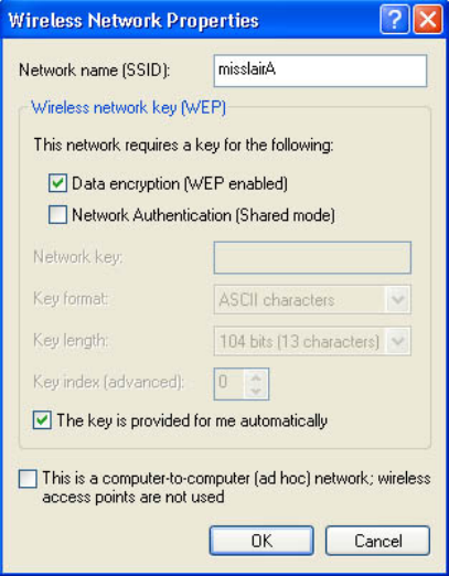
90
Figure 70: Properties Screen
Setup for Windows XP and 802.1x client is now complete.
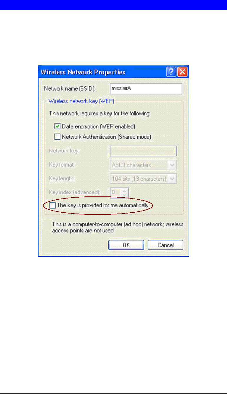
91
Using 802.1x Mode (without WPA)
This is very similar to using WPA-Enterprise.
The only difference is that on your client, you must NOT enable the setting The key is pro-
vided for me automatically.
Instead, you must enter the WEP key manually, ensuring it matches the WEP key used on the
access point.
Figure 71: Properties Screen
Note:
On some systems, the 64-bit WEP key is shown as 40-bit and the 128-bit WEP key is shown
as 104-bit. This difference arises because the key input by the user is 24 bits less than the key
size used for encryption.

92
Regulatory Approvals
Federal Communication Commission Interference Statement
This device complies with Part 15 of the FCC Rules. Operation is subject to the following two
conditions: (1) This device may not cause harmful interference, and (2) this device must accept
any interference received, including interference that may cause undesired operation.
This equipment has been tested and found to comply with the limits for a Class B digital
device, pursuant to Part 15 of the FCC Rules. These limits are designed to provide reasonable
protection against harmful interference in a residential installation. This equipment generates,
uses and can radiate radio frequency energy and, if not installed and used in accordance with
the instructions, may cause harmful interference to radio communications. However, there is
no guarantee that interference will not occur in a particular installation. If this equipment does
cause harmful interference to radio or television reception, which can be determined by turning
the equipment off and on, the user is encouraged to try to correct the interference by one of the
following measures:
• Reorient or relocate the receiving antenna.
• Increase the separation between the equipment and receiver.
• Connect the equipment into an outlet on a circuit different from that
to which the receiver is connected.
• Consult the dealer or an experienced radio/TV technician for help.
FCC Caution: Any changes or modifications not expressly approved by the party responsible
for compliance could void the user's authority to operate this equipment.
This transmitter must not be co-located or operating in conjunction with any other antenna or
transmitter.
Radiation Exposure Statement
This equipment complies with FCC radiation exposure limits set forth for an uncontrolled
environment. This equipment should be installed and operated with minimum distance 20cm
between the radiator & your body.
Note: The country code selection is for non-US model only and is not available to all US
model. Per FCC regulation, all WiFi product marketed in US must fixed to US operation
channels only.
Industry Canada statement
This device complies with RSS-210 of the Industry Canada Rules. Operation is subject to the
following two conditions: (1) This device may not cause harmful interference, and (2) this
device must accept any interference received, including interference that may cause undesired
operation.
Ce dispositif est conforme à la norme CNR-210 d'Industrie Canada applicable aux appareils
radio exempts de licence. Son fonctionnement est sujet aux deux conditions suivantes: (1) le
dispositif ne doit pas produire de brouillage préjudiciable, et (2) ce dispositif doit accepter tout
brouillage reçu, y compris un brouillage susceptible de provoquer un fonctionnement indésira-
ble.
Radiation Exposure Statement
This equipment complies with IC radiation exposure limits set forth for an uncontrolled envi-
ronment. This equipment should be installed and operated with minimum distance 20cm
between the radiator & your body.

93
Déclaration d'exposition aux radiations
Cet équipement est conforme aux limites d'exposition aux rayonnements IC établies pour un
environnement non contrôlé. Cet équipement doit être installé et utilisé avec un minimum de
20 cm de distance entre la source de rayonnement et votre corps.