LINKSYS WAP200E Wireless-G Exterior Access Point with POE User Manual WAP200E User Guide
LINKSYS LLC Wireless-G Exterior Access Point with POE WAP200E User Guide
LINKSYS >
Contents
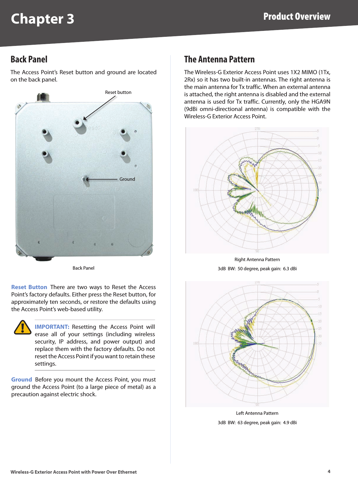
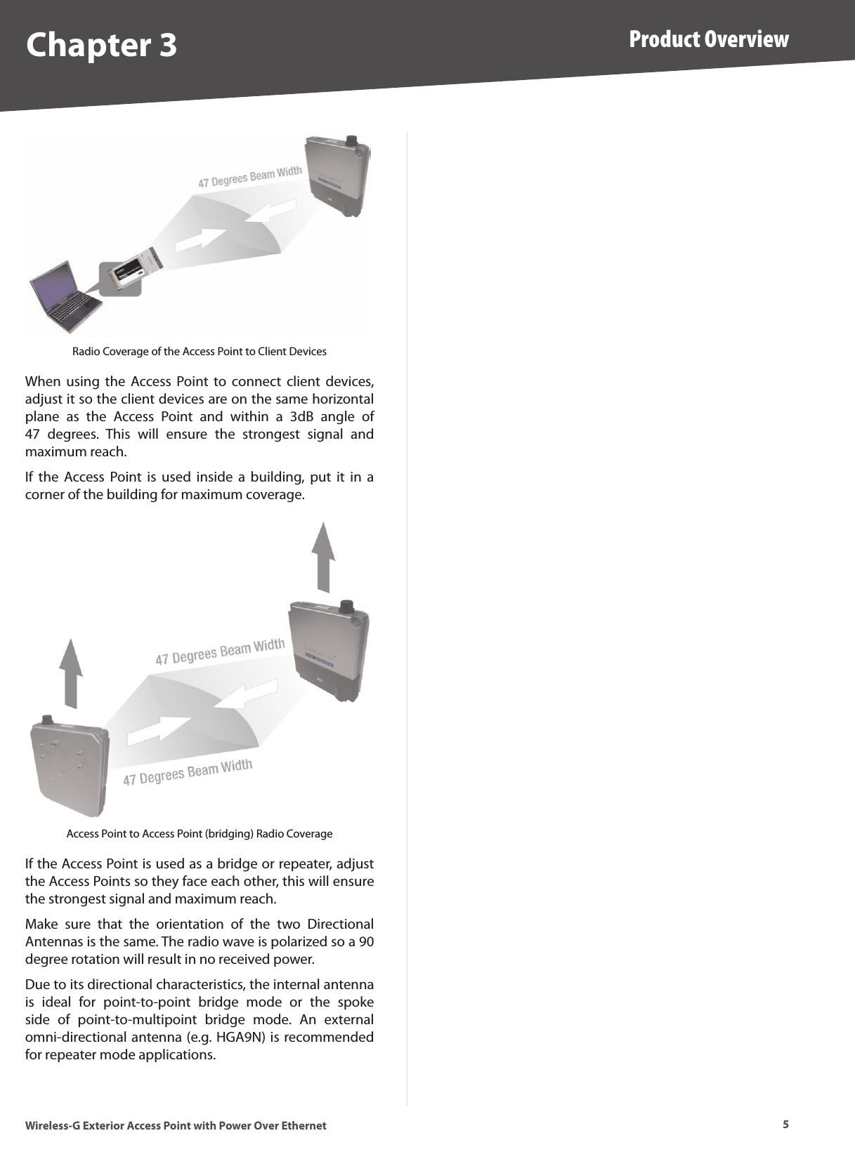
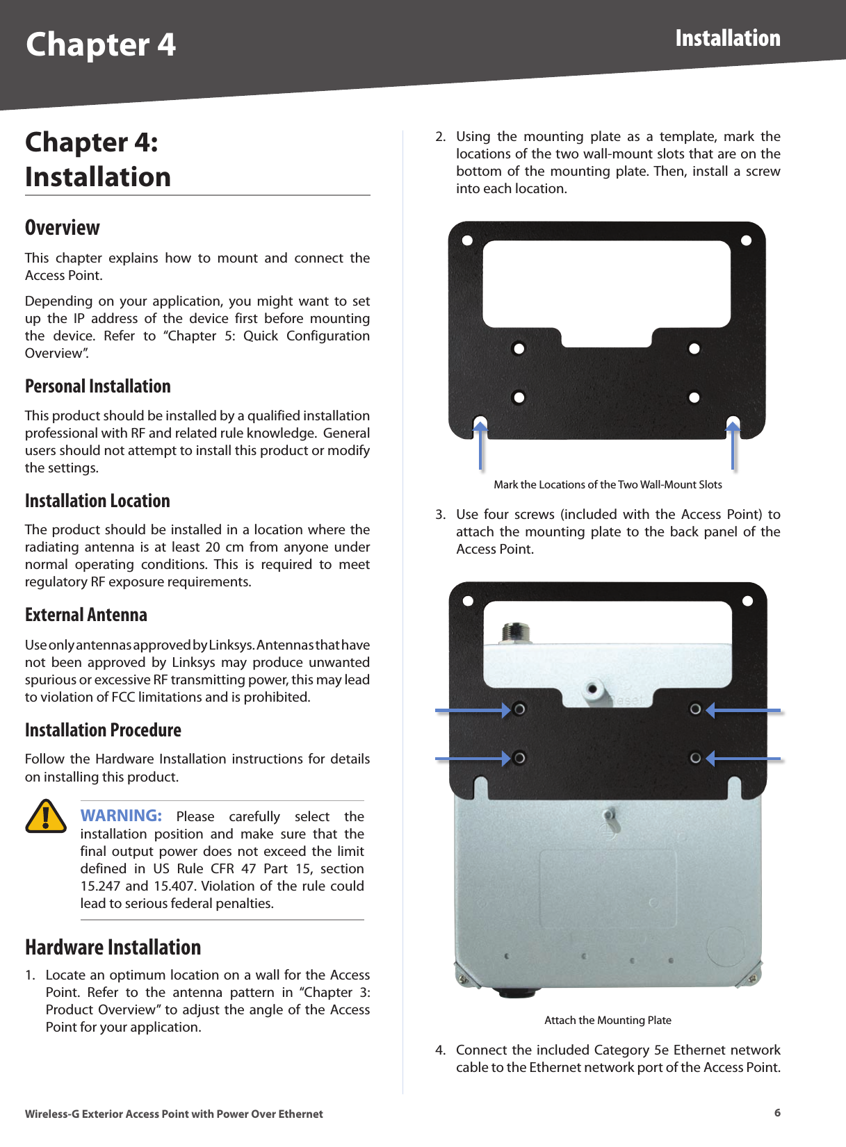
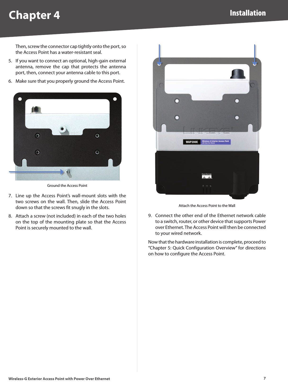
- 1. Manual Part 1
- 2. Manual Part 2
- 3. Manual Part 3
- 4. Manual Part 4
Manual Part 1