LINKSYS WAP4410N Wireless-N Access Point with power over ethernet User Manual Book
LINKSYS LLC Wireless-N Access Point with power over ethernet Book
LINKSYS >
Contents
- 1. User manual 1 of 2
- 2. User manual 2 of 2
User manual 1 of 2
Model No.
Model No.
USER GUIDE
BUSINESS SERIES
Model No.
Model No.
Wireless-N Access Point
with Ports
Model No. WAP4410N
4-portuter
with Power Over Ethernet
Wireless

Wireless-N Access Point with Power Over Ethernet
Copyright and Trademarks
Specifications are subject to change without notice. Linksys is a registered trademark or trademark of Cisco
Systems, Inc. and/or its affiliates in the U.S. and certain other countries. Copyright © 2006 Cisco Systems, Inc. All
rights reserved. Other brands and product names are trademarks or registered trademarks of their respective
holders.
How to Use this User Guide
The user guide to the Wireless-G Exterior Access Point has been designed to make understanding networking
with the Access Point easier than ever. Look for the following items when reading this User Guide:
In addition to these symbols, there are definitions for technical terms that are presented like this:
Also, each figure (diagram, screenshot, or other image) is provided with a figure number and description, like
this:
Figure numbers and descriptions can also be found in the “List of Figures” section.
This exclamation point means there is a caution or
warning and is something that could damage your
property or the Access Point.
word: definition.
This checkmark means there is a note of interest and
is something you should pay special attention to while
using the Access Point.
This question mark provides you with a reminder about
something you might need to do while using the Access Point.
Figure 0-1: Sample Figure Description
WAP4410N-UG-60519NC BW
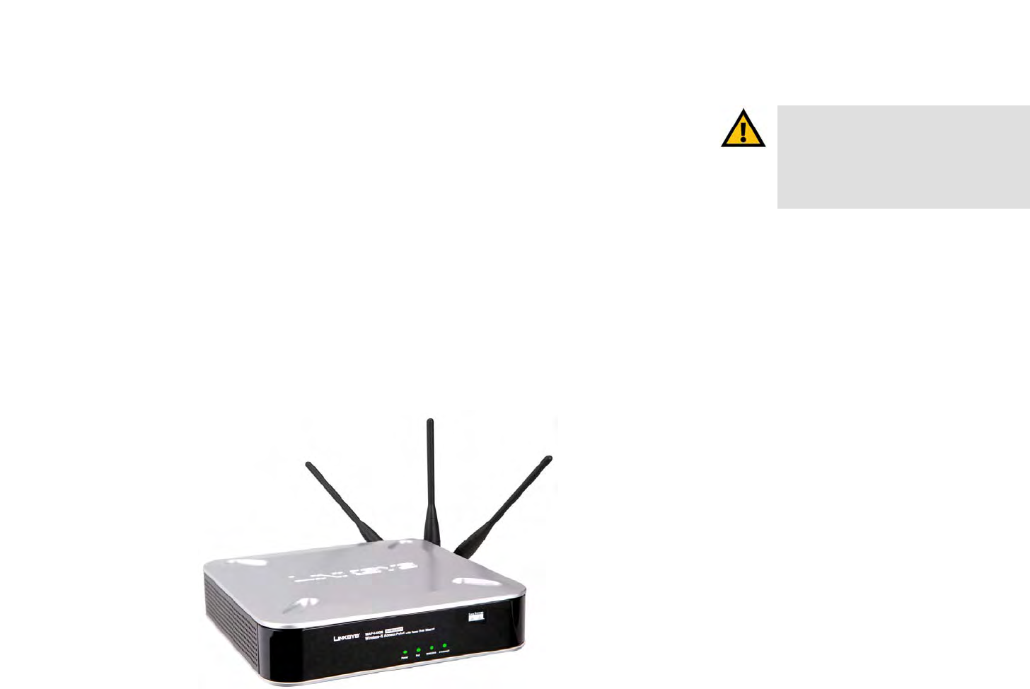
WARNING: This product contains chemicals, including lead, known
to the State of California to cause cancer, and birth defects or other
reproductive harm. Wash hands after handling.

Wireless-N Access Point with Power Over Ethernet
Table of Contents
Chapter 1: Introduction 1
Welcome 1
What’s in this User Guide? 2
Chapter 2: Planning Your Wireless Network 4
Network Topology 4
Roaming 4
Network Layout 4
Example of a simple wireless network 5
Chapter 3: Getting to Know the Wireless-G Exterior Access Point 7
The LEDs 7
The Ports 8
Antennas and Positions 9
Chapter 4: Connecting the Wireless-N Access Point 11
Overview 11
Connection 11
Placement Options 12
Chapter 5: Setting Up the Wireless-N Access Point 13
Overview 13
Accessing the Utility 13
Navigating the Utility 14
Chapter 6: Configuring the Wireless-N Access Point 16
The Setup - Basic Setup Tab 16
The Setup - Time Tab 17
The Wireless - Basic Wireless Settings Tab 18
The Wireless - Wireless Security Tab 20
The Wireless - Wireless Connection Control Tab 24
The Wireless - Advanced Wireless Settings Tab 25
The Security Monitor Tab 27
The Administration - Management Tab 28
The Administration - Log Tab 30
The Administration - Factory Default Tab 32
The Administration - Firmware Upgrade Tab 32

Wireless-N Access Point with Power Over Ethernet
The Administration - Reboot Tab 33
The Administration - Config Management Tab 34
The Status - Local Network Tab 35
The Status - Wireless Tab 36
The Status - System Performance Tab 37
Appendix A: Troubleshooting 39
Frequently Asked Questions 39
Appendix B: Wireless Security 44
Security Precautions 44
Security Threats Facing Wireless Networks 44
Appendix C: Upgrading Firmware 47
Appendix D: Windows Help 48
Appendix E: Glossary 49
Appendix F: Specifications 54
Appendix G: Warranty Information 56
Appendix H: Regulatory Information 57
Appendix I: Contact Information 63

Wireless-N Access Point with Power Over Ethernet
List of Figures
Figure 2-1: Example of a Simple Wireless Network 5
Figure 3-1: Front Panel 7
Figure 3-2: Back View 8
Figure 3-3: Stackable Position and its Antenna Setup 9
Figure 3-4: Standalone Position and its Antenna Setup 10
Figure 4-1: Connect the Ethernet Cable 11
Figure 4-2: Connect the Power 11
Figure 4-3: The Stand Option 12
Figure 4-4: Stand 12
Figure 4-5: Mounting Dimensions 12
Figure 5-1: Login Screen 14
Figure 6-1: Setup - Static IP Address 16
Figure 6-2: Setup - Automatic Configuration - DHCP 17
Figure 6-3: Setup - Time 17
Figure 6-4: Wireless - Basic Wireless Settings 18
Figure 6-5: Pop-up message on Auto Channel Selection 18
Figure 6-6: Wireless - Wireless Security (Disabled) 20
Figure 6-7: Wireless - Wireless Security (WPA-Personal) 20
Figure 6-8: Wireless - Wireless Security (WPA2-Personal) 21
Figure 6-9: Wireless - Wireless Security (WPA2-Personal Mixed) 21
Figure 6-10: Wireless - Wireless Security (WPA-Enterprise) 22
Figure 6-11: Wireless - Wireless Security (WPA2-Enterprise) 22
Figure 6-12: Wireless - Wireless Security (WPA2 - Enterprise Mixed) 23
Figure 6-13: Wireless Settings - WEP 23
Figure 6-14: Wireless - Wireless Connection Control 24
Figure 6-15: Select MAC Address from Wireless Client List 24
Figure 6-16: Wireless - Advanced Wireless 25
Figure 6-17: Security Monitor 27

Wireless-N Access Point with Power Over Ethernet
Figure 6-18: Administration - Management 28
Figure 6-19: The Administration - Log 30
Figure 6-20: Administration - Factory Default 32
Figure 6-21: Administration - Firmware Upgrade 32
Figure 6-22: Administration - Reboot 33
Figure 6-23: Administration - Config
Management 34
Figure 6-24: Status - Local Network 35
Figure 6-25: Status - Wireless 36
Figure 6-26: Status - System Performance 37
Figure C-1: Firmware Upgrade 47

1
Chapter 1: Introduction
Welcome
Wireless-N Access Point with Power Over Ethernet
Chapter 1: Introduction
Welcome
Thank you for choosing the Wireless-N Access Point with Power Over Ethernet. This Access Point will allow you to
network wirelessly better than ever. An access point allows for greater range and mobility within your wireless
network while also allowing you to connect the wireless network to a wired environment. The Wireless-N Access
Point also offers the convenience of Power over Ethernet (PoE) capability (in addition to regular 12VDC power
adaptor), so it can receive data and power over a single Ethernet network cable.
This Access Point supports the latest 802.11n draft Specification by IEEE early 2006. It also support 802.11g and
802.11b clients in a mixed environment. This Access Point currently can support an 11n data rate up to 300
Mbps. Besides the higher data rate, 802.11n technology also promises longer coverage by using multiple
antennas to transmit and receive data streams in different directions. Users are encouraged to update their
firmware through www.linksys.com when 802.11n specification is finalized by IEEE to ensure compatibility with
all the wireless-N devices.
Networks are useful tools for sharing computer resources. You can access one printer from different computers
and access data located on another computer's hard drive. Networks are even used for playing multiplayer video
games. So, networks are not only useful in homes and offices, they can also be fun.
PCs on a wired network create a LAN, or Local Area Network. They are connected with Ethernet cables, which is
why the network is called "wired".
PCs equipped with wireless client cards or adapters can communicate without cumbersome cables. By sharing
the same wireless settings within their transmission radius, they form a wireless network. This is sometimes
called a WLAN, or Wireless Local Area Network. The Access Point bridges wireless networks of 802.11n, 802.11g
and 802.11b standards and wired networks.
Use the instructions in this Guide to help you connect the Access Point, set it up, and configure it to bridge your
different networks. These instructions should be all you need to get the most out of the Access Point.
802.11b: a wireless networking standard that specifies a
maximum data transfer rate of 11Mbps and an operating
frequency of 2.4GHz.
802.11g: a wireless networking standard that specifies a
maximum data transfer rate of 54Mbps, an operating
frequency of 2.4GHz, and backward compatibility with
802.11b devices.
adapter: a device that adds network functionality to your
PC.
ethernet: network protocol defined in IEEE 802.3 standard
that specifies how data is placed on and retrieved from a
common transmission medium.
lan (local area network): the computers and networking
devices that make up your local network.
network: a series of computers or devices connected
together.
poe (power over ethernet): a technology enabling an
Ethernet network cable to deliver both data and power.
access point: a device that allows wireless-equipped
computers and other devices to communicate with each
other and with devices on a wired network. Also used to
expand the range of a wireless network.
802.11n: wireless networking draft standard that specifies
a maximum data rate up to 600Mbps (300Mbps supported
by this device), an operating frequency of 2.4GHz, and
backward compatibility with 802.11b/g devices.

2
Chapter 1: Introduction
What’s in this User Guide?
Wireless-N Access Point with Power Over Ethernet
What’s in this User Guide?
This user guide covers the steps for setting up and using the Wireless-N Access Point.
• Chapter 1: Introduction
This chapter describes the Wireless-N Access Point’s applications and this User Guide.
• Chapter 2: Planning your Wireless Network
This chapter describes the basics of wireless networking.
• Chapter 3: Getting to Know the Wireless-N Access Point
This chapter describes the physical features of the Access Point.
• Chapter 4: Connecting the Wireless-N Access Point
This chapter instructs you on how to connect your Access Point to your network and placement options.
• Chapter 5: Setting up the Wireless-N Access Point
This chapter explains how to perform the most basic setting changes through the Web-based Utility.
• Chapter 6: Configuring the Wireless-G Exterior Access Point
This chapter provides a reference for the available configuration through the Web-based Utility.
• Appendix A: Troubleshooting
This appendix describes some frequently asked questions regarding installation and use of the Wireless-G
Exterior Access Point.
• Appendix B: Wireless Security
This appendix explains the risks of wireless networking and some solutions to reduce the risks.
• Appendix C: Upgrading Firmware
This appendix instructs you on how to upgrade the Access Point’s firmware.
• Appendix D: Windows Help.
This appendix describes some of the ways Windows can help you with wireless networking.
• Appendix E: Glossary
This appendix gives a brief glossary of terms frequently used in networking.
• Appendix F: Specifications
This appendix provides the Access Point’s technical specifications.

3
Chapter 1: Introduction
What’s in this User Guide?
Wireless-N Access Point with Power Over Ethernet
• Appendix G: Warranty Information
This appendix supplies the Access Point’s warranty information.
• Appendix H: Regulatory Information
This appendix supplies the Access Point’s regulatory information.
• Appendix I: Contact Information
This appendix provides contact information for a variety of Linksys resources, including Technical Support.

4
Chapter 2: Planning Your Wireless Network
Network Topology
Wireless-N Access Point with Power Over Ethernet
Chapter 2: Planning Your Wireless Network
Network Topology
A wireless network is a group of computers, each equipped with one or more wireless adapters. Computers in a
wireless network must be configured to share the same radio channel to talk to each other. Several PCs equipped
with wireless cards or adapters can communicate with each other to form an ad-hoc network without the use of
an access point.
Linksys also provides products to allow wireless adaptors to access wired network through a bridge such as the
wireless access point, or wireless router. An integrated wireless and wired network is called an infrastructure
network. Each wireless PC in an infrastructure network can talk to any computer in a wired or wireless network
via the access point or wireless router.
An infrastructure configuration extends the accessibility of a wireless PC to a wired network, and may double the
effective wireless transmission range for two wireless adapter PCs. Since an Access Point is able to forward data
within a network, the effective transmission range in an infrastructure network may be more than doubled since
Access Point can transmit signal at higher power to the wireless space.
Roaming
Infrastructure mode also supports roaming capabilities for mobile users. Roaming means that you can move your
wireless PC within your network and the access points will pick up the wireless PC's signal, providing that they
both share the same wireless network (SSID) and wireless security settings.
This Access Point has 802.11F Inter-Access Point Protocol (IAPP) to complete the roaming process in seconds. If
your wireless networks share the same IP subnet, this will not disrupt your data connection while moving around.
Before you consider roaming, choose a feasible radio channel and optimum access point position. Proper access
point positioning combined with a clear radio signal will greatly enhance performance.
Network Layout
The Wireless-N Access Point has been designed for use with 802.11n, 802.11g and 802.11b products. The
Access Point is compatible with 802.11n, 802.11g and 802.11b adapters, such as the notebook adapters for your
laptop computers, PCI adapters for your desktop PCs, and USB adapters for all PCs when you want to enjoy
infrastructure: a wireless network that is bridged to a wired
network via an access point.
ad-hoc: a group of wireless devices communicating directly
with each other (peer-to-peer) without the use of an access
point.
roaming: the ability to take a wireless device from one
access point's range to another without losing the
connection.
ssid: your wireless network's name
5
Chapter 2: Planning Your Wireless Network
Example of a simple wireless network
Wireless-N Access Point with Power Over Ethernet
wireless connectivity. These wireless products can also communicate with a 802.11n, 802.11g or 802.11b
wireless print server (if available).
To link your wired network with your wireless network, connect the Access Point’s Ethernet network port to any
switch or router with Power over Ethernet (PoE)—or a PoE injector, such as the Linksys WAPPOE or WAPPOE12.
Note that the 12 VDC on the WAPPOE12 is for the splitter output. Both PoE Injectors provide 48 VDC power output.
With these, and many other, Linksys products, your networking options are limitless. Go to the Linksys website at
www.linksys.com for more information about wireless products.
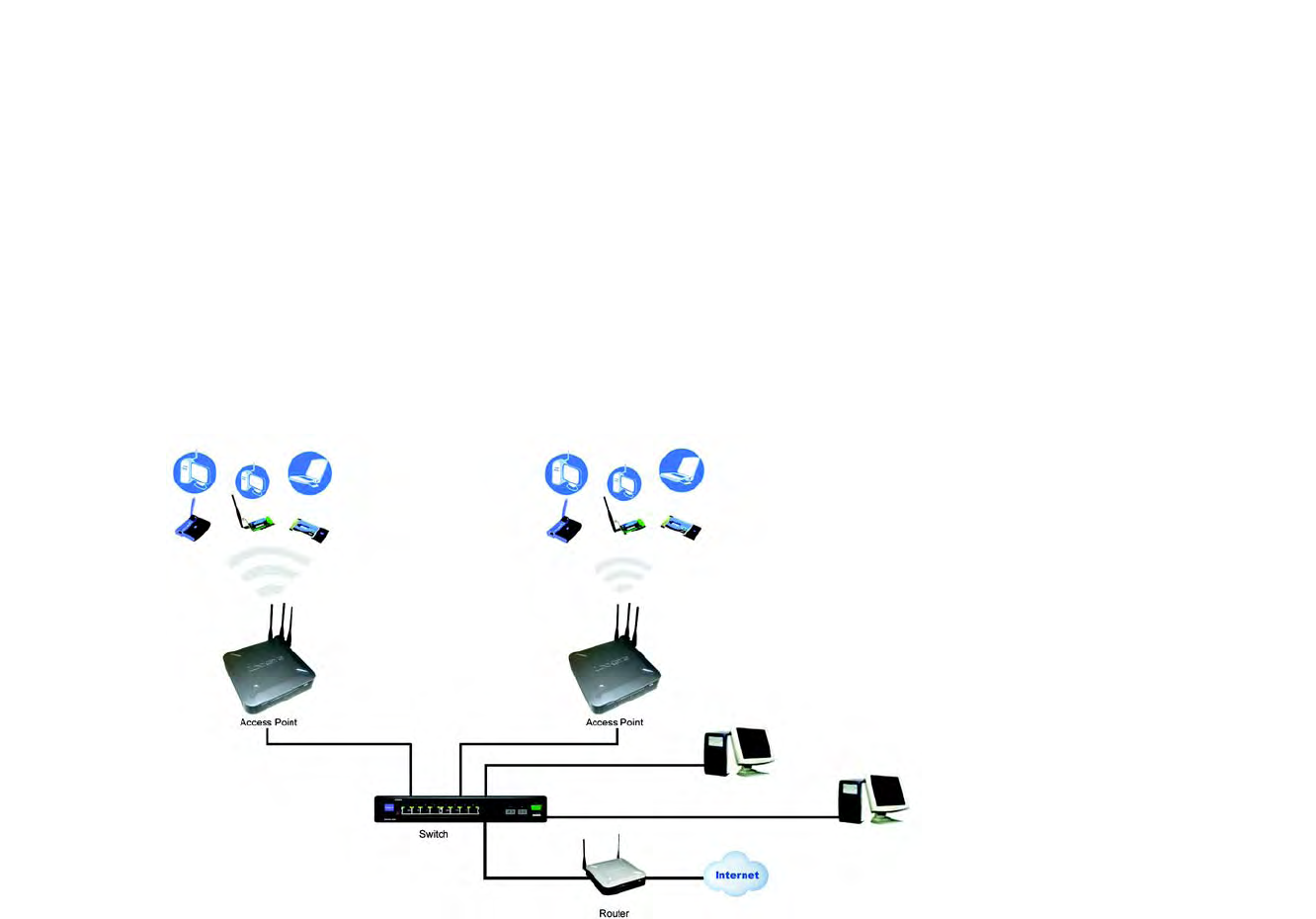
Example of a simple wireless network
Figure 2-1: Example of a Simple Wireless Network

6
Chapter 2: Planning Your Wireless Network
Example of a simple wireless network
Wireless-N Access Point with Power Over Ethernet
The above diagram shows a typical infrastructure wireless network setup. The wireless Access Points are
connecting to a Linksys switch that provides power to the Access Points. Each Access Point can connect multiple
wireless devices to the network. This network will provide connectivity among wireless network devices and PCs
that have a wired connection to the switch.
The switch then can connect to a router that can connect to an ISP to reach global Internet.
7
Chapter 3: Getting to Know the Wireless-G Exterior Access Point
The LEDs
Wireless-N Access Point with Power Over Ethernet
Chapter 3: Getting to Know the Wireless-G Exterior
Access Point
The LEDs
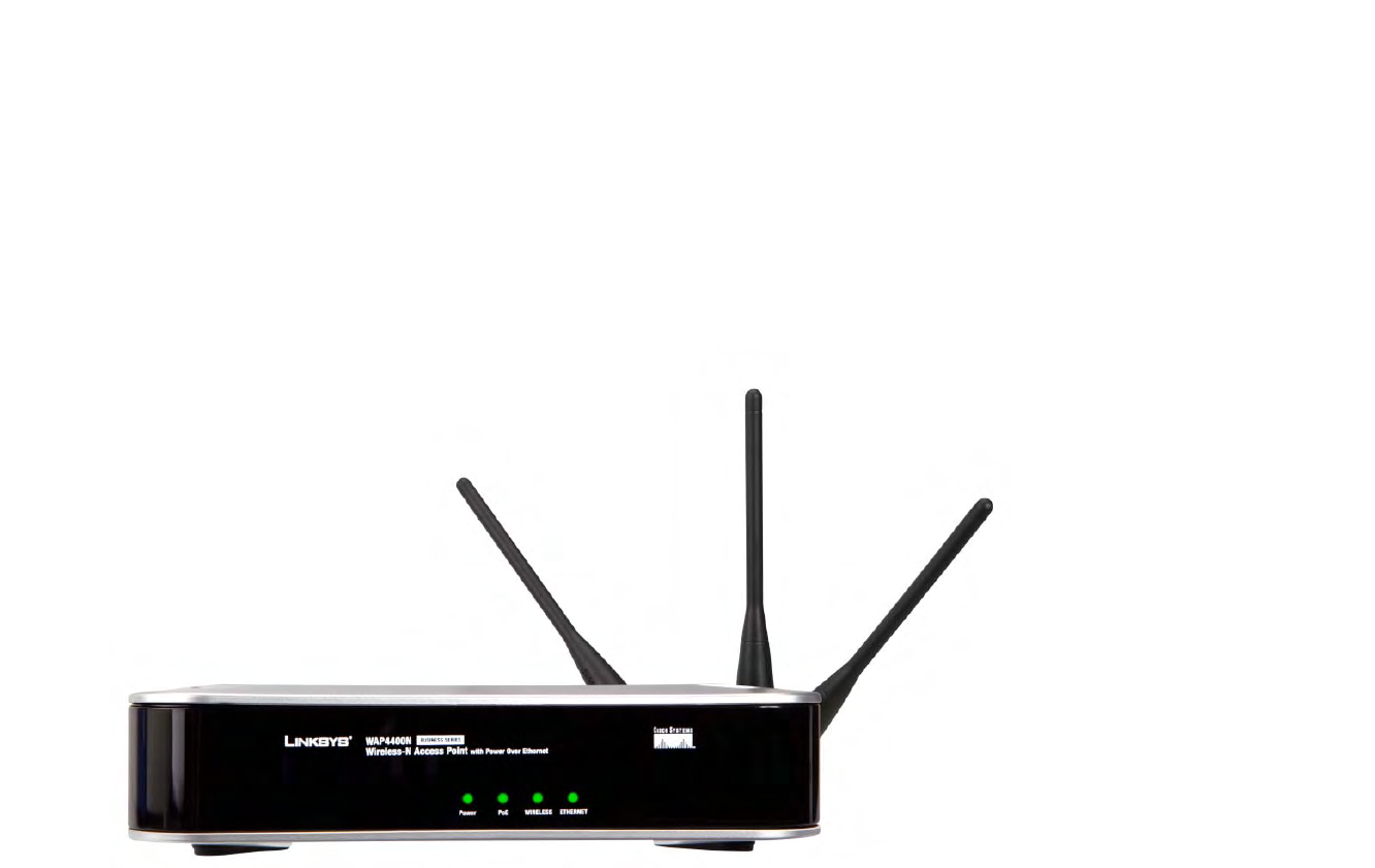
The Access Point's LEDs, where information about network activity is displayed, are located on the front panel.
Power Green. The Power LED lights up when the Access Point is powered on.
PoE Green. The PoE LED lights up when the Access Point is powered through Ethernet cable.
Figure 3-1: Front Panel
8
Chapter 3: Getting to Know the Wireless-G Exterior Access Point
The Ports
Wireless-N Access Point with Power Over Ethernet
WIRELESS Green. The WIRELESS LED lights up when the Access Point is successfully connected to a
wireless device. If the Wireless LED is flashing, the Access Point is actively sending to or
receiving data from a wireless device.
ETHERNET Green. The ETHERNET LED lights up when the Access Point is successfully connected to a
device through the Ethernet network port. If the ETHERNET LED is flashing, the Access Point is
actively sending to or receiving data from one of the devices over the Ethernet network port.
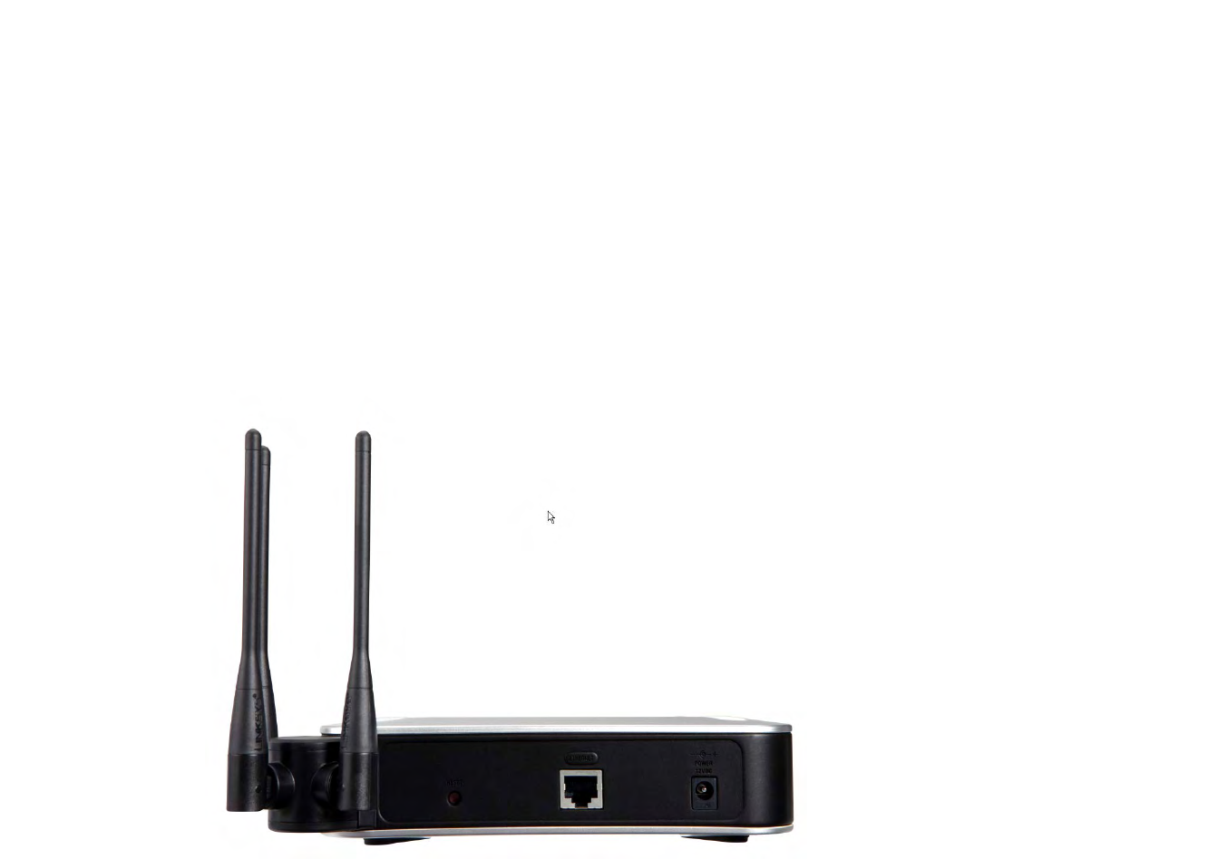
The Ports
The Access Point’s port are located on the back of the device.
port: the connection point on a computer or
networking device used for plugging in
cables or adapters
Figure 3-2: Back View
9
Chapter 3: Getting to Know the Wireless-G Exterior Access Point
Antennas and Positions
Wireless-N Access Point with Power Over Ethernet
Power The Power port connects to the supplied 12VDC power adapter.
Ethernet The Ethernet network port connects to Ethernet network devices, such as a switch or router
that may or may not support Power over Ethernet (PoE).
Reset Button There are two ways to reset the Access Point to the factory default configuration. Either press
the Reset button, for approximately ten seconds, or restore the defaults using the Access
Point's Web-based Utility.
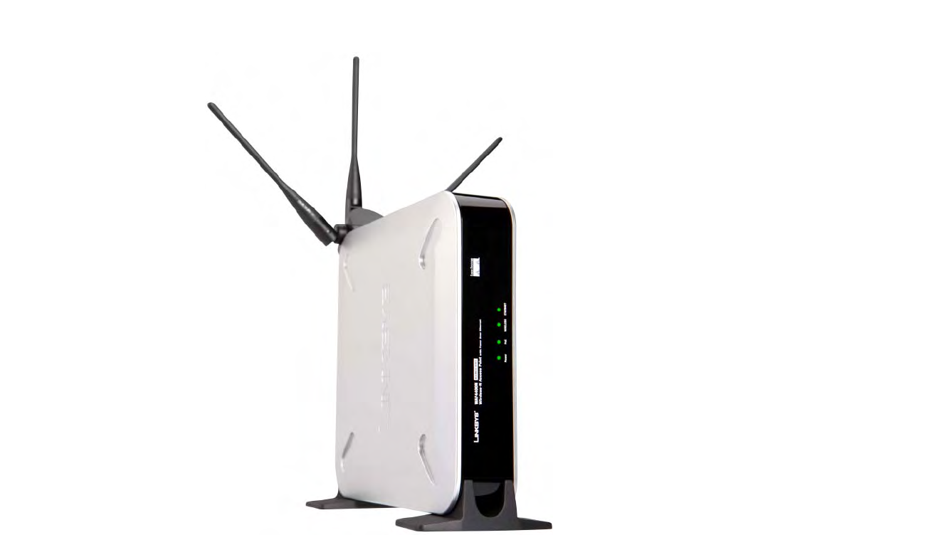
Antennas and Positions
The Access Point’s port are located on the back of the device. The Access Point can be placed in three different
positions. It can be either stackable, standalone, or wall-mount.
Antenna The Access Point has three non-detachable 2dBi omni-directional antennas. The three
antennas have a base that can rotate 90 degrees when in the standing position. The three
antennas will all be used to support 3X3 MIMO diversity in wireless-N mode.
Figure 3-3: Stackable Position and its Antenna Setup
IMPORTANT: Resetting the Access Point will
erase all of your settings (including wireless
security, IP address, and SSID) and replace
them with the factory defaults. Do not reset
the Access Point if you want to retain these
settings.
10
Chapter 3: Getting to Know the Wireless-G Exterior Access Point
Antennas and Positions
Wireless-N Access Point with Power Over Ethernet
Figure 3-4: Standalone Position and its Antenna Setup

11
Chapter 4: Connecting the Wireless-N Access Point
Overview
Wireless-N Access Point with Power Over Ethernet
Chapter 4: Connecting the Wireless-N Access Point
Overview
This chapter explains how to place and connect the Access Point.
Depending on your application, you might want to set up the device first before mounting the device. Refer to
"Chapter 5: Setting Up the Wireless-N Access Point".
Connection
1. Connect your Ethernet network cable to your network router or switch. Then connect the other end of the
network cable to the Access Point’s Ethernet port.
2. If you are using Power Over Ethernet (POE), proceed to the following section, “Placement Options.”
If you are not using POE, then connect the included power adapter to the Access Point’s Power port. Then plug
the power adapter into an electrical outlet. The LEDs on the front panel will light up as soon as the Access
Point powers on.
Proceed to the following section, “Placement Options.”
hardware: the physical aspect of
computers, telecommunications, and
other information technology devices.
Figure 4-1: Connect the Ethernet Cable
Figure 4-2: Connect the Power

12
Chapter 4: Connecting the Wireless-N Access Point
Placement Options
Wireless-N Access Point with Power Over Ethernet
Placement Options
There are three ways to place the Wireless-N Access Point. The first way is to place it horizontally on a surface,
so it sits on its four rubber feet. The second way is to stand the Access Point vertically on a surface. The third way
is to mount it on a wall. The stand and wall-mount options are explained in further detail below.
Stand Option
1. Locate the Access Point’s left side panel.
2. The Access Point includes two stands. With the two large prongs facing outward, insert the short prongs into
the little slots in the Access Point, and push the stand upward until it snaps into place.
Repeat this step with the other stand.
Now that the hardware installation is complete, proceed to “Chapter 5: Setting up the Wireless-N Access
Point,” for directions on how to set up the Access Point."
Wall-Mount Option
1. On the Access Point’s back panel are two criss-cross wall-mount slots.
2. Determine where you want to mount the Access Point, and install two screws that are 2-15/16" apart.
3. Line up the Access Point so that the wall-mount slots line up with the two screws.
4. Place the wall-mount slots over the screws and slide the Access Point down until the screws fit snugly into
the wall-mount slots.
Now that the hardware installation is complete, proceed to “Chapter 5: Setting up the Wireless-N Access
Point,” for directions on how to set up the Access Point."
Figure 4-3: The Stand Option
Figure 4-4: Stand
Figure 4-5: Mounting Dimensions
2-15/16"
Large
Prongs

13
Chapter 5: Setting Up the Wireless-N Access Point
Overview
Wireless-N Access Point with Power Over Ethernet
Chapter 5: Setting Up the Wireless-N Access Point
Overview
The Access Point has been designed to be functional right out of the box with the default settings. However, if
you'd like to change these settings, the Access Point can be configured through your web browser with the Web-
based Utility. This chapter explains how to use the Utility to perform the most basic settings.
The Utility can be accessed via web browsers, such as Microsoft Internet Explorer or Mozilla Firefox through the
use of a computer that is networked with the Access Point.
For a basic network setup, most users only have to use the following screens of the Utility:
• Setup
On the Setup screen, enter your basic network settings (IP address) here.
• Management
Click the Administration tab and then select the Management screen. The Access Point’s default password
is admin. To secure the Access Point, change the AP Password from its default.
Most users will also customize their wireless settings:
• Wireless
On the Wireless screen, change default SSID under the Basic Wireless Settings Tab. Select the level of
security under the Wireless Security Tab and complete the options for the selected security mode.
Accessing the Utility
There are three ways to connect to your Access Point for the first time.
1. If you have a 48VDC Power Injector (e.g. Linksys WAPPOE), power up your Access Point first, then connect the
Injector’s cable to your PC. Configure your PC to have the static IP address on the same subnet as the Access
Point’s default IP address (192.168.1.245).
2. If you have a PoE switch (e.g. Linksys SRW224P), connect your Access Point and your PC to the same
network. Configure your PC to have the static IP address on the same subnet as the Access Point’s default IP
address (192.168.1.245). Or if there is a DHCP server connected to the switch, configure it to assign the IP
address in 192.168.1.0/24 subnet. Your PC will get an IP address in the subnet through the DHCP.
HAVE YOU: Enabled TCP/IP on your PCs? PCs
communicate over the network with this
protocol. Refer to “Appendix D: Windows Help”
for more information on TCP/IP.
browser: an application that provides a way to
look at and interact with all the information on the
World Wide Web.
tcp/ip: a set of protocols PCs use to
communicate over a network.

14
Chapter 5: Setting Up the Wireless-N Access Point
Navigating the Utility
Wireless-N Access Point with Power Over Ethernet
3. Although it is not recommended, you can connect your PC wirelessly to the Access Point when the DHCP
server is connected on the LAN side. It is not recommended, because you can easily lose your connection
through configuration changes.
Launch your web browser, such as Internet Explorer or Mozilla Firefox and enter the Access Point’s default IP
address, 192.168.1.245, in the Address field. Press the Enter key.
Enter admin in the User Name field. The first time you open the Web-based Utility, use the default password,
admin. (You can set a new password from the Administration - Management tab.) Then click the OK button.
After setting up the Access Point to use DHCP or manually configure a new IP address, move your Access Point to
the desired network. You will have to use the new IP address the next time you access the Web-based Utility.
Navigating the Utility
The Web-based Utility consists of the following five main tabs: Setup, Wireless, Security Monitor, Administration,
and Status. Additional screens (sub tabs) will be available from most of the main tabs.
The following briefly describes the main & sub tabs of the Utility.
Setup
Enter the Host Name, IP Address settings, and set the time on this screen.
•Basic Setup. Configure the host name and IP address settings for this Access Point.
• Time. Set the time on this Access Point.
Wireless
You will use the Wireless tabs to enter a variety of wireless settings for the Access Point.
•Basic Wireless Settings. Choose the wireless network mode (e.g. B/G/N-Mixed), SSID, and radio channel on
this screen.
•Wireless Security. Use this screen to configure the Access Point’s security settings.
•Wireless Connection Control. Use this screen to control the wireless connections from client devices to this
Access Point.
Figure 5-1: Login Screen

15
Chapter 5: Setting Up the Wireless-N Access Point
Navigating the Utility
Wireless-N Access Point with Power Over Ethernet
•Advanced Wireless Settings. Use this screen to configure the Access Point’s more advanced wireless settings
(e.g. Tx Rate Limiting, Channel Bandwidth, etc.).
Security Monitor
Use this screen to configure the Access Point’s security monitor capabilities. You will be able to monitor your
wireless network through a client utility on administrator’s PC. This feature works with WPC4400N and future
Linksys client devices.
Administration
You will use the Administration tabs to manage the Access Point.
•Management. This screen allows you to customize the password and Simple Network Management Protocol
(SNMP) settings.
•Log. Configure the Log settings for the Access Point on this screen.
•Factory Default. Use this screen to reset the Access Point to its factory default settings.
•Firmware Upgrade. Upgrade the Access Point’s firmware on this screen.
•Reboot. Use this screen to reboot the Access Point.
•Config Management. You can save the configuration file for the Access Point to your PC, as well as restore the
backup configuration file to the Access Point.
Status
You will be able to view status information for your local network, wireless networks, and network performance.
•Local Network. This screen displays system information, including software & hardware version, MAC
address, and IP address on the LAN side of the Access Point.
•Wireless. This screen displays wireless network settings including SSID, network mode, and wireless
channel.
•System Performance. This screen displays the current traffic statistics of this Access Point for both Wireless
and LAN ports.
firmware: the software image that runs on a
CPU inside a networking device.
snmp: the standard network management protocol
on the Internet.

16
Chapter 6: Configuring the Wireless-N Access Point
The Setup - Basic Setup Tab
Wireless-N Access Point with Power Over Ethernet
Chapter 6: Configuring the Wireless-N Access Point
This chapter is a detailed reference guide for the Web-based Utility. You do not need the Utility to start using your
Access Point. The Access Point has been designed to be functional right out of the box with the default settings.
Besides, you can follow the instructions in “Setting Up the Wireless-N Access Point” on page 13 to perform the
most basic settings without reading through this chapter.
The Setup - Basic Setup Tab
The first screen that appears is the Setup screen. This allows you to change the Access Point's general settings.
Basic Setup
Enter names for the Access Point. The host name can be used to access the Web Utility through the network if
DNS has been set up. The device name is for the benefit of identifying your Access Point after you log in.
Host Name. This is the host name assigned to the Access Point. This host name will be published to your DNS
server if the Access Point is configured to acquire the IP address through DHCP. In that case, Linksys
recommends to follow the company policy on the host name assignment. The default name is Linksys.
Device Name. You may assign any device name to the Access Point. This name is only used by the Access Point
administrator for identification purposes. Unique, memorable names are helpful, especially if you are employing
multiple access points on the same network. The default name is WAP4410N.
Network Setup
The selections under this heading allow you to configure the Access Point’s IP address setting(s).
IP Settings
Select Static IP Address (default) if you want to assign a static or fixed IP address to the Access Point. Then
complete the following:
•IP Address. The IP address must be unique to your network. The default IP address is 192.168.1.245.Figure 6-1: Setup - Static IP Address

17
Chapter 6: Configuring the Wireless-N Access Point
The Setup - Time Tab
Wireless-N Access Point with Power Over Ethernet
•Subnet Mask. The Subnet Mask must be the same as that set on the LAN that your Access Point is connected
to. The default is 255.255.255.0.
Select Automatic Configuration - DHCP if you have a DHCP server enabled on the LAN that can assign an IP
address to the Access Point.
Change these settings as described here and click Save Settings to apply your changes, or click Cancel
Changes to cancel your changes. Help information is displayed on the right-hand side of the screen.
The Setup - Time Tab
This allows you to change the Access Point's time settings. The correct time setting can help the administrator to
search the system log to identify problems.
Time
You can set the time either manually or automatically from a time server if the Access Point can access the public
Internet.
Manually. Select this radio button to set the date and time manually. The default is to set the time manually.
Automatically. Select this option and time zone. The Access Point will contact the public time server to get the
current time.
User Defined NTP Server. Enable this option if you have set up local NTP server. Default is Disabled.
NTP Server IP. Enter the IP address of user defined NTP Server.
Change these settings as described here and click Save Settings to apply your changes, or click Cancel
Changes to cancel your changes. Help information is displayed on the right-hand side of the screen.
Figure 6-2: Setup - Automatic Configuration - DHCP
Figure 6-3: Setup - Time

18
Chapter 6: Configuring the Wireless-N Access Point
The Wireless - Basic Wireless Settings Tab
Wireless-N Access Point with Power Over Ethernet
The Wireless - Basic Wireless Settings Tab
Change the basic wireless network settings on this screen.
Basic Settings
Configure the Wireless Network basic attributes for this Access Point.
SSID Name. The SSID is the unique name shared among all devices in a wireless network. It is case-sensitive,
must not exceed 32 alphanumeric characters, and may be any keyboard character. Make sure this setting is the
same for all devices in your wireless network. The default SSID name is linksys-n.
Wireless Network Mode. Select one of the following modes. The default is B/G/N-Mixed.
B-Only: All the wireless client devices can be connected to the Access Point at Wireless-B data rates with
maximum speed at 11Mbps.
G-Only: Both Wireless-N and Wireless-G client devices can be connected at Wireless-G data rates with
maximum speed at 54Mbps. Wireless-B clients cannot be connected in this mode.
N-Only: Only Wireless-N client devices can be connected at Wireless-N data rates with maximum speed at
300Mbps.
B/G-Mixed: Both Wireless-B and Wireless-G client devices can be connected at their respective data rates.
Wireless-N devices can be connected at Wireless-G data rates.
G/N-Mixed: Both Wireless-G and Wireless-N client devices can be connected at their respective data rates.
Wireless-B clients cannot be connected in this mode.
B/G/N-Mixed: All the wireless client devices can be connected at their respective data rates in this mixed
mode.
Disabled: To disable wireless connectivity completely. This might be useful during system maintenance.
Wireless Channel. Select the appropriate channel to be used among your Access Point and your client devices.
The default is channel 6. You can also select Auto so that your Access Point will select the channel with the
lowest amount of wireless interference while the system is powering up. Auto channel selection will start when
you click Save Settings button, it will take several seconds to scan through all the channels to find the best
Figure 6-4: Wireless - Basic Wireless Settings
Figure 6-5: Pop-up message on Auto Channel Selection

19
Chapter 6: Configuring the Wireless-N Access Point
The Wireless - Basic Wireless Settings Tab
Wireless-N Access Point with Power Over Ethernet
channel. For the Wireless-N 40MHz channel option (see Wireless - Advanced Wireless Settings Tab), the Access
Point will automatically select the adjacent 20MHz channel to combine them into a wider channel.
SSID Broadcast. This option allows the SSID to be broadcast on your network. You may want to enable this
function while configuring your network, but make sure that you disable it when you are finished. With this
enabled, someone could easily obtain the SSID information with site survey software or Windows XP and gain
unauthorized access to your network. Click Enabled to broadcast the SSID to all wireless devices in range. Click
Disabled to increase network security and prevent the SSID from being seen on networked PCs. The default is
Enabled in order to help users configure their network before use.
Change these settings as described here and click Save Settings to apply your changes, or click Cancel
Changes to cancel your changes. Help information is displayed on the right-hand side of the screen, and click
More for additional details.

20
Chapter 6: Configuring the Wireless-N Access Point
The Wireless - Wireless Security Tab
Wireless-N Access Point with Power Over Ethernet
The Wireless - Wireless Security Tab
Change the Access Point’s wireless security settings on this screen.
Wireless Security
Security Mode. Select the wireless security mode you want to use, WPA-Personal, WPA2-Personal, WPA2-
Personal Mixed, WPA-Enterprise, WPA2-Enterprise, WPA2-Enterprise Mixed, or WEP. (WPA stands for Wi-Fi
Protected Access, which is a security standard stronger than WEP encryption and forward compatible with IEEE
802.11e. WEP stands for Wired Equivalent Privacy, Enterprise refers to using RADIUS server for authentication,
while RADIUS stands for Remote Authentication Dial-In User Service.) Refer to the appropriate instructions below
after you select the Authentication Type and SSID Interoperability settings. For detailed instructions on
configuring wireless security for the Access Point, refer to “Appendix B: Wireless Security.” To disable wireless
security completely, select Disabled. The default is Disabled.
Wireless Isolation (within SSID). When disabled, wireless PCs that are associated to the same network name
(SSID), can see and transfer files between each other. By enabling this feature, Wireless PCs will not be able to
see each other. This feature is very useful when setting up a wireless hotspot location. The default is Disabled.
Following section describes the detailed options for each Security Mode.
Disabled
There is no option to be configured for this mode.
WPA-Personal (aka WPA-PSK)
WPA Algorithms. WPA offers you two encryption methods, TKIP and AES for data encryption. Select the type of
algorithm you want to use, TKIP or AES. The default is TKIP.
WPA Shared Key. Enter a WPA Shared Key of 8-63 characters.
Key Renewal Timeout. Enter a Key Renewal Timeout period, which instructs the Access Point how often it
should change the encryption keys. The default is 3600 seconds.
Figure 6-6: Wireless - Wireless Security (Disabled)
Figure 6-7: Wireless - Wireless Security (WPA-Personal)

21
Chapter 6: Configuring the Wireless-N Access Point
The Wireless - Wireless Security Tab
Wireless-N Access Point with Power Over Ethernet
WPA2-Personal
WPA Algorithms. WPA2 always uses AES for data encryption.
WPA Shared Key. Enter a WPA Shared Key of 8-63 characters.
Key Renewal Timeout. Enter a Key Renewal Timeout period, which instructs the Access Point how often it
should change the encryption keys. The default is 3600 seconds.
WPA2-Personal Mixed
This security mode supports the transition from WPA-Personal to WPA2-Personal. You can have client devices
that use either WPA-Personal or WPA2-Personal. The Access Point will automatically choose the encryption
algorithm used by each client device.
WPA Algorithms. Mixed Mode automatically chooses TKIP or AES for data encryption.
WPA Shared Key. Enter a WPA Shared Key of 8-63 characters.
Key Renewal Timeout. Enter a Key Renewal Timeout period, which instructs the Access Point how often it
should change the encryption keys. The default is 3600 seconds.
Figure 6-8: Wireless - Wireless Security (WPA2-
Personal)
Figure 6-9: Wireless - Wireless Security (WPA2-Personal
Mixed)

22
Chapter 6: Configuring the Wireless-N Access Point
The Wireless - Wireless Security Tab
Wireless-N Access Point with Power Over Ethernet
WPA-Enterprise
This option features WPA used in coordination with a RADIUS server for client authentication. (This should only be
used when a RADIUS server is connected to the Access Point.)
RADIUS Server IP Address. Enter the RADIUS server’s IP address.
RADIUS Server Port. Enter the port number used by the RADIUS server. The default is 1812.
WPA Algorithms. WPA offers you two encryption methods, TKIP and AES for data encryption. Select the type of
algorithm you want to use, TKIP or AES. The default is TKIP.
Shared Secret. Enter the Shared Secret key used by the Access Point and RADIUS server.
Key Renewal Timeout. Enter a Key Renewal Timeout period, which instructs the Access Point how often it
should change the encryption keys. The default is 3600 seconds.
WPA2-Enterprise
This option features WPA2 used in coordination with a RADIUS server for client authentication. (This should only
be used when a RADIUS server is connected to the Access Point.)
RADIUS Server IP Address. Enter the RADIUS server’s IP address.
RADIUS Server Port. Enter the port number used by the RADIUS server. The default is 1812.
WPA Algorithms. WPA2 always uses AES for data encryption.
Shared Secret. Enter the Shared Secret key used by the Access Point and RADIUS server.
Key Renewal Timeout. Enter a Key Renewal Timeout period, which instructs the Access Point how often it
should change the encryption keys. The default is 3600 seconds.
Figure 6-10: Wireless - Wireless Security (WPA-
Enterprise)
Figure 6-11: Wireless - Wireless Security (WPA2-
Enterprise)

23
Chapter 6: Configuring the Wireless-N Access Point
The Wireless - Wireless Security Tab
Wireless-N Access Point with Power Over Ethernet
WPA2-Enterprise Mixed
This security mode supports the transition from WPA-Enterprise to WPA2-Enterprise. You can have client devices
that use either WPA-Enterprise or WPA2-Enterprise. The Access Point will automatically choose the encryption
algorithm used by each client device.
RADIUS Server IP Address. Enter the RADIUS server’s IP address.
RADIUS Server Port. Enter the port number used by the RADIUS server. The default is 1812.
WPA Algorithms. Mixed Mode automatically chooses TKIP or AES for data encryption.
Shared Secret. Enter the Shared Secret key used by the Access Point and RADIUS server.
Key Renewal Timeout. Enter a Key Renewal Timeout period, which instructs the Access Point how often it
should change the encryption keys. The default is 3600 seconds.
WEP
This security mode is defined in the original IEEE 802.11. This mode is not recommended now due to its weak
security protection. Users are urged to migrate to WPA or WPA2.
Authentication Type. Choose the 802.11 authentication type as either Open System or Shared Key. The default
is Open System.
Default Transmit Key. Select the key to be used for data encryption.
WEP Encryption. Select a level of WEP encryption, 64 bits (10 hex digits) or 128 bits (26 hex digits).
Passphrase. If you want to generate WEP keys using a Passphrase, then enter the Passphrase in the field
provided and click the Generate key. Those auto-generated keys are not as strong as manual WEP keys.
Key 1-4. If you want to manually enter WEP keys, then complete the fields provided. Each WEP key can consist of
the letters “A” through “F” and the numbers “0” through “9”. It should be 10 characters in length for 64-bit
encryption or 26 characters in length for 128-bit encryption.
Change these settings as described here and click Save Settings to apply your changes, or click Cancel
Changes to cancel your changes. Help information is displayed on the right-hand side of the screen, and click
More for additional details.
Figure 6-12: Wireless - Wireless Security (WPA2 -
Enterprise Mixed)
Figure 6-13: Wireless Settings - WEP

24
Chapter 6: Configuring the Wireless-N Access Point
The Wireless - Wireless Connection Control Tab
Wireless-N Access Point with Power Over Ethernet
The Wireless - Wireless Connection Control Tab
This screen allows you to configure the Connection Control List to either permit or block specific wireless client
devices connecting to (associating with) the Access Point.
Wireless Connection Control
Enabled/Disabled. Enable or disable wireless connection control. The default is disabled.
Connection Control
There are two ways to control the connection (association) of wireless client devices. You can either prevent
specific devices from connecting to the Access Point, or you can allow only specific client devices to connect to
the Access Point. The client devices are specified by their MAC addresses. The default is to allow only specific
client devices.
Wireless Client List
Instead of manually entering the MAC addresses of each client, the Access Point provides a convenient way to
select a specific client device from the client association table. Click this button and a window appears to let you
select a MAC address from the table. The selected MAC address will be entered into the Connection Control List.
Connection Control List
MAC 01-20. Enter the MAC addresses of the wireless client devices you want to control.
Change these settings as described here and click Save Settings to apply your changes, or click Cancel
Changes to cancel your changes. Help information is displayed on the right-hand side of the screen.
Figure 6-14: Wireless - Wireless Connection Control
Figure 6-15: Select MAC Address from Wireless Client
List

25
Chapter 6: Configuring the Wireless-N Access Point
The Wireless - Advanced Wireless Settings Tab
Wireless-N Access Point with Power Over Ethernet
The Wireless - Advanced Wireless Settings Tab
This screen allows you to configure the advanced settings for the Access Point. The Wireless-N adopts several
new parameters to adjust the channel bandwidth, and guard intervals to improve the data rate dynamically.
Linksys recommends to let your Access Point automatically adjust the parameters for maximum data throughput.
Advanced Wireless
You can change the following advanced parameters (some only for Wireless-N) for this Access Point. Wireless-N
data rates are classified into 16 MCS numbers (0-15). MCS stands for Modulation and Coding Scheme. For the
same MCS number, the data rate changes according to the Channel Bandwidth and Guard Interval settings. You
can see the change through the drop-down menu of Tx Rate Limiting (11n clients).
Channel Bandwidth. You can select the channel bandwidth manually for Wireless-N connections. When it is set
to 20MHz, only the 20MHz channel is used. When it is set to 40MHz, Wireless-N connections will use 40MHz
channel but Wireless-B and Wireless-G will still use 20MHz channel. The default is Auto.
Guard Interval. You can select the guard interval manually for Wireless-N connections. The two options are
Short (400ns) and Long (800ns). The default is Auto.
Tx Rate Limiting (11b clients). This option provides rate limiting on Wireless-B connections. Wireless-B clients
can be limited to data rate specified by IEEE 802.11b. The default is Auto.
Tx Rate Limiting (11g clients). This option provides rate limiting on Wireless-G connections. Wireless-G clients
can be limited to data rates specified by IEEE 802.11g and 802.11b. The default is Auto.
Tx Rate Limiting (11n clients). This option provides rate limiting on Wireless-N connections. Wireless-N clients
can be limited to data rates specified by draft IEEE 802.11n, IEEE 802.11g, and 802.11b. The data rate associated
with each MCS number (0-15) changes according to your selection on Channel Bandwidth and Guard Interval.
The default is Auto.
CTS Protection Mode. CTS (Clear-To-Send) Protection Mode function boosts the Access Point’s ability to catch
all wireless transmissions, but will severely decrease performance. Keep the default setting, Auto, so the Access
Point can use this feature as needed, when the Wireless-N/G products are not able to transmit to the Access Point
in an environment with heavy 802.11b traffic. Select Disabled if you want to permanently disable this feature.
WMM. Wi-Fi Multimedia is a QoS feature defined by WiFi Alliance before IEEE 802.11e was finalized. Now it is
part of IEEE 802.11e. When it is enabled, it provides four priority queues for different types of traffic. It
automatically maps the incoming packets to the appropriate queues based on QoS settings (in IP or layer 2
header). WMM provides the capability to prioritize traffic in your environment. The default in Enabled. Select
Figure 6-16: Wireless - Advanced Wireless

26
Chapter 6: Configuring the Wireless-N Access Point
The Wireless - Advanced Wireless Settings Tab
Wireless-N Access Point with Power Over Ethernet
High Performance (N-Only) if you want to achieve highest throughput on 11n connections. Note that 11b and
11g clients performance will be affected by setting to this mode.
IOT Mode. Interoperability Mode. Enabling this mode will help this AP to communicate with Linksys retail client
cards (e.g. WPC300N) at 11n rates. This mode is a temporary measure to cope with implementation differences
on 802.11n draft specification. This option will be removed eventually when IEEE802.11n is finalized. The default
is disabled.
Beacon Interval. This value indicates the frequency interval of the beacon. A beacon is a packet broadcast by
the Access Point to keep the network synchronized. A beacon includes the wireless networks service area, the
Access Point address, the Broadcast destination addresses, a time stamp, Delivery Traffic Indicator Maps, and
the Traffic Indicator Message (TIM). The default is 100 ms.
DTIM Interval. This value indicates how often the Access Point sends out a Delivery Traffic Indication Message
(DTIM). Lower settings result in more efficient networking, while preventing your PC from dropping into power-
saving sleep mode. Higher settings allow your PC to enter sleep mode, thus saving power, but interferes with
wireless transmissions. The default is 1 ms.
RTS Threshold. This setting determines how large a packet can be before the Access Point coordinates
transmission and reception to ensure efficient communication. This value should remain at its default setting of
2347. If you encounter inconsistent data flow, only minor modifications are recommended.
Change these settings as described here and click Save Settings to apply your changes, or click Cancel
Changes to cancel your changes. Help information is displayed on the right-hand side of the screen, and click
More for additional details.

27
Chapter 6: Configuring the Wireless-N Access Point
The Security Monitor Tab
Wireless-N Access Point with Power Over Ethernet
The Security Monitor Tab
On this screen you can enable or disable the security monitor feature of this Wireless Access Point. It also allows
you to create user accounts for system administrators to use this advanced feature.
This feature works together with WPC4400N and future Linksys Business Series wireless client adapters. A client
utility will be provided with the client card, which will allow you to download information from the Access Point.
The current version will support wireless Access Points and wireless clients detection and classification. Please
check Linksys.com for future updates on this powerful security feature.
Basic Settings
Wireless Security Monitor
Enabled/Disabled. You can enable or disable the security monitor feature here. When it is enabled, the Access
Point will work with selected wireless PCs to monitor your wireless network. If you don’t plan to use the client
utility to actively monitor your network, you can disable this feature to improve your wireless network
performance. The default is Disabled.
Security Monitor Accounts
The section allows the system administrator to create accounts for the purpose of wireless security monitoring.
You can create one account at a time. The administrator will be able to use his WPC4400N client utility to log in
and get authenticated to the system after user accounts are created.
User Name. Enter the user name of this account.
Password. Enter the password of this account.
Re-enter to confirm. Enter the password a second time to re-confirm it.
Identify. You can create either an Administrator or User account by making the selection here. You can create one
Administrator account and five User accounts.
Click the Add/Save button to create an account. The accounts that are created will display in the table.
Change these settings as described here and click Save Settings to apply your changes, or click Cancel
Changes to cancel your changes. Help information is displayed on the right-hand side of the screen, and click
More for additional details.
Figure 6-17: Security Monitor

28
Chapter 6: Configuring the Wireless-N Access Point
The Administration - Management Tab
Wireless-N Access Point with Power Over Ethernet
The Administration - Management Tab
On this screen you can configure the password, Web Access, and SNMP settings.
Management
You should change the username/password that controls access to the Access Point’s Web-based Utility to
prevent unauthorized access.
Local AP Password
User Name. Modify the administrator user name. The default is admin.
AP Password. Modify the administrator password for the Access Point’s Web-based Utility. The default is admin.
Re-enter to confirm. To confirm the new password, enter it again in this field.
Web Access
To increase the security on accessing the Web-based Utility, you can enable HTTPS. Once enabled, users need to
use https:// when accessing the Web-based Utility.
Web HTTPS Access. The default is Disabled.
Wireless Web Access. Allow or deny wireless clients to access Web based Utility. The default is Enabled.
SNMP
SNMP is a popular network monitoring and management protocol. It provides network administrators with the
ability to monitor the status of the Access Point and receive notification of any critical events as they occur on the
Access Point.
To enable the SNMP support feature, select Enabled. Otherwise, select Disabled. The default is Disabled.
Figure 6-18: Administration - Management

29
Chapter 6: Configuring the Wireless-N Access Point
The Administration - Management Tab
Wireless-N Access Point with Power Over Ethernet
This Access Point supports SNMP version 1, 2, and 3. Select SNMP V1 & V2 if you don’t need the enhanced
capability on V3 or your management software does not support V3. Otherwise, select SNMP V3.
Identification
Contact. Enter the name of the contact person, such as a network administrator, for the Access Point.
Device Name. Enter the name you wish to give to the Access Point.
Location. Enter the location of the Access Point.
User Name. SNMPv3 only. Create a administrator account to access and manage the SNMP MIB objects.
Password. SNMPv3 only. Enter the authentication password for administrator account (minimum length 8).
Passphrase. SNMPv3 only. Enter the passphrase for data encryption on administrator’s management traffic.
Get Community. Enter the password that allows read-only access to the Access Point’s SNMP information. The
default is public.
Set Community. Enter the password that allows read/write access to the Access Point’s SNMP information. The
default is private.
SNMP Trap-Community. Enter the password required by the remote host computer that will receive trap
messages or notices sent by the Access Point.
SNMP Trusted Host. You can restrict access to the Access Point’s SNMP information by IP address. Enter the IP
address in the field provided. If this field is left blank, then access is permitted from any IP address.
SNMP Trap-Destination. Enter the IP address of the remote host computer that will receive the trap messages.
Change these settings as described here and click Save Settings to apply your changes, or click Cancel
Changes to cancel your changes. Help information is displayed on the right-hand side of the screen, and click
More for additional details.