LINKSYS WCGP200 Wireless-G Cable Gateway with 2 Phone Ports User Manual ADSL Router
LINKSYS LLC Wireless-G Cable Gateway with 2 Phone Ports ADSL Router
LINKSYS >
Manual
W
WC
CG
GP
P2
20
00
0
W
WC
CG
GP
P2
20
00
0B
B2
2
C
Ca
ab
bl
le
e
M
Mo
od
de
em
m
User’s Manual
Rev: 1.1
2006/3/30
Information in this document is subject to change without notice. No part of this document may be reproduced or
transmitted in any form or by any means, electronic or mechanical, for any purpose, without the express written
permission of the seller.
The seller provides this documentation without warranty, term, or condition of any kind. The seller may make
improvements or changes in the product(s) and/or the program(s) described in this documentation at any time.
Microsoft, Windows, and the Windows logo are registered trademarks of Microsoft Corporation. All other trademarks
and brand names are the property of their respective proprietors.
Other product and company names herein may be trademarks of their respective owners.
Rev: 1.1
PKE235VWB-40
ii

Cable Modem User Manual
Safety Notes
For Installation
Use only the type of power source indicated on the marking labels.
Use only the power adapter supplied with the product.
Do not overload wall outlet or extension cords as this may increase the risk of electric shock or fire. If the
power cord is frayed, replace it with a new one.
Proper ventilation is necessary to prevent the product overheating. Do not block or cover the slots and
openings on the device, which are intended for ventilation and proper operation. It is recommended to
mount the product with a stack.
Do not place the product near any source of heat or expose it to direct sunshine.
Do not expose the product to moisture. Never spill any liquid on the product.
Do not attempt to connect with any computer accessory or electronic product without instructions from
qualified service personnel. This may result in risk of electronic shock or fire.
Do not place this product on unstable stand or table.
For Using
Power off and unplug this product from the wall outlet when it is not in use or before cleaning. Pay
attention to the temperature of the power adapter. The temperature might be high.
After powering off the product, power on the product at least 15 seconds later.
Do not block the ventilating openings of this product.
When the product is expected to be not in use for a period of time, unplug the power cord of the product to
prevent it from the damage of storm or sudden increases in rating.
For Service
Do not attempt to disassemble or open covers of this unit by yourself; nor should you attempt to service the product
yourself, which may void the user’s authority to operate it. Contact qualified service personnel under the following
conditions:
If the power cord or plug is damaged or frayed.
If liquid has been spilled into the product.
If the product has been exposed to rain or water.
If the product does not operate normally when the operating instructions are followed.
If the product has been dropped or the cabinet has been damaged.
If the product exhibits a distinct change in performance.
Warning
This equipment must be installed and operated in accordance with provided instructions and a minimum 20
cm spacing must be provided between computer mounted antenna and person’s body (excluding extremities
of hands, wrist and feet) during wireless modes of operation.
This device complies with Part 15 of the FCC Rules. Operation is subject to the following two conditions:
(1) this device may not cause harmful interference, and (2) this device must accept any interference
received, including interference that may cause undesired operation.
Caution
Any changes or modifications not expressly approved by the party responsible for compliance could void
the authority to operate equipment.
iii

CAUTION
RISK OF EXPLOSION IF BATTERY IS REPLACED
BY AN INCORRECT TYPE.
DISPOSE OF USED BATTERIES ACCORDING TO THE INSTRUCTIONS.
Federal Communication Commission Interference Statement
This equipment has been tested and found to comply with the limits for a Class B digital device,
pursuant to Part 15 of the FCC Rules. These limits are designed to provide reasonable protection
against harmful interference in a residential installation.
This equipment generates, uses and can radiate radio frequency energy and, if not installed and
used in accordance with the instructions, may cause harmful interference to radio
communications. However, there is no guarantee that interference will not occur in a particular
installation. If this equipment does cause harmful interference to radio or television reception,
which can be determined by turning the equipment off and on, the user is encouraged to try to
correct the interference by one of the following measures:
-Reorient or relocate the receiving antenna.
-Increase the separation between the equipment and receiver.
-Connect the equipment into an outlet on a circuit different from that to which the receiver is
connected.
-Consult the dealer or an experienced radio/TV technician for help.
This transmitter must not be co-located or operating in conjunction with any other antenna or
transmitter.
IC statement
Operation is subject to the following two conditions:
1) This device may not cause interference and
2) This device must accept any interference, including interference that may cause undesired
operation of the device.
This device has been designed to operate with an antenna having a maximum gain of 3 dBi.
Antenna having a higher gain is strictly prohibited per regulations of Industry Canada. The
required antenna impedance is 50 ohms.
IMPORTANT NOTE:
IC Radiation Exposure Statement:
This equipment complies with FCC radiation exposure limits set forth for an uncontrolled
environment. This equipment should be installed and operated with a minimum distance of 20cm
between the radiator and your body. This transmitter must not be co-located or operated in
conjunction with any other antenna or transmitter.
iv

Contents
Contents
Before You Use .................................................................................................vii
Features ............................................................................................... vii
General ....................................................................................... vii
CableLabs DOCSIS 1.0/1.1/2.0 Standard Compliant........................... vii
PacketCable
™
Compliant................................................................ vii
Two-Way Cable Residential Gateway................................................ vii
Wireless...................................................................................... viii
Firewall ...................................................................................... viii
Management & Maintenance.......................................................... viii
System Requirements..............................................................................ix
Unpacking..............................................................................................ix
Chapter 1: Overview.......................................................................................... 1
Physical Outlook.......................................................................................1
Front Panel ....................................................................................1
Rear Panel .....................................................................................2
Chapter 2: Installation....................................................................................... 3
Installation Procedure for Ethernet Interface ................................................3
Connecting the Cable Modem to Your Computer............................................4
Installing the Battery................................................................................5
Wall Mounting..........................................................................................6
Chapter 3: Software Installation and Configuration........................................... 7
Setting TCP/IP on Client PC .......................................................................7
For Windows 98/98SE/ME ................................................................7
For Windows 2000/XP......................................................................7
DHCP Server ...........................................................................................8
For Windows 98/98SE/ME ................................................................8
For Windows 2000/XP......................................................................8
For Apple Macintosh ........................................................................8
Renew PC IP Address................................................................................8
Chapter 4: Access Internet through Cable Modem............................................. 9
Accessing Internet....................................................................................9
Outline of Web Manager...................................................................9
Wireless................................................................................................10
Basic Wireless Settings ..................................................................10
Wireless Security - Disabled ...........................................................10
Wireless Security - WEP.................................................................11
Wireless Security - Radius..............................................................12
Wireless Security – WPA RADIUS.....................................................13
Wireless Security – WPA Pre-Shared Key..........................................14
Wireless Network Access................................................................14
Advanced Wireless Settings............................................................15
Access Restrictions.................................................................................16
v

Cable Modem User’s Manual
Website Blocking...........................................................................16
Time Access .................................................................................16
Filter Internet Traffic .....................................................................17
Administration .......................................................................................18
Security.......................................................................................18
Advanced Administration................................................................18
Status ..................................................................................................18
Gateway......................................................................................18
Connection...................................................................................19
Local Network...............................................................................19
Chapter 5: Troubleshooting ............................................................................. 21
vi

Before You Use
B
Be
ef
fo
or
re
e
Y
Yo
ou
u
U
Us
se
e
WCGP200/WCGP200B2 is a DOCSIS 1.0/1.1/2.0 and CableHome 1.1 compliant cable residential gateway that
provides high-speed connectivity to residential, commercial, and education subscribers on public and private
networks via an existing cable infrastructure. WCGP200/WCGP200B2 is equipped with Ethernet, USB and
IEEE802.11g Wireless interfaces. WCGP200/WCGP200B2 uses the advanced PHY (A-TDMA/S-CDMA)
technologies to support higher bandwidth in the upstream. WCGP200/WCGP200B2 can inter-operate with any
DOCSIS and CableHome compliant headend equipment. It provides access to local area networks and word wide
Internet as well as the rich management features of CableLabs CableHome 1.1. The data security secures upstream
and downstream communications.
Features
G
Ge
en
ne
er
ra
al
l
F-Connector for the cable interface
Four standard RJ-45 connector for 10/100BaseT Ethernet with auto-negotiation and MDIS functions
USB Connector for USB interface
Two RJ-11 Foreign Exchange Station (FXS) ports for IP telephony
IEEE802.11b/g Wireless Access Point
Clear LED Display
C
Ca
ab
bl
le
eL
La
ab
bs
s
D
DO
OC
CS
SI
IS
S
1
1.
.0
0/
/1
1.
.1
1/
/2
2.
.0
0
S
St
ta
an
nd
da
ar
rd
d
C
Co
om
mp
pl
li
ia
an
nt
t
Up to 42.88 Mbps downstream and up to 30.72 Mbps upstream
Frequency agility
Transparent bridging for IP traffic
Transparent bridging between CPE and RF interface
Transparent bridging between Ethernet and USB interface
Packet Filtering: CPE MAC filters, LLC filters, IP filters
Multiple users/CPE supported
Security with X.509 Authentication / RSA protected Key Exchange / 56 bits DES Data Encryption
Interoperable with any DOCSIS compatible headend equipment
P
Pa
ac
ck
ke
et
tC
Ca
ab
bl
le
e™
™
C
Co
om
mp
pl
li
ia
an
nt
t
Support PacketCable NCS 1.0 MGCP1.0 (Media Gateway Control Protocol)
Support different CODEC: PCM A-law, PCM-law, G.723.1, G.729, G.729a, G.729e, G.726, G.728 and BV16,
BV32.
Echo Cancellation
Voice Active Detection (VAD)
DTMF detection and generation
Comfort Noise Generation (CNG)
Support V.90 fax and modem services
T
Tw
wo
o-
-W
Wa
ay
y
C
Ca
ab
bl
le
e
R
Re
es
si
id
de
en
nt
ti
ia
al
l
G
Ga
at
te
ew
wa
ay
y
NAT (Network Address Translation) to support multiple users with one IP account for routing mode
vii

Cable Modem User’s Manual
One to Many
Many to Many
Reverse NAT
Advanced Application Level Gateways (ALG) Support
Transparent bridging for IP traffic for bridge mode
DHCP Client/Server
Firewall Function
Upgradeable to VPN function
Upgradeable to RIP
W
Wi
ir
re
el
le
es
ss
s
Fully 802.11g Compatible
Fully 802.11b Compatible
Up to 54 Mbps Data Rate
Seamless Link Quality Around Home & Business Office
64/128 bit WEP Encryption for Wireless Security
Support Open System and Shared Key
Supports IEEE 802.1x Port-Based Authentication with RADIUS Client, support MD5, TLS, TTLS
Supports WPA and TKIP
Upgradeable to TPC (transmit power control)
Wireless LAN MAC Filtering
Association Control List (ACL) for Wireless Clients Management
F
Fi
ir
re
ew
wa
al
ll
l
IP Filtering
Stateful Packet Inspection (SPI)
Intrusion Detection for Denial of Service (DoS) attacks
Configurable Access Policy
Web-Based User Interface Management and Administration
Logging & Alert
DMZ Hosting
M
Ma
an
na
ag
ge
em
me
en
nt
t
&
&
M
Ma
ai
in
nt
te
en
na
an
nc
ce
e
Support Web pages and private DHCP server for status monitoring
SNMP v1/v2c/v3 Management
Telnet
Remote secured operating firmware downloading
Reset To Default Settings by RESET Push Button
Syslog (Remote)
Event Log (Local)
viii

Cable Modem User Manual
System Requirements
This cable modem equips four ETHERNET ports, wireless and USB interfaces. You can choose either one to connect
to the cable modem. Before installing the CABLE MODEM, please check the following requirements with your
computer.
For Ethernet Connection
Windows 98SE/2000/NT/ME/XP operating system or Apple Macintosh series
10/100 Base-T NIC (network interface card)
Subscribe to a Cable Television Company for cable modem service
For USB Connection
Windows 98SE/2000/NT/ME/XP operating system or Apple Macintosh series
USB cable
Subscribe to a Cable Television Company for cable modem service
For Wireless Connection
Windows 98SE/2000/ ME/XP operating system
Wireless LAN card
Subscribe to a Cable Television Company for cable modem service
Unpacking
Check the contents of the package against the pack contents checklist below. If any of the items is missing, then
contact the dealer from whom the equipment was purchased.
Cable Modem
RJ-45Cable
USB Cable
Linear Power Adapter
Quick Start Guide
Software CD
ix

Cable Modem User’s Manual
x
Chapter 1: Overiew
C
Ch
ha
ap
pt
te
er
r
1
1:
:
O
Ov
ve
er
rv
vi
ie
ew
w
Physical Outlook
F
Fr
ro
on
nt
t
P
Pa
an
ne
el
l
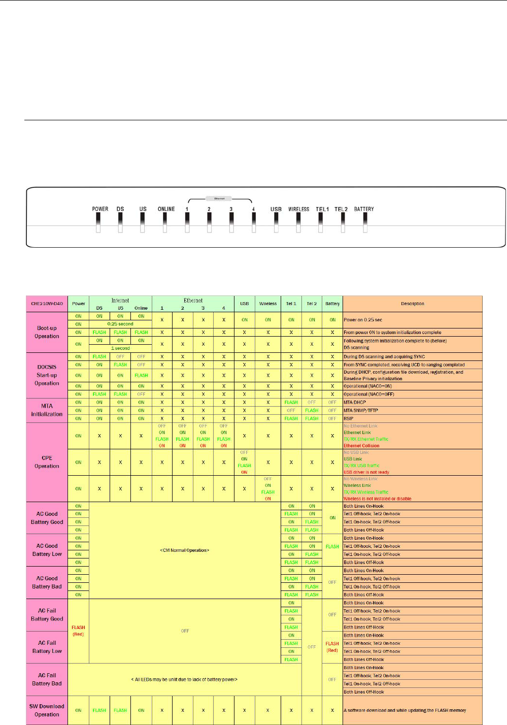
The following illustration shows the front panel of the CABLE MODEM machine:
LED Indicators
The LEDs on the front panel are described in the table below (from left to right):
1
Cable Modem User’s Manual
R
Re
ea
ar
r
P
Pa
an
ne
el
l
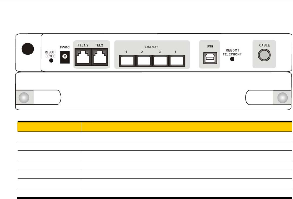
Connector Description
REBOOT DEVICE Reset-to-Default configuration push button
15VDC DC-IN Power connector
TEL1/2 & TEL2 Telephony RJ-11 connector
Ethernet 1-4 Ethernet 10/100BaseT RJ-45 connector
USB USB connector
Reboot Telephony Reboot the VIOP function push button
CABLE F-Connector
2

Chapter 2: Installation
C
Ch
ha
ap
pt
te
er
r
2
2:
:
I
In
ns
st
ta
al
ll
la
at
ti
io
on
n
This cable modem equips USB, wireless and Ethernet interfaces. You can choose either one to connect to the cable
modem. Go to the “Installation Procedure for Ethernet Interface” section, if your computer has installed TCP/IP and
Ethernet card with 10/100BaseT capability. Go to the section “Installation Procedure for USB Interface”, if your PC
has USB port and the operating system is Microsoft Windows 98/ME/XP or Windows 2000.
Note: You don’t need to do installation for wireless interface.
Installation Procedure for Ethernet Interface
Follow the steps below for proper installation:
1. Connect a coaxial cable (supplied by the local Cable Television Company) to the CABLE connector on the
modem.
Note: To speed up the registration process of cable modem, the coaxial cable should be
connected to the modem prior to the power connector.
2. Connect the RJ-45 Ethernet cable to one of the ETHERNET connector on the modem, connect the other end
with the 10/100BaseT Ethernet port on your computer.
3. Plug the power adapter into the POWER connector of the modem.
4. Plug the other end of the power adapter into a power outlet.
5. The cable modem will look for the proper cable modem signal in the Cable Television network and process the
initial registration. The cable modem is ready for data transfer after the LED “CABLE” is in solid green.
Note: The Reset button at the rear panel is for maintenance purpose only.
3
Cable Modem User’s Manual
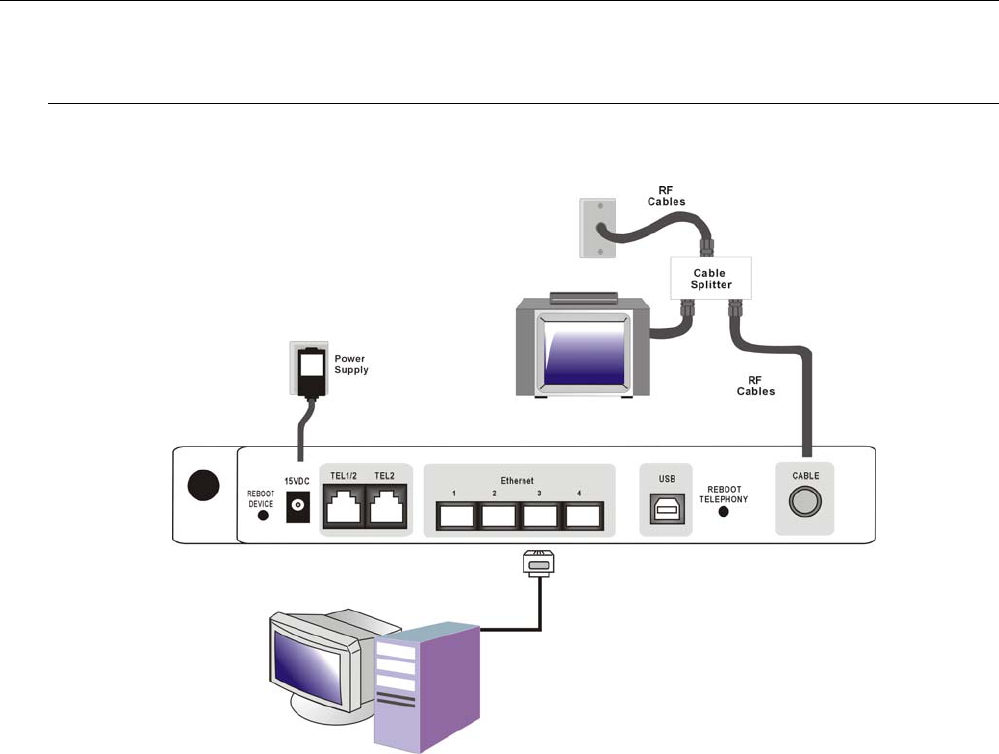
Connecting the Cable Modem to Your Computer
Below shows the connection between the Cable Modem and your computer.
Connection
4
Chapter 2: Installation
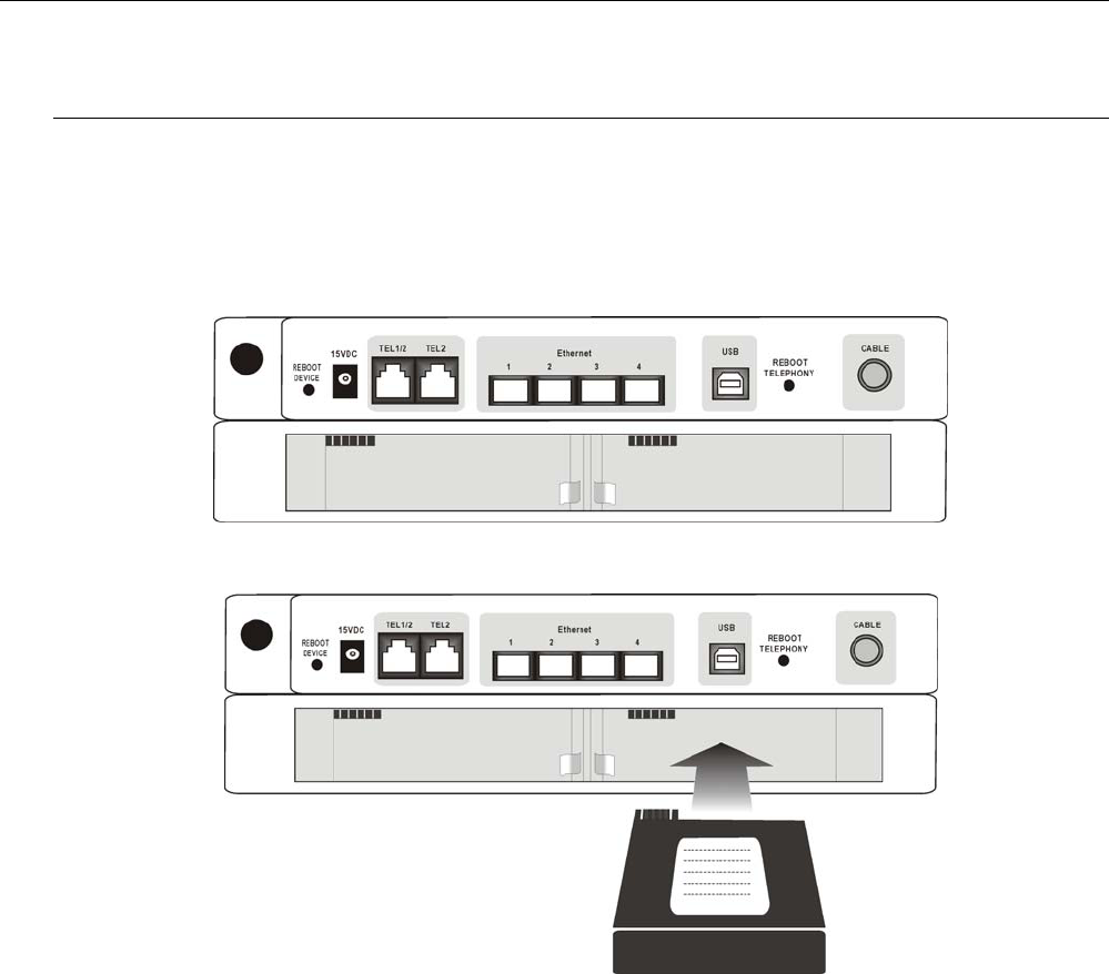
Installing the Battery
This section provides information on installing batteries into the EMTA. Follow the steps below:
1. Ensure the power cord is unplugged.
2. Remove the battery cover on the rear panel. There are two battery compartments. You may install a
single battery into either compartment.
3. Insert the battery into one of the rear battery compartments, as shown below.
4. Reattach the battery cover.
5. Plug the power cord into an AC-recepticle that is always ON (non-switchable). It’s best to secure the plug to the
wall plate using an extended wall plate screw. The battery will fully charge within 4 hours.
5
Cable Modem User’s Manual
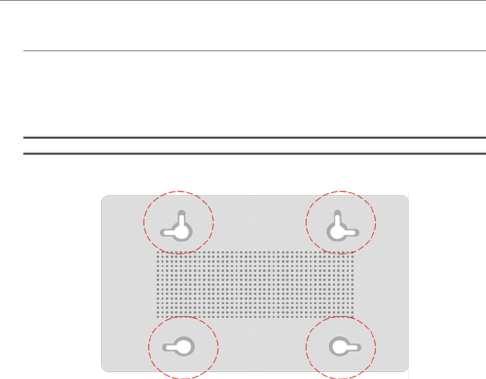
Wall Mounting
The number of the screw: 2 pcs
Direction for wall mounting: LED panel upward.
Dimension for the screw: TBD
There are 2 slots on the underside of the Cable Modem and 4 slots on the underside of the Battery Pack that can be
used for wall mounting.
Note: When wall mounting the unit, ensure that it is within reach of the power outlet.
You will need 2 suitable screws which screw diameter would be 4.4 mm to wall mount the Cable Modem or the
Battery Pack. Two different wall mount directions could be chosen for the Battery Pack.
To do this:
1. For the Cable Modem, ensure that the wall you use is smooth, flat, dry and sturdy and use the 2 screws holes
which both are 101.6 mm apart.
2. For the Battery Pack, ensure that the wall you use is smooth, flat, dry and sturdy and use the 2 screws holes
which both are 101.6 mm or 152.0 mm apart for two different mount directions.
3. Fix the screws into wall, leaving their heads 3 mm (0.12 inch) clear of the wall surface.
4. Remove any connections to the unit and locate it over the screw heads. When in line, gently push the unit on
to the wall and move it downwards to secure.
6

Chapter 3: Software Installation and Configuration
C
Ch
ha
ap
pt
te
er
r
3
3:
:
S
So
of
ft
tw
wa
ar
re
e
I
In
ns
st
ta
al
ll
la
at
ti
io
on
n
a
an
nd
d
C
Co
on
nf
fi
ig
gu
ur
ra
at
ti
io
on
n
Setting TCP/IP on Client PC
After you successfully complete the network interface card (Ethernet card) installation task, you need to make sure
the TCP/IP communications protocol used by the Ethernet card is installed and correctly configured on your system.
F
Fo
or
r
W
Wi
in
nd
do
ow
ws
s
9
98
8/
/9
98
8S
SE
E/
/M
ME
E
1. Click on the Start menu, point to Settings and click on Control Panel.
2. The Control Panel window will show up. Double-click the “Network” icon in the Control Panel window.
3. Windows will appear the Network dialog box. Click “Configuration” tab to bring it to the front, and on this tab,
a list of installed network components appears. Look for an entry that includes TCP/IP-> followed by the
Ethernet card installed in your computer.
4. The Select Network Component Type dialog box will show up. Click ”Protocol”, and then click ”Add”.
5. You will see the Select Network Protocol dialog box. Click “Microsoft” in the “Manufactures:” list, and then
click “TCP/IP” in the “Network Protocols:” list. Click “OK”.
6. You will be directed back to the Network dialog box, and on the “Configuration” tab, the entry that includes
TCP/IP -> followed by the Ethernet card installed in your computer will appear in the list of installed network
components.
7. Click TCP/IP -> followed by the Ethernet card installed in your computer, and then click ”Properties”. The
TCP/IP Properties dialog box will appear.
8. In the TCP/IP Properties dialog box, please follow the directions below: Click “IP Address” tab to bring it to the
front, and then click “Obtain an IP address automatically” on the tab.
9. Click “Gateway” to bring it to the front. On this tab, leave the “New gateway:” blank. If there is the entry in the
“Installed gateway:” list, click it and then click “Remove” to remove all installed gateways.
10. Click “DNS Configuration” tabs to bring it to the front, and click “Disable DNS”, then click “OK” to close the
dialog box.
11. The Copying Files dialog box will pop up and the system will start copying files from Windows. At the first
time you will be asked to insert the Windows 98 CD-ROM (or diskette) into the CD-ROM drive (or floppy
diskette drive) during the files copying, and follow the instructions when they show up, then click “OK”. It will
prompt another Copying Files dialog box. Please type the command line that Windows 98/ME files located in
the dialog box (For example, D:\win98). Click “OK” to continue the files copying.
12. Windows will appear the System Settings Change dialog box and ask you if you would like to restart your
computer. Click “Yes”.
F
Fo
or
r
W
Wi
in
nd
do
ow
ws
s
2
20
00
00
0/
/X
XP
P
1. Click “Start” button on your computer’s taskbar, point to “Settings”, and then click ”Network and Dial-up
Connections”.
2. The Network and Dial-up Connections window will show up. Double-click “Local Area Connection” icon in the
Network and Dial-up Connections window.
3. The Local Area Connection status window will show up. Click the “Properties” button.
4. Click “Internet Protocol (TCP/IP)” and then click “Properties”.
5. The Internet Protocol (TCP/IP) Properties dialog box appears. Click “Obtain an IP address automatically”. Click
“Obtain DNS server address automatically”. Click “OK” to close the dialog box.
6. Windows will appear the System Settings Change dialog box and ask you if you would like to restart your
computer. Click “Yes”.
7

Cable Modem User’s Manual
DHCP Server
PC connected to the cable modem can automatically get a private IP address from the DHCP server of cable modem
before cable modem is on line. The following steps will show you how to get an IP address from DHCP server of
cable modem before cable modem is on line.
F
Fo
or
r
W
Wi
in
nd
do
ow
ws
s
9
98
8/
/9
98
8S
SE
E/
/M
ME
E
1. Click “Start“, point to “Run“, and click to open the “Run“ windows.
2. Enter “winipcfg“ in the “Open“ field. Click “OK“ to execute the winipcfg and show the “IP
Configuration“ window.
3. Select the “Ethernet adapter“ to show the IP address. Press “Release“ and “Renew“ if the PC is not accessing
the Internet. After the cable modem is on line, you need to press the “Release“ and “Renew“ to get a new IP
address from your ISP’s server.
F
Fo
or
r
W
Wi
in
nd
do
ow
ws
s
2
20
00
00
0/
/X
XP
P
1. Click “Start“, point to “Run“, and click to open the “Run“ windows.
2. The Run dialog box appears. Type “cmd” in the “Open” field, and then click “OK” to execute the command.
3. You will enter the dos mode, type “ipconfig”, press “Enter” on your keyboard, and you will see the IP address
your computer get from the cable modem.
4. If PC is not access Internet, type “ipconfig /release”, and press “Enter” on your keyboard to release the IP.
5. Type “ipconfig /renew”, and press “Enter” on your keyboard to renew the IP. You can repeat the steps until your
computer gets the correct IP.
F
Fo
or
r
A
Ap
pp
pl
le
e
M
Ma
ac
ci
in
nt
to
os
sh
h
1. Click “Apple menu“, point to “Control Panels“, and click “TCP/IP” to open the “TCP/IP” window.
2. If the iMac gets an invalid IP, select “Using DHCP Server” in “Configure” field. Click the “Close box” at the
upper left corner to close the “TCP/IP” window.
3. Click the “Save” in the prompted message box.
4. You need to wait about 2 minutes and open “TCP/IP” window to see the new TCP/IP status.
Renew PC IP Address
There is a chance that your PC does not renew its IP address after cable modem is on line and the PC cannot access
the Internet. Please follow the procedures below to renew PC’s IP address after the cable modem is on line.
1. Click “Start“, point to “Run“, and click to open the “Run“ windows.
2. Enter winipcfg in the “Open“ field. Click “OK“ to execute the winipcfg and show the “IP
Configuration“ window.
3. Select the “Ethernet adapter“ to show the IP address. Press “Release“ and “Renew“ to get a new IP address
from your ISP’s server.
4. Select the “OK“ to close the IP Configuration window.
8
Chapter 4: Access Internet through Cable Modem
C
Ch
ha
ap
pt
te
er
r
4
4:
:
A
Ac
cc
ce
es
ss
s
I
In
nt
te
er
rn
ne
et
t
t
th
hr
ro
ou
ug
gh
h
C
Ca
ab
bl
le
e
M
Mo
od
de
em
m
For making sure that you can get into Internet successfully, please make sure the following first.
1. Make sure the connection (through Ethernet) between the cable modem and your computer is OK.
2. Make sure the TCP/IP protocol is set properly.
3. Subscribe to Cable Television Company.
Accessing Internet
Once your host PC is properly configured, please proceed as follows:
1. Start your web browser and type the private IP address of the ADSL Router in the URL field: 192.168.0.1
2. After connecting to the device, you will be prompted to enter username and password. By default, there is no
username and the password is admin.
If you login successfully, the main page will appear. From now on this cable modem acts as a web server sending
HTML pages/forms on your request. You can fill in these pages/forms and apply them to the device.
O
Ou
ut
tl
li
in
ne
e
o
of
f
W
We
eb
b
M
Ma
an
na
ag
ge
er
r
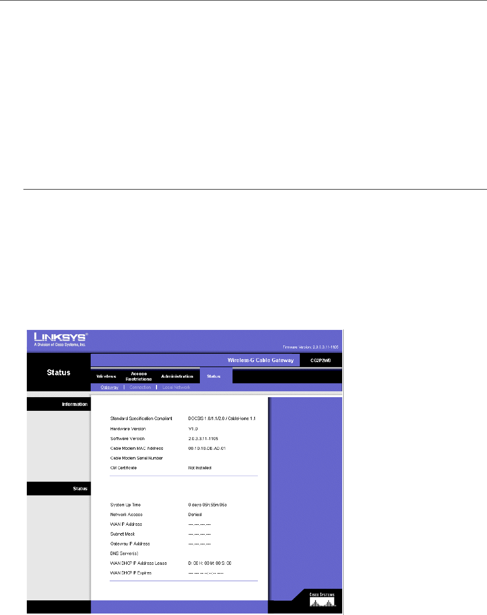
The main screen will be shown as below.
Title: It indicates the title of this management interface.
Main Menu: Includes Wireless, Access Restrictions, Administration and Status
Main Window: It is the current workspace of the web management, containing configuration or status
information.
9
Cable Modem User’s Manual
Wireless
B
Ba
as
si
ic
c
W
Wi
ir
re
el
le
es
ss
s
S
Se
et
tt
ti
in
ng
gs
s
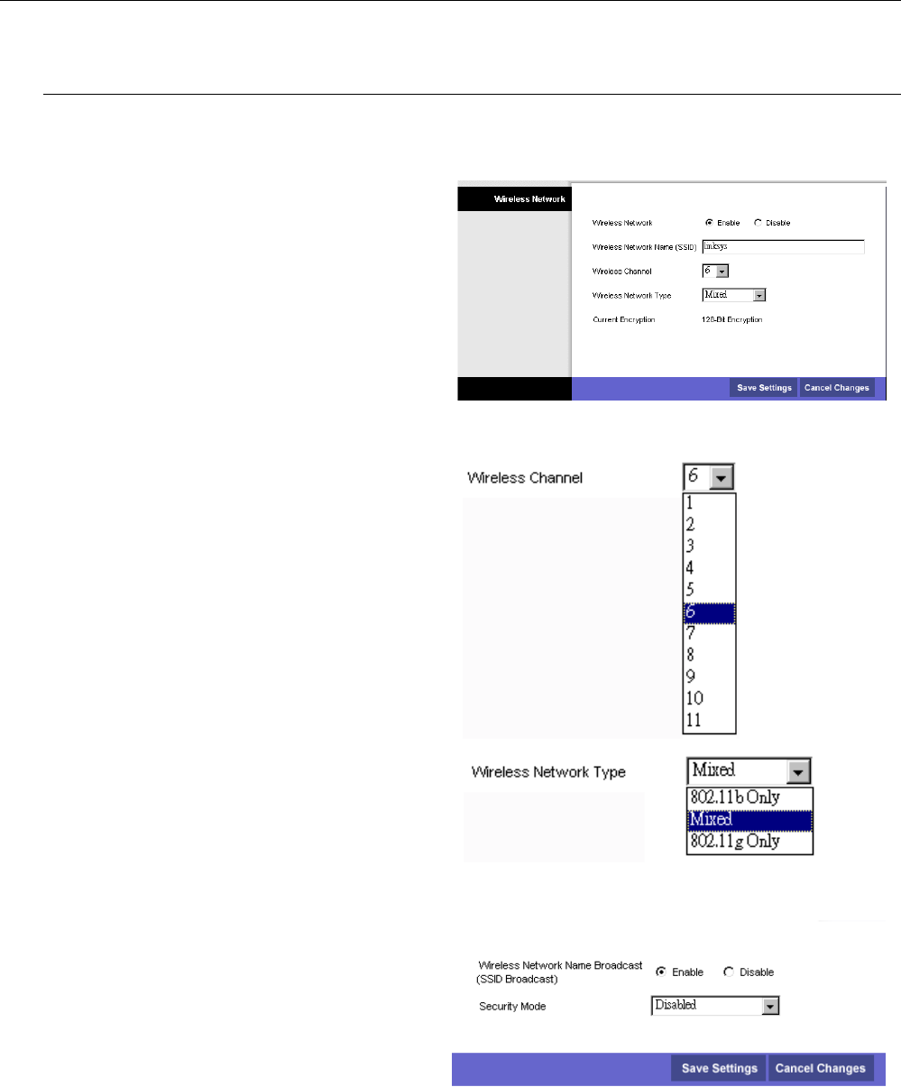
To set the basic configuration for the wireless features, please click Basic item from the Wireless menu.
Wireless Network:
Choose Enabled to enable the basic setting. Choose
Disabled to close the basic setting.
Wireless Network Name(SSID):
The SSID will be displayed automatically.
Wireless Channel:
There are 11 channels that you can choose. Choose
the one that is suitable for this device.
Wireless Network Type:
There are three types that you can choose. Each one
arise different functions for wireless network.
Current Encryption:
It shows the data encryption mode. For the basic
settings, there is no data encryption mode selected.
After you have finished all the settings, please click
Save Settings. It you click Cancel Changes, all the
settings that you have adjusted will not be saved.
W
Wi
ir
re
el
le
es
ss
s
S
Se
ec
cu
ur
ri
it
ty
y
-
-
D
Di
is
sa
ab
bl
le
ed
d
For the disabled wireless security, there is no settings
that you need to adjust. It means your network does
not protect by any security that this router offered.
After finished settings, click Save Settings for
activation for next time.
10
Chapter 4: Access Internet through Cable Modem
W
Wi
ir
re
el
le
es
ss
s
S
Se
ec
cu
ur
ri
it
ty
y
-
-
W
WE
EP
P
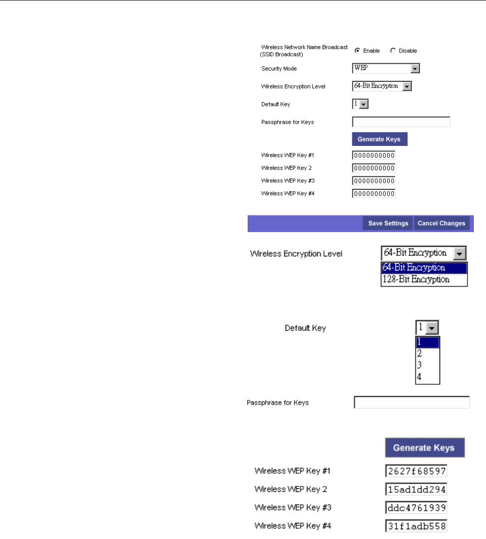
For this mode, the settings that you can adjust
including wireless encryption level, default key,
passphrase for keys, wireless wep key #1 to #4.
Wireless Encryption Level:
Select the WEP mode for the WEP key function. You
can choose 64-bit or 128-bit for your necessity. If
you choose Off, the Encryption Keys will not be
shown on this page. If selected, data is encrypted
using the key before being transmitted. For example,
if you set 128-bit in this field, then the receiving
station must be set to use 128 Bit Encryption, and
have the same Key value too. Otherwise, it will not
be able to decrypt the data.
Default Key:
Select one of network key (from 1 to 4) that you set
on the Key boxes as default one.
PassPhrase for Keys:
You can type in ASCII codes into this field. The
range is from 8 characters to 64 characters. For
ASCII characters, you can type in 63 characters
in this field. If you want to type in 64 characters,
only hexadecimal characters can be used.
Generate WEP Keys:
Click this button to generate the PassPhrase.
Wireless WEP Key #1 to #4:
Type the encryption key length and fill out WEP
keys. The system allows you to type in 4 kinds of the
WEP key. For 64-bit WEP mode, the number you
can type is that 5 characters or 10 hexadecimal digits.
As for 128-bit WEP mode, the number you can type
is that 13 characters or 26 hexadecimal digits.
After finished settings, click Save Settings for
activation for next time.
11
Cable Modem User’s Manual
W
Wi
ir
re
el
le
es
ss
s
S
Se
ec
cu
ur
ri
it
ty
y
-
-
R
Ra
ad
di
iu
us
s
For this mode, the settings that you can adjust
including RADIUS Server, RADIUS Port, and
RADIUS Key.
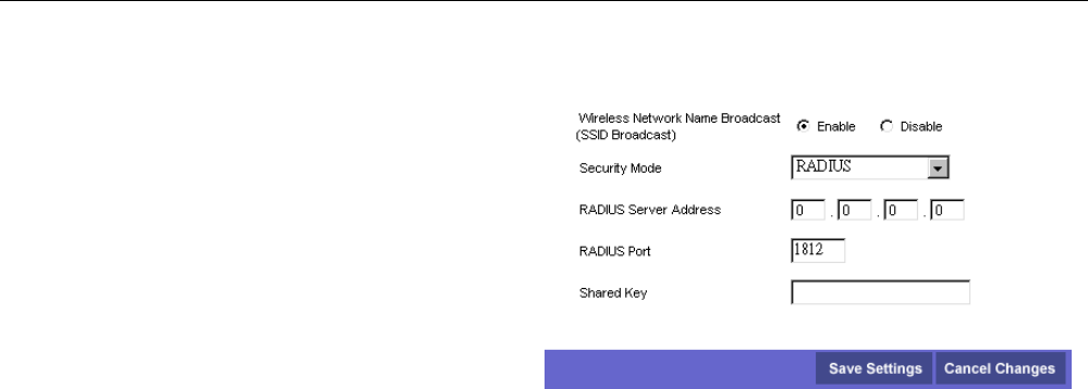
RADIUS Server Address: RADIUS Server is a
protocol for carrying authentication, authorization,
and configuration information between a Network
Access Server which desires to authenticate its links
and a shared Authentication Server. Please type in the
IP Address for the RADIUS Server.
RADIUS Port: Except for the IP address of the
RADIUS Server, you have to enter the port number
for the server. Port 1812 is the reserved
RADIUS-authentication port described in RFC 2138.
Earlier AP (RADIUS clients) use port 1945. The
default value will be shown on this box. You can
keep and use it.
Shared Key: A Shared Key is like a password,
which is used between IAS and the specific RADIUS
client to verify identity. Both IAS and the RADIUS
client must be use the same Shared for successful
communication to occur. Type in the words for the
Shared Key.
After finished settings, click Save Settings for
activation for next time.
12
Chapter 4: Access Internet through Cable Modem
W
Wi
ir
re
el
le
es
ss
s
S
Se
ec
cu
ur
ri
it
ty
y
–
–
W
WP
PA
A
R
RA
AD
DI
IU
US
S
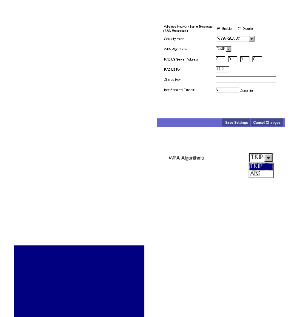
For the WPA network Authentication, the settings
that you can adjust including WPA Algorithms,
RADIUS Server Address, RADIUS Port, Shared key,
Key Renewal Timeout.
WPA Algorithms: Select the data encryption for the
WPA mode. There are two types that you can choose,
TKIP and AES.
RADIUS Server Address: RADIUS Server is a
protocol for carrying authentication, authorization,
and configuration information between a Network
Access Server which desires to authenticate its links
and a shared Authentication Server. Please type in the
IP Address for the RADIUS Server.
RADIUS Port: Except for the IP address of the
RADIUS Server, you have to enter the port number
for the server. Port 1812 is the reserved
RADIUS-authentication port described in RFC 2138.
Earlier RADIUS clients use port 1945. The default
value will be shown on this box. You can keep and
use it.
Shared Key: A Shared Key is like a password,
which is used between IAS and the specific RADIUS
client to verify identity. Both IAS and the RADIUS
client must be use the same Shared for successful
communication to occur. Type in the words for the
Shared Key.
Key Renewal Timeout: Type in the time for the
WAP group rekey interval. The unit is second.
TKIP takes the original master key only as a
starting point and derives its encryption keys
mathematically from this mater key. Then it
regularly changes and rotates the encryption keys
so that the same encryption key will be never used
twice.
AES provides security between client
workstations operating in ad hoc mode. It uses a
mathematical ciphering algorithm that employs
variable key sizes of 128, 192 or 256 bits.
After finished settings, click Save Settings for
activation for next time.
13
Cable Modem User’s Manual
W
Wi
ir
re
el
le
es
ss
s
S
Se
ec
cu
ur
ri
it
ty
y
–
–
W
WP
PA
A
P
Pr
re
e-
-S
Sh
ha
ar
re
ed
d
K
Ke
ey
y
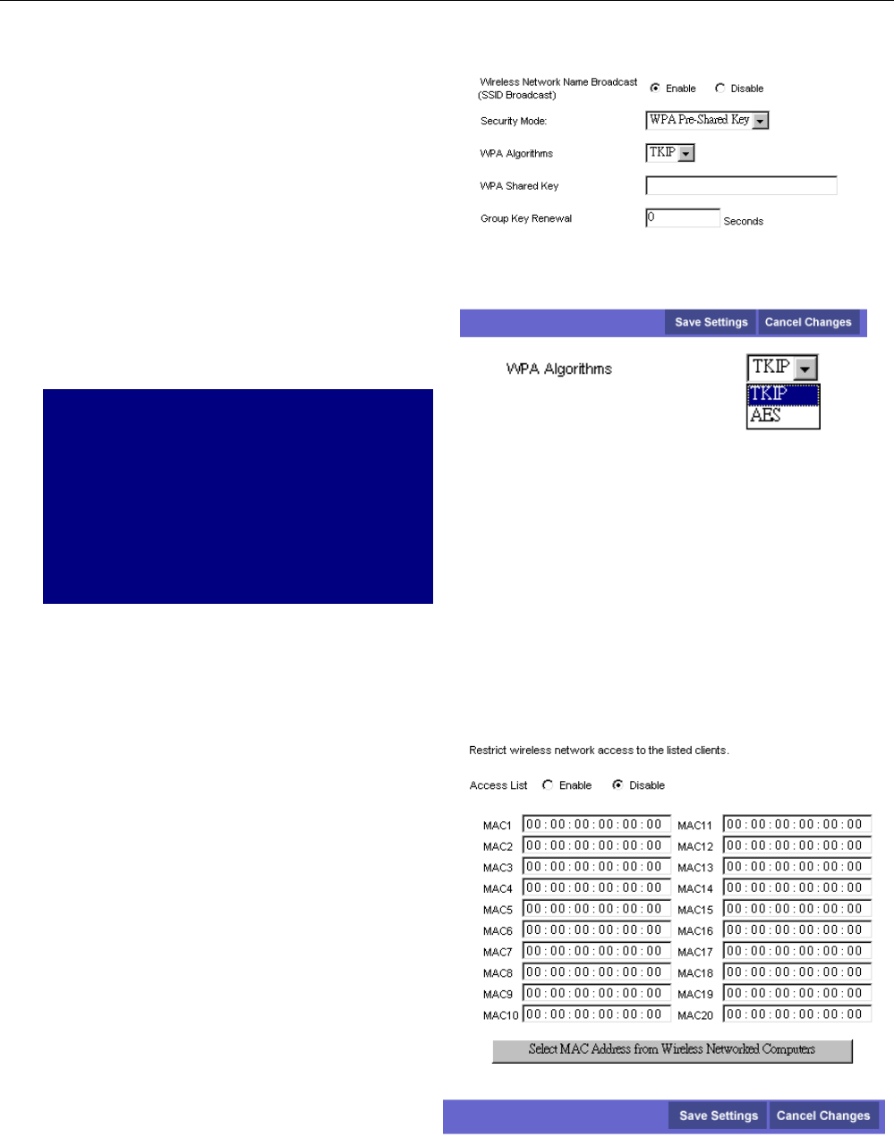
For the WPA-PSK mode, the settings that you can
adjust including WPA Algorithms, WPA Shared Key
and Group Key Renewal.
WPA Algorithms: Select the data encryption for the
WPA mode. There are three types that you can
choose, TKIPand AES.
WPA Shared Key: Please type the key to be
between 8 and 63 characters, or 64 hexadecimal
digits. Only the devices with a matching key that you
set here can join this network.
Group key Renewal: Type in the time for the WAP
group rekey interval. The unit is second.
TKIP takes the original master key only as a
starting point and derives its encryption keys
mathematically from this mater key. Then it
regularly changes and rotates the encryption keys
so that the same encryption key will be never used
twice.
AES provides security between client
workstations operating in ad hoc mode. It uses a
mathematical ciphering algorithm that employs
variable key sizes of 128, 192 or 256 bits.
After finished settings, click Save Settings for
activation for next time.
W
Wi
ir
re
el
le
es
ss
s
N
Ne
et
tw
wo
or
rk
k
A
Ac
cc
ce
es
ss
s
It allows you to set control to the AP and the connected clients.
Access List:
Click Enabled to enable this function; click Disabled
to close this function.
MAC Address:
Type in the MAC address of the AP or connected
clients into this field as an allowed or denied device.
Select MAC Address from Wireless Network
Computers:
Click this button to get the connected clients’ MAC
address.
14

Chapter 4: Access Internet through Cable Modem
The information of connected clients will be
displayed in this field if its MAC address is typed
above.
A
Ad
dv
va
an
nc
ce
ed
d
W
Wi
ir
re
el
le
es
ss
s
S
Se
et
tt
ti
in
ng
gs
s
The Advanced wireless setting allows you to
configure the data rates and WiFi thresholds.
Basic Data Rates:
Choose Minimal or All as the basic rates.
Control TX Rate:
Choose Minimal or All as the supported rates.
Beacon Interval:
Set the period of beacon transmissions to allow
mobile stations to locate and identify a BSS. The
measure unit is “time units”(TU) of 1024
microseconds.
DTIM Interval:
The value you set here are used to inform mobile
stations when multicast frames that have been
buffered at the router will be delivered and how often
that delivery will happen.
Fragmentation Threshold:
Set the number of the fragmenting frames to make
the data be delivered without errors induced by the
interference.
Frames longer than the value you set here are
fragmented prior to the initial transmission into
fragments no longer than the value of the threshold.
RTS Threshold:
Set the value for sending a request to the destination.
All the frames of a length greater than the threshold
that you set here will be sent with the four-way frame
exchange. And, a length less than or equal to the
value that you set will not be preceeded by RTS.
Authentication Type:
It decides the authentication type will be activated as
open system function or shared key function.
15
Cable Modem User’s Manual
Access Restrictions
There are restrictions that you have to notice for access into the network.
W
We
eb
bs
si
it
te
e
B
Bl
lo
oc
ck
ki
in
ng
g
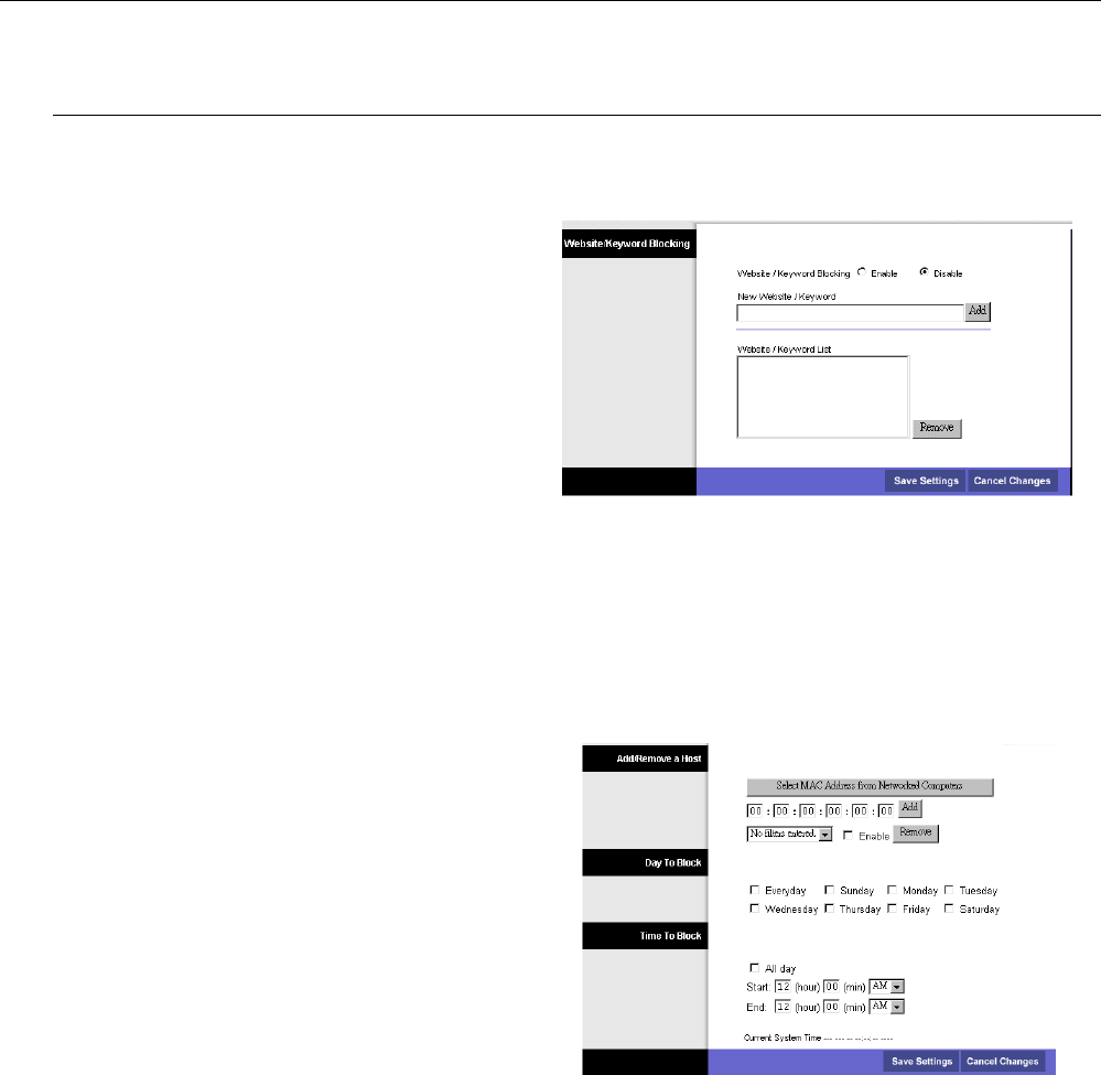
Website/keyword Blocking:
Click Enable to activate this function; click Disable
to close this function.
New Website/Keyword:
Some websites/web pages that you do not want them
to be shown or appeared while you are surfing the
Internet, can be blocked by typing the website name
or using the words that you typed here in their
webpages. Please type in the website/words in the
box and click Add. The new one will be shown on the
Website/Keyword List to tell the system the web
page with this work cannot access into.
Website/Keyword List:
It shows the words you type in the above box. If you
want to delete any word here, simple choose that
word to make it inverse, and click Remove. The web
site/word will be deleted immediately.
T
Ti
im
me
e
A
Ac
cc
ce
es
ss
s
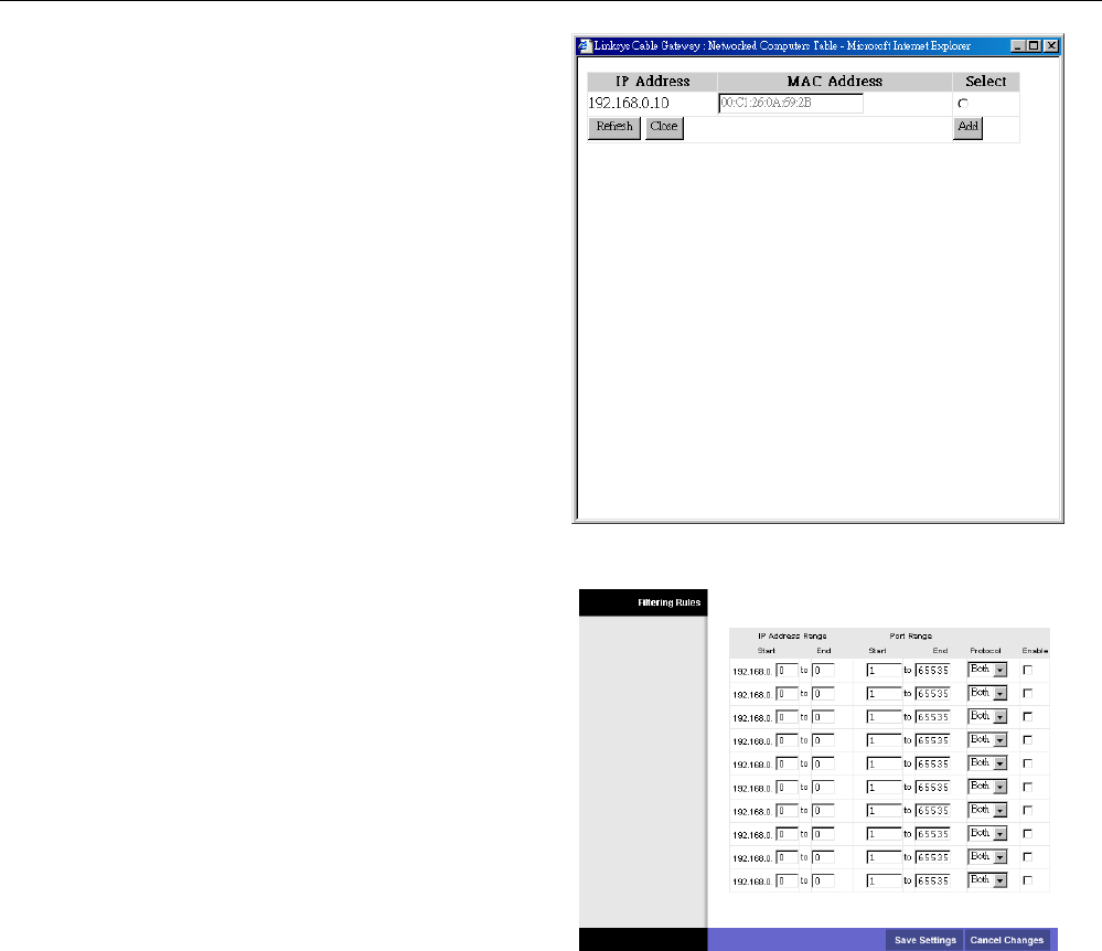
Select MAC Address from Networked Computers:
If you do not want to type the host address by
yourself, you can use this button to select any one
which is shown in the dialog box.
Add:
Type in the MAC address in these boxes, and click
Add. The new one will be added and be shown on the
drop down list below.
Remove:
If you do want to remove any added MAC address,
please choose the one from the drop down list and
click this button.
Day to Block:
Choose the day that you want the block function to
be activated.
Time to Block:
To make a whole day block, please choose All day.
And type in the start and end time in the
corresponding boxes.
Current System Time:
It will show current time if it is invoked.
16
Chapter 4: Access Internet through Cable Modem
This dialog shows the networked computer that your
computer can choose for executing time access.
F
Fi
il
lt
te
er
r
I
In
nt
te
er
rn
ne
et
t
T
Tr
ra
af
ff
fi
ic
c
IP Address Range Start to End:
You have to tell the system the start point and end
point for the filter internet traffic used. Type in the
number from 0 to 256 in these fields.
Port Range:
The default setting for port range is from 1 to 65535.
You don’t need to change it.
Protocol:
Select one of the protocols for using in this function.
Enable:
Click enable to activate this function. If you do not
check this item, the function will not be activated
even if you have made some decisions.
17
Cable Modem User’s Manual
Administration
S
Se
ec
cu
ur
ri
it
ty
y
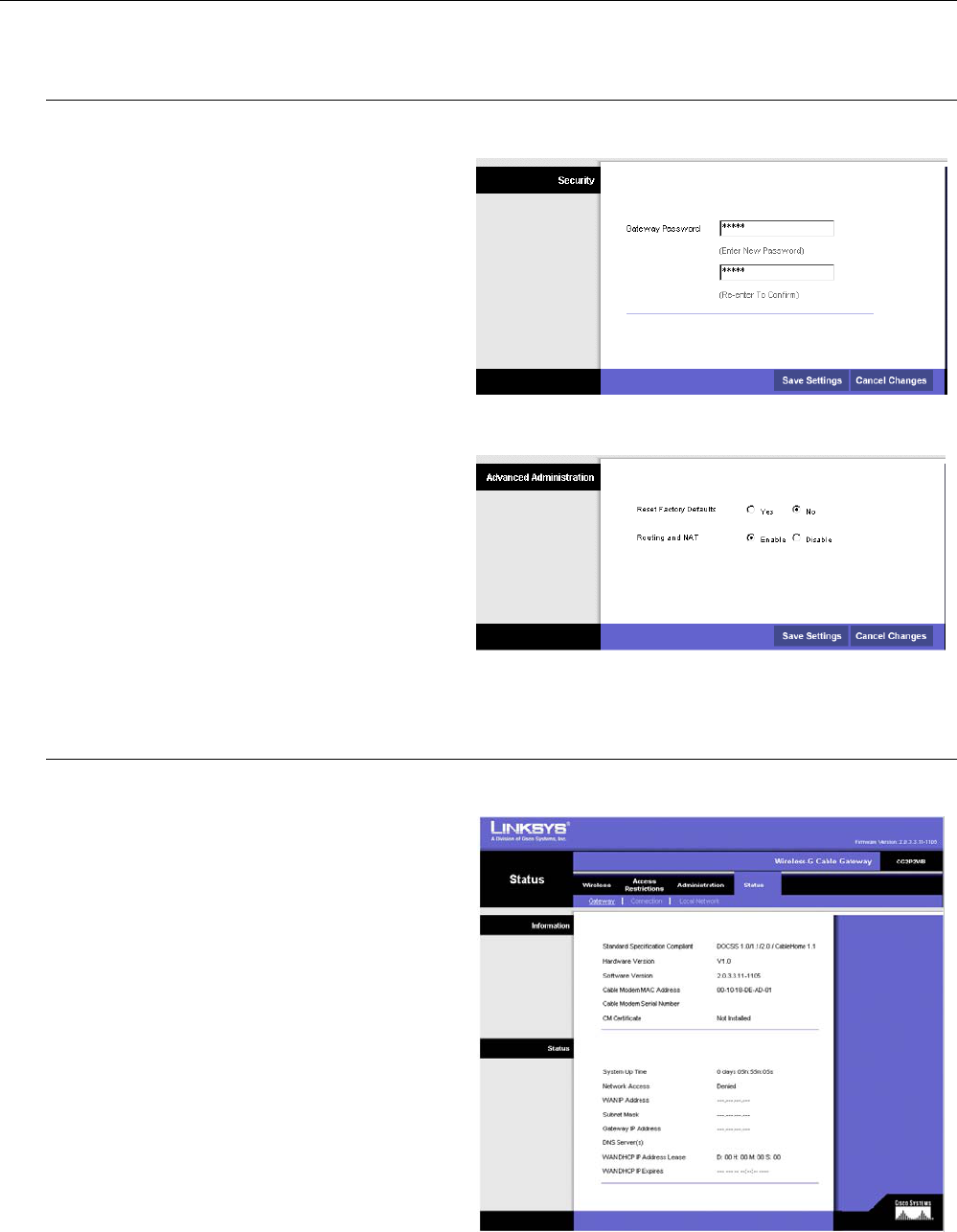
Gateway Password:
Please type in the password for the gateway. And
then retype in the below field again.
Click Save Settings to save the configuration.
A
Ad
dv
va
an
nc
ce
ed
d
A
Ad
dm
mi
in
ni
is
st
tr
ra
at
ti
io
on
n
Reset Factory Default:
Click Yes to use the factory default after restart this
device. Click No to use current settings that you just
configured. This function is useful when you adjust
the other settings in disorder.
Routing and NAT:
Click Enable to invoke this function; click Disable
to close this function.
Click Save Settings to save the configuration.
Status
G
Ga
at
te
ew
wa
ay
y
This page shows the software information containing
the standard specification compliant, software
version, and so on.
18
Chapter 4: Access Internet through Cable Modem
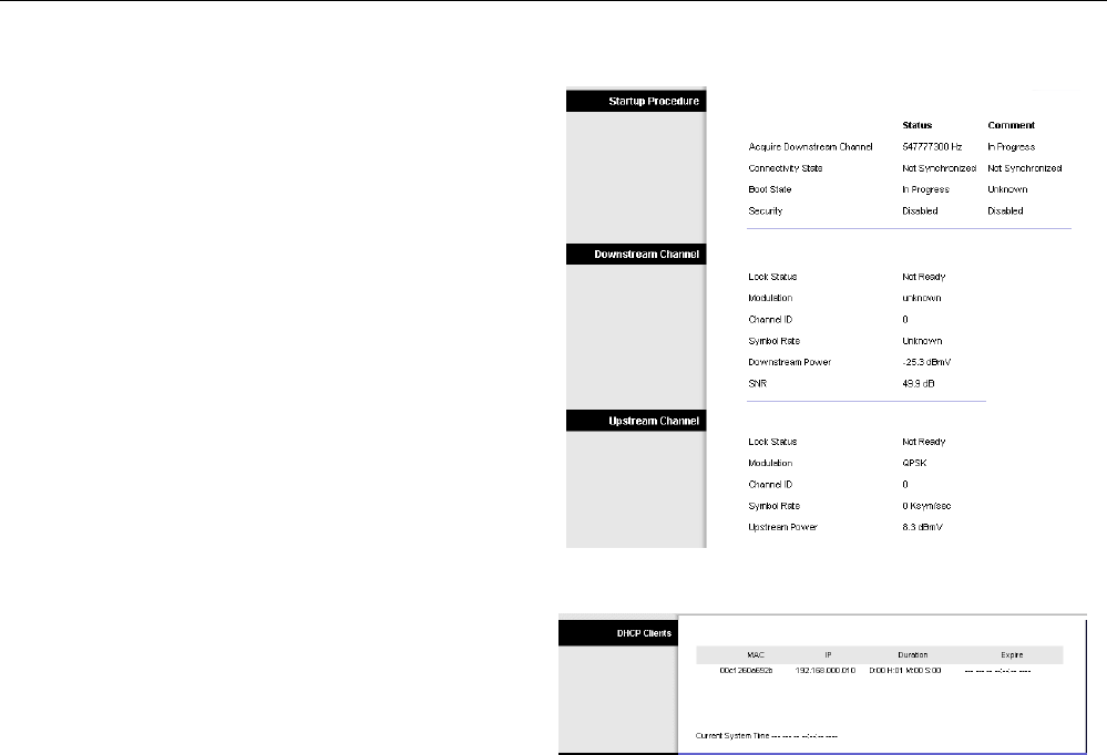
C
Co
on
nn
ne
ec
ct
ti
io
on
n
This page shows current connection status containing
upstream channel, downstream channel, and startup
procedure.
L
Lo
oc
ca
al
l
N
Ne
et
tw
wo
or
rk
k
This page shows the local network information for
your reference.
19

Cable Modem User’s Manual
20

Chapter 5: Troubleshooting
C
Ch
ha
ap
pt
te
er
r
5
5:
:
T
Tr
ro
ou
ub
bl
le
es
sh
ho
oo
ot
ti
in
ng
g
If the suggested solutions in this section do not resolve your issue, contact your system administrator or Internet
service provider.
Can I use the same cable line for TV and cable modem?
A. Yes, the TV and cable modem uses the cable line. You need a splitter to use them at the same time. Ask Cable
Company to install the splitter for you to avoid signal degradation.
My cable modem cannot get a solid green light on the Status LED when I connect
the cable back.
A. The cable modem lost the signal during the disconnection period and it will keeps scanning other available signal.
When you connect the cable back, it might take a while to find the correct channel. You can power cycle the
modem to speedup the process since modem will remember the channel last time and it will start from that
channel at startup.
Which port of the Ethernet hub should I connect to the modem if I need to connect
multiple PC to the modem?
A. You should connect the modem to the up-link port of the hub. The link LED of the hub will be on.
How do I see my IP address?
A. If you are using Windows 95/98/ME, the winipcfg command will show you to IP address of the PC connected to
the cable modem. Notice that even though you seem get the same address all the time, it may still be a dynamic
address.
Can I just connect the cable modem and two computers to a hub?
A. Yes. You need to make sure you can get two IP addresses from your cable modem service provider. Connect the
modem to the up-link port of the hub.
I have a cable modem. How can I make it work?
A. Basically, modem is plug and play. You can just connect the modem and you are ready to go if you have the
subscription. For ensure good signal for your cable modem, you should ask your cable provider to install the
cable modem for you.
Can I switch between a notebook and PC using the same cable modem? Will there
be a problem to obtain a DHCP IP address?
A. This issue depends on how your cable modem service provider manages the modems. If you are using one of the
cable modem service providers that register your PC based on the MAC address of the Ethernet card in the PC,
then you will have to call them and have them change that entry every time you switch between the two. Ask
them if you have problem on this issue.
21