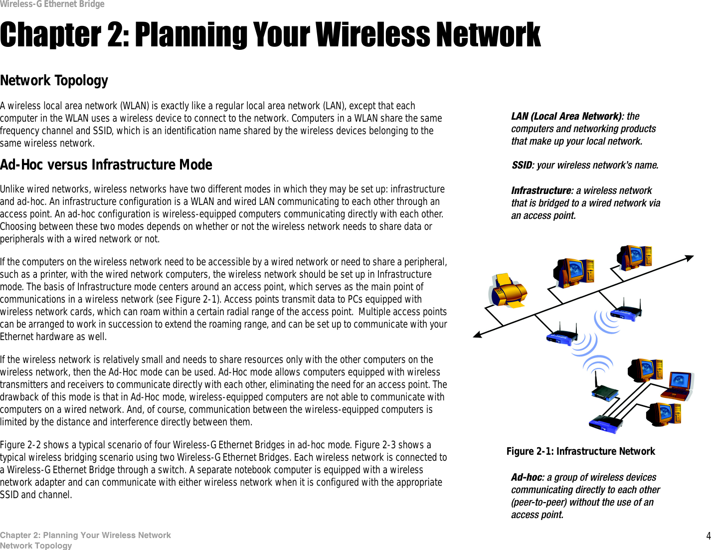
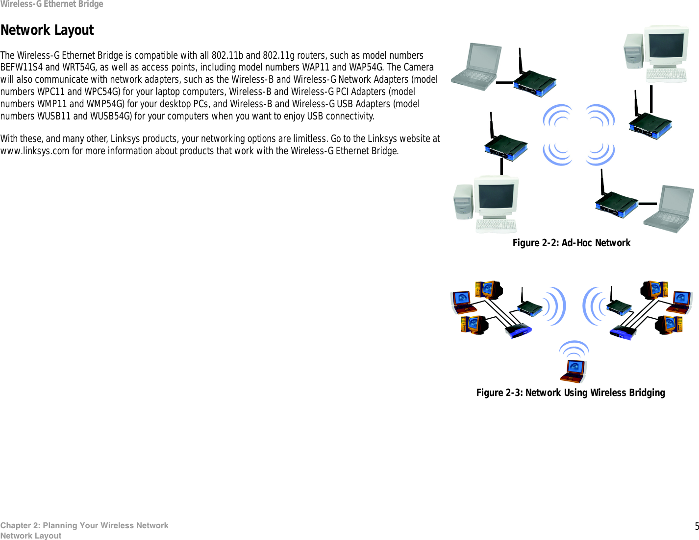
LINKSYS WET54GS5 Wireless-G Ethernet Bridge with 5-Port Switch User Manual Book

LINKSYS LLC Wireless-G Ethernet Bridge with 5-Port Switch Book

Contents

user manual part 1

A Division of Cisco Systems, Inc.®Model No.Ethernet BridgeWireless-GWET54GS5User GuideWIRELESSGHz2.4802.11g
Wireless-G Ethernet BridgeCopyright and TrademarksSpecifications are subject to change without notice. Linksys is a registered trademark or trademark of Cisco Systems, Inc. and/or its affiliates in the U.S. and certain other countries. Copyright © 2004 Cisco Systems, Inc. All rights reserved. Other brands and product names are trademarks or registered trademarks of their respective holders. How to Use this GuideYour guide to the Wireless-G Ethernet Bridge has been designed to make understanding networking with the Wireless-G Ethernet Bridge easier than ever. Look for the following items when reading this guide:In addition to these symbols, there are definitions for technical terms that are presented like this:Also, each figure (diagram, screenshot, or other image) is provided with a figure number and description, like this:Figure numbers and descriptions can also be found in the “List of Figures” section in the “Table of Contents”.This exclamation point means there is a Caution or warning and is something that could damage your property or the Wireless-G Ethernet Bridge.word: definition.This checkmark means there is a Note of interest and is something you should pay special attention to while using the Wireless-G Ethernet Bridge.This question mark provides you with a reminder about something you might need to do while using the Wireless-G Ethernet Bridge.Figure 0-1: Sample Figure DescriptionWET54GS5-UG-403011A BW
Wireless-G Ethernet BridgeTable of ContentsChapter 1: Introduction 1Welcome 1What’s in this Guide? 2Chapter 2: Planning Your Wireless Network 4Network Topology 4Network Layout 5Chapter 3: Getting to Know the Wireless-G Ethernet Bridge 6The Back Panel 6The Front Panel 7Chapter 4: Connecting the Wireless-G Ethernet Bridge for Setup 8Chapter 5: Setting Up the Wireless-G Ethernet Bridge 9Chapter 6: Connecting the Wireless-G Ethernet Bridge for Network Use 14Connection to a Network Device 14Placement Options 14Chapter 7: Using the Wireless-G Ethernet Bridge Web-based Utility 16Overview 16Starting the Web-based Utility 16Setup 17Password 24Advanced Settings 24Status 26Help 27Appendix A: Troubleshooting 28Common Problems and Solutions 28Frequently Asked Questions 29Appendix B: Wireless Security 32Security Precautions 32Security Threats Facing Wireless Networks 32Appendix C: Upgrading Firmware 35Appendix D: Windows Help 36
Wireless-G Ethernet BridgeAppendix E: Glossary 37Appendix F: Specifications 43Appendix G: Warranty Information 45Appendix H: Regulatory Information 46Appendix I: Contact Information 48
Wireless-G Ethernet BridgeList of FiguresFigure 2-1: Infrastructure Network 4Figure 2-2: Ad-Hoc Network 5Figure 2-3: Network Using Wireless Bridging 5Figure 3-1: Back Panel 6Figure 3-2: Front Panel 7Figure 4-1: Connect to the Network 8Figure 4-2: Connect the Power 8Figure 5-1: Welcome 9Figure 5-2: Connection 9Figure 5-3: List of Bridges 10Figure 5-4: Password 10Figure 5-5: Mode Settings 10Figure 5-6: Wireless Settings 11Figure 5-7: IP Settings 11Figure 5-8: Security Settings-WEP 12Figure 5-9: Security Settings-WPA-PSK 12Figure 5-10: Confirmation 13Figure 5-11: Congratulations 13Figure 6-1: Horizontal Placement 14Figure 6-2: Vertical Placement 15Figure 7-1: Password Screen 16Figure 7-2: Setup Tab 17Figure 7-3: Site Survey 18Figure 7-4: Security Settings 18Figure 7-5: WEP 19Figure 7-6: WPA Pre-Shared Key 20Figure 7-7: Log Table 20Figure 7-8: RADIUS-MD5 21Figure 7-9: RADIUS-TLS 22
Wireless-G Ethernet BridgeFigure 7-10: RADIUS-TTLS 23Figure 7-11: Password Tab 24Figure 7-12: Advanced Settings Tab 24Figure 7-13: Status Tab 26Figure 7-14: Help Tab 27Figure 7-15: Firmware Upgrade 27Figure C-1: Firmware Upgrade 35
1Chapter 1: IntroductionWelcomeWireless-G Ethernet BridgeChapter 1: IntroductionWelcomeThank you for choosing the Wireless-G Ethernet Bridge. The versatile Wireless-G Ethernet Bridge can make any wired Ethernet-equipped device a part of your wireless network. At home, use the Bridge to connect game consoles, set-top boxes, or computers to your Wireless-G network and its shared high-speed Internet connection.  In the office, convert your Ethernet-wired printer, camera, notebook or desktop into a wireless networked device.It's completely driver-free, so it works on any platform and under any operating system! Since there's no drivers to load, setup is a snap—configure the network settings through your PC's web browser, then plug it into your device and go.  And physical installation is simplified by support for Power Over Ethernet. With an optional POE Adapter, you can mount the Bridge wherever you want—power and data are both supplied through the Category 5 Ethernet cable.You can also use the Wireless-G Ethernet Bridge as a kind of “cable-less cable” to connect remote areas together. Maybe Shipping is all the way across the warehouse from Receiving. Or maybe you want to set up a home office in your detached garage.  With a Wireless-G Ethernet Bridge in the garage, and another one (or a Wireless-G Access Point) in the house, you're connected—no digging trenches, and no overhead wires. Let the Wireless-G Ethernet Bridge from Linksys open up exciting new possibilities for your wireless network.Use the instructions in this Guide to help you set up and connect the Bridge. These instructions should be all you need to get the most out of the Wireless-G Ethernet Bridge.Ethernet: an IEEE standard network protocol that specifies how data is placed on and retrieved from a common transmission medium.802.11g: an IEEE wireless networking standard that specifies a maximum data transfer rate of 54Mbps, an operating frequency of 2.4GHz, and backward compatibility with 802.11b devices.
2Chapter 1: IntroductionWhat’s in this Guide?Wireless-G Ethernet BridgeWhat’s in this Guide?This user guide covers the steps for setting up and using the Wireless-G Ethernet Bridge.• Chapter 1: IntroductionThis chapter describes the Wireless-G Ethernet Bridge applications and this user guide.• Chapter 2: Planning your Wireless NetworkThis chapter describes the basics of wireless networking.• Chapter 3: Getting to Know the Wireless-G Ethernet BridgeThis chapter describes the physical features of the Bridge.• Chapter 4: Connecting the Wireless-G Ethernet Bridge for Setup.This chapter instructs you on how to connect the Bridge to your network for setup.• Chapter 5: Setting Up the Wireless-G Ethernet Bridge.This chapter explains how to set up the Bridge using the Setup Wizard.• Chapter 6: Connecting the Wireless-G Ethernet Bridge for Network Use.This chapter explains how to connect the Bridge to a network device so the device can join your wireless network. It also describes placement options for the Bridge.• Chapter 7: Using the Wireless-G Ethernet Bridge Web-based UtilityThis chapter explains how to use the Web-based Utility so you can change the Bridge’s settings or advanced configuration.• Appendix A: TroubleshootingThis appendix describes some problems and solutions, as well as frequently asked questions, regarding installation and use of the Wireless-G Ethernet Bridge.• Appendix B: Wireless SecurityThis appendix explains the risks of wireless networking and some solutions to reduce the risks.• Appendix C: Upgrading FirmwareThis appendix instructs you on how to upgrade the firmware on the Bridge should you need to do so.• Appendix D: Windows HelpThis appendix describes how you can use Windows Help for instructions about networking, such as installing the TCP/IP protocol.
3Chapter 1: IntroductionWhat’s in this Guide?Wireless-G Ethernet Bridge• Appendix E: GlossaryThis appendix gives a brief glossary of terms frequently used in networking.• Appendix F: SpecificationsThis appendix provides the technical specifications for the Bridge.• Appendix G: Warranty InformationThis appendix supplies the warranty information for the Bridge.• Appendix H: Regulatory InformationThis appendix supplies the regulatory information regarding the Bridge.• Appendix I: Contact InformationThis appendix provides contact information for a variety of Linksys resources, including Technical Support.
4Chapter 2: Planning Your Wireless NetworkNetwork TopologyWireless-G Ethernet BridgeChapter 2: Planning Your Wireless NetworkNetwork TopologyA wireless local area network (WLAN) is exactly like a regular local area network (LAN), except that each computer in the WLAN uses a wireless device to connect to the network. Computers in a WLAN share the same frequency channel and SSID, which is an identification name shared by the wireless devices belonging to the same wireless network.Ad-Hoc versus Infrastructure ModeUnlike wired networks, wireless networks have two different modes in which they may be set up: infrastructure and ad-hoc. An infrastructure configuration is a WLAN and wired LAN communicating to each other through an access point. An ad-hoc configuration is wireless-equipped computers communicating directly with each other. Choosing between these two modes depends on whether or not the wireless network needs to share data or peripherals with a wired network or not. If the computers on the wireless network need to be accessible by a wired network or need to share a peripheral, such as a printer, with the wired network computers, the wireless network should be set up in Infrastructure mode. The basis of Infrastructure mode centers around an access point, which serves as the main point of communications in a wireless network (see Figure 2-1). Access points transmit data to PCs equipped with wireless network cards, which can roam within a certain radial range of the access point.  Multiple access points can be arranged to work in succession to extend the roaming range, and can be set up to communicate with your Ethernet hardware as well. If the wireless network is relatively small and needs to share resources only with the other computers on the wireless network, then the Ad-Hoc mode can be used. Ad-Hoc mode allows computers equipped with wireless transmitters and receivers to communicate directly with each other, eliminating the need for an access point. The drawback of this mode is that in Ad-Hoc mode, wireless-equipped computers are not able to communicate with computers on a wired network. And, of course, communication between the wireless-equipped computers is limited by the distance and interference directly between them. Figure 2-2 shows a typical scenario of four Wireless-G Ethernet Bridges in ad-hoc mode. Figure 2-3 shows a typical wireless bridging scenario using two Wireless-G Ethernet Bridges. Each wireless network is connected to a Wireless-G Ethernet Bridge through a switch. A separate notebook computer is equipped with a wireless network adapter and can communicate with either wireless network when it is configured with the appropriate SSID and channel.SSID: your wireless network’s name.LAN (Local Area Network): the computers and networking products that make up your local network.Figure 2-1: Infrastructure NetworkInfrastructure: a wireless network that is bridged to a wired network via an access point.Ad-hoc: a group of wireless devices communicating directly to each other (peer-to-peer) without the use of an access point.
5Chapter 2: Planning Your Wireless NetworkNetwork LayoutWireless-G Ethernet BridgeNetwork LayoutThe Wireless-G Ethernet Bridge is compatible with all 802.11b and 802.11g routers, such as model numbers BEFW11S4 and WRT54G, as well as access points, including model numbers WAP11 and WAP54G. The Camera will also communicate with network adapters, such as the Wireless-B and Wireless-G Network Adapters (model numbers WPC11 and WPC54G) for your laptop computers, Wireless-B and Wireless-G PCI Adapters (model numbers WMP11 and WMP54G) for your desktop PCs, and Wireless-B and Wireless-G USB Adapters (model numbers WUSB11 and WUSB54G) for your computers when you want to enjoy USB connectivity.With these, and many other, Linksys products, your networking options are limitless. Go to the Linksys website at www.linksys.com for more information about products that work with the Wireless-G Ethernet Bridge. Figure 2-3: Network Using Wireless BridgingFigure 2-2: Ad-Hoc Network
6Chapter 3: Getting to Know the Wireless-G Ethernet BridgeThe Back PanelWireless-G Ethernet BridgeChapter 3: Getting to Know the Wireless-G Ethernet BridgeThe Back PanelAll connections to the Bridge are made through the ports on its back panel, shown in Figure 3-1.Reset When pressed, the Reset button resets the Bridge to its factory default settings.LAN The LAN port is where you will connect the Ethernet network cable.Power The Power port is where you will connect the power adapter.Important: If you reset the Wireless-G Ethernet Bridge, you will erase all of your settings (WEP encryption, wireless settings, etc.) and replace them with the factory defaults. Do not reset the Wireless-G Ethernet Bridge if you want to retain these settings.NOTE: If you use a Power over Ethernet (PoE) device to supply data and power through the Ethernet network cable, then you do not need to use the Power port.
7Chapter 3: Getting to Know the Wireless-G Ethernet BridgeThe Front PanelWireless-G Ethernet BridgeThe Front PanelThe LEDs indicate network activity experienced by the Bridge. (See Figure 3-2.)Power Green. The Power LED will light up when the Bridge is powered on. While the Bridge is booting up and performing a self-test, the Power LED will flash. It will stop flashing and remain lit when the self-test has ended.Ethernet Green. The Ethernet LED will be lit steadily when the Bridge is connected to the wired network. The LED will flash when there is wired network traffic.Wireless-G Green. The Wireless-G LED will be lit steadily when the Bridge is connected to the wireless network. The LED will flash when there is wireless network traffic.
8Chapter 4: Connecting the Wireless-G Ethernet Bridge for SetupWireless-G Ethernet BridgeChapter 4: Connecting the Wireless-G Ethernet Bridge for Setup1. Attach the Bridge’s antenna.2. Plug the included Ethernet network cable into the LAN port on the back panel of the Bridge, shown in Figure 4-1.3. Plug the other end of the Ethernet network cable into the RJ-45 port of the hub, switch, or PC you wish to use to configure the Bridge.4. Plug the supplied power cable into the Power port on the back panel of the Bridge, shown in Figure 4-2. Then plug the other end into an electrical outlet. Proceed to “Chapter 5: Setting Up the Wireless-G Ethernet Bridge.”
9Chapter 5: Setting Up the Wireless-G Ethernet BridgeWireless-G Ethernet BridgeChapter 5: Setting Up the Wireless-G Ethernet BridgeNow that you’ve connected the Wireless-G Ethernet Bridge to your wired network, you are ready to set it up. The Setup Wizard will guide you through all the necessary steps. 1. Insert the Setup CD-ROM into your PC’s CD-ROM drive. The Setup Utility should run automatically, and the screen in Figure 5-1 should appear. If it does not, click the Start button and choose Run. In the field that appears, enter D:\setup.exe (if “D” is the letter of your CD-ROM drive).• Setup - Click the Setup button to proceed with the Setup Wizard. • User Guide - Click the User Guide button to open the PDF file of this User Guide. • LINKSYS Web - Click the LINKSYS Web button to access the Linksys website using an active Internet connection.• Exit - Click the Exit button to exit the Setup Wizard.2. Click the Setup button to begin the setup process.3. Make sure the Bridge is correctly connected to your wired network (see Figure 5-2). Then click the Next button.Note: While the Wireless-G Ethernet Bridge has been designed to work correctly right out of the box, setting it up on a wireless computer will require you to use the Linksys default settings (SSID: linksys and mode: infrastructure). These settings can then be changed through the Bridge’s Setup Wizard or Web-based Utility.
10Chapter 5: Setting Up the Wireless-G Ethernet BridgeWireless-G Ethernet Bridge4. The screen shown in Figure 5-3 displays a list of Wireless-G Ethernet Bridges on your network, along with the status information for each Bridge. (If you have only one Bridge on your network, it will be the only one displayed.) Select the Bridge you are currently installing by clicking its name in the Selection box. Write down the IP address of the Wireless-G Ethernet Bridge, so you can use it to access the Web-based Utility later. Then click the Yes button.5. For security purposes, you will be asked for your password in order to access the Bridge, as shown in Figure 5-4. In lowercase letters, enter admin in the Password field (later you can change the password through the Web-based Utility). Then click the Enter button.6. The screen shown in Figure 5-5 shows a choice of two wireless modes. Click the Infrastructure radio button if you want your wireless computers to network with computers on your wired network using a wireless access point. Click the Ad-Hoc radio button if you want multiple wireless computers to network directly with each other. Do not use the Ad-Hoc mode if you want to network your wireless computers with computers on your wired network. In the WB Name field, enter a unique name for the Bridge. Memorable names are helpful, especially if you are using multiple bridges on the same network. Click the Next button to continue or the Back button to return to the previous screen.Figure 5-4: PasswordFigure 5-3: List of BridgesFigure 5-5: Mode Settings
11Chapter 5: Setting Up the Wireless-G Ethernet BridgeWireless-G Ethernet Bridge7. The Wireless Settings screen, shown in Figure 5-6, will now appear. Enter your wireless network’s SSID. If you chose Ad-Hoc mode, select the channel at which the network broadcasts its wireless signal. If you have Wireless-G (802.11g) and Wireless-B (802.11b) devices in your network, then keep the default Network Mode setting, Mixed. If you have only Wireless-G devices, select G-Only. Then click the Next button to continue or the Back button to return to the previous screen. • SSID - The SSID is the unique name shared among all devices in a wireless network. The SSID must be identical for all devices in the wireless network. It is case-sensitive and must not exceed 32 alphanumeric characters, which can be any keyboard character.• Channel - From the drop-down menu, select the appropriate channel to match your network settings (available for Ad-Hoc mode only). All devices in your wireless network must use the same channel in order to communicate.• Network Mode - Keep the default setting, Mixed, if you have Wireless-G and Wireless-B devices in your network. Select G-Only if you have only Wireless-G devices in your network.8. The IP Settings screen will appear next, shown in Figure 5-7. If your network has a DHCP server, click the radio button next to Automatically obtain an IP address (DHCP). Click the Next button to continue or the Back button to return to the previous screen. Then proceed to step 9.If your network does not have a DHCP server, click the radio button next to Set IP configuration manually to select this option. Enter an IP Address, IP Mask, and Gateway appropriate to your network. You must specify an IP address on this screen. If you are unsure about the IP Mask and Gateway, it is better to leave these two fields blank. Click the Next button to continue or the Back button to return to the previous screen. Then proceed to step 9.• IP Address - This IP address must be unique to your network.• IP Mask - The Bridge’s IP Mask (also known as Subnet Mask) must be the same as your wired network’s Subnet Mask.• Gateway - Enter the IP address of your network’s Gateway (usually this is your router’s IP address).Figure 5-7: IP SettingsFigure 5-6: Wireless Settings
12Chapter 5: Setting Up the Wireless-G Ethernet BridgeWireless-G Ethernet Bridge9. The Security Settings (Optional) screen, shown in Figure 5-8, appears next. From the drop-down menu, select one of the wireless security mode options supported by the Bridge: WPA PSK (Pre-Shared Key) and WEP. (WPA stands for Wi-Fi Protected Access, which is a security standard stronger than WEP encryption. WEP stands for Wired Equivalent Privacy. If you do not want to use the security function, keep the default setting, Disabled. The security modes are briefly discussed below. For more detailed instructions on configuring wireless security for the Bridge, refer to “Appendix B: Wireless Security.”WEP (64-bit WEP/128-bit WEP) - In order to utilize WEP encryption, select 64-bit or 128-bit WEP from the drop-down menu. Then, enter a Passphrase. (If you want to enter a WEP key manually, leave the Passphrase field blank, and complete the Key 1 field.) Click the Next button to continue.• Passphrase - Instead of manually entering a WEP key, you can enter a Passphrase, so a WEP key will be automatically generated. The Passphrase is case-sensitive and should have 16 or fewer alphanumeric characters. It must match the passphrase of your wireless network and is compatible with Linksys wireless products only. (You will have to enter the WEP key(s) manually on any non-Linksys wireless products.If you want to manually enter a WEP key, leave the Passphrase field blank and complete the Key 1 field.• Key 1 - If you entered a Passphrase, then you will see the automatically generated WEP key. Click the Next button, and proceed to step 10.If you did not enter a Passphrase, then enter a WEP key in the Key 1 field. If you are using 64-bit WEP encryption, then the key must consist of exactly 10 hexadecimal characters. If you are using 128-bit WEP encryption, then the key must consist of exactly 26 hexadecimal characters. Valid hexadecimal characters are “0”-“9” and “A”-“F”. Then click the Next button, and proceed to step 10.WPA PSK - In order to utilize WPA PSK, select WPA PSK from the drop-down menu. WPA PSK gives you one encryption method, TKIP, with dynamic encryption keys. Select the type of algorithm, TKIP, then enter a Pre-Shared Key of 8-32 characters. (See Figure 5-9.)Figure 5-8: Security Settings-WEPFigure 5-9: Security Settings-WPA-PSK
13Chapter 5: Setting Up the Wireless-G Ethernet BridgeWireless-G Ethernet Bridge10. Review your settings on the Confirmation screen, shown in Figure 5-10. Write down the Bridge’s IP Address if you want to configure advanced settings through the Bridge’s Web-based Utility. Click the Yes button to save these settings. Click the No button to exit the Setup Wizard.11. The next screen, shown in Figure 5-11, shows that the configuration is complete. To configure any other Wireless-G Ethernet Bridges on your network, run this Setup Wizard again. To register the Bridge, click the Online Registration button. To exit the Setup Wizard, click the Exit button.The Wireless-G Ethernet Bridge is now successfully configured for your network. For advanced configuration, proceed to “Chapter 7: Using the Wireless-G Ethernet Bridge Web-based Utility.” Otherwise, go to “Chapter 6: Connecting the Wireless-G Ethernet Bridge for Network Use.”Figure 5-10: Confirmation
14Chapter 6: Connecting the Wireless-G Ethernet Bridge for Network UseConnection to a Network DeviceWireless-G Ethernet BridgeChapter 6: Connecting the Wireless-G Ethernet Bridge for Network UseConnection to a Network Device1. After configuration, unplug the power cable from the electrical outlet, and unplug the Ethernet network cable from the PC. 2. Plug the Ethernet network cable into the RJ-45 port on the Ethernet-ready network device you wish to add to the wireless network. 3. Plug the power cable into a local electrical outlet.The installation of the Wireless-G Ethernet Bridge is complete. Proceed to the next section, “Placement Options,” if you want to mount the Bridge on a wall or have the Bridge stand on a surface.Placement OptionsThere are three ways to place the Bridge. The first way is to place the Bridge horizontally on a surface, as shown in Figure 6-1. (If necessary, adjust the antenna so that it points straight up in the air.) The second way is to hang the Bridge on a wall, with the Bridge in a vertical position. The third way is to stand the Bridge vertically on a surface. The second and third options are explained in further detail below.Wall Mount Option1. The Bridge has eight rubber inserts, four on each side. Depending on how you want to mount the Bridge, remove two of the rubber inserts.2. Attach two screws to the wall, so that the Bridge’s wall-mount slots line up with the two screws.3. Maneuver the Bridge so the screws are inserted into the two slots. 4. If necessary, adjust the antenna so that it points straight up in the air. The installation of the Wireless-G Ethernet Bridge is complete.Note: The Bridge features Power Over Ethernet (PoE) support. PoE technology allows a PoE adapter (also known as a power injector, power hub, or inline power device) to supply data and power to an Ethernet device using a single Ethernet network cable. To use the Bridge’s PoE feature, follow the instructions for your specific PoE device.
15Chapter 6: Connecting the Wireless-G Ethernet Bridge for Network UsePlacement OptionsWireless-G Ethernet BridgeStand Option1. The Bridge has eight rubber inserts, four on each side. Remove the two rubber inserts that are adjacent to the power port.2. The Bridge includes two triangular stands. Insert a stand into an opening. Push the stand up to snap it into place.3. Repeat step 2 using the second stand.4. Place the Bridge in an appropriate location.5. If necessary, adjust the antenna so that it points straight up in the air. (See Figure 6-2.)The installation of the Wireless-G Ethernet Bridge is complete.
16Chapter 7: Using the Wireless-G Ethernet Bridge Web-based UtilityOverviewWireless-G Ethernet BridgeChapter 7: Using the Wireless-G Ethernet Bridge Web-based UtilityOverviewThe Bridge is designed to function properly after you configure it using the Setup Wizard. However, if you would like to change these basic settings or make advanced configuration changes, use your web browser and the Wireless-G Ethernet Bridge Web-based Utility. This chapter explains how to use the Utility.Starting the Web-based Utility1. Open your web browser, and enter the IP address of the Wireless-G Ethernet Bridge (the default is 192.168.1.226). Press the Enter key, and the screen shown in Figure 7-1 will appear. In lowercase letters, enter the default password, admin, in the Password field. Click the OK button. You can set a new password on the Password screen later.2. The Utility’s Setup screen, shown in Figure 7-2, will appear. The Utility provides a convenient, web-browser-based way to alter the Bridge’s settings. It offers five main tabs:• Setup - Enables you to configure the IP address and wireless settings.• Password - Allows you to change the password or reset all settings to factory defaults.• Advanced - Lets you change the advanced wireless settings and clone a MAC address onto the Bridge.• Status - Displays the Bridge’s current settings.• Help - Provides explanations of various configuration settings and links to online technical support resources. You can also upgrade the Bridge’s firmware using the Help screen.Have You:  Enabled TCP/IP on your PCs? PCs communicate over the network with this protocol. Refer to “Appendix D: Windows Help” for more information on TCP/IP.Note: The Wireless-G Ethernet Bridge is designed to function properly after you use the Setup Wizard. However, if you would like to change its basic settings or make advanced configuration changes, use your web browser and the Wireless-G Ethernet Bridge Web-based Utility. Figure 7-1: Password Screen
17Chapter 7: Using the Wireless-G Ethernet Bridge Web-based UtilitySetupWireless-G Ethernet BridgeSetupThe Setup screen, shown in Figure 7-2, lets you configure the wired and wireless network settings for the Bridge.• Firmware - The version number of the Bridge’s firmware is displayed here. Firmware should be upgraded ONLY if you experience problems with the Bridge. Firmware updates are posted at www.linksys.com.• MAC Address - The MAC Address of the Bridge is displayed here.LAN• Device Name - You may assign any name to the Bridge. Unique, memorable names are helpful, especially if you are using multiple bridges on the same wireless network.• Configuration Type - If the Bridge will obtain an IP address automatically from a DHCP server, such as a router, then select Automatic Configuration-DHCP. If you are assigning the Bridge a static IP address, then select Static IP Address, and enter an IP Address, Subnet Mask, and Gateway address in the IP Address, Subnet Mask, and Gateway fields. Wireless• SSID - The SSID is the network name shared among all devices in a wireless network. The SSID must be identical for all devices in the wireless network. It is case-sensitive and must not exceed 32 alphanumeric characters, which may be any keyboard character (do not use any spaces). Make sure this setting is the same for all devices in your wireless network. For added security, Linksys recommends that you change the default SSID (linksys) to a name of your choice.To search for available wireless networks, click the Site Survey button.• Network Type - Choose a wireless operating mode for the Bridge. Keep the default setting, Infrastructure, if you want your wireless-equipped device to communicate with computers and other devices on your wired network using a wireless access point. Select Ad-Hoc button if you want multiple wireless-equipped devices to communicate directly with each other. If you chose Ad-Hoc mode, then select the correct operating channel for your network from the Channel drop-down menu. This should match the channel setting of the other devices in your wireless network.Select the appropriate network mode. Keep the default, Mixed, if you have Wireless-G (802.11g) and Wireless-B (802.11b) devices in your network. Select G-Only if you have only Wireless-G devices in your network.Figure 7-2: Setup Tab
18Chapter 7: Using the Wireless-G Ethernet Bridge Web-based UtilitySetupWireless-G Ethernet Bridge• Wireless Site SurveyThe Wireless Site Survey screen, shown in Figure 7-3 shows all the wireless networks detected by the Bridge and their general information. You can use this screen to connect to one of these networks.For each wireless network detected, the following information is displayed:• SSID - The network name. To join a wireless network, click its SSID.• MAC Address - The MAC address of the network’s access point.• Channel - The channel setting.• Signal Strength (%) - The percentage of wireless signal strength.• Mode - The type of wireless standard, network mode, and status of WEP encryption.Click the Refresh button to obtain the most up-to-date data. Click the Cancel button to close this screen. Click the Help button for additional on-screen information.• SecuritySecurity - To enable security, select Enable, then click Edit Security Settings. If you have not enabled security before clicking on Edit Security Settings, the screen in Figure 7-4 will appear. To disable security, select Disable. To save your changes, click the Apply button. Click the Cancel button to cancel your changes. Click the Help button for additional on-screen information.Figure 7-3: Site SurveyNOTE: Make sure that your security choice matches the security choice of the wireless network you want to join. Otherwise, the connection will fail.Figure 7-4: Security Settings
19Chapter 7: Using the Wireless-G Ethernet Bridge Web-based UtilitySetupWireless-G Ethernet BridgeIf you click Edit Security Settings, The Security screen, as shown in Figure 7-5, will appear. From the drop-down menu, select one of the four wireless security modes supported by the Bridge: WPA Pre-Shared Key, WPA RADIUS, RADIUS, and WEP. (WPA stands for Wi-Fi Protected Access, which is a security standard stronger than WEP encryption. WEP stands for Wired Equivalent Privacy, while RADIUS stands for Remote Authentication Dial-In User Service) .The four security modes are briefly discussed here. For detailed instructions on configuring wireless security for the Bridge, turn to “Appendix B: Wireless Security.”WEPUse the WEP screen, shown in Figure 7-5, to configure the WEP encryption for the Bridge. Select a Default Transmit Key (choose which Key to use), and a level of WEP Encryption, 64 bits (10 hex digits) or (128 bits 26 hex digits). Then either generate a WEP Key using a Passphrase or enter the WEP key manually. • Default Transmit Key - Select which WEP key (1-4) will be used when the Bridge sends data. Make sure the other wireless-equipped devices are using the same key.• WEP Encryption - In order to use WEP encryption, select 64-Bit (10 hex digits) or 128-Bit (26 hex digits) from the drop-down menu.• Passphrase - Instead of manually entering WEP keys, you can enter a Passphrase. This Passphrase is used to generate one or more WEP keys. It is case-sensitive and should not be longer than 16 alphanumeric characters. (The Passphrase function is compatible with Linksys wireless products only. If you want to communicate with non-Linksys wireless products, you will need to enter your WEP key manually on the non-Linksys wireless products.) After you enter the Passphrase, click the Generate button to create WEP key(s).• Keys 1-4 - If you are not using a Passphrase, then you can enter one or more WEP keys manually.In each key field, manually enter a set of values. (Do not leave a key field blank, and do not enter all zeroes. These are not valid key values.) If you are using 64-bit WEP encryption, then each key must consist of exactly 10 hexadecimal characters in length. If you are using 128-bit WEP encryption, then each key must consist of exactly 26 hexadecimal characters in length. Valid hexadecimal characters are “0”-“9” and “A”-“F”.Click the Apply button to save your changes. If your page doesn’t automatically refresh itself, then click the Refresh button of your web browser. Figure 7-5: WEP
20Chapter 7: Using the Wireless-G Ethernet Bridge Web-based UtilitySetupWireless-G Ethernet BridgeWPA Pre-Shared KeyWPA gives you TKIP for the encryption method. Enter a WPA Shared Key of 8-32 characters. (See Figure 7-6.) Enter a key shared between the Bridge and the server. Click the Apply button to save your changes. If your page doesn’t automatically refresh itself, then click the Refresh button of your web browser. Click the View Log button to view a log.The Log Table screen appears in Figure 7-7. The log shows the authentication process. Click the Refresh button to refresh the screen. Click the Close button to return to the the previous screen.Figure 7-7: Log TableFigure 7-6: WPA Pre-Shared Key
21Chapter 7: Using the Wireless-G Ethernet Bridge Web-based UtilitySetupWireless-G Ethernet BridgeRADIUSThis option features WEP used in coordination with a RADIUS server. (This should only be used when a RADIUS server is connected to the Router.) It offers three authentication methods: MD5, TLS, and TTLS.EAP TypeMD5Select a Default Key (choose which Key to use), and a level of WEP encryption, 64 bits 10 hex digits or 128 bits 26 hex digits. Then either generate a WEP key using a Passphrase or enter the WEP key manually. (See Figure 7-8.)• Default Transmit Key  Select which WEP key (1-4) will be used when the Bridge sends data. Make sure that the receiving device (wireless client) is using the same key.• WEP Encryption. An acronym for Wired Equivalent Privacy, WEP is an encryption method used to protect your wireless data communications. WEP uses 64-bit or 128-bit keys to provide access control to your network and encryption security for every data transmission. To decode data transmissions, all devices in a network must use an identical WEP key. Higher encryption levels offer higher levels of security, but due to the complexity of the encryption, they may decrease network performance. Select 64 bits (10 hex digits) or 128 bits (26 hex digits).• Passphrase. Instead of manually entering WEP keys, you can enter a passphrase. This passphrase is used to generate one or more WEP keys. It is case-sensitive and should not be longer than 32 alphanumeric characters. (This Passphrase function is compatible with Linksys wireless products only and cannot be used with Windows XP Zero Configuration. If you want to communicate with non-Linksys wireless products or Windows XP Zero Configuration, make a note of the WEP key generated in the Key 1 field, and enter it manually in the wireless client.) After you enter the Passphrase, click the Generate button to create WEP keys. • Keys 1-4. WEP keys enable you to create an encryption scheme for wireless network transmissions. If you are not using a Passphrase, then manually enter a set of values. (Do not leave a key field blank, and do not enter all zeroes; they are not valid key values.) If you are using 64-bit WEP encryption, the key must be exactly 10 hexadecimal characters in length. If you are using 128-bit WEP encryption, the key must be exactly 26 hexadecimal characters in length. Valid hexadecimal characters are “0”-“9” and “A”-“F”.• User ID and Password. A user identification and password are required for your security. Enter the ID in the User ID field, then the password in the Password field.When finished making your changes on this tab, click the Apply button to save these changes. Figure 7-8: RADIUS-MD5Encryption - Encoding data transmitted in a network.

Navigation menu