LINKSYS WRK54GV2 Wireless-G Broadband Router with 4-Port Switch User Manual Book
LINKSYS LLC Wireless-G Broadband Router with 4-Port Switch Book
LINKSYS >
Contents
- 1. Manual 1
- 2. Manual 2
Manual 1
A Division of Cisco Systems, Inc.
®
Model No.
Broadband Router
Wireless-G
WRK54G
User Guide
WIRELESS
GHz
2.4
802.11g
Wireless-G Broadband Router
Copyright and Trademarks
Specifications are subject to change without notice. Linksys is a registered trademark or trademark of Cisco
Systems, Inc. and/or its affiliates in the U.S. and certain other countries. Copyright © 2005 Cisco Systems, Inc. All
rights reserved. Other brands and product names are trademarks or registered trademarks of their respective
holders.
How to Use This User Guide
This User Guide has been designed to make understanding networking with the Wireless-G Broadband Router
easier than ever. Look for the following items when reading this User Guide:
In addition to these symbols, there are definitions for technical terms that are presented like this:
Also, each figure (diagram, screenshot, or other image) is provided with a figure number and description, like
this:
Figure numbers and descriptions can also be found in the “List of Figures” section in the “Table of Contents”.
This exclamation point means there is a caution or
warning and is something that could damage your
property or the Wireless-G Broadband Router.
This checkmark means there is a note of interest and
is something you should pay special attention to
while using the Wireless-G Broadband Router.
This question mark provides you with a reminder
about something you might need to do while using
the Wireless-G Broadband Router.
word: definition.
Figure 0-1: Sample Figure Description
WRK54G-UG-51019 BW
WARNING: This product contains chemicals, including lead, known
to the State of California to cause cancer, and birth defects or other
reproductive harm. Wash hands after handling.

Wireless-G Broadband Router
Table of Contents
Chapter 1: Introduction 1
Welcome 1
What’s in this User Guide? 2
Chapter 2: Planning Your Wireless Network 4
Network Topology 4
Ad-Hoc versus Infrastructure Mode 4
Network Layout 4
Chapter 3: Getting to Know the Wireless-G Broadband Router 6
The Back Panel 6
The Front Panel 7
Chapter 4: Connecting the Wireless-G Broadband Router 8
Overview 8
Hardware Installation for Connection to Your Broadband Modem 8
Hardware Installation for Connection to Another Router 10
Chapter 5: Configuring the Wireless-G Broadband Router 12
Overview 12
The Setup Tab - Basic Setup 13
The Setup Tab - DDNS 18
The Setup Tab - MAC Address Clone 19
The Setup Tab - Advanced Routing 20
The Wireless Tab - Basic Wireless Settings 21
The Wireless Tab - Wireless Security 22
The Wireless Tab - Wireless MAC Filter 25
The Wireless Tab - Advanced Wireless Settings 26
The Security Tab - Firewall 27
The Security Tab - VPN Passthrough 27
The Access Restrictions Tab - Internet Access 28
The Applications and Gaming Tab - Port Range Forward 30
The Applications & Gaming Tab - Port Triggering 31
The Applications and Gaming Tab - DMZ 32
The Applications and Gaming Tab - QoS 32
The Administration Tab - Management 35

Wireless-G Broadband Router
The Administration Tab - Log 35
The Administration Tab - Diagnostics 36
The Administration Tab - Factory Defaults 37
The Administration Tab - Firmware Upgrade 37
The Administration Tab - Config Management 37
The Status Tab - Router 38
The Status Tab - Local Network 39
The Status Tab - Wireless 39
Appendix A: Troubleshooting 40
Common Problems and Solutions 40
Frequently Asked Questions 48
Appendix B: Wireless Security 55
Security Precautions 55
Security Threats Facing Wireless Networks 55
Appendix C: Upgrading Firmware 58
Appendix D: Windows Help 59
Appendix E: Finding the MAC Address and IP Address for Your Ethernet Adapter 60
Windows 98SE or Me Instructions 60
Windows 2000 or XP Instructions 60
For the Router’s Web-based Utility 61
Appendix F: Glossary 62
Appendix G: Specifications 69
Appendix H: Warranty Information 71
Appendix I: Regulatory Information 72
Appendix J: Contact Information 78

Wireless-G Broadband Router
List of Figures
Figure 3-1: The Router’s Back Panel 6
Figure 3-2: The Router’s Front Panel 7
Figure 4-1: Connecting Your Internet Connection 8
Figure 4-2: Connecting Your Network Devices 9
Figure 4-3: Connecting the Power 9
Figure 4-4: Diagram for Connection to Another Router 10
Figure 4-5: Connecting Another Router 10
Figure 4-6: Connecting Your Network Devices 11
Figure 4-7: Connecting the Power 11
Figure 5-1: Password Screen 12
Figure 5-2: Setup Tab - Basic Setup 13
Figure 5-3: DHCP Connection Type 13
Figure 5-4: Static IP Connection Type 13
Figure 5-5: PPPoE Connection Type 14
Figure 5-6: PPTP Connection Type 14
Figure 5-7: L2TP Connection Type 15
Figure 5-8: Telestra Cable Connection Type 15
Figure 5-9: Optional Settings 16
Figure 5-10: Router IP 16
Figure 5-11: Network Address Server Settings 17
Figure 5-12: Time Setting 17
Figure 5-13: Setup Tab - DDNS - DynDNS account 18
Figure 5-14: Setup Tab - DDNS - TZO account 18
Figure 5-15: Setup Tab - MAC Address Clone 19
Figure 5-16: Setup Tab - Advanced Routing (Gateway) 20
Figure 5-17: Setup Tab - Advanced Routing (Router) 20
Figure 5-18: Wireless Tab - Basic Wireless Settings 21
Figure 5-19: Wireless Tab - Wireless Security (WPA Personal) 22
Figure 5-20: Wireless Tab - Wireless Security (WPA Enterprise) 22
Figure 5-21: Wireless Tab - Wireless Security (WPA2 Personal) 23
Figure 5-22: Wireless Tab - Wireless Security (WPA2 Enterprise) 23

Wireless-G Broadband Router
Figure 5-23: Wireless Tab - Wireless Security (RADIUS) 24
Figure 5-24: Wireless Tab - Wireless Security (WEP) 24
Figure 5-25: Wireless Tab - Wireless MAC Filter 25
Figure 5-26: MAC Address Filter List 25
Figure 5-27: Wireless Tab - Advanced Wireless Settings 26
Figure 5-28: Security Tab - Firewall 27
Figure 5-29: Security Tab - VPN Passthrough 27
Figure 5-30: Access Restrictions Tab - Internet Access 28
Figure 5-31: Internet Policy Summary 28
Figure 5-32: List of PCs 28
Figure 5-33: Port Services 29
Figure 5-34: Applications and Gaming Tab - Port Range Forward 30
Figure 5-35: Applications and Gaming Tab - Port Triggering 31
Figure 5-36: Applications and Gaming Tab - DMZ 32
Figure 5-37: Applications and Gaming Tab - QOS 32
Figure 5-38: Applications and Gaming Tab - QOS Adding an New Application 33
Figure 5-39: Administration Tab - Management 35
Figure 5-40: Administration Tab - Log 35
Figure 5-41: Administration Tab - Diagnostics 36
Figure 5-42: The Ping Test 36
Figure 5-43: The Traceroute Test 36
Figure 5-44: Administration Tab - Factory Defaults 37
Figure 5-45: Administration Tab - Firmware Upgrade 37
Figure 5-46: Administration Tab - Config Management 37
Figure 5-47: Status Tab - Router 38
Figure 5-48: Status Tab - Local Network 39
Figure 5-49: DHCP Clients Table 39
Figure 5-50: Status Tab - Wireless 39
Figure C-1: Upgrade Firmware 58
Figure E-1: IP Configuration Screen 60
Figure E-2: MAC Address/Adapter Address 60
Figure E-3: MAC Address/Physical Address 60
Figure E-4: MAC Address Filter List 61
Figure E-5: MAC Address Clone 61

1
Chapter 1: Introduction
Welcome
Wireless-G Broadband Router
Chapter 1: Introduction
Welcome
Thank you for choosing the Linksys Wireless-G Broadband Router. The Wireless-G Broadband Router will allow
you to network wirelessly better than ever, sharing Internet access, files and fun, easily and securely.
How does the Wireless-G Broadband Router do all of this? A router is a device that allows access to an Internet
connection over a network. With the Wireless-G Broadband Router, this access can be shared over the four
switched ports or via the wireless broadcast at up to 11Mbps for Wireless-B or up to 54Mbps for Wireless-G.
Use the WPA standard to secure your wireless network while the whole network is protected through a Stateful
Packet Inspection (SPI) firewall and Network Address Translation (NAT) technology. Run the Setup Wizard and it
will guide you through the steps. You can also access the Router’s features through the easy-to-use, browser-
based utility.
But what does all of this mean?
Networks are useful tools for sharing computer resources. You can access one printer from different computers
and access data located on another computer's hard drive. Networks are even used for playing multiplayer video
games. So, networks are not only useful in homes and offices, they can also be fun.
PCs on a wired network create a LAN, or Local Area Network. They are connected with Ethernet cables, which is
why the network is called “wired”.
PCs equipped with wireless cards or adapters can communicate without cumbersome cables. By sharing the
same wireless settings, within their transmission radius, they form a wireless network. This is sometimes called
a WLAN, or Wireless Local Area Network. The Wireless-G Broadband Router bridges wireless networks of both
802.11b and 802.11g standards and wired networks, allowing them to communicate with each other.
With your networks all connected, wired, wireless, and the Internet, you can now share files and Internet
access—and even play games. All the while, the Wireless-G Broadband Router protects your networks from
unauthorized and unwelcome users.
Linksys recommends using the Setup CD-ROM for first-time installation of the Router. If you do not wish to run
the Setup Wizard on the Setup CD-ROM, then use the instructions in this Guide to help you connect the
Wireless-G Broadband Router, set it up, and configure it to bridge your different networks. These instructions
should be all you need to get the most out of the Wireless-G Broadband Router.
lan (local area network): The computers and
networking products that make up the network in
your home or office.
nat (network address translation): NAT technology
translates IP addresses of a local area network to a
different IP address for the Internet.
spi (stateful packet inspection) firewall: a technology
that inspects incoming packets of information before
allowing them to enter the network.
firewall: Security measures that protect the
resources of a local network from intruders.

2
Chapter 1: Introduction
What’s in this User Guide?
Wireless-G Broadband Router
What’s in this User Guide?
This user guide covers the steps for setting up and using the Wireless-G Broadband Router.
• Chapter 1: Introduction
This chapter describes the Router’s applications and this User Guide.
• Chapter 2: Planning Your Wireless Network
This chapter describes the basics of wireless networking.
• Chapter 3: Getting to Know the Wireless-G Broadband Router
This chapter describes the physical features of the Router.
• Chapter 4: Connecting the Wireless-G Broadband Router
This chapter instructs you on how to connect the Router to your network.
• Chapter 5: Configuring the Wireless-G Broadband Router
This chapter explains how to use the Web-based Utility to configure the settings on the Wireless-G Broadband
Router.
• Appendix A: Troubleshooting
This appendix describes some problems and solutions, as well as frequently asked questions, regarding
installation and use of the Wireless-G Broadband Router.
• Appendix B: Wireless Security
This appendix explains the risks of wireless networking and some solutions to reduce the risks.
• Appendix C: Upgrading Firmware
This appendix instructs you on how to upgrade the firmware on the Router should you need to do so.
• Appendix D: Windows Help
This appendix describes how you can use Windows Help for instructions about networking, such as installing
the TCP/IP protocol.
• Appendix E: Finding the MAC Address and IP Address for your Ethernet Adapter.
This appendix describes how to find the MAC address for your computer’s Ethernet adapter so you can use
the MAC filtering and/or MAC address cloning feature of the Router.
• Appendix F: Glossary
This appendix gives a brief glossary of terms frequently used in networking.

3
Chapter 1: Introduction
What’s in this User Guide?
Wireless-G Broadband Router
• Appendix G: Specifications
This appendix provides the technical specifications for the Router.
• Appendix H: Warranty Information
This appendix supplies the warranty information for the Router.
• Appendix I: Regulatory Information
This appendix supplies the regulatory information regarding the Router.
• Appendix J: Contact Information
This appendix provides contact information for a variety of Linksys resources, including Technical Support.

4
Chapter 2: Planning Your Wireless Network
Network Topology
Wireless-G Broadband Router
Chapter 2: Planning Your Wireless Network
Network Topology
A wireless local area network (WLAN) is exactly like a regular local area network (LAN), except that each
computer in the WLAN uses a wireless device to connect to the network. Computers in a WLAN share the same
frequency channel and SSID, which is an identification name shared by the wireless devices belonging to the
same wireless network.
Ad-Hoc versus Infrastructure Mode
Unlike wired networks, wireless networks have two different modes in which they may be set up: infrastructure
and ad-hoc. An infrastructure configuration is a WLAN and wired LAN communicating to each other through an
access point. An ad-hoc configuration is wireless-equipped computers communicating directly with each other.
Choosing between these two modes depends on whether or not the wireless network needs to share data or
peripherals with a wired network or not.
If the computers on the wireless network need to be accessible by a wired network or need to share a peripheral,
such as a printer, with the wired network computers, the wireless network should be set up in Infrastructure
mode. The basis of Infrastructure mode centers around a wireless router or an access point, such as the
Wireless-G Broadband Router, which serves as the main point of communications in a wireless network. The
Router transmits data to PCs equipped with wireless network adapters, which can roam within a certain radial
range of the Router. You can arrange the Router and multiple access points to work in succession to extend the
roaming range, and you can set up your wireless network to communicate with your Ethernet hardware as well.
If the wireless network is relatively small and needs to share resources only with the other computers on the
wireless network, then the Ad-Hoc mode can be used. Ad-Hoc mode allows computers equipped with wireless
transmitters and receivers to communicate directly with each other, eliminating the need for a wireless router or
access point. The drawback of this mode is that in Ad-Hoc mode, wireless-equipped computers are not able to
communicate with computers on a wired network. And, of course, communication between the wireless-
equipped computers is limited by the distance and interference directly between them.
Network Layout
The Wireless-G Broadband Router has been specifically designed for use with both your 802.11b and 802.11g
products. Now, products using these standards can communicate with each other.
infrastructure: a wireless network that is bridged
to a wired network via an access point.
ssid (service set identifier): your wireless network’s name.
ad-hoc: a group of wireless devices
communicating directly to each other (peer-to-
peer) without the use of an access point.

5
Chapter 2: Planning Your Wireless Network
Network Layout
Wireless-G Broadband Router
The Wireless-G Broadband Router is compatible with all 802.11b and 802.11g adapters, such as the Notebook
Adapters (WPC54G, WPC11) for your laptop computers, PCI Adapter (WMP54G, WMP11) for your desktop PC, and
USB Adapter (WUSB54G, WUSB11) when you want to enjoy USB connectivity. The Broadband Router will also
communicate with the Wireless PrintServer (WPS54G) and Wireless Ethernet Bridges (WET54G, WET11).
When you wish to connect your wireless network with your wired network, you can use the Wireless-G
Broadband Router’s four LAN ports. To add more ports, any of the Wireless-G Broadband Router's LAN ports can
be connected to any of Linksys's switches (such as the SD205 or SD208).
With these, and many other, Linksys products, your networking options are limitless. Go to the Linksys website at
www.linksys.com for more information about products that work with the Wireless-G Broadband Router.
6
Chapter 3: Getting to Know the Wireless-G Broadband Router
The Back Panel
Wireless-G Broadband Router
Chapter 3: Getting to Know the Wireless-G Broadband
Router
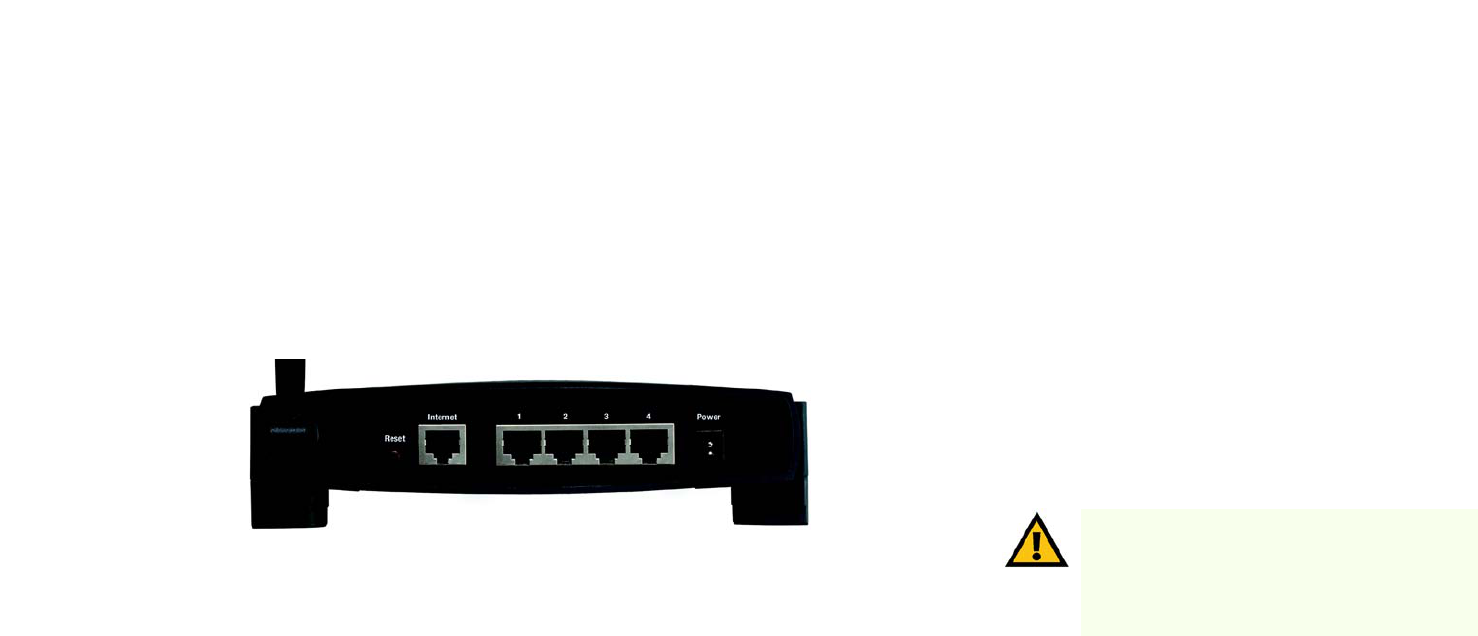
The Back Panel
The Router's ports, where the cables are connected, are located on the back panel.
Reset Button There are two ways to reset the Router's factory defaults. Either press the Reset Button, for
approximately five seconds, or restore the defaults from the Administration tab - Factory
Defaults in the Router's Web-based Utility.
Internet The Internet port is where you will connect your broadband Internet connection.
1, 2, 3, 4 These ports (1, 2, 3, 4) connect the Router to your networked PCs and other Ethernet network
devices.
Power The Power port is where you will connect the power adapter.
IMPORTANT: Resetting the Router will erase all of
your settings (Internet connection, wireless
security, and other settings) and replace them with
the factory defaults. Do not reset the Router if you
want to retain these settings.
Figure 3-1: The Router’s Back Panel

7
Chapter 3: Getting to Know the Wireless-G Broadband Router
The Front Panel
Wireless-G Broadband Router
The Front Panel
The Router’s SecureEasySetup button (the Cisco logo) and LEDs are located on the front panel.
Power Green. The Power LED lights up and will stay on while the Router is powered on. When the
Router goes through its self-diagnostic mode during every boot-up, this LED will flash. When
the diagnostic is complete, the LED will be solidly lit.
DMZ Green. The DMZ LED indicates when the DMZ function is being used. This LED will remain lit
as long as DMZ is enabled.
WLAN Green. The WLAN LED lights up whenever there is a successful wireless connection. If the LED
is flashing, the Router is actively sending or receiving data over the network.
1, 2, 3, 4 Green. These numbered LEDs, corresponding with the numbered ports on the Router’s back
panel, serve two purposes. If the LED is continuously lit, the Router is successfully connected
to a device through that port. A flashing LED indicates network activity over that port.
Internet Green. The Internet LED lights up when there is a connection made through the Internet port.
Figure 3-2: The Router’s Front Panel
8
Chapter 4: Connecting the Wireless-G Broadband Router
Overview
Wireless-G Broadband Router
Chapter 4: Connecting the Wireless-G Broadband Router
Overview
This chapter includes two sets of instructions. If the Wireless-G Broadband Router will be the only router in your
network, follow the instructions in “Hardware Installation for Connection to Your Broadband Modem.” If you want
to install the Wireless-G Broadband Router behind another router in your network, then follow the instructions in
“Hardware Installation for Connection to Another Router.”
Hardware Installation for Connection to Your Broadband Modem
1. Power down your network devices.
2. Locate an optimum location for the Router. The best place for the Router is usually at the center of your
wireless network, with line of sight to all of your mobile stations.
3. Fix the direction of the antennas. Try to place the Router in a position that will best cover your wireless
network. Normally, the higher you place the antenna, the better the performance will be.
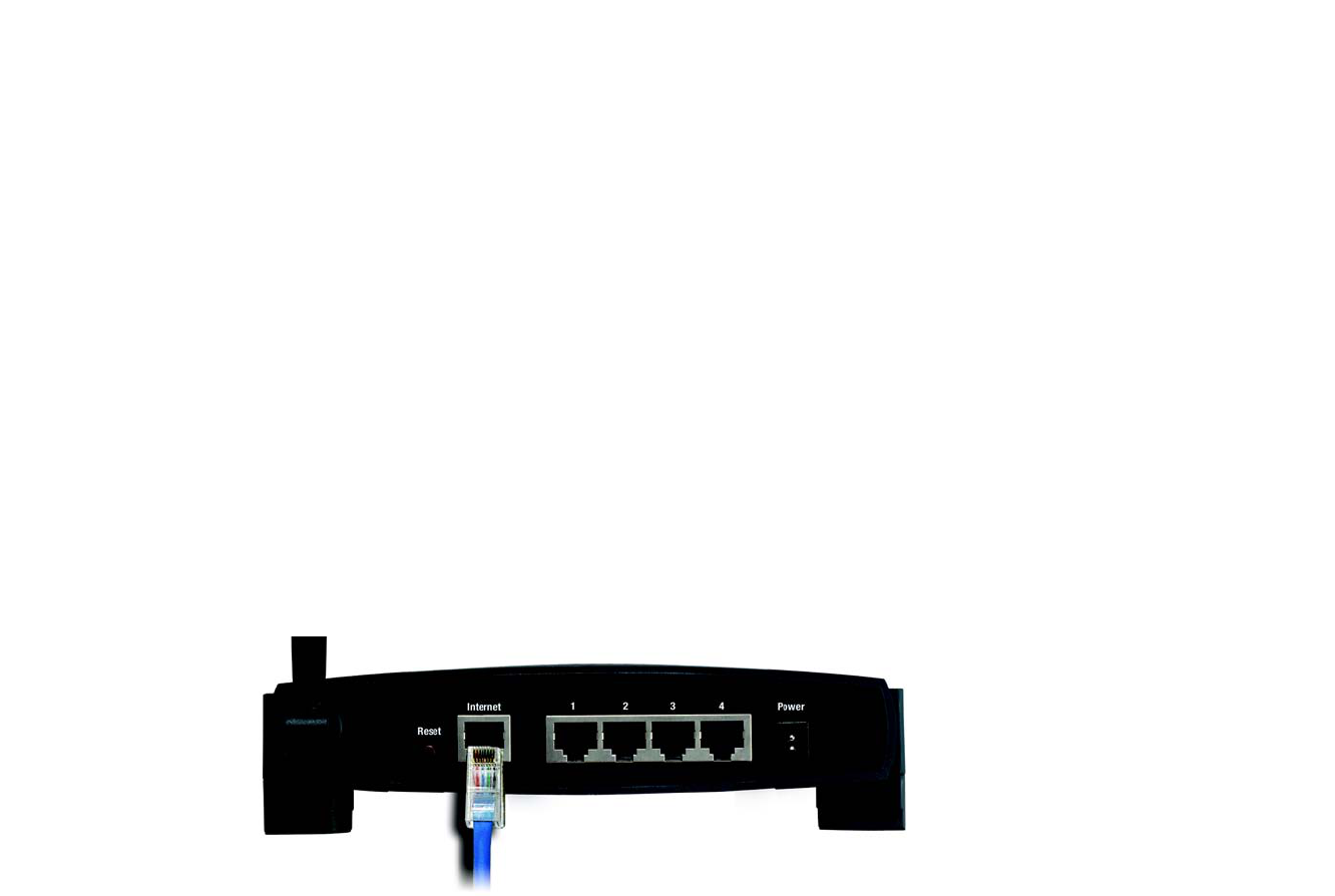
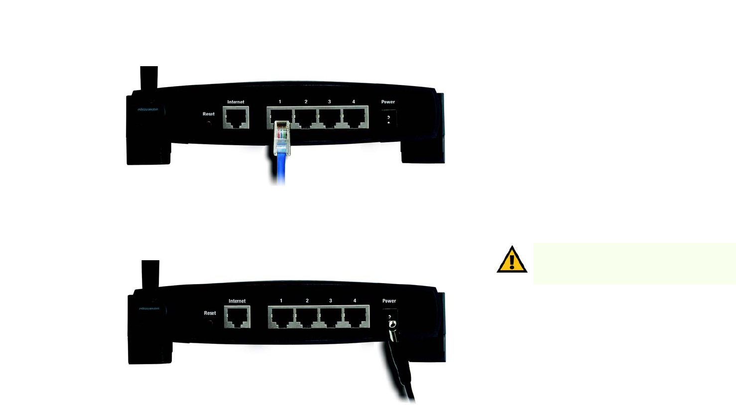
4. Connect a standard Ethernet network cable to the Router’s Internet port. Then, connect the other end of the
Ethernet cable to your cable or DSL broadband modem.
Figure 4-1: Connecting Your Internet Connection
9
Chapter 4: Connecting the Wireless-G Broadband Router
Hardware Installation for Connection to Your Broadband Modem
Wireless-G Broadband Router
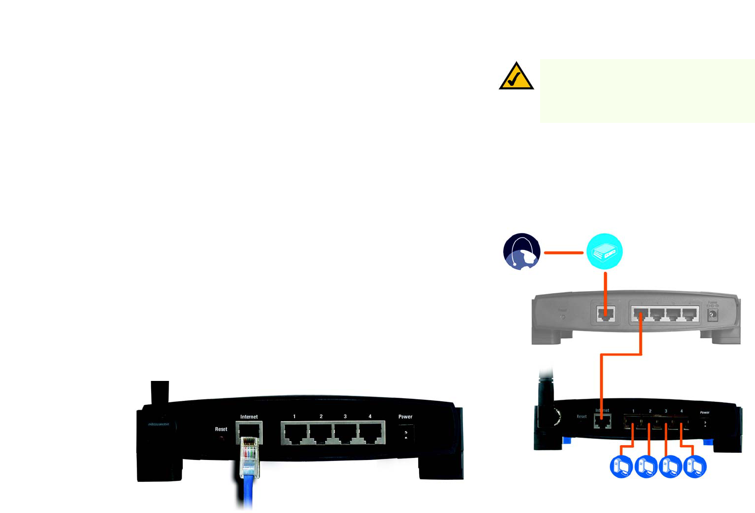
5. Connect your network PCs or Ethernet devices to the Router’s numbered ports using standard Ethernet
network cabling.
6. Connect the AC power adapter to the Router's Power port and the other end into an electrical outlet. Only use
the power adapter supplied with the Router. Use of a different adapter may result in product damage.
Now that the hardware installation is complete, proceed to “Chapter 5: Setting up the Wireless-G
Broadband Router,” for directions on how to configure the Router.
Figure 4-2: Connecting Your Network Devices
Figure 4-3: Connecting the Power
IMPORTANT: Make sure you use the power adapter
that is supplied with the Router. Use of a different
power adapter could damage the Router.
10
Chapter 4: Connecting the Wireless-G Broadband Router
Hardware Installation for Connection to Another Router
Wireless-G Broadband Router
Hardware Installation for Connection to Another Router
Before you install the Router, you must change the default IP address of the other router. This is mandatory
because both routers may be set to the same IP address by default. If you do not change the other router’s
default IP address, then you may not be able to set up the Router.
First, make sure the Router is NOT connected to your network. Then follow these instructions:
1. To access the other router’s Web-based Utility, launch Internet Explorer or Netscape Navigator, and enter the
other router’s default IP address, 192.168.1.1, in the Address field. Then press Enter.
2. A password request page will appear. Leave the User Name field blank. In the Password field, enter the
password you have set (the default password is admin). Then click the OK button.
3. The first screen that appears will display the Setup tab. In the Network Setup section, there is a setting called
Local IP Address, which is set to 192.168.1.1. Change this to 192.168.2.1.
4. Click the Save Settings button to save your change, and then exit the Web-based Utility.
5. Power down your network devices. Now you will begin the hardware installation of Router.
6. Locate an optimum location for the Router. The best place for the Router is usually at the center of your
wireless network, with line of sight to all of your mobile stations.
7. Fix the direction of the antennas. Try to place the Router in a position that will best cover your wireless
network. Normally, the higher you place the antenna, the better the performance will be.
8. Connect a standard Ethernet network cable to the Router’s Internet port. Then, connect the other end of the
Ethernet cable to one of the numbered Ethernet ports on your other router.
Figure 4-4: Diagram for Connection to Another Router
NOTE: Steps 1-4 are instructions for a typical Linksys
router; however, if you are using a non-Linksys router,
refer to the other router’s documentation for
instructions on how to change its local IP address to
192.168.2.1.
Internet Broadband
Modem
Router
Wireless-G
Broadband
Router
Figure 4-5: Connecting Another Router
Multiple PCs
11
Chapter 4: Connecting the Wireless-G Broadband Router
Hardware Installation for Connection to Another Router
Wireless-G Broadband Router
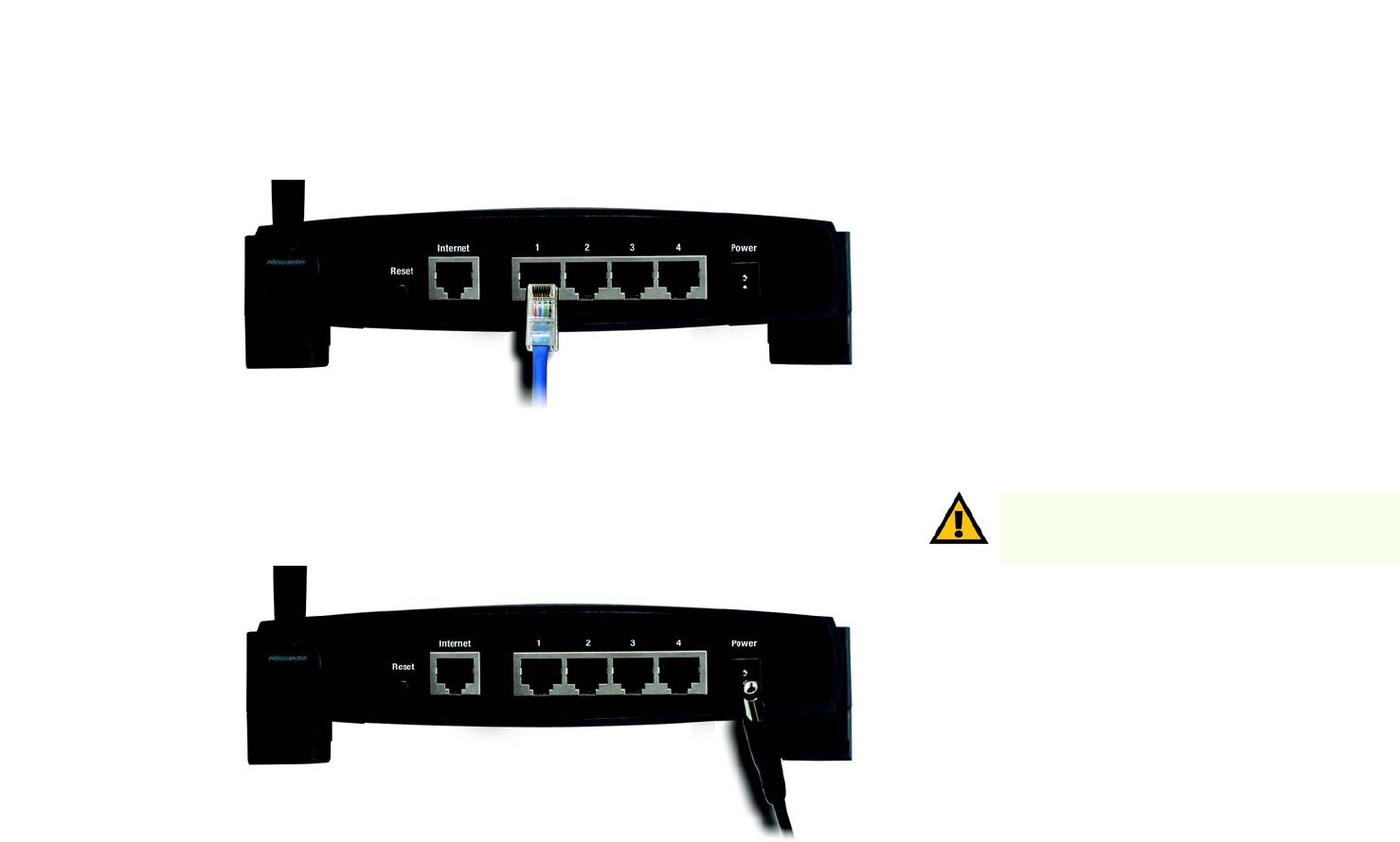
9. Decide which network computers or Ethernet devices you want to connect to the Router.
Disconnect the selected computers or devices from the other router, and then connect them to the Router’s
numbered ports using standard Ethernet network cabling.
10. Connect the AC power adapter to the Router's Power port and the other end into an electrical outlet. Only use
the power adapter supplied with the Router. Use of a different adapter may result in product damage.
Now that the hardware installation is complete, proceed to
“Chapter 5: Configuring the Wireless-G Broadband Router”.
IMPORTANT: Make sure you use the power adapter
that is supplied with the Router. Use of a different
power adapter could damage the Router.
Figure 4-6: Connecting Your Network Devices
Figure 4-7: Connecting the Power
12
Chapter 5: Configuring the Wireless-G Broadband Router
Overview
Wireless-G Broadband Router
Chapter 5: Configuring the Wireless-G Broadband
Router
Overview
Linksys recommends using the Setup CD-ROM for first-time installation of the Router. If you do not wish to run
the Setup Wizard on the Setup CD-ROM, then you can use the Web-based Utility to configure the Router. For
advanced users, you may configure the Router’s advanced settings through the Web-based Utility.
This chapter will describe each web page in the Utility and each page’s key functions. The utility can be accessed
via your web browser through use of a computer connected to the Router. For a basic network setup, most users
will use these two screens of the Utility:
• Basic Setup. On the Basic Setup screen, enter the settings provided by your ISP.
• Management. Click the Administration tab and then the Management tab. The Router’s default password is
admin. To secure the Router, change the Password from its default.
There are seven main tabs: Setup, Wireless, Security, Access Restrictions, Applications & Gaming, Administration,
and Status. Additional tabs will be available after you click one of the main tabs.
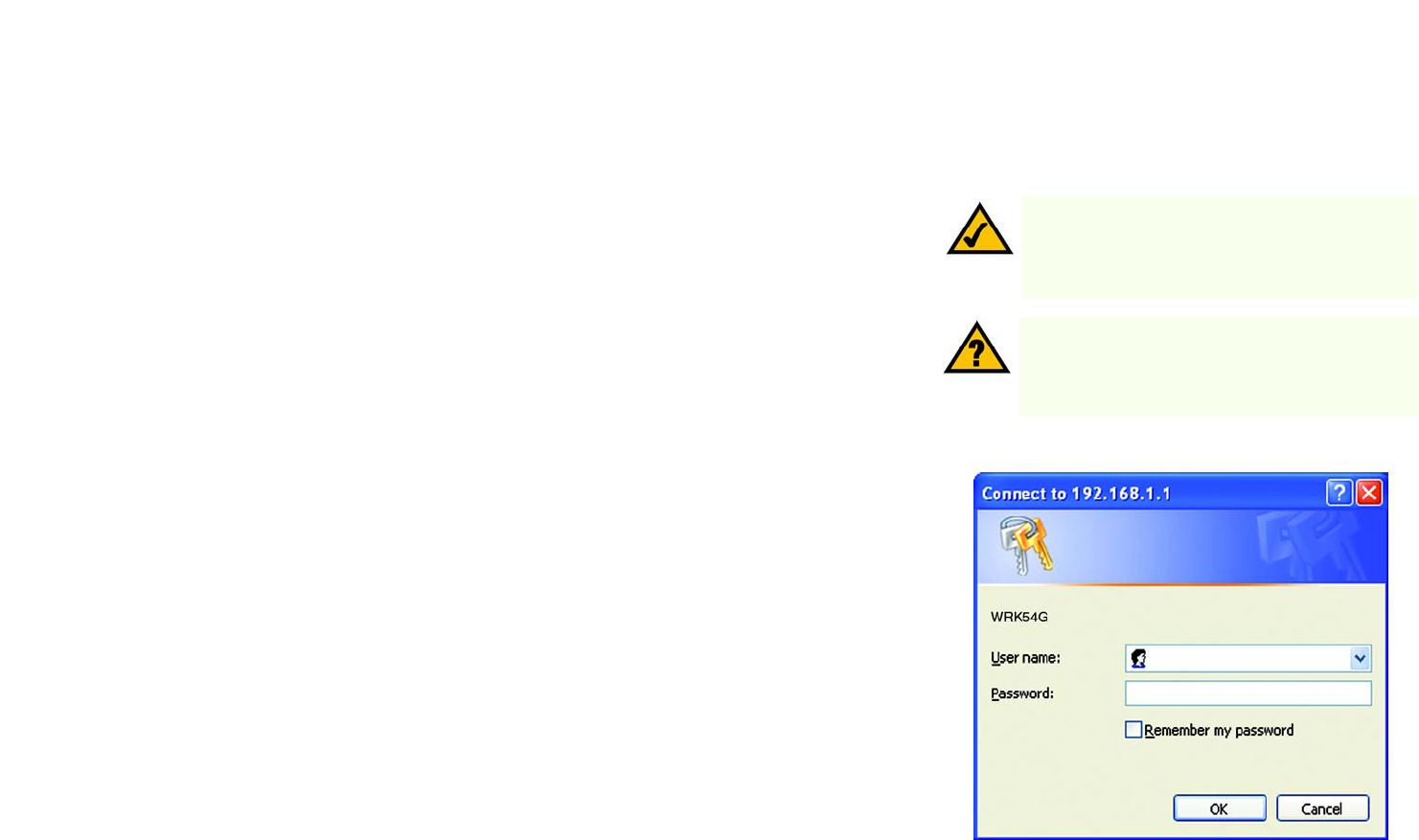
To access the Web-based Utility, launch Internet Explorer or Netscape Navigator, and enter the Router’s default IP
address, 192.168.1.1, in the Address field. Then press Enter.
A password request page will appear. (Non-Windows XP users will see a similar screen.) Leave the User Name
field blank. The first time you open the Web-based Utility, use the default password admin. (You can set a new
password from the Administration tab’s Management screen.) Then click the OK button.
HAVE YOU: Enabled TCP/IP on your PCs? PCs
communicate over the network with this protocol.
Refer to “Appendix D: Windows Help” for more
information on TCP/IP.
NOTE: For first-time installation, Linksys
recommends using the Setup Wizard on the Setup
CD-ROM. If you want to configure advanced settings,
use this chapter to learn about the Web-based Utility.
Figure 5-1: Password Screen
13
Chapter 5: Configuring the Wireless-G Broadband Router
The Setup Tab - Basic Setup
Wireless-G Broadband Router
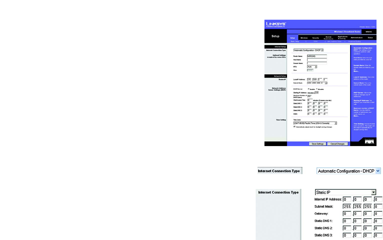
The Setup Tab - Basic Setup
The first screen that appears displays the Setup tab. This allows you to change the Router's general settings.
Change these settings as described here and click the Save Settings button to apply your changes or Cancel
Changes to cancel your changes.
Internet Setup
The Internet Setup section configures the Router to your Internet connection. Most of this information can be
obtained through your ISP.
Internet Connection Type
Choose the type of Internet connection your ISP provides from the drop-down menu.
•DHCP. By default, the Router’s Internet Connection Type is set to Automatic Configuration - DHCP, which
should be kept only if your ISP supports DHCP or you are connecting through a dynamic IP address.
•Static IP. If you are required to use a permanent IP address to connect to the Internet, select Static IP.
Internet IP Address. This is the Router’s IP address, when seen from the Internet. Your ISP will provide you
with the IP Address you need to specify here.
Subnet Mask. This is the Router’s Subnet Mask, as seen by users on the Internet (including your ISP). Your ISP
will provide you with the Subnet Mask.
Gateway. Your ISP will provide you with the Gateway Address, which is the ISP server’s IP address.
DNS. Your ISP will provide you with at least one DNS (Domain Name System) Server IP Address.
Figure 5-2: Setup Tab - Basic Setup
Figure 5-3: DHCP Connection Type
Figure 5-4: Static IP Connection Type
Static IP address: a fixed address assigned to a
computer or device connected to a network.
14
Chapter 5: Configuring the Wireless-G Broadband Router
The Setup Tab - Basic Setup
Wireless-G Broadband Router
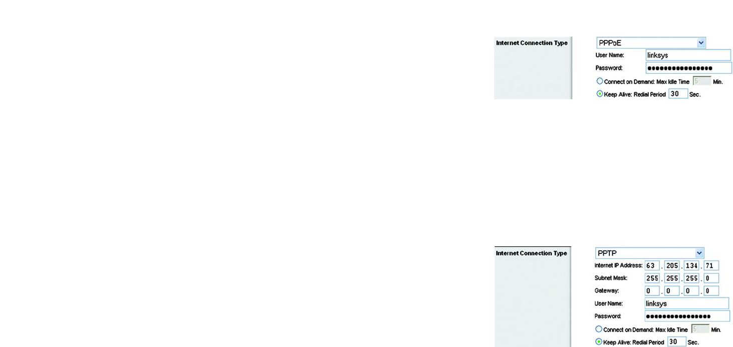
•PPPoE. Some DSL-based ISPs use PPPoE (Point-to-Point Protocol over Ethernet) to establish Internet
connections. If you are connected to the Internet through a DSL line, check with your ISP to see if they use
PPPoE. If they do, you will have to enable PPPoE.
User Name and Password. Enter the User Name and Password provided by your ISP.
Connect on Demand: Max Idle Time. You can configure the Router to cut the Internet connection after it has
been inactive for a specified period of time (Max Idle Time). If your Internet connection has been terminated
due to inactivity, Connect on Demand enables the Router to automatically re-establish your connection as
soon as you attempt to access the Internet again. If you wish to activate Connect on Demand, click the radio
button. In the Max Idle Time field, enter the number of minutes you want to have elapsed before your Internet
connection terminates.
Keep Alive Option: Redial Period. If you select this option, the Router will periodically check your Internet
connection. If you are disconnected, then the Router will automatically re-establish your connection. To use
this option, click the radio button next to Keep Alive. In the Redial Period field, you specify how often you want
the Router to check the Internet connection. The default Redial Period is 30 seconds.
•PPTP. Point-to-Point Tunneling Protocol (PPTP) is a service that applies to connections in Europe only.
Specify Internet IP Address. This is the Router’s IP address, as seen from the Internet. Your ISP will provide
you with the IP Address you need to specify here.
Subnet Mask. This is the Router’s Subnet Mask, as seen by users on the Internet (including your ISP). Your ISP
will provide you with the Subnet Mask.
Gateway. Your ISP will provide you with the Gateway Address.
User Name and Password. Enter the User Name and Password provided by your ISP.
Connect on Demand: Max Idle Time. You can configure the Router to cut the Internet connection after it has
been inactive for a specified period of time (Max Idle Time). If your Internet connection has been terminated
due to inactivity, Connect on Demand enables the Router to automatically re-establish your connection as
soon as you attempt to access the Internet again. If you wish to activate Connect on Demand, click the radio
button. In the Max Idle Time field, enter the number of minutes you want to have elapsed before your Internet
connection terminates.
Keep Alive Option: Redial Period. If you select this option, the Router will periodically check your Internet
connection. If you are disconnected, then the Router will automatically re-establish your connection. To use
this option, click the radio button next to Keep Alive. In the Redial Period field, you specify how often you want
the Router to check the Internet connection. The default Redial Period is 30 seconds.
Figure 5-5: PPPoE Connection Type
Figure 5-6: PPTP Connection Type
15
Chapter 5: Configuring the Wireless-G Broadband Router
The Setup Tab - Basic Setup
Wireless-G Broadband Router
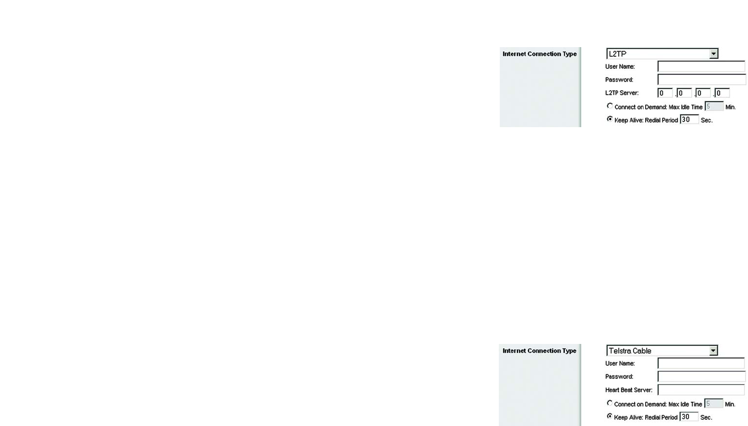
•L2TP. Layer 2 Tunneling Protocol (L2TP) is a service that applies to connections in Europe only.
User Name. Enter the User Name provided by your ISP.
Password. Enter the Password provided by your ISP.
L2TP Server. Enter the IP address of the L2TP server you are using; this should be provided by your ISP.
Connect on Demand. If you want the Router to end the Internet connection after it has been inactive for a
period of time, select Connect on Demand and designate the number of minutes you want that period of
inactivity to last.
Keep Alive. If you want the Router to periodically check your Internet connection, select Keep Alive. Then
specify how often you want the Router to check the Internet connection. If the connection is down, the Router
will automatically re-establish your connection.
•Telestra Cable. Telestra Cable is a service that applies to connections in Australia only. If your ISP is Telstra,
then select Telestra Cable.
User Name and Password. Enter the User Name and Password provided by your ISP.
Heart Beat Server. This is the IP address that the Router has, when seen from the Internet. Your ISP will
provide you with the IP Address you need to specify here.
Connect on Demand. If you want the Router to end the Internet connection after it has been inactive for a
period of time, select Connect on Demand and designate the number of minutes you want that period of
inactivity to last.
Keep Alive. If you want the Router to periodically check your Internet connection, select Keep Alive. Then
specify how often you want the Router to check the Internet connection. If the connection is down, the Router
will automatically re-establish your connection.
Figure 5-7: L2TP Connection Type
Figure 5-8: Telestra Cable Connection Type
16
Chapter 5: Configuring the Wireless-G Broadband Router
The Setup Tab - Basic Setup
Wireless-G Broadband Router
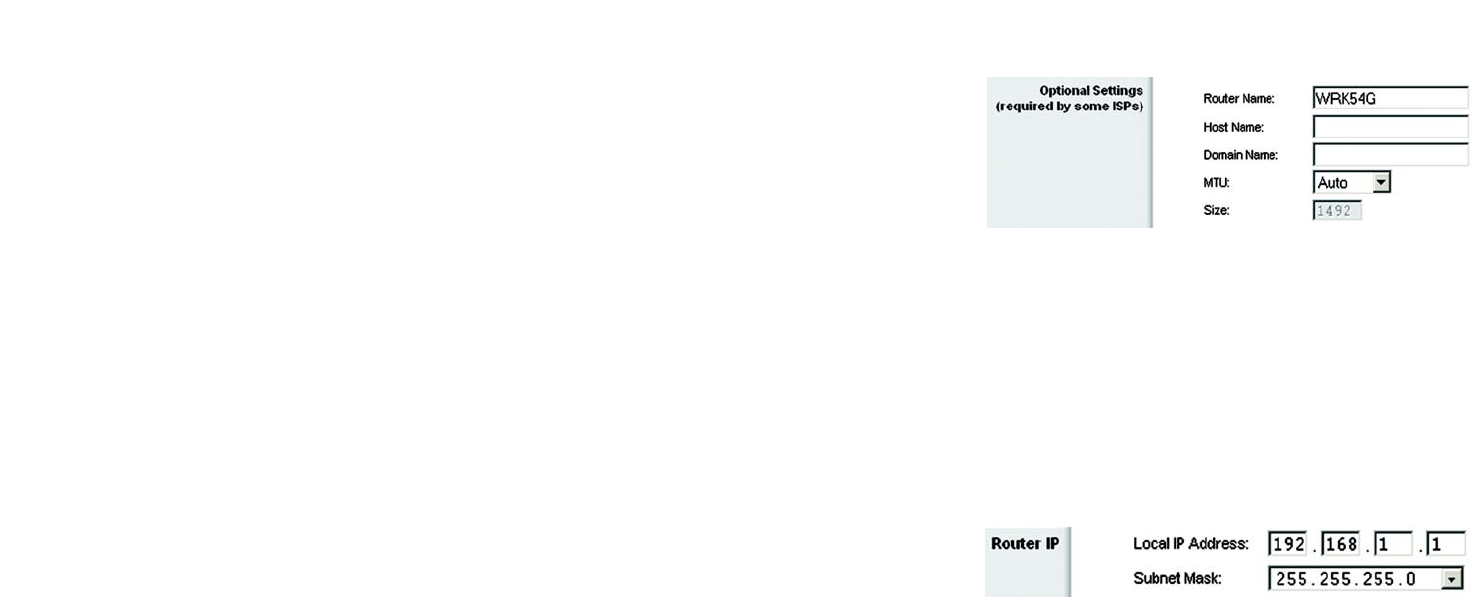
Optional Settings
Some of these settings may be required by your ISP. Verify with your ISP before making any changes.
Router Name. In this field, you can type a name of up to 39 characters to represent the Router.
Host Name/Domain Name. These fields allow you to supply a host and domain name for the Router. Some ISPs,
usually cable ISPs, require these names as identification. You may have to check with your ISP to see if your
broadband Internet service has been configured with a host and domain name. In most cases, leaving these
fields blank will work.
MTU. MTU is the Maximum Transmission Unit. It specifies the largest packet size permitted for Internet
transmission. The default setting, Manual, allows you to enter the largest packet size that will be transmitted.
The recommended size, entered in the Size field, is 1492. You should leave this value in the 1200 to 1500 range.
To have the Router select the best MTU for your Internet connection, select Auto.
Network Setup
The Network Setup section changes the settings on the network connected to the Router’s Ethernet ports.
Wireless Setup is performed through the Wireless tab.
Router IP
This presents both the Router’s IP Address and Subnet Mask as seen by your network.
Figure 5-9: Optional Settings
Figure 5-10: Router IP
17
Chapter 5: Configuring the Wireless-G Broadband Router
The Setup Tab - Basic Setup
Wireless-G Broadband Router
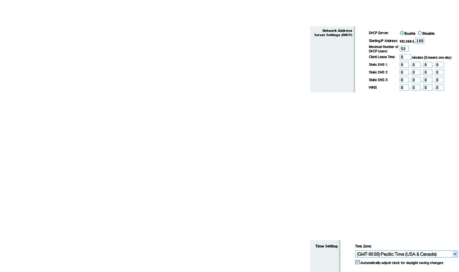
Network Address Server Settings (DHCP)
The settings allow you to configure the Router’s Dynamic Host Configuration Protocol (DHCP) server function. The
Router can be used as a DHCP server for your network. A DHCP server automatically assigns an IP address to
each computer on your network. If you choose to enable the Router’s DHCP server option, you must configure all
of your network PCs to connect to a DHCP server (the Router), and make sure there is no other DHCP server on
your network.
DHCP Server. DHCP is enabled by factory default. If you already have a DHCP server on your network, or you
don’t want a DHCP server, then click the Disable radio button (no other DHCP features will be available).
Starting IP Address. Enter a value for the DHCP server to start with when issuing IP addresses. Because the
Router’s default IP address is 192.168.1.1, the Starting IP Address must be 192.168.1.2 or greater, but smaller
than 192.168.1.253. The default Starting IP Address is 192.168.1.100.
Maximum Number of DHCP Users. Enter the maximum number of PCs that you want the DHCP server to assign
IP addresses to. This number cannot be greater than 253. The default is 50.
Client Lease Time. The Client Lease Time is the amount of time a network user will be allowed connection to the
Router with their current dynamic IP address. Enter the amount of time, in minutes, that the user will be “leased”
this dynamic IP address. After the time is up, the user will be automatically assigned a new dynamic IP address.
The default is 0 minutes, which means one day.
Static DNS (1-3). The Domain Name System (DNS) is how the Internet translates domain or website names into
Internet addresses or URLs. Your ISP will provide you with at least one DNS Server IP Address. If you wish to use
another, type that IP Address in one of these fields. You can type up to three DNS Server IP Addresses here. The
Router will use these for quicker access to functioning DNS servers.
WINS. The Windows Internet Naming Service (WINS) manages each PC’s interaction with the Internet. If you use
a WINS server, enter that server’s IP Address here. Otherwise, leave this blank.
Time Setting
Change the time zone in which your network functions from this pull-down menu. (You can even automatically
adjust for daylight savings time.)
Figure 5-11: Network Address Server Settings
Figure 5-12: Time Setting
18
Chapter 5: Configuring the Wireless-G Broadband Router
The Setup Tab - DDNS
Wireless-G Broadband Router
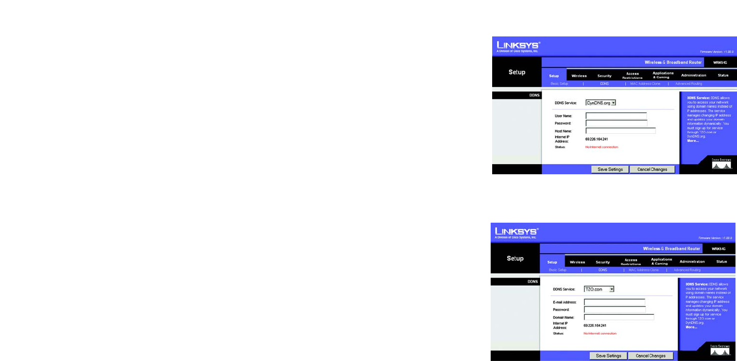
The Setup Tab - DDNS
The Router offers a Dynamic Domain Name System (DDNS) feature. DDNS lets you assign a fixed host and domain
name to a dynamic Internet IP address. It is useful when you are hosting your own website, FTP server, or other
server behind the Router. Before you can use this feature, you need to sign up for DDNS service with a DDNS
service provider, www.dyndns.org or www.TZO.com.
Select your DDNS service, DynDNS or TZO, from the DDNS Service pull-down menu. You may be asked for a User
Name, Password, E-mail Address, Domain Name, or Host Name. Simply enter the appropriate information for your
DDNS account.
The following information will also be displayed.
Internet IP Address. This is the Router’s current IP Address as seen on the Internet.
Status. This displays the status of the DDNS connection.
Change these settings as described here and click the Save Settings button to apply your changes or Cancel
Changes to cancel your changes.
Figure 5-13: Setup Tab - DDNS - DynDNS account
Figure 5-14: Setup Tab - DDNS - TZO account
19
Chapter 5: Configuring the Wireless-G Broadband Router
The Setup Tab - MAC Address Clone
Wireless-G Broadband Router
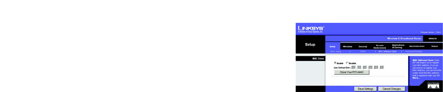
The Setup Tab - MAC Address Clone
A MAC address is a 12-digit code assigned to a unique piece of hardware for identification. Some ISPs will
require you to register a MAC address in order to access the Internet. If you do not wish to re-register the MAC
address with your ISP, you may assign the MAC address you have currently registered with your ISP to the Router
with the MAC Address Clone feature.
Enable/Disable. To have the MAC Address cloned, click the radio button beside Enable.
User Defined Entry. Enter the MAC Address registered with your ISP here.
Clone Your PC’s MAC Address. Clicking this button will clone the MAC address.
Change these settings as described here and click the Save Settings button to apply your changes or Cancel
Changes to cancel your changes.
Figure 5-15: Setup Tab - MAC Address Clone
20
Chapter 5: Configuring the Wireless-G Broadband Router
The Setup Tab - Advanced Routing
Wireless-G Broadband Router
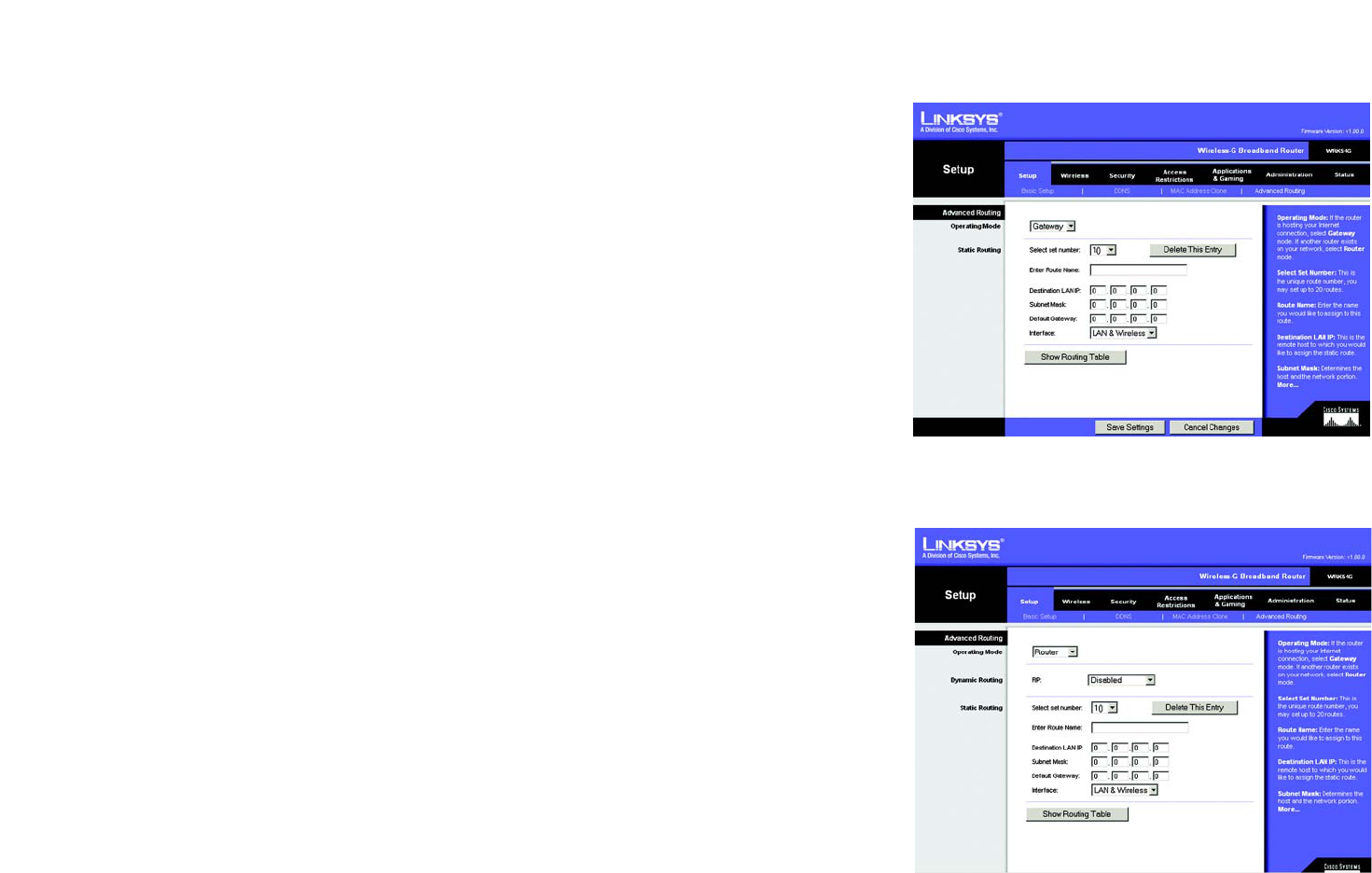
The Setup Tab - Advanced Routing
This tab is used to set up the Router’s advanced functions. Operating Mode allows you to select the type(s) of
advanced functions you use. Dynamic Routing will automatically adjust how packets travel on your network. Static
Routing sets up a fixed route to another network destination.
Operating Mode
. Select the mode in which this Router will function. If this Router is hosting your network’s
connection to the Internet, select
Gateway
. If another Router exists on your network, select
Router
. When Router is
chosen,
Dynamic Routing
will be enabled.
Dynamic Routing
. This feature enables the Router to automatically adjust to physical changes in the network’s
layout and exchange routing tables with the other router(s). The Router determines the network packets’ route
based on the fewest number of hops between the source and the destination. This feature is
Disabled
by default.
From the drop-down menu, you can also select
LAN & Wireless
, which performs dynamic routing over your
Ethernet and wireless networks. You can also select
WAN
, which performs dynamic routing with data coming from
the Internet. Finally, selecting
Both
enables dynamic routing for both networks, as well as data from the Internet.
Static Routing
. To set up a static route between the Router and another network, select a number from the Static
Routing drop-down list. (A static route is a pre-determined pathway that network information must travel to reach a
specific host or network.) Enter the information described below to set up a new static route. (Click the
Delete This
Entry
button to delete a static route.)
Enter Route Name
. Enter a name for the Route here, using a maximum of 25 alphanumeric characters.
Destination LAN IP
. The Destination LAN IP is the address of the remote network or host to which you want to
assign a static route.
Subnet Mask
. The Subnet Mask determines which portion of a Destination LAN IP address is the network
portion, and which portion is the host portion.
Default Gateway
. This is the IP address of the gateway device that allows for contact between the Router and
the remote network or host.
Interface
. This interface tells you whether the Destination IP Address is on the
LAN & Wireless
(Ethernet and
wireless networks), the
WAN
(Internet), or
Loopback
(a dummy network in which one PC acts like a network—
necessary for certain software programs).
Click the
Show Routing Table
button to view the Static Routes you’ve already set up.
Change these settings as described here and click the
Save Settings
button to apply your changes or
Cancel
Changes
to cancel your changes.
Figure 5-17: Setup Tab - Advanced Routing (Router)
Figure 5-16: Setup Tab - Advanced Routing (Gateway)
21
Chapter 5: Configuring the Wireless-G Broadband Router
The Wireless Tab - Basic Wireless Settings
Wireless-G Broadband Router
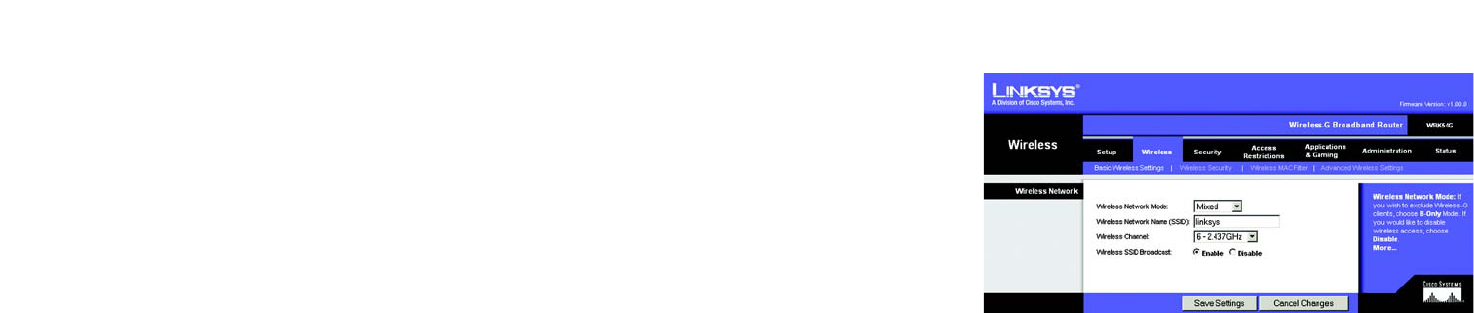
The Wireless Tab - Basic Wireless Settings
The basic settings for wireless networking are set on this screen.
Wireless Network Mode. From this drop-down menu, you can select the wireless standards running on your
network. If you have both 802.11g and 802.11b devices in your network, keep the default setting, Mixed. If you
have only 802.11g devices, select G-Only. If you have only 802.11b devices, select B-Only. If you do not have any
802.11g and 802.11b devices in your network, select Disable.
Wireless Network Name (SSID). The SSID is the network name shared among all devices in a wireless network.
The SSID must be identical for all devices in the wireless network. It is case-sensitive and must not exceed 32
characters (use any of the characters on the keyboard). Make sure this setting is the same for all devices in your
wireless network. For added security, you should change the default SSID (linksys) to a unique name.
Wireless Channel. Select the appropriate channel from the list provided to correspond with your network
settings. All devices in your wireless network must be broadcast on the same channel in order to function
correctly.
Wireless SSID Broadcast. When wireless clients survey the local area for wireless networks to associate with,
they will detect the SSID broadcast by the Router. To broadcast the Router's SSID, keep the default setting,
Enable. If you do not want to broadcast the Router's SSID, then select Disable.
Change these settings as described here and click the Save Settings button to apply your changes or Cancel
Changes to cancel your changes.
Figure 5-18: Wireless Tab - Basic Wireless Settings
22
Chapter 5: Configuring the Wireless-G Broadband Router
The Wireless Tab - Wireless Security
Wireless-G Broadband Router
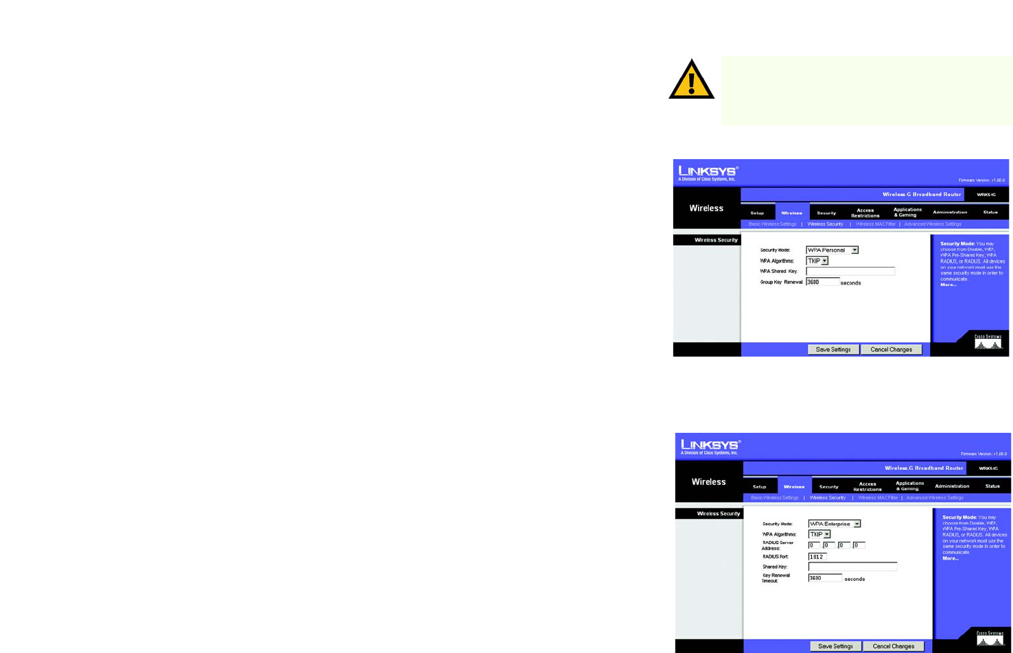
The Wireless Tab - Wireless Security
The Wireless Security settings configure the security of your wireless network. There are four wireless security
mode options supported by the Router: WPA Personal, WPA Enterprise, WPA2 Personal, WPA2 Enterprise,
RADIUS, and WEP. (WEP stands for Wired Equivalent Privacy, WPA stands for Wi-Fi Protected Access, which is a
security standard stronger than WEP encryption. WPA2 is stronger than WPA. WPA Enterprise is WPA used in
coordination with a RADIUS server. RADIUS stands for Remote Authentication Dial-In User Service.) These are
briefly discussed here. For detailed instructions on configuring wireless security for the Router, turn to “Appendix
B: Wireless Security.”
WPA Personal. WPA gives you two encryption methods, TKIP and AES, with dynamic encryption keys. Select the
type of algorithm, TKIP or AES. Enter a WPA Shared Key of 8-63 characters. Then enter a Group Key Renewal
period, which instructs the Router how often it should change the encryption keys.
WPA Enterprise. This option features WPA used in coordination with a RADIUS server. (This should only be used
when a RADIUS server is connected to the Router.) First, select the type of WPA algorithm you want to use, TKIP
or AES. Enter the RADIUS server’s IP Address and port number, along with a key shared between the Router and
the server. Last, enter a Key Renewal Timeout, which instructs the Router how often it should change the
encryption keys.
Figure 5-20: Wireless Tab - Wireless Security
(WPA Enterprise)
Figure 5-19: Wireless Tab - Wireless Security
(WPA Personal)
IMPORTANT: If you are using WPA, always remember
that each device in your wireless network MUST use
the same WPA method and shared key, or else the
network will not function properly.
23
Chapter 5: Configuring the Wireless-G Broadband Router
The Wireless Tab - Wireless Security
Wireless-G Broadband Router
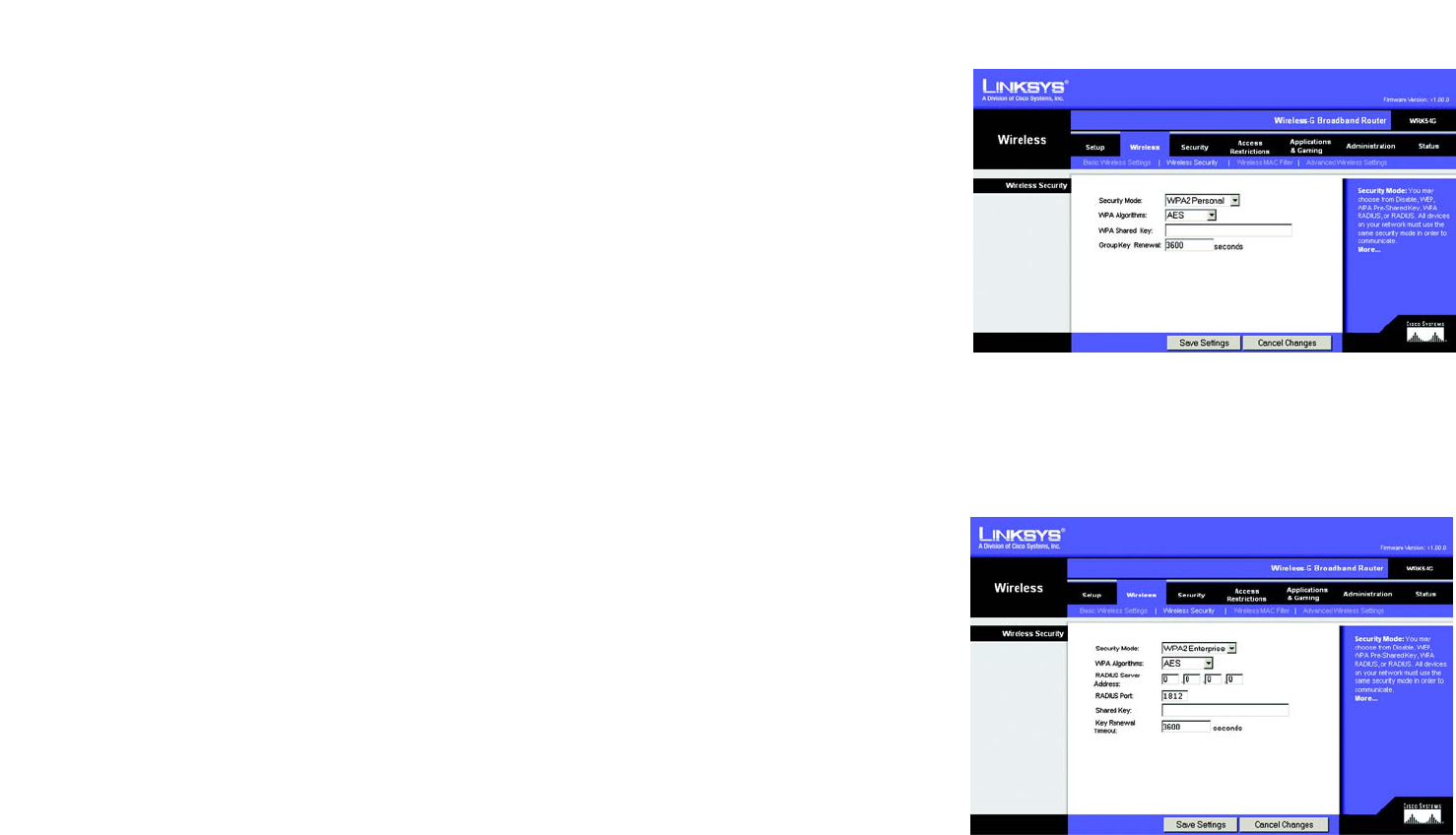
WPA2 Personal. WPA2 gives you two encryption methods, TKIP and AES, with dynamic encryption keys. Select
the type of algorithm, AES, or TKIP + AES. Enter a WPA Shared Key of 8-63 characters. Then enter a Group Key
Renewal period, which instructs the Router how often it should change the encryption keys.
WPA2 Enterprise. This option features WPA2 used in coordination with a RADIUS server. (This should only be
used when a RADIUS server is connected to the Router.) First, select the type of WPA algorithm you want to use,
AES, or TKIP + AES. Enter the RADIUS server’s IP Address and port number, along with a key shared between the
Router and the server. Last, enter a Key Renewal Timeout, which instructs the Router how often it should change
the encryption keys.
Figure 5-21: Wireless Tab - Wireless Security
(WPA2 Personal)
Figure 5-22: Wireless Tab - Wireless Security
(WPA2 Enterprise)
24
Chapter 5: Configuring the Wireless-G Broadband Router
The Wireless Tab - Wireless Security
Wireless-G Broadband Router
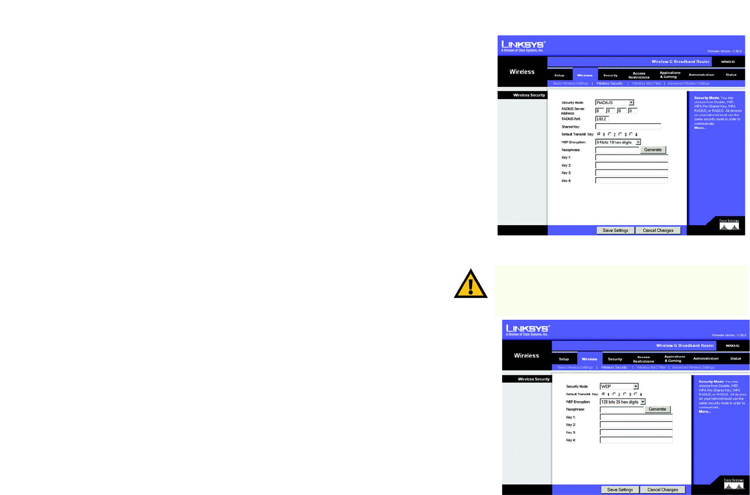
RADIUS. This option features WEP used in coordination with a RADIUS server. (This should only be used when a
RADIUS server is connected to the Router.) First, enter the RADIUS server’s IP Address and port number, along
with a key shared between the Router and the server. Then, select a Default Transmit Key (choose which Key to
use), and a level of WEP encryption, 64 bits 10 hex digits or 128 bits 26 hex digits. Last, either generate a
WEP key using the Passphrase or enter the WEP key manually.
WEP. WEP is a basic encryption method, which is not as secure as WPA. To use WEP, select a Default Transmit Key
(choose which Key to use), and a level of WEP encryption, 64 bits 10 hex digits or 128 bits 26 hex digits. Then
either generate a WEP key using the Passphrase or enter the WEP key manually.
Change these settings as described here and click the Save Settings button to apply your changes or Cancel
Changes to cancel your changes. For detailed instructions on configuring wireless security for the Router, turn to
“Appendix B: Wireless Security.”
Figure 5-23: Wireless Tab - Wireless Security (RADIUS)
IMPORTANT: If you are using WEP encryption, always remember
that each device in your wireless network MUST use the same
WEP encryption method and encryption key, or else your wireless
network will not function properly.
Figure 5-24: Wireless Tab - Wireless Security (WEP)
25
Chapter 5: Configuring the Wireless-G Broadband Router
The Wireless Tab - Wireless MAC Filter
Wireless-G Broadband Router
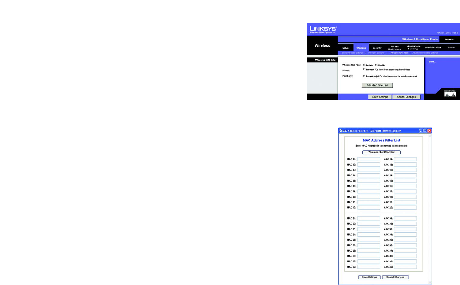
The Wireless Tab - Wireless MAC Filter
Wireless access can be filtered by using the MAC addresses of the wireless devices transmitting within your
network’s radius.
Wireless MAC Filter. To filter wireless users by MAC Address, either permitting or blocking access, click Enable.
If you do not wish to filter users by MAC Address, select Disable.
Prevent. Clicking this button will block wireless access by MAC Address.
Permit Only. Clicking this button will allow wireless access by MAC Address.
Edit MAC Address Filter List. Clicking this button will open the MAC Address Filter List. On this screen, you can
list users, by MAC Address, to whom you wish to provide or block access. For easy reference, click the Wireless
Client MAC List button to display a list of network users by MAC Address.
Change these settings as described here and click the Save Settings button to apply your changes or Cancel
Changes to cancel your changes.
Figure 5-25: Wireless Tab - Wireless MAC Filter
Figure 5-26: MAC Address Filter List
26
Chapter 5: Configuring the Wireless-G Broadband Router
The Wireless Tab - Advanced Wireless Settings
Wireless-G Broadband Router
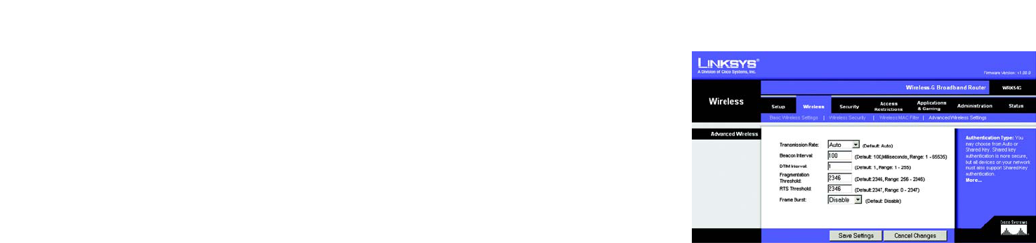
The Wireless Tab - Advanced Wireless Settings
This tab is used to set up the Router’s advanced wireless functions. These settings should only be adjusted by an
expert administrator as incorrect settings can reduce wireless performance.
Transmission Rate. The rate of data transmission should be set depending on the speed of your wireless
network. You can select from a range of transmission speeds, or you can select Auto to have the Router
automatically use the fastest possible data rate and enable the Auto-Fallback feature. Auto-Fallback will
negotiate the best possible connection speed between the Router and a wireless client. The default value is Auto.
Beacon Interval. The default value is 100. Enter a value between 20 and 1,000 milliseconds. The Beacon
Interval value indicates the frequency interval of the beacon. A beacon is a packet broadcast by the Router to
synchronize the wireless network.
DTIM Interval. This value, between 1 and 255, indicates the interval of the Delivery Traffic Indication Message
(DTIM). A DTIM field is a countdown field informing clients of the next window for listening to broadcast and
multicast messages. When the Router has buffered broadcast or multicast messages for associated clients, it
sends the next DTIM with a DTIM Interval value. Its clients hear the beacons and awaken to receive the broadcast
and multicast messages. The default value is 1.
Fragmentation Threshold. This value specifies the maximum size for a packet before data is fragmented into
multiple packets. If you experience a high packet error rate, you may slightly increase the Fragmentation
Threshold. Setting the Fragmentation Threshold too low may result in poor network performance. Only minor
reduction of the default value is recommended. In most cases, it should remain at its default value of 2346.
RTS Threshold. Should you encounter inconsistent data flow, only minor reduction of the default value, 2347, is
recommended. If a network packet is smaller than the preset RTS threshold size, the RTS/CTS mechanism will
not be enabled. The Router sends Request to Send (RTS) frames to a particular receiving station and negotiates
the sending of a data frame. After receiving an RTS, the wireless station responds with a Clear to Send (CTS)
frame to acknowledge the right to begin transmission. The RTS Threshold value should remain at its default value
of 2347.
Frame Burst. Enabling this option should provide your network with greater performance, depending on the
manufacturer of your wireless products. If you are not sure how to use this option, keep the default, Disable.
Change these settings as described here and click the Save Settings button to apply your changes or Cancel
Changes to cancel your changes.
Figure 5-27: Wireless Tab - Advanced Wireless Settings
27
Chapter 5: Configuring the Wireless-G Broadband Router
The Security Tab - Firewall
Wireless-G Broadband Router
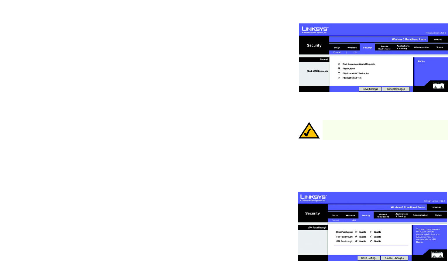
The Security Tab - Firewall
Block WAN Requests. Enable the Block WAN Request feature by checking the box beside Block Anonymous
Internet Requests and you can prevent your network from being “pinged,” or detected, by other Internet users.
The Block WAN Request feature also reinforces your network security by hiding your network ports. Both
functions of the Block WAN Request feature make it more difficult for outside users to work their way into your
network. This feature is enabled by default. Select Disabled to allow anonymous Internet requests.
Filter Multicast. Multicasting allows for multiple transmissions to specific recipients at the same time. If
multicasting is permitted, then the Router will allow IP multicast packets to be forwarded to the appropriate
computers. Select Enabled to filter multicasting, or Disabled to disable this feature.
Filter Internet NAT Redirection. This feature uses port forwarding to block access to local servers from local
networked computers. Select Enabled to filter Internet NAT redirection, or Disabled to disable this feature.
Filter IDENT (Port 113). This feature keeps port 113 from being scanned by devices outside of your local
network. Select Enabled to filter port 113, or Disabled to disable this feature.
Change these settings as described here and click the Save Settings button to apply your changes or Cancel
Changes to cancel your changes.
The Security Tab - VPN Passthrough
Use the settings on this tab to allow VPN tunnels using IPSec, PPTP, or L2TP protocols to pass through the
Router’s firewall.
IPSec Pass-through. Internet Protocol Security (IPSec), enabled by default, is a suite of protocols used to
implement secure exchange of packets at the IP layer. To turn off this feature, click Disable.
PPTP Pass-through. Point-to-Point Tunneling Protocol (PPTP), enabled by default, allows the Point-to-Point
Protocol (PPP) to be tunneled through an IP network. To turn off this feature, click Disable.
L2TP Pass-through. Layer 2 Tunneling Protocol is the method used to enable Point-to-Point sessions via the
Internet on the Layer 2 level. To allow L2TP tunnels to pass through the Router, click Enable. L2TP Pass-Through
is enabled by default.
Change these settings as described here and click the Save Settings button to apply your changes or Cancel
Changes to cancel your changes.
Figure 5-28: Security Tab - Firewall
Figure 5-29: Security Tab - VPN Passthrough
NOTE: The Wireless-G Broadband Router always has
its firewall protection enabled.
28
Chapter 5: Configuring the Wireless-G Broadband Router
The Access Restrictions Tab - Internet Access
Wireless-G Broadband Router
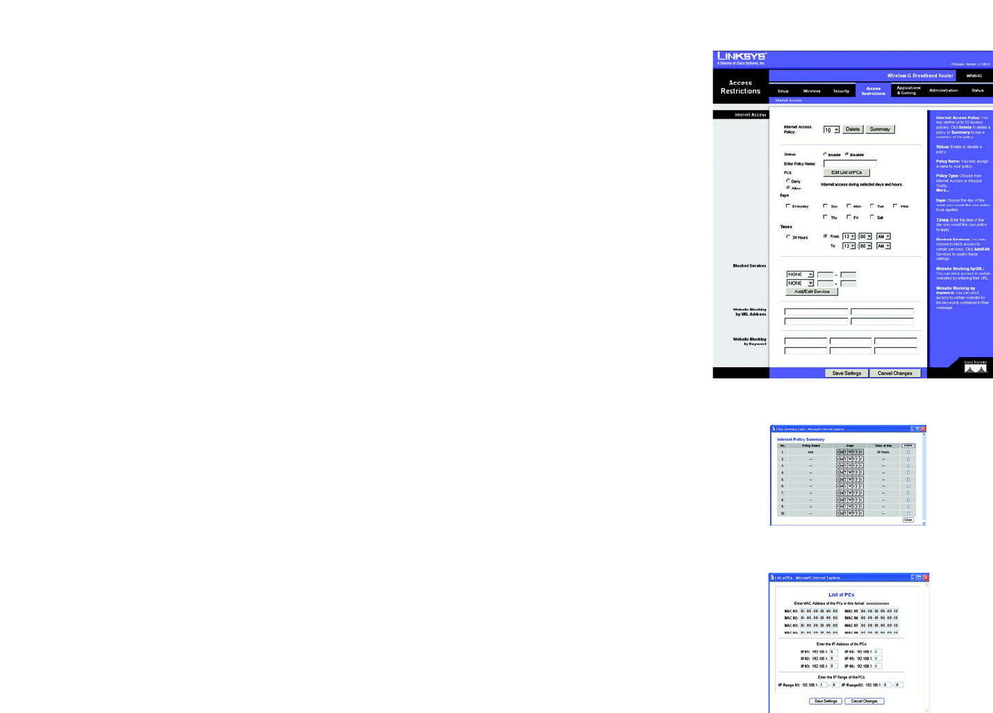
Figure 5-30: Access Restrictions Tab - Internet Access
Figure 5-31: Internet Policy Summary
Figure 5-32: List of PCs
The Access Restrictions Tab - Internet Access
The Internet Access screen allows you to block or allow specific kinds of Internet usage and traffic, such as
Internet access, designated services, websites, and inbound traffic during specific days and times.
Internet Access Policy. Access can be managed by a policy. Use the settings on this screen to establish an
access policy (after the Save Settings button is clicked). Selecting a policy from the drop-down menu will
display that policy’s settings. To delete a policy, select that policy’s number and click the Delete button. To view
all the policies, click the Summary button. (Policies can be deleted from the Summary screen by selecting the
policy or policies and clicking the Delete button. To return to the Internet Access tab, click the Close button.)
Status. Policies are disabled by default. To enable a policy, select the policy number from the drop-down menu,
and click the radio button beside Enable.
You can create two kinds of policies, one kind to manage Internet access and another kind to manage inbound
traffic.
To create an Internet Access policy:
1. Select a number from the Internet Access Policy drop-down menu.
2. To enable this policy, click the radio button beside Enable.
3. Enter a Policy Name in the field provided.
4. Select Internet Access as the Policy Type.
5. Click the Edit List button to select which PCs will be affected by the policy. The List of PCs screen will appear.
You can select a PC by MAC Address or IP Address. You can also enter a range of IP Addresses if you want this
policy to affect a group of PCs. After making your changes, click the Save Settings button to apply your
changes or Cancel Changes to cancel your changes. Then click the Close button.
6. Click the appropriate option, Deny or Allow, depending on whether you want to block or allow Internet access
for the PCs you listed on the List of PCs screen.
7. Decide which days and what times you want this policy to be enforced. Select the individual days during
which the policy will be in effect, or select Everyday. Then enter a range of hours and minutes during which
the policy will be in effect, or select 24 Hours.
8. You can filter access to various services accessed over the Internet, such as FTP or telnet, by selecting
services from the drop-down menus next to Blocked Services. (You can block up to 20 services.)
29
Chapter 5: Configuring the Wireless-G Broadband Router
The Access Restrictions Tab - Internet Access
Wireless-G Broadband Router
Then, enter the range of ports you want to filter.
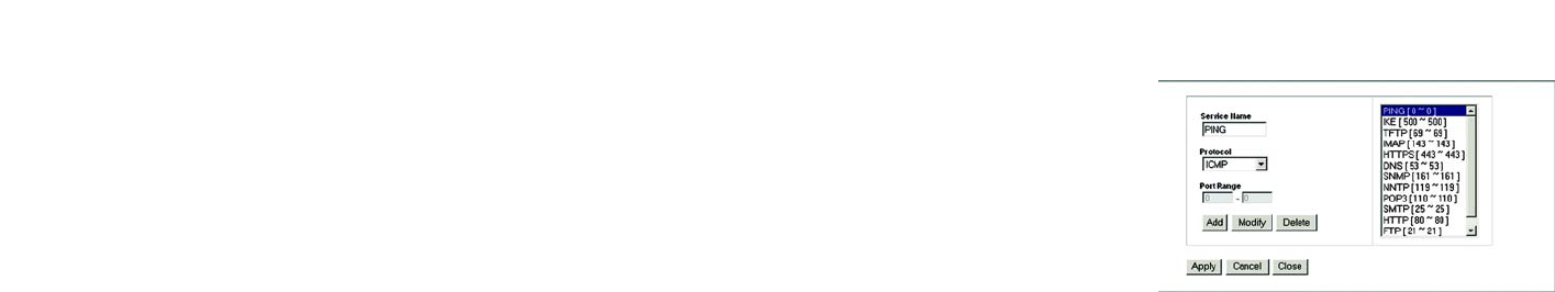
If the service you want to block is not listed or you want to edit a service’s settings, then click the Add/Edit
Service button. Then the Port Services screen will appear.
To add a service, enter the service’s name in the Service Name field. Select its protocol from the Protocol
drop-down menu, and enter its range in the Port Range fields. Then click the Add button.
To modify a service, select it from the list on the right. Change its name, protocol setting, or port range. Then
click the Modify button.
To delete a service, select it from the list on the right. Then click the Delete button.
When you are finished making changes on the Port Services screen, click the Apply button to save changes.
If you want to cancel your changes, click the Cancel button. To close the Port Services screen and return to
the Access Restrictions screen, click the Close button.
9. If you want to block websites with specific URL addresses, enter each URL in a separate field next to Website
Blocking by URL Address.
10. If you want to block websites using specific keywords, enter each keyword in a separate field next to Website
Blocking by Keyword.
Change these settings as described here and click the Save Settings button to apply your changes or Cancel
Changes to cancel your changes.
Figure 5-33: Port Services
30
Chapter 5: Configuring the Wireless-G Broadband Router
The Applications and Gaming Tab - Port Range Forward
Wireless-G Broadband Router
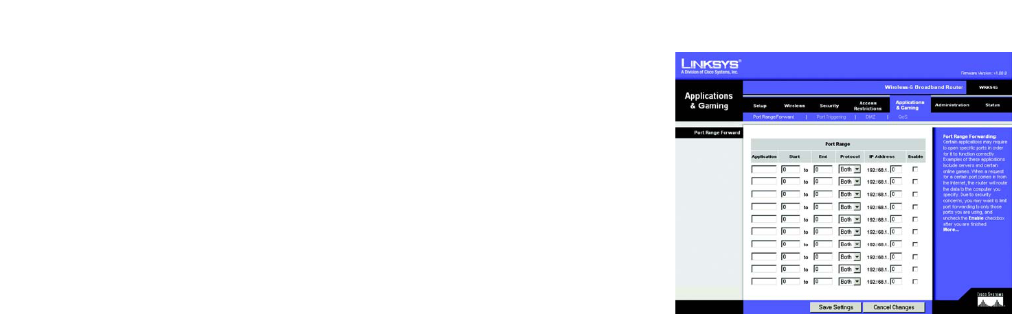
The Applications and Gaming Tab - Port Range Forward
The Applications and Gaming Tab allows you to set up public services on your network, such as web servers, ftp
servers, e-mail servers, or other specialized Internet applications. (Specialized Internet applications are any
applications that use Internet access to perform functions such as videoconferencing or online gaming. Some
Internet applications may not require any forwarding.)
To forward a port, enter the information on each line for the criteria required. The criteria are described here.
Application. In this field, enter the name you wish to give the application. Each name can be up to 12 characters.
Start/End. This is the port range. Enter the number that starts the port range under Start and the number that
ends the range under End.
Protocol. Enter the protocol used for this application, either TCP or UDP, or Both.
IP Address. For each application, enter the IP Address of the PC running the specific application.
Enable. Click the Enable checkbox to enable port forwarding for the relevant application.
Change these settings as described here and click the Save Settings button to apply your changes or Cancel
Changes to cancel your changes.
Figure 5-34: Applications and Gaming Tab - Port
Range Forward
31
Chapter 5: Configuring the Wireless-G Broadband Router
The Applications & Gaming Tab - Port Triggering
Wireless-G Broadband Router
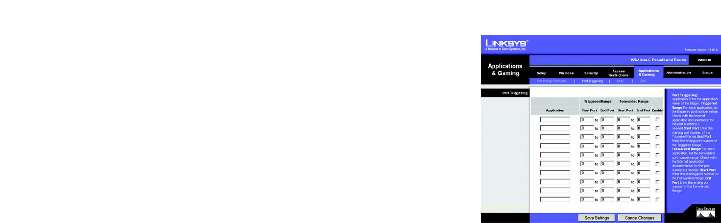
The Applications & Gaming Tab - Port Triggering
The Port Triggering screen allows the Router to watch outgoing data for specific port numbers. The IP address of
the computer that sends the matching data is remembered by the Router, so that when the requested data
returns through the Router, the data is pulled back to the proper computer by way of IP address and port
mapping rules.
Port Triggering
Application. Enter the application name of the trigger.
Triggered Range
For each application, list the triggered port number range. Check with the Internet application documentation for
the port number(s) needed.
Start Port. Enter the starting port number of the Triggered Range.
End Port. Enter the ending port number of the Triggered Range.
Forwarded Range
For each application, list the forwarded port number range. Check with the Internet application documentation for
the port number(s) needed.
Start Port. Enter the starting port number of the Forwarded Range.
End Port. Enter the ending port number of the Forwarded Range.
Change these settings as described here and click the Save Settings button to apply your changes or Cancel
Changes to cancel your changes.
Figure 5-35: Applications and Gaming Tab -
Port Triggering
32
Chapter 5: Configuring the Wireless-G Broadband Router
The Applications and Gaming Tab - DMZ
Wireless-G Broadband Router
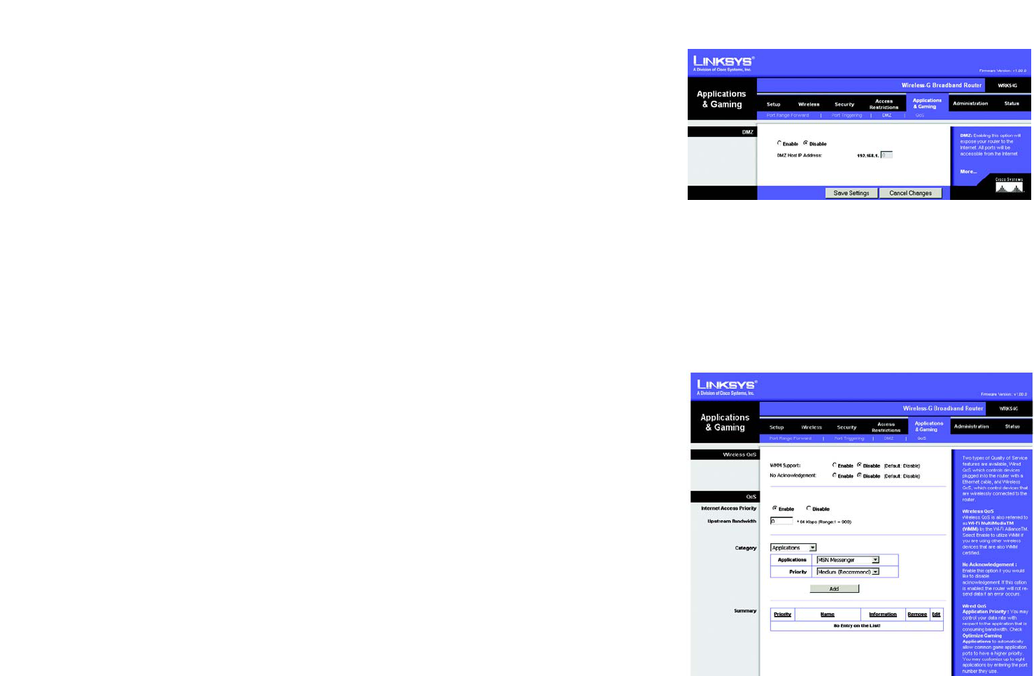
Figure 5-36: Applications and Gaming Tab - DMZ
The Applications and Gaming Tab - DMZ
The DMZ feature allows one network user to be exposed to the Internet for use of a special-purpose service such
as Internet gaming or videoconferencing. DMZ hosting forwards all the ports at the same time to one PC. The Port
Range Forward feature is more secure because it only opens the ports you want to have opened, while DMZ
hosting opens all the ports of one computer, exposing the computer to the Internet.
Any PC whose port is being forwarded must have its DHCP client function disabled and should have a new static
IP address assigned to it because its IP address may change when using the DHCP function.
To expose one PC, select Enable. Then, enter the computer's IP address in the DMZ Host IP Address field.
Change these settings as described here and click the Save Settings button to apply your changes or Cancel
Changes to cancel your changes.
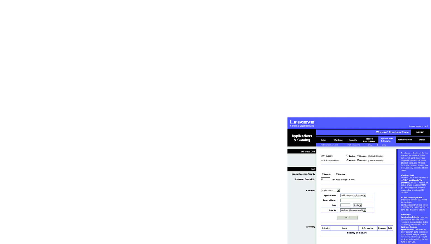
The Applications and Gaming Tab - QoS
Two types of Quality of Service (QoS) are available. Wireless QoS controls devices that are wirelessly
communicating with the Router. QoS controls devices plugged into the Router with an Ethernet cable.
Wireless QoS
WMM Support. Wireless QoS is also referred to as Wi-Fi Multi Media (WMM). Select Enable to utilize WMM if
you are using other wireless devices that are also WMM certified.
No Acknowledgement. Enable this option if you would like to disable acknowledgement. When enabled, the
Router will not resent data if an error occurs.
QoS
In this section, you can set priority based on a type of Category (such as an Application, Port Range, or MAC
Address). There are four priories you can set: High, Medium, Normal, or Low. Enable or Disable to set the Internet
Access priority.
Internet Access Priority. To limit outgoing bandwidth for the QoS policies in use, select Enable. Otherwise,
select Disable.
Upstream Bandwidth. This setting allows you to limit the outgoing bandwidth for the QoS policies in use, so you
can control how much bandwidth a particular application is allowed to use. Enter the bandwidth in the field. Figure 5-37: Applications and Gaming Tab - QOS
33
Chapter 5: Configuring the Wireless-G Broadband Router
The Applications and Gaming Tab - QoS
Wireless-G Broadband Router
Category. From this drop-down menu, you can select the Category for which you will set bandwidth priority.
These Categories include applications, ethernet ports, MAC addresses, and online games.
Application. With this option you can select None, Add a New Application, Online Game, or select from the
list of applications you want to set. To create a new entry, select Add a New Application, and refer to the
Add a New Application section.
Priority. Select the bandwidth priority for the application you selected. Select High, Medium, Normal, or
Low for the bandwidth you need for that application. Don’t set all applications to High, because this will
defeat the purpose of allocating the available bandwidth. If you want to select below normal bandwidth,
select Low. Depending on the application, a few attempts may be needed to achieve your goal. Once you
have made your selection, click Add to add to the Summary list.
Add a New Application
Enter a Name Enter any name to indicate the name of the entry.
Category Select from Port Range or MAC Address for the Router to use to set the bandwidth priority.
Port Range If you selected Port Range, then this category will be available. It allows you to enter the port
range that the application will be using. For example, if you want to allocate bandwidth for
FTP, you can enter 21-21. If you need services for an application that uses from 1000 to 1250,
you enter 1000-1250 as your settings. You can have up to three ranges to define for this
bandwidth allocation. Port numbers can range from 1 to 65535. Check your application's
documentation for details on the service ports used.
MAC Address If you selected MAC Address, then this category will be available. Enter the 12 hexadecimal
digit MAC Address to represent the device you want to set as a bandwidth priority. This is a
unique identifier for your network device. When the Router identifies the device entered, the
Router will allocate the priority set for that entry. Check the device’s documentation to obtain
the MAC Address.
Priority Select the bandwidth priority for the application you selected. Select High, Medium, Normal,
or Low for the bandwidth, but don’t set all applications to High. Once you have made your
selection, click Add to add to the Summary list. Figure 5-38: Applications and Gaming Tab - QOS
Adding an New Application

34
Chapter 5: Configuring the Wireless-G Broadband Router
The Applications and Gaming Tab - QoS
Wireless-G Broadband Router
Summary. This section will display a summary of all the categories of applications with QoS assigned.
Priority This displays the bandwidth allocation priority of High, Medium, Normal, or Low, that you set
for the application.
Name This displays the application name or the entries you entered to be allocated.
Information This displays the Port Range or MAC Address entered when you added a new application. If a
pre-configured application was selected, there will be no valid entry shown in this section.
Remove This button allows you to remove the application entry. To remove the entry, click the Remove
button.
Edit This button allows you to edit the application entry. To edit the entry, click the Edit button.
Change these settings as described here and click the Save Settings button to apply your changes or Cancel
Changes to cancel your changes.