LINKSYS WRT120N Wireless-N Home Router User Manual WRT120N User Guide
LINKSYS LLC Wireless-N Home Router WRT120N User Guide
LINKSYS >
Contents
- 1. Manual 1
- 2. Manual 2
Manual 1

USER GUIDE
Wireless-N Home Router
Model: WRT120N
About This Guide
i
Wireless-N Home Router
About This Guide
Icon Descriptions
While reading through the User Guide you may see
various icons that call attention to specific items. Below is
a description of these icons:
NOTE: This check mark indicates that there is
a note of interest and is something that you
should pay special attention to while using the
product.
WARNING: This exclamation point indicates
that there is a caution or warning and it is
something that could damage your property or
product.
WEB: This globe icon indicates a noteworthy
website address or e-mail address.
Online Resources
Website addresses in this document are listed without
http:// in front of the address because most current web
browsers do not require it. If you use an older web browser,
you may have to add http:// in front of the web address.
Resource Website
Linksys www.linksysbycisco.com
Linksys
International www.linksysbycisco.com/international
Glossary www.linksysbycisco.com/glossary
Network Security www.linksysbycisco.com/security
Copyright and Trademarks
Linksys, Cisco and the Cisco Logo are
registered trademarks or trademarks of
Cisco Systems, Inc. and/or its affiliates in
the U.S. and certain other countries. Other
brands and product names are trademarks
or registered trademarks of their respective
holders. Copyright © 2009 Cisco Systems,
Inc. All rights reserved.

Table of Contents
ii
Wireless-N Home Router
Chapter 1: Product Overview 1
Front Panel. . . . . . . . . . . . . . . . . . . . . . . . . . . . . . . . . . . . . . . . . . . . . . . . . . 1
Back Panel . . . . . . . . . . . . . . . . . . . . . . . . . . . . . . . . . . . . . . . . . . . . . . . . . . 1
Chapter 2: Wireless Security Checklist 3
General Network Security Guidelines . . . . . . . . . . . . . . . . . . . . . . . . . . . . . . . . . 3
Additional Security Tips . . . . . . . . . . . . . . . . . . . . . . . . . . . . . . . . . . . . . . . . . 3
Chapter 3: Advanced Conguration 4
Setup > Basic Setup . . . . . . . . . . . . . . . . . . . . . . . . . . . . . . . . . . . . . . . . . . . . 4
Setup > DDNS. . . . . . . . . . . . . . . . . . . . . . . . . . . . . . . . . . . . . . . . . . . . . . . . 8
Setup > MAC Address Clone. . . . . . . . . . . . . . . . . . . . . . . . . . . . . . . . . . . . . . . 9
Setup > Advanced Routing . . . . . . . . . . . . . . . . . . . . . . . . . . . . . . . . . . . . . . . 9
Wireless > Basic Wireless Settings . . . . . . . . . . . . . . . . . . . . . . . . . . . . . . . . . . .10
Wireless > Wireless Security . . . . . . . . . . . . . . . . . . . . . . . . . . . . . . . . . . . . . . .12
Wireless > Wireless MAC Filter. . . . . . . . . . . . . . . . . . . . . . . . . . . . . . . . . . . . . .14
Wireless > Advanced Wireless Settings . . . . . . . . . . . . . . . . . . . . . . . . . . . . . . . .15
Security > Firewall . . . . . . . . . . . . . . . . . . . . . . . . . . . . . . . . . . . . . . . . . . . . .16
Security > VPN Passthrough . . . . . . . . . . . . . . . . . . . . . . . . . . . . . . . . . . . . . . .17
Access Restrictions > Internet Access . . . . . . . . . . . . . . . . . . . . . . . . . . . . . . . . .17
Applications and Gaming > Single Port Forwarding. . . . . . . . . . . . . . . . . . . . . . . .19
Applications and Gaming > Port Range Forwarding . . . . . . . . . . . . . . . . . . . . . . .19
Applications & Gaming > Port Range Triggering . . . . . . . . . . . . . . . . . . . . . . . . . .20
Applications and Gaming > DMZ . . . . . . . . . . . . . . . . . . . . . . . . . . . . . . . . . . .20
Applications and Gaming > QoS . . . . . . . . . . . . . . . . . . . . . . . . . . . . . . . . . . . .21
Administration > Management. . . . . . . . . . . . . . . . . . . . . . . . . . . . . . . . . . . . .23
Administration > Log . . . . . . . . . . . . . . . . . . . . . . . . . . . . . . . . . . . . . . . . . . .24
Administration > Diagnostics . . . . . . . . . . . . . . . . . . . . . . . . . . . . . . . . . . . . . .24
Administration > Factory Defaults . . . . . . . . . . . . . . . . . . . . . . . . . . . . . . . . . . .25
Administration > Firmware Upgrade . . . . . . . . . . . . . . . . . . . . . . . . . . . . . . . . .25
Status > Router . . . . . . . . . . . . . . . . . . . . . . . . . . . . . . . . . . . . . . . . . . . . . . .26
Status > Local Network . . . . . . . . . . . . . . . . . . . . . . . . . . . . . . . . . . . . . . . . . .26
Status > Wireless Network . . . . . . . . . . . . . . . . . . . . . . . . . . . . . . . . . . . . . . . .27
Appendix A: Troubleshooting 28
Appendix B: Specications 29
Appendix C: Warranty Information 30
Limited Warranty. . . . . . . . . . . . . . . . . . . . . . . . . . . . . . . . . . . . . . . . . . . . . .30

Table of Contents
iii
Wireless-N Home Router
Appendix D: Regulatory Information 32
FCC Statement . . . . . . . . . . . . . . . . . . . . . . . . . . . . . . . . . . . . . . . . . . . . . . .32
FCC Radiation Exposure Statement . . . . . . . . . . . . . . . . . . . . . . . . . . . . . . . . . .32
Safety Notices. . . . . . . . . . . . . . . . . . . . . . . . . . . . . . . . . . . . . . . . . . . . . . . .32
Industry Canada Statement . . . . . . . . . . . . . . . . . . . . . . . . . . . . . . . . . . . . . . .32
Avis d’Industrie Canada. . . . . . . . . . . . . . . . . . . . . . . . . . . . . . . . . . . . . . . . . .33
Wireless Disclaimer . . . . . . . . . . . . . . . . . . . . . . . . . . . . . . . . . . . . . . . . . . . .33
Avis de non-responsabilité concernant les appareils sans fil . . . . . . . . . . . . . . . . . .33
User Information for Consumer Products Covered by EU Directive 2002/96/EC on Waste
Electric and Electronic Equipment (WEEE) . . . . . . . . . . . . . . . . . . . . . . . . . . . . . .34
Appendix E: Software End User License Agreement 38
Cisco Products . . . . . . . . . . . . . . . . . . . . . . . . . . . . . . . . . . . . . . . . . . . . . . .38
Software Licenses . . . . . . . . . . . . . . . . . . . . . . . . . . . . . . . . . . . . . . . . . . . . .38
Chapter 1 Product Overview
1
Wireless-N Home Router
Chapter 1:
Product Overview
Thank you for choosing the Linksys by Cisco Wireless-N
Home Router. The Router lets you access the Internet via
a wireless connection or through one of its four switched
ports. You can also use the Router to share resources
such as computers, printers and files. A variety of security
features help to protect your data and your privacy
while you are online. Security features include WPA2
security, a Stateful Packet Inspection (SPI) firewall, and
NAT technology. Configuring the Router is easy using the
provided browser–based utility.
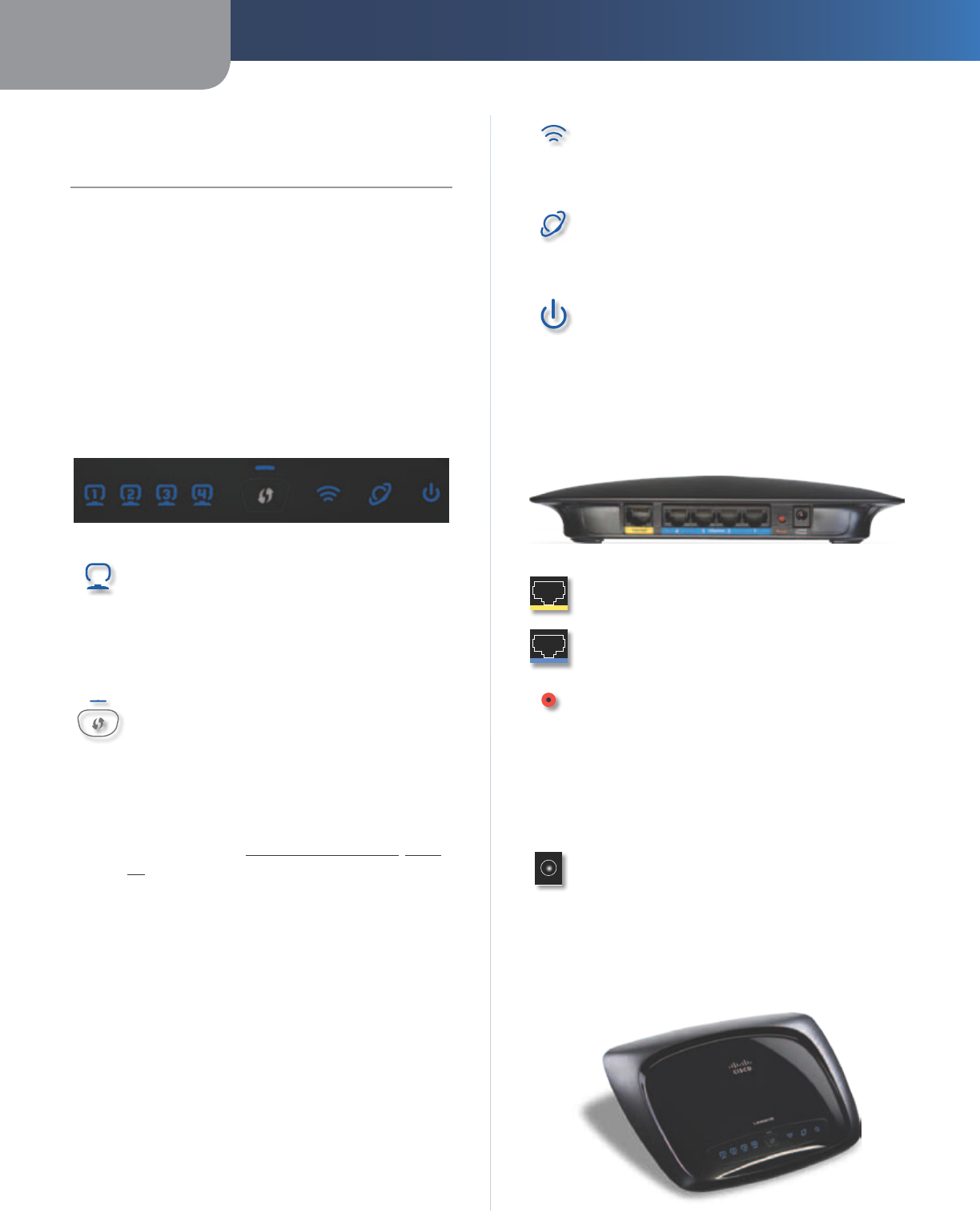
Front Panel
1, 2, 3, 4 (Blue) These numbered LEDs,
corresponding with the numbered ports on the
Router’s back panel, serve two purposes. If the
LED is continuously lit, the Router is successfully
connected to a device through that port. A
flashing LED indicates network activity over
that port.
Wi-Fi Protected Setup Button If you have
client devices, such as wireless adapters, that
support Wi-Fi Protected Setup, then you can
use Wi-Fi Protected Setup to automatically
configure wireless security for your wireless
network.
To use Wi-Fi Protected Setup, run the Setup
Wizard, or refer to Wi-Fi Protected Setup, page
11.
Wi-Fi Protected Setup LED (Blue/
Amber) The LED lights up blue when wireless
security is enabled. It flashes blue for two
minutes during Wi-Fi Protected Setup.
The LED lights up amber if there is an error
during the Wi-Fi Protected Setup process. Make
sure the client device supports Wi-Fi Protected
Setup. Wait until the LED is off, and then try again.
The LED flashes when a Wi-Fi Protected Setup
session is active. The Router supports one
session at a time. Wait until the LED is solidly lit,
or off before starting the next Wi-Fi Protected
Setup session.
Wireless (Blue) The Wireless LED lights up
when the wireless feature is enabled. If the LED
is flashing, the Router is sending or receiving
data over the network.
Internet (Blue) The Internet LED lights up
when there is a connection made through the
Internet port. It flashes to indicate network
activity over the Internet port.
Power (Blue) The Power LED lights up and will
stay on while the Router is powered on. When
the Router goes through its self-diagnostic
mode during every boot-up, this LED will flash.
When the diagnostic is complete, the LED will
be solidly lit.
Back Panel
Internet The Internet port is where you will
connect your cable or DSL Internet connection.
4, 3, 2, 1 These Ethernet ports (4, 3, 2, 1)
connect the Router to computers on your wired
network and other Ethernet network devices.
Reset The Reset button is located on the
right side of the product label. There are two
ways to reset the Router to its factory defaults.
Either press and hold the Reset button for
approximately five seconds, or restore the
defaults from the Administration > Factory
Defaults screen of the Router’s browser-based
utility.
Power The Power port connects to the included
power adapter.
Horizontal Placement
The Router has four rubber feet on its bottom panel. Place
the Router on a level surface near an electrical outlet.
Chapter 1 Product Overview
2
Wireless-N Home Router
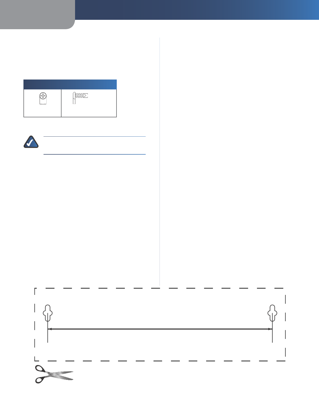
Wall-Mounting Placement
The Router has two wall-mount slots on its bottom
panel. The distance between the slots is 152 mm
(6 inches).
Two screws are needed to mount the Router.
Suggested Mounting Hardware
2.5-3.0 mm
4-5 mm 1-1.5 mm
†Note: Mounting hardware illustrations are not
true to scale.
NOTE: Linksys is not responsible for damages
incurred by insecure wall-mounting hardware.
Follow these instructions:
1. Determine where you want to mount the Router. Make
sure that the wall you use is smooth, flat, dry, and
sturdy. Also make sure the location is within reach of
an electrical outlet.
2. Drill two holes into the wall. Make sure the holes are
152 mm (6 inches) apart.
3. Insert a screw into each hole and leave 3 mm
(0.12 inches) of its head exposed.
4. Maneuver the Router so the wall-mount slots line up
with the two screws.
5. Place the wall-mount slots over the screws and slide
the Router down until the screws fit snugly into the
wall-mount slots.
152 mm
Wall-Mounting Template
Print this page at 100% size.
Cut along the dotted line, and place on the wall to drill precise spacing.

Chapter 2 Wireless Security Checklist
3
Wireless-N Home Router
Chapter 2:
Wireless Security Checklist
Wireless networks are convenient and easy to install, so
homes with high-speed Internet access are adopting them
at a rapid pace. Because wireless networking operates by
sending information over radio waves, it can be more
vulnerable to intruders than a traditional wired network.
Like signals from your cellular or cordless phones, signals
from your wireless network can also be intercepted. Since
you cannot physically prevent someone from connecting
to your wireless network, you need to take some additional
steps to keep your network secure.
1. Change the default wireless
network name or SSID
Wireless devices have a default wireless network name
or Service Set Identifier (SSID) set by the factory. This
is the name of your wireless network, and can be up
to 32 characters in length. Linksys wireless products
use linksys as the default wireless network name. You
should change the wireless network name to something
unique to distinguish your wireless network from other
wireless networks that may exist around you, but do not
use personal information (such as your Social Security
number) because this information may be available for
anyone to see when browsing for wireless networks.
2. Change the default password
For wireless products such as access points and routers,
you will be asked for a password when you want to change
their settings. These devices have a default password set
by the factory. The Linksys default password is admin.
Hackers know these defaults and may try to use them
to access your wireless device and change your network
settings. To thwart any unauthorized changes, customize
the device’s password so it will be hard to guess.
3. Enable MAC address filtering
Linksys routers give you the ability to enable Media Access
Control (MAC) address filtering. The MAC address is a
unique series of numbers and letters assigned to every
networking device. With MAC address filtering enabled,
wireless network access is provided solely for wireless
devices with specific MAC addresses. For example, you can
specify the MAC address of each computer in your home
so that only those computers can access your wireless
network.
4. Enable encryption
Encryption protects data transmitted over a wireless
network. Wi-Fi Protected Access (WPA/WPA2) and Wired
Equivalent Privacy (WEP) offer different levels of security
for wireless communication.
A network encrypted with WPA/WPA2 is more secure
than a network encrypted with WEP, because WPA/WPA2
uses dynamic key encryption. To protect the information
as it passes over the airwaves, you should enable the
highest level of encryption supported by your network
equipment.
WEP is an older encryption standard and may be the
only option available on some older devices that do not
support WPA.
General Network Security Guidelines
Wireless network security is useless if the underlying
network is not secure.
•Password protect all computers on the network and
individually password protect sensitive files.
•Change passwords on a regular basis.
•Install anti-virus software and personal firewall
software.
•Disable file sharing (peer-to-peer). Some applications
may open file sharing without your consent and/or
knowledge.
Additional Security Tips
•Keep wireless routers, access points, or gateways away
from exterior walls and windows.
•Turn wireless routers, access points, or gateways
off when they are not being used (at night, during
vacations).
•Use strong passphrases that are at least eight characters
in length. Combine letters and numbers to avoid using
standard words that can be found in the dictionary.
WEB: For more information on wireless security,
visit www.linksysbycisco.com/security
Chapter 3 Advanced Configuration
4
Wireless-N Home Router
Chapter 3:
Advanced Configuration
After setting up the Router with the Setup Wizard (located
on the CD-ROM), the Router will be ready for use. However,
if you want to change its advanced settings, use the
Router’s browser-based utility. This chapter describes each
web page of the utility and each page’s key functions. You
can access the utility via a web browser on a computer
connected to the Router.
The browser-based utility has these main tabs: Setup,
Wireless, Security, Access Restrictions, Applications &
Gaming, Administration, and Status. Additional tabs will
be available after you click one of the main tabs.
NOTE: When first installing the Router, you
should use the Setup Wizard on the Setup
CD-ROM. If you want to configure advanced
settings, use this chapter to learn about the
browser-based utility.
Access the Browser-Based Utility
To access the browser-based utility, launch the web
browser on your computer, and enter the Router’s default
IP address, 192.168.1.1, in the Address field. Then press
Enter.
A login screen will appear. (Non-Windows XP users will
see a similar screen.) Leave the User name field blank.
The first time you open the browser-based utility, use the
default password admin. (You can set a new password
from the Administration > Management screen.) Click OK
to continue.
Login Screen
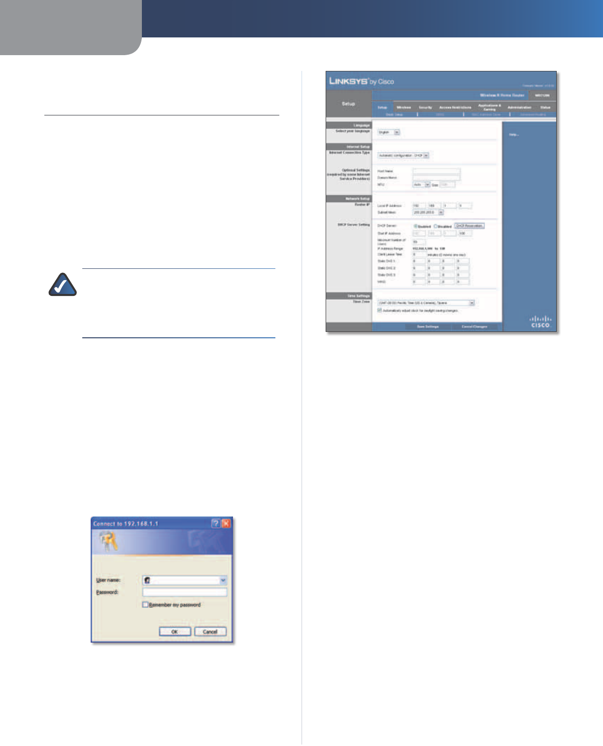
Setup > Basic Setup
The first screen that appears is the Basic Setup screen. This
allows you to change the Router’s general settings.
Setup > Basic Setup
Language
Select your language
To use a different language, select
one from the drop-down menu. The language of the
browser-based utility will change five seconds after you
select another language.
Click Save Settings to apply your changes, or click Cancel
Changes to clear your changes.
Internet Setup
The Internet Setup section configures the Router to your
Internet connection. Most of this information can be
obtained through your Internet Service Provider (ISP).
Internet Connection Type
Select the type of Internet connection your ISP provides
from the drop-down menu. These are the available types:
•Automatic Configuration - DHCP
•Static IP
•PPPoE
•PPTP
•L2TP
•Telstra Cable
Chapter 3 Advanced Configuration
5
Wireless-N Home Router
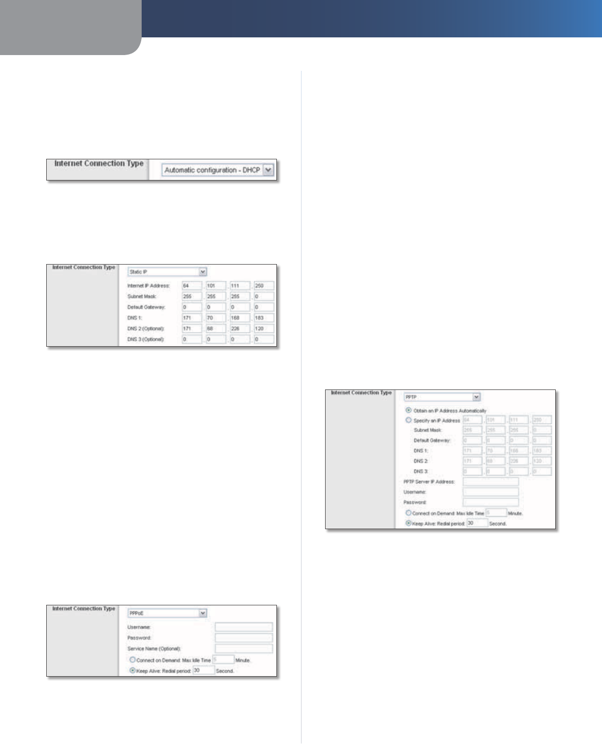
Automatic Configuration - DHCP
By default, the Router’s Internet Connection Type is set
to Automatic configuration - DHCP, which should be
kept only if your ISP supports DHCP or you are connecting
through a dynamic IP address. (This option usually applies
to cable connections.)
Internet Connection Type > Automatic Configuration - DHCP
Static IP
If you are required to use a permanent IP address to
connect to the Internet, select Static IP.
Internet Connection Type > Static IP
Internet IP Address This is the Router’s IP address, when
seen from the Internet. Your ISP will provide you with the
IP Address you need to specify here.
Subnet Mask This is the Router’s Subnet Mask, as seen
by users on the Internet (including your ISP). Your ISP will
provide you with the Subnet Mask.
Default Gateway Your ISP will provide you with the IP
address of the ISP server.
DNS 1-3 Your ISP will provide you with at least one DNS
(Domain Name System) server IP address.
PPPoE
Some DSL-based ISPs use PPPoE (Point-to-Point Protocol
over Ethernet) to establish Internet connections. If you are
connected to the Internet through a DSL line, check with
your ISP to see if they use PPPoE. If they do, you will have
to enable PPPoE.
Internet Connection Type > PPPoE
Username and Password Enter the Username and
Password provided by your ISP.
Service Name (Optional) If provided by your ISP, enter
the Service Name.
Connect on Demand: Max Idle Time You can configure
the Router to cut the Internet connection after it has been
inactive for a specified period of time (Max Idle Time). If
your Internet connection has been terminated due to
inactivity, Connect on Demand enables the Router to
automatically re-establish your connection as soon as you
attempt to access the Internet again. To use this option,
select Connect on Demand. In the Max Idle Time field,
enter the number of minutes you want to have elapsed
before your Internet connection terminates. The default
Max Idle Time is 5 minutes.
Keep Alive: Redial Period If you select this option,
the Router will periodically check your Internet
connection. If you are disconnected, then the Router
will automatically re-establish your connection. To use
this option, select Keep Alive. In the Redial Period field,
you specify how often you want the Router to check
the Internet connection. The default Redial Period is
30 seconds.
PPTP
Point-to-Point Tunneling Protocol (PPTP) is a service that
applies to connections in Europe only.
Internet Connection Type > PPTP
If your ISP supports DHCP or you are connecting through
a dynamic IP address, then select Obtain an IP Address
Automatically. If you are required to use a permanent IP
address to connect to the Internet, then select Specify an
IP Address. Then configure the following:
•Specify an IP Address This is the Router’s IP address,
as seen from the Internet. Your ISP will provide you
with the IP Address you need to specify here.
•Subnet Mask This is the Router’s Subnet Mask, as
seen by users on the Internet (including your ISP). Your
ISP will provide you with the Subnet Mask.
•Default Gateway Your ISP will provide you with the
IP address of the ISP server.
Chapter 3 Advanced Configuration
6
Wireless-N Home Router
•DNS 1-3 Your ISP will provide you with at least one
DNS (Domain Name System) server IP address.
PPTP Server IP Address Your ISP will provide you with
the IP address of the PPTP server.
Username and Password Enter the Username and
Password provided by your ISP.
Connect on Demand: Max Idle Time You can configure
the Router to cut the Internet connection after it has been
inactive for a specified period of time (Max Idle Time). If
your Internet connection has been terminated due to
inactivity, Connect on Demand enables the Router to
automatically re-establish your connection as soon as you
attempt to access the Internet again. To use this option,
select Connect on Demand. In the Max Idle Time field,
enter the number of minutes you want to have elapsed
before your Internet connection terminates. The default
Max Idle Time is 5 minutes.
Keep Alive: Redial Period
If you select this option, the
Router will periodically check your Internet connection. If
you are disconnected, then the Router will automatically
re-establish your connection. To use this option, select
Keep Alive. In the Redial Period field, you specify how often
you want the Router to check the Internet connection. The
default value is 30 seconds.
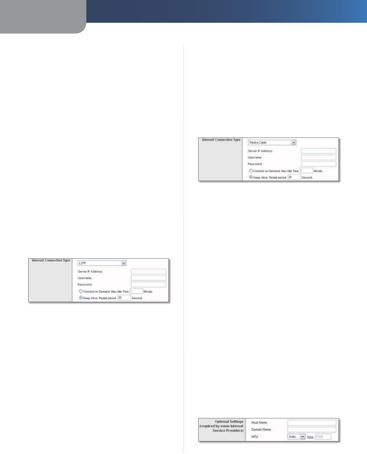
L2TP
L2TP is a service that applies to connections in Israel only.
Internet Connection Type > L2TP
Server IP Address This is the IP address of the L2TP
Server. Your ISP will provide you with the IP Address you
need to specify here.
Username and Password Enter the Username and
Password provided by your ISP.
Connect on Demand: Max Idle Time You can configure
the Router to cut the Internet connection after it has been
inactive for a specified period of time (Max Idle Time). If
your Internet connection has been terminated due to
inactivity, Connect on Demand enables the Router to
automatically re-establish your connection as soon as you
attempt to access the Internet again. To use this option,
select Connect on Demand. In the Max Idle Time field,
enter the number of minutes you want to have elapsed
before your Internet connection terminates. The default
Max Idle Time is 5 minutes.
Keep Alive: Redial Period If you select this option,
the Router will periodically check your Internet
connection. If you are disconnected, then the Router
will automatically re-establish your connection. To use
this option, select Keep Alive. In the Redial Period field,
you specify how often you want the Router to check
the Internet connection. The default Redial Period is
30 seconds.
Telstra Cable
Telstra Cable is a service that applies to connections in
Australia only.
Internet Connection Type > Telstra Cable
Server IP Address This is the IP address of the Heartbeat
Server. Your ISP will provide you with the IP Address you
need to specify here.
Username and Password Enter the Username and
Password provided by your ISP.
Connect on Demand: Max Idle Time You can configure
the Router to cut the Internet connection after it has been
inactive for a specified period of time (Max Idle Time). If
your Internet connection has been terminated due to
inactivity, Connect on Demand enables the Router to
automatically re-establish your connection as soon as you
attempt to access the Internet again. To use this option,
select Connect on Demand. In the Max Idle Time field,
enter the number of minutes you want to have elapsed
before your Internet connection terminates. The default
Max Idle Time is 5 minutes.
Keep Alive: Redial Period If you select this option,
the Router will periodically check your Internet
connection. If you are disconnected, then the Router
will automatically re-establish your connection. To use
this option, select Keep Alive. In the Redial Period field,
you specify how often you want the Router to check
the Internet connection. The default Redial Period is
30 seconds.
Optional Settings
Some of these settings may be required by your ISP. Verify
with your ISP before making any changes.
Optional Settings
Chapter 3 Advanced Configuration
7
Wireless-N Home Router
Host Name and Domain Name These fields allow you to
supply a host and domain name for the Router. Some ISPs,
usually cable ISPs, require these names as identification.
You may have to check with your ISP to see if your
broadband Internet service has been configured with a
host and domain name. In most cases, leaving these fields
blank will work.
MTU MTU is the Maximum Transmission Unit. It specifies
the largest packet size permitted for Internet transmission.
Select Manual if you want to manually enter the largest
packet size that is transmitted. To have the Router select
the best MTU for your Internet connection, keep the
default, Auto.
Size When Manual is selected in the MTU field, this option
is enabled. Leave this value in the 1200 to 1500 range. The
default size depends on the Internet Connection Type:
•DHCP, Static IP, or Telstra: 1500
•PPPoE: 1492
•PPTP or L2TP: 1460
Network Setup
The Network Setup section changes the settings of the
local network. Wireless setup is performed through the
Wireless tab.
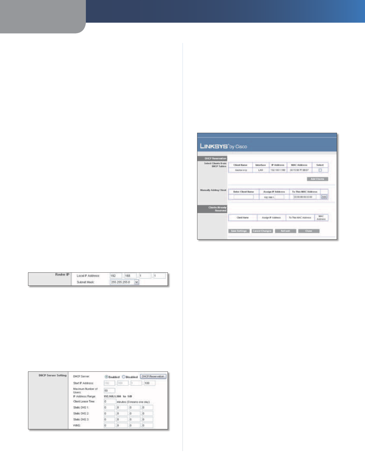
Router IP
This presents both the Router’s Local IP Address and
Subnet Mask as seen by your network.
Router IP
DHCP Server Setting
The settings allow you to configure the Router’s Dynamic
Host Configuration Protocol (DHCP) server function. The
Router can be used as a DHCP server for your network. A
DHCP server automatically assigns an IP address to each
computer on your network. If you choose to enable the
Router’s DHCP server option, make sure there is no other
DHCP server on your network.
DHCP Server Setting
DHCP Server DHCP is enabled by factory default. If you
already have a DHCP server on your network, or you do
not want a DHCP server, then select Disabled (no other
DHCP features will be available).
DHCP Reservation Click this button if you want to assign
a fixed local IP address to a MAC address.
DHCP Reservation
You will see a list of DHCP clients with the following
information: Client Name, Interface, IP Address, and
MAC Address.
DHCP Reservation
•Select Clients from DHCP Table Click the Select
check box to reserve a client’s IP address. Then click
Add Clients.
•Manually Adding Client To manually assign an IP
address, enter the client’s name in the Enter Client
Name field. Enter the IP address you want it to have in
the Assign IP Address field. Enter its MAC address in the
To This MAC Address field. Then click Add.
Clients Already Reserved
A list of DHCP clients and their fixed local IP addresses
will be displayed at the bottom of the screen. If you
want to remove a client from this list, click Remove.
Click Save Settings to apply your changes, or click
Cancel Changes to clear your changes. To update the
on-screen information, click Refresh. To exit this screen
and return to the Basic Setup screen, click Close.
Start IP Address Enter a value for the DHCP server to
start with when is
suing IP addresses. Because the Router’s
default IP address is 192.168.1.1, the Start IP Address must
be 192.168.1.2 or greater, but smaller than 192.168.1.253.
The default is 192.168.1.100
.
Maximum Number of Users Enter the maximum number
of computers that you want the DHCP server to assign IP
Chapter 3 Advanced Configuration
8
Wireless-N Home Router
addresses to. This number cannot be greater than 253.
The default is 50.
IP Address Range Displayed here is the range of available
IP addresses.
Client Lease Time The Client Lease Time is the amount
of time a network user will be allowed connection to the
Router with their current dynamic IP address. Enter the
amount of time, in minutes, that the user will be “leased”
this dynamic IP address. After the time has expired, the
user will be automatically assigned a new dynamic IP
address, or the lease will be renewed. The default is 0
minutes, which means one day.
Static DNS 1-3
The Domain Name System (DNS) is how
the Internet translates domain or website names into
Internet addresses or URLs. Your ISP will provide you with at
least one DNS Server IP Address. If you wish to use another,
enter that IP Address in one of these fields. You can enter up
to three DNS Server IP Addresses here. The Router will use
these for quicker access to functioning DNS servers
.
WINS The Windows Internet Naming Service (WINS)
manages each computer’s interaction with the Internet. If
you use a WINS server, enter that server’s IP Address here.
Otherwise, leave this blank.
Time Settings
Time Zone Select the time zone in which your network
functions from this drop-down menu. (You can even
automatically adjust for daylight saving time.)
Time Settings
Click Save Settings to apply your changes, or click Cancel
Changes to clear your changes.
Setup > DDNS
The Router offers a Dynamic Domain Name System (DDNS)
feature. DDNS lets you assign a fixed host and domain
name to a dynamic Internet IP address. It is useful when
you are hosting your own website, FTP server, or other
server behind the Router.
Before you can use this feature, you need to sign
up for DDNS service with a DDNS service provider,
www.dyndns.org or www.TZO.com. If you do not want
to use this feature, keep the default, Disabled.
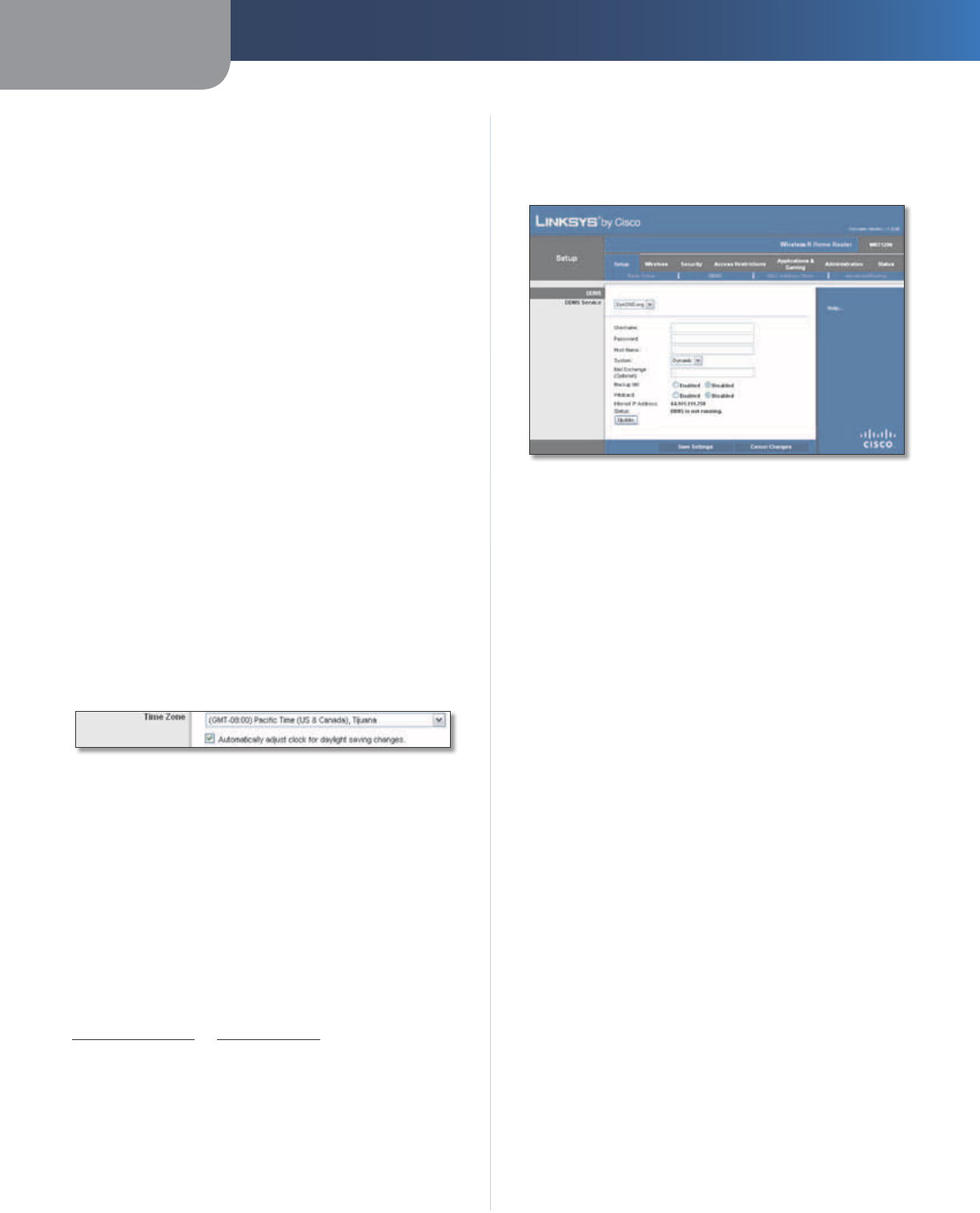
DDNS
DDNS Service
If your DDNS service is provided by DynDNS.org, then
select DynDNS.org from the drop-down menu. If your
DDNS service is provided by TZO, then select TZO.com.
The features available on the DDNS screen will vary,
depending on which DDNS service provider you use.
DynDNS.org
Setup > DDNS > DynDNS
Username Enter the Username for your DDNS account.
Password Enter the Password for your DDNS account.
Host Name The is the DDNS URL assigned by the DDNS
service.
System Select the DynDNS service you use: Dynamic,
Static, or Custom. The default selection is Dynamic.
Mail Exchange (Optional) Enter the address of your mail
exchange server, so e-mails to your DynDNS address go to
your mail server.
Backup MX This feature allows the mail exchange server
to be a backup. To disable this feature, keep the default,
Disabled. To enable the feature, select Enabled. If you
are not sure which setting to select, keep the default,
Disabled.
Wildcard This setting enables or disables wildcards
for your host. For example, if your DDNS address is
myplace.dyndns.org and you enable wildcards, then
x.myplace.dyndns.org will work as well (x is the wildcard).
To disable wildcards, keep the default, Disabled. To enable
wildcards, select Enabled. If you are not sure which setting
to select, keep the default, Disabled.
Internet IP Address The Router’s Internet IP address is
displayed here. Because it is dynamic, it will change.
Status The status of the DDNS service connection is
displayed here.
Update To manually trigger an update, click this button.
Click Save Settings to apply your changes, or click Cancel
Changes to clear your changes.
Chapter 3 Advanced Configuration
9
Wireless-N Home Router
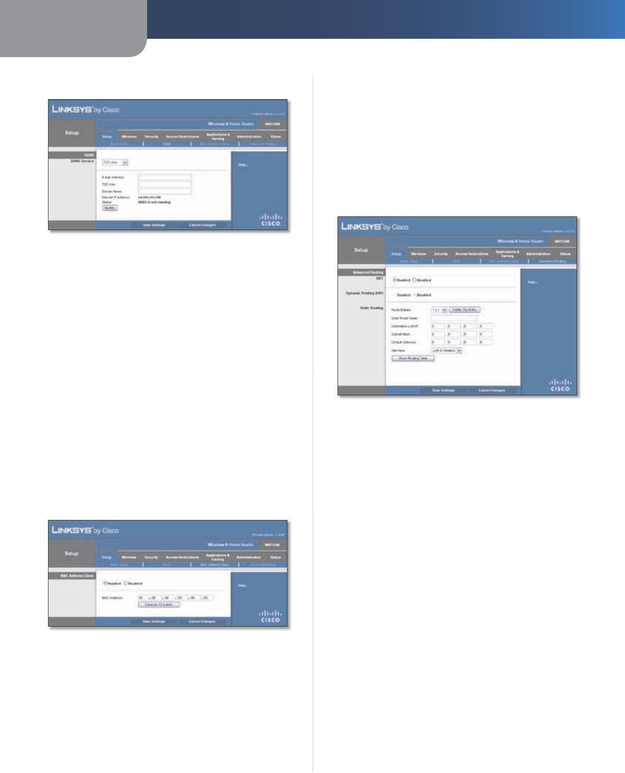
TZO.com
Setup > DDNS > TZO
E-mail Address, TZO Key, and Domain Name Enter the
settings of the account you set up with TZO.
Internet IP Address The Router’s Internet IP address is
displayed here. Because it is dynamic, it will change.
Status The status of the DDNS service connection is
displayed here.
Update To manually trigger an update, click this button.
Click Save Settings to apply your changes, or click Cancel
Changes to clear your changes.
Setup > MAC Address Clone
A MAC address is a 12-digit code assigned to a unique
piece of hardware for identification. Some ISPs will require
you to register a MAC address in order to access the
Internet. If you do not wish to re-register the MAC address
with your ISP, you may assign the MAC address you have
currently registered with your ISP to the Router with the
MAC Address Clone feature.
Setup > MAC Address Clone
MAC Address Clone
Enabled/Disabled To have the MAC Address cloned,
select Enabled.
MAC Address Enter the MAC Address registered with
your ISP here.
Clone My PC’s MAC Click this button to clone the MAC
address of the computer you are using.
Click Save Settings to apply your changes, or click Cancel
Changes to clear your changes.
Setup > Advanced Routing
This screen is used to set up the Router’s advanced
functions. Operating Mode allows you to select the
type(s) of advanced functions you use. Dynamic Routing
automatically adjusts how packets travel on your network.
Static Routing sets up a fixed route to another network
destination.
Setup > Advanced Routing
Advanced Routing
NAT
Enabled/Disabled If this Router is hosting your network’s
connection to the Internet, keep the default, Enabled. If
another router exists on your network, select Disabled.
When the NAT setting is disabled, dynamic routing will be
enabled.
Dynamic Routing (RIP)
Enabled/Disabled This feature enables the Router to
automatically adjust to physical changes in the network’s
layout and exchange routing tables with the other router(s).
The Router determines the network packets’ route based
on the fewest number of hops between the source and
the destination. When the NAT setting is enabled, the
Dynamic Routing feature is automatically disabled. When
the NAT setting is disabled, this feature is available. Select
Enabled to use the Dynamic Routing feature.
Static Routing
A static route is a pre-determined pathway that network
information must travel to reach a specific host or network.
Enter the information described below to set up a new
static route.
Chapter 3 Advanced Configuration
10
Wireless-N Home Router
Route Entries To set up a static route between the Router
and another network, select a number from the drop-
down list. Click Delete This Entry to delete a static route.
Enter Route Name Enter a name for the Route here,
using a maximum of 25 alphanumeric characters.
Destination LAN IP The Destination LAN IP is the address
of the remote network or host to which you want to assign
a static route.
Subnet Mask The Subnet Mask determines which
portion of a Destination LAN IP address is the network
portion, and which portion is the host portion.
Default Gateway This is the IP address of the gateway
device that allows for contact between the Router and the
remote network or host.
Interface This interface tells you whether the Destination
IP Address is on the LAN & Wireless (Ethernet and wireless
networks) or the WAN (Internet).
Click Show Routing Table to view the static routes you
have already set up.
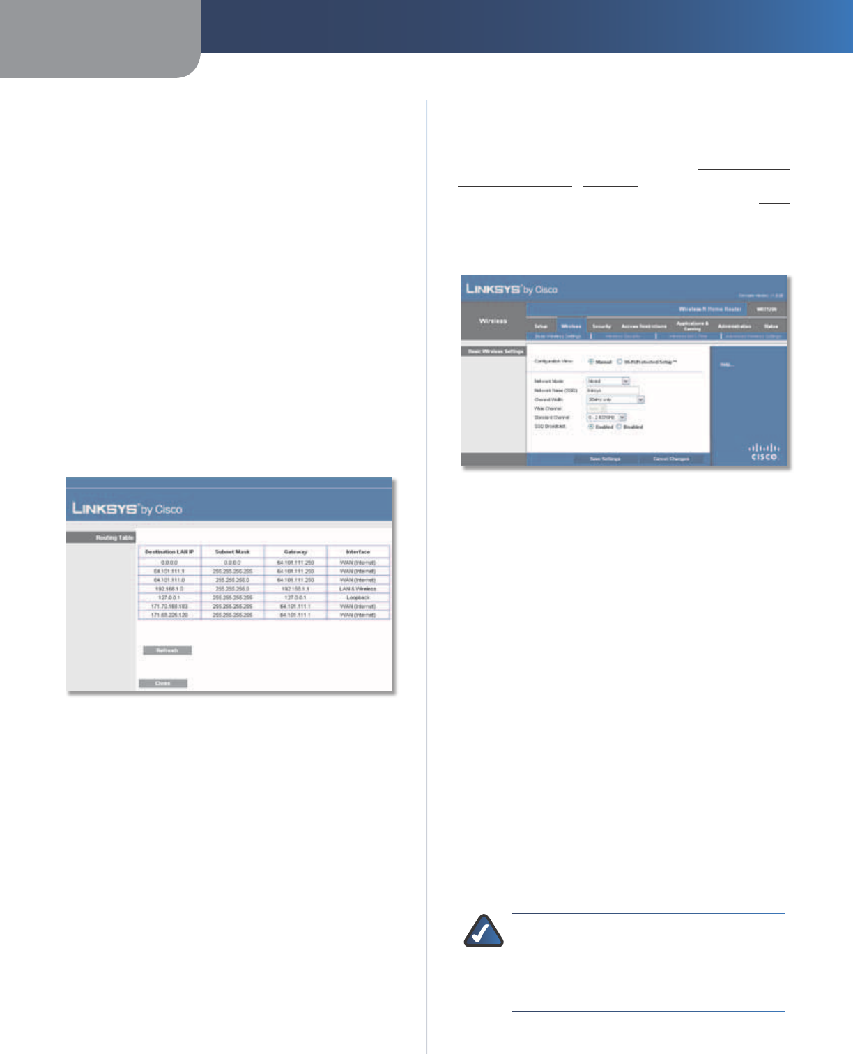
Advanced Routing > Routing Table
Routing Table
For each route, the Destination LAN IP address, Subnet
Mask, Gateway, and Interface are displayed. To update
the information, click Refresh. To exit this screen and
return to the Advanced Routing screen, click Close.
Click Save Settings to apply your changes, or click Cancel
Changes to clear your changes.
Wireless > Basic Wireless Settings
The basic settings for wireless networking are set on this
screen.
There are two ways to configure the Router’s wireless
network(s), manual and Wi-Fi Protected Setup.
Wi-Fi Protected Setup is a feature that makes it easy to set
up your wireless network. If you have client devices, such
as wireless adapters, that support Wi-Fi Protected Setup,
then you can use Wi-Fi Protected Setup.
Configuration View To manually configure your wireless
network, select Manual. Proceed to Basic Wireless
Settings (Manual), page 10. To use Wi-Fi Protected
Setup, select Wi-Fi Protected Setup. Proceed to Wi-Fi
Protected Setup, page 11.
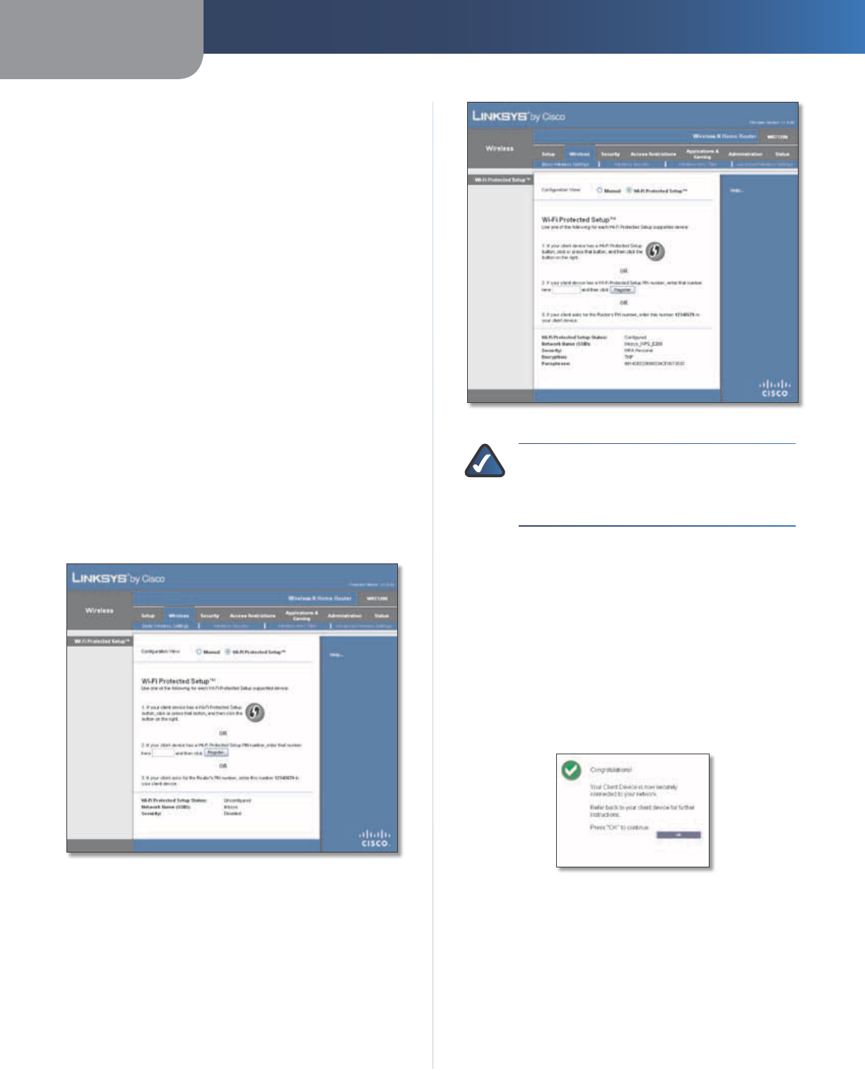
Basic Wireless Settings (Manual)
Wireless > Basic Wireless Settings (Manual Setup)
Network Mode From this drop-down menu, you can
select the wireless standards running on your network. If
you have Wireless-N, Wireless-G, and Wireless-B devices in
your network, keep the default, Mixed. If you have only
Wireless-G and Wireless-B devices in your network, select
BG-Mixed. If you have only Wireless-N devices, select
Wireless-N Only. If you have only Wireless-G devices,
select Wireless-G Only. If you have only Wireless-B
devices, select Wireless-B Only. If you do not have any
wireless devices in your network, select Disabled.
Network Name (SSID) The SSID is the network name
shared among all points in a wireless network. The
SSID must be identical for all devices in the wireless
network. It is case-sensitive and must not exceed
32 characters (use any of the characters on the keyboard).
Make sure this setting is the same for all points in your
wireless network. For added security, you should change
the default SSID (linksys) to a unique name.
Channel Width For best performance in a Wireless-N
network, select 40MHz only. For Wireless-G and Wireless-B
networking only, keep the default, 20MHz only. If you
are not sure which option to use, select Auto (20MHz or
40MHz).
NOTE: If you select 40MHz only for the Channel
Width setting, then Wireless-N can use two
channels: a primary one (Wide Channel) and
a secondary one (Standard Channel). This will
enhance Wireless-N performance.
Wide Channel If 40MHz only is the Channel Width
setting, then this setting will be available for your primary
Chapter 3 Advanced Configuration
11
Wireless-N Home Router
Wireless-N channel. Select any channel from the drop-
down menu. If you are not sure which channel to select,
keep the default, Auto.
Standard Channel If 20MHz only is the Channel Width
setting, then select the appropriate channel for your
wireless network. If you are not sure which channel to
select, then keep the default, Auto.
If 40MHz only is the Channel Width setting, then the
Standard Channel will be a secondary channel for
Wireless-N (2.4 GHz). If you selected a specific channel
for the Wide Channel setting, then the Standard Channel
options will be available. Select the appropriate channel
for your wireless network.
SSID Broadcast When wireless clients survey the local
area for wireless networks to associate with, they will
detect the SSID broadcast by the Router. To broadcast the
Router’s SSID, keep the default, Enabled. If you do not want
to broadcast the Router’s SSID, then select Disabled.
Click Save Settings to apply your changes, or click Cancel
Changes to clear your changes.
Wi-Fi Protected Setup
There are three methods available. Use the method that
applies to the client device you are configuring.
Wireless > Basic Wireless Settings (Wi-Fi Protected Setup)
Wi-Fi Protected Setup Configured
NOTE: Wi-Fi Protected Setup configures one
client device at a time. Repeat the instructions
for each client device that supports Wi-Fi
Protected Setup.
Method #1
Use this method if your client device has a Wi-Fi Protected
Setup button.
1. Click or press the Wi-Fi Protected Setup button on
the client device.
2. Click the Wi-Fi Protected Setup button on this
screen.
3. After the client device has been configured, click
OK. Then refer back to your client device or its
documentation for further instructions.
Wi-Fi Protected Setup > Congratulations
Method #2
Use this method if your client device has a Wi-Fi Protected
Setup PIN number.
1. Enter the PIN number in the field on this screen.
2. Click Register.
3. After the client device has been configured, click
OK. Then refer back to your client device or its
documentation for further instructions.
Chapter 3 Advanced Configuration
12
Wireless-N Home Router
Method #3
Use this method if your client device asks for the Router’s
PIN number.
1. Enter the PIN number listed on this screen. (It is also
listed on the label on the bottom of the Router.)
2. After the client device has been configured, click
OK. Then refer back to your client device or its
documentation for further instructions.
The Wi-Fi Protected Setup Status, Network Name (SSID),
Security, Encryption, and Passphrase are displayed at the
bottom of the screen.
NOTE: If you have client devices that do not
support Wi-Fi Protected Setup, note the wireless
settings, and then manually configure those
client devices.
Wireless > Wireless Security
The Wireless Security screen configures the security of
your wireless network. There are six wireless security
mode options supported by the Router: WPA Personal,
WPA Enterprise, WPA2 Personal, WPA2 Enterprise, RADIUS,
and WEP. (WPA stands for Wi-Fi Protected Access, which
is a security standard stronger than WEP encryption. WEP
stands for Wired Equivalent Privacy, while RADIUS stands
for Remote Authentication Dial-In User Service.) These
six are briefly discussed here. For detailed instructions
on configuring wireless security for the Router, refer to
Chapter 2: Wireless Security Checklist, page 3.
Wireless Security
Security Mode
Select the security method for your wireless network. If
you do not want to use wireless security, keep the default,
Disabled.
WPA Personal
NOTE: If you are using WPA, then each device in
your wireless network MUST use the same WPA
method and shared key, or else the network will
not function properly.
Security Mode > WPA Personal
Passphrase Enter a Passphrase of 8-63 characters.
Key Renewal Enter a Key Renewal period, which instructs
the Router how often it should change the encryption
keys. The default is 3600 seconds.
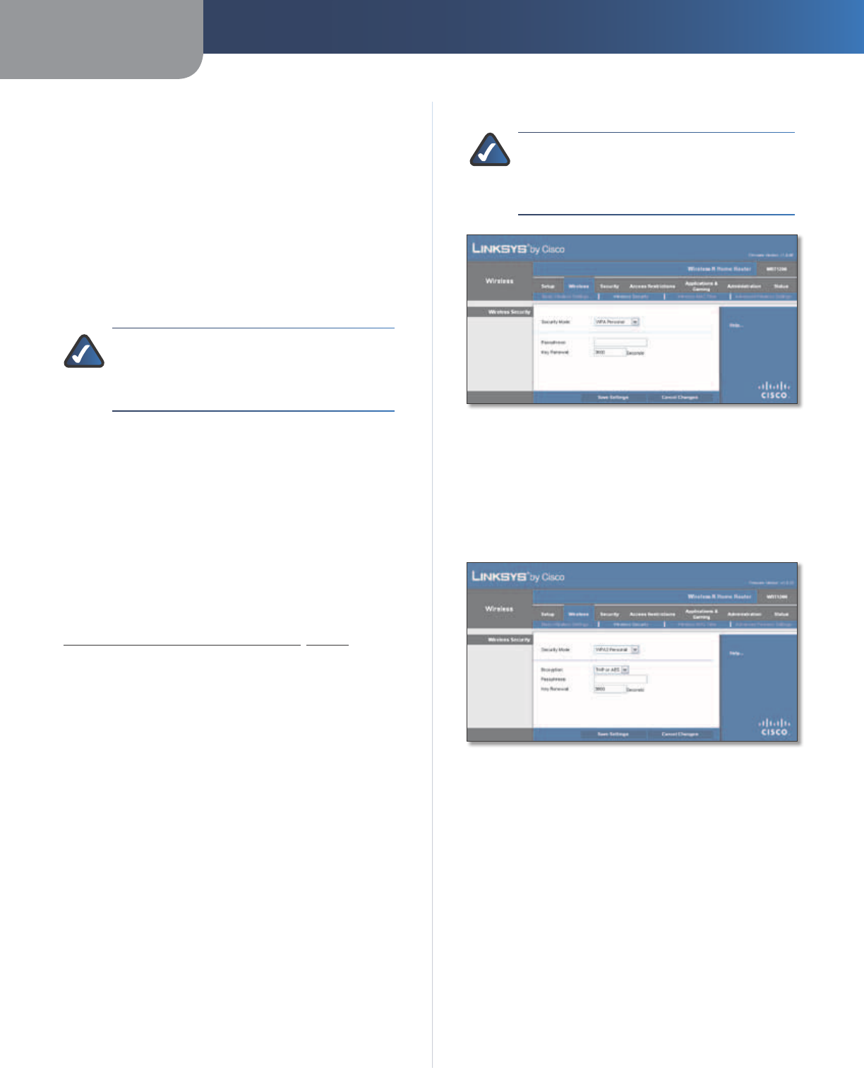
WPA2 Personal
Security Mode > WPA2 Personal
Encryption WPA2 supports two encryption methods,
TKIP and AES, with dynamic encryption keys. Select the
type of algorithm, AES or TKIP or AES. The default is TKIP
or AES.
Passphrase Enter a Passphrase of 8-63 characters.
Key Renewal Enter a Key Renewal period, which instructs
the Router how often it should change the encryption
keys. The default is 3600 seconds.
Chapter 3 Advanced Configuration
13
Wireless-N Home Router
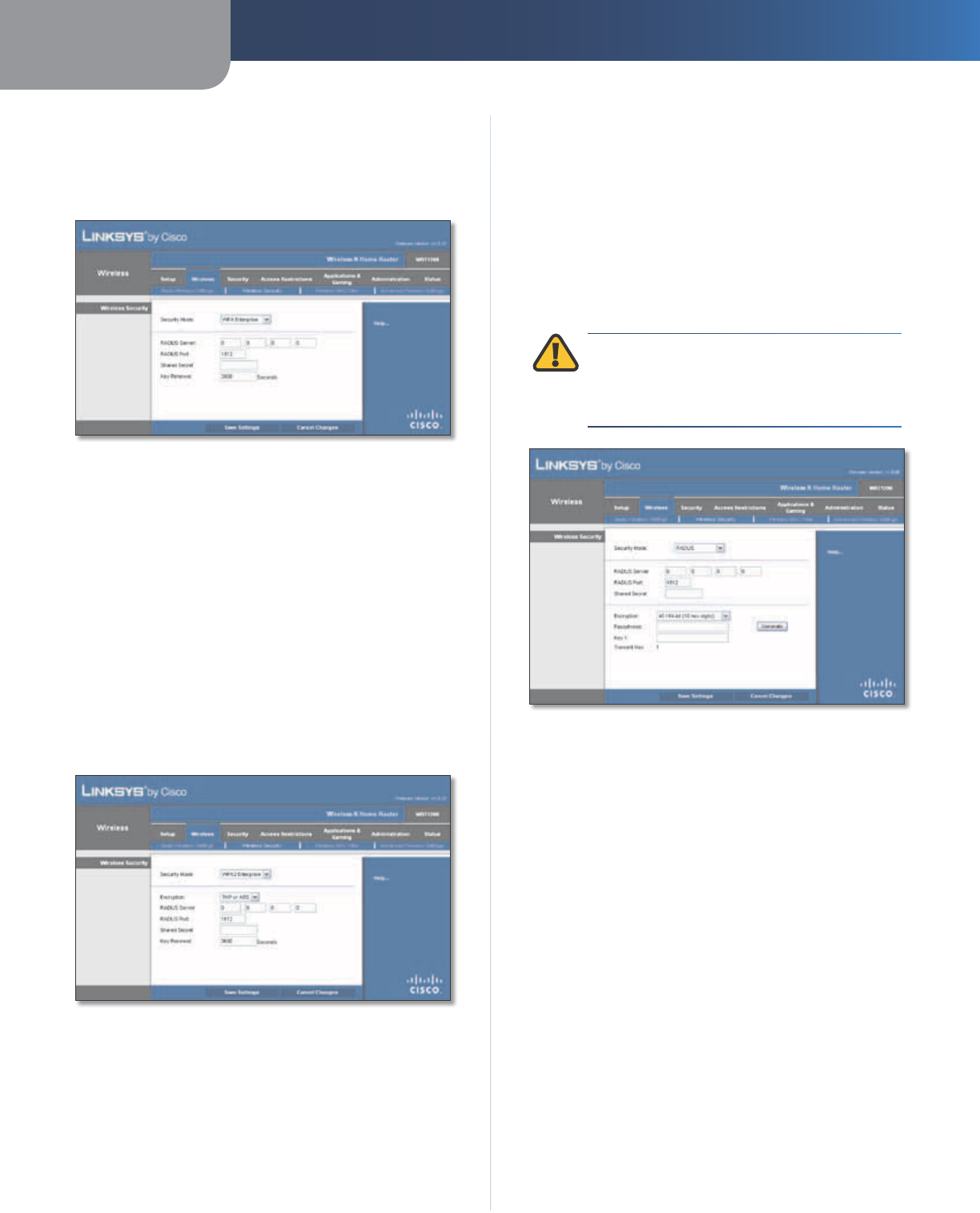
WPA Enterprise
This option features WPA used with a RADIUS server. (This
should only be used when a RADIUS server is connected
to the Router.)
Security Mode > WPA Enterprise
RADIUS Server Enter the IP address of the server.
RADIUS Port Enter the port number of the server. The
default is 1812.
Shared Secret Enter the key shared between the Router
and the server.
Key Renewal Enter a Key Renewal period, which instructs
the Router how often it should change the encryption
keys. The default is 3600 seconds.
WPA2 Enterprise
This option features WPA2 used with a RADIUS server. (This
should only be used when a RADIUS server is connected
to the Router.)
Security Mode > WPA2 Enterprise
Encryption WPA2 supports two encryption methods,
TKIP and AES, with dynamic encryption keys. Select the
type of algorithm, AES or TKIP or AES. The default is TKIP
or AES.
RADIUS Server Enter the IP address of the server.
RADIUS Port Enter the port number of the server. The
default is 1812.
Shared Secret Enter the key shared between the Router
and the server.
Key Renewal Enter a Key Renewal period, which instructs
the Router how often it should change the encryption
keys. The default is 3600 seconds.
RADIUS
This option features WEP used with a RADIUS server. (This
should only be used when a RADIUS server is connected
to the Router.)
IMPORTANT: If you are using WEP, then each
device in your wireless network MUST use the
same WEP encryption method and key, or else
the network will not function properly.
Security Mode > RADIUS
RADIUS Server Enter the IP address of the server.
RADIUS Port Enter the port number of the server. The
default is 1812.
Shared Secret Enter the key shared between the Router
and the server.
Encryption Select a level of WEP encryption,
40/64 bits (10 hex digits) or 104/128 bits (26 hex digits).
The default is 40/64 bits (10 hex digits).
Passphrase Enter a Passphrase to automatically generate
WEP keys. Then click Generate.
Key 1 If you did not enter a Passphrase, enter the WEP
key manually.
TX Key TX (Transmit) Key 1 is used.
Chapter 3 Advanced Configuration
14
Wireless-N Home Router
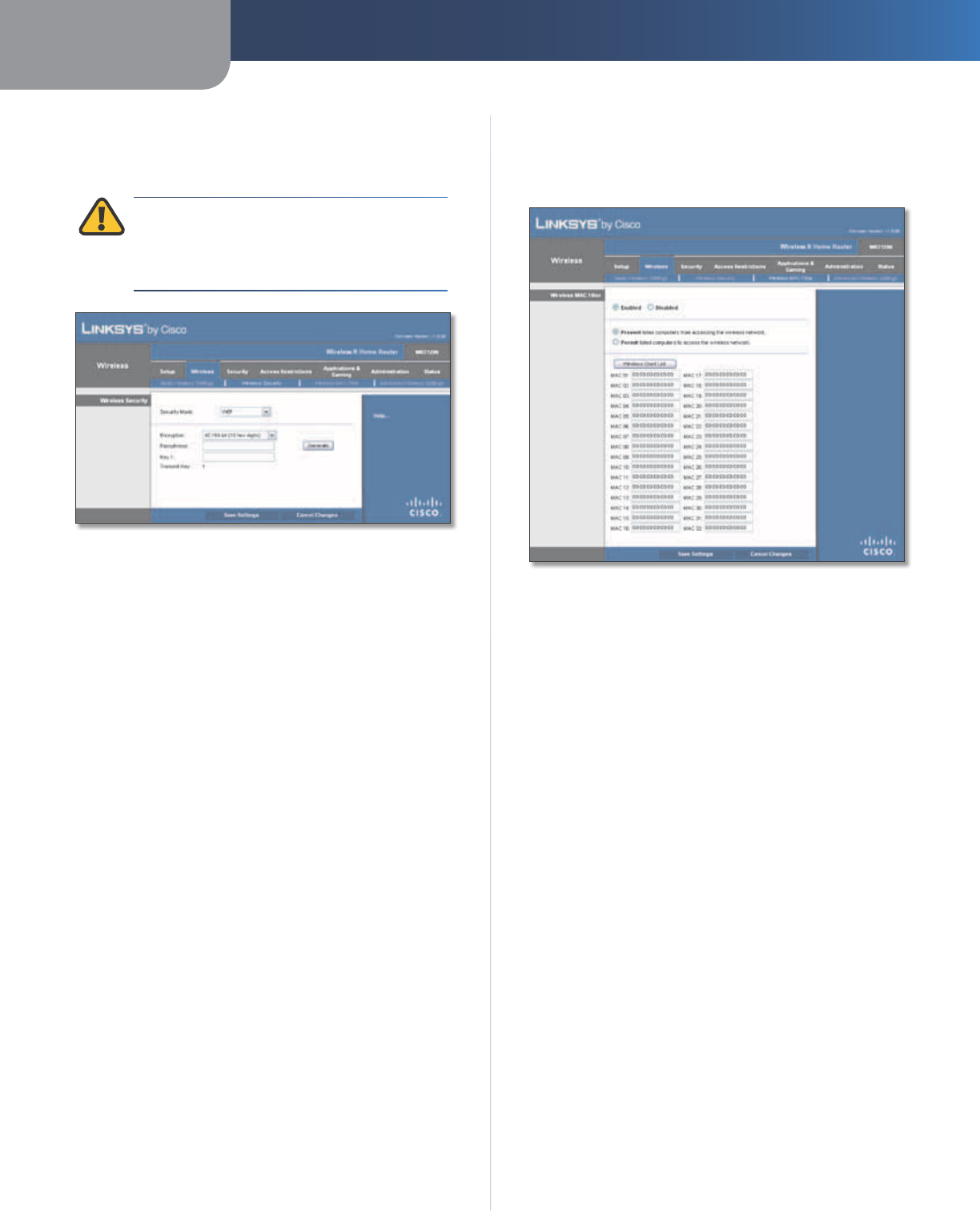
WEP
WEP is a basic encryption method, which is not as secure
as WPA.
IMPORTANT: If you are using WEP encryption,
then each device in your wireless network MUST
use the same WEP encryption method and key,
or else the network will not function properly.
Security Mode > WEP
Encryption Select a level of WEP encryption,
40/64 bits (10 hex digits) or 104/128 bits (26 hex digits).
The default is 40/64 bits (10 hex digits).
Passphrase Enter a Passphrase to automatically generate
WEP keys. Then click Generate.
Key 1 If you did not enter a Passphrase, enter the WEP
key manually.
TX Key TX (Transmit) Key 1 is used.
Click Save Settings to apply your changes, or click Cancel
Changes to clear your changes.
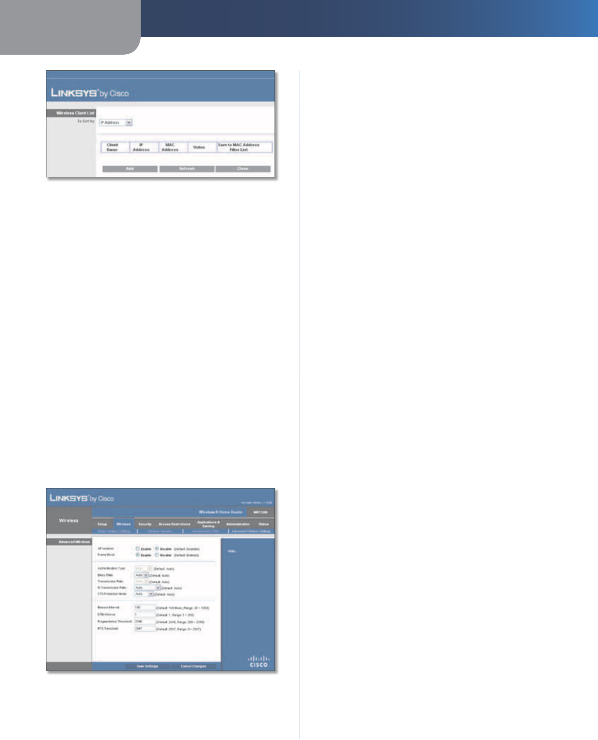
Wireless > Wireless MAC Filter
Wireless access can be filtered by using the MAC addresses of
the wireless devices transmitting within your network’s radius.
Wireless > Wireless MAC Filter
Wireless MAC Filter
Enabled/Disabled
To filter wireless users by MAC Address,
either permitting or blocking access, select Enabled. If you
do not wish to filter users by MAC Address, keep the default,
Disabled
.
Access Restriction
Prevent Select this option to block wireless access by
MAC Address. This button is selected by default.
Permit Select this option to allow wireless access by MAC
Address. This button is not selected by default.
MAC Address Filter List
Wireless Client List Click this button to open the Wireless
Client List screen.
Chapter 3 Advanced Configuration
15
Wireless-N Home Router
Wireless Client List
Wireless Client List
This screen shows computers and other devices on
the wireless network. The list can be sorted by Client
Name, IP Address, MAC Address, and Status.
Select Save to MAC Address Filter List for any device
you want to add to the MAC Address Filter List. Then
click Add.
To update the on-screen information, click Refresh.
To exit this screen and return to the Wireless MAC Filter
screen, click Close.
MAC 01-32 Enter the MAC addresses of the devices
whose wireless access you want to block or allow.
Click Save Settings to apply your changes, or click Cancel
Changes to clear your changes.
Wireless > Advanced Wireless Settings
This Advanced Wireless Settings screen is used to set up
the Router’s advanced wireless functions. These settings
should only be adjusted by an expert administrator as
incorrect settings can reduce wireless performance.
Wireless > Advanced Wireless Settings
Advanced Wireless
AP Isolation This option isolates all wireless clients and
wireless devices on your network from each other. Wireless
devices will be able to communicate with the Router but
not with each other. To use this option, select Enable. AP
Isolation is disabled by default.
Frame Burst This option should provide your network
with greater performance, depending on the manufacturer
of your wireless products. To use this option, keep the
default, Enable. To disable this option, select Disable.
Authentication Type The Authentication Type setting
is available if the Security Mode is RADIUS or WEP. The
default is set to Auto, which allows either Open System
or Shared Key authentication to be used. With Open
System authentication, the sender and the recipient do
NOT use a WEP key for authentication. With Shared Key
authentication, the sender and recipient use a WEP key for
authentication. Select Shared Key to only use Shared Key
authentication.
Basic Rate The Basic Rate setting is not actually one rate
of transmission but a series of rates at which the Router
can transmit. (The Basic Rate is not the actual rate of
data transmission. If you want to specify the Router’s rate
of data transmission, configure the Transmission Rate
setting.) The Router will advertise its Basic Rate to the other
wireless devices in your network, so they know which
rates will be used. The Router will also advertise that it will
automatically select the best rate for transmission. The
default setting is Auto, when the Router can transmit at
all standard wireless rates (1-2 Mbps, 5.5 Mbps, 11 Mbps,
18 Mbps, and 24Mbps). Select 1-2Mbps for use with older
wireless technology. Select All, when the Router can
transmit at all wireless rates.
Transmission Rate The Transmission setting is available
if the Network Mode is BG-Mixed, Wireless-G Only, or
Wireless-B Only. The rate of data transmission should be set
depending on the speed of your wireless network. Select
from a range of transmission speeds, or keep the default,
Auto, to have the Router automatically use the fastest
possible data rate and enable the Auto-Fallback feature.
Auto-Fallback will negotiate the best possible connection
speed between the Router and a wireless client.
N Transmission Rate The N Transmission setting is
available if the Network Mode is Mixed or Wireless-N Only.
The rate of data transmission should be set depending
on the speed of your Wireless-N networking. Select from
a range of transmission speeds, or keep the default,
Auto, to have the Router automatically use the fastest
possible data rate and enable the Auto-Fallback feature.
Auto-Fallback will negotiate the best possible connection
speed between the Router and a wireless client.
CTS Protection Mode The Router automatically uses CTS
(Clear-To-Send) Protection Mode when your Wireless-N and
Chapter 3 Advanced Configuration
16
Wireless-N Home Router
Wireless-G devices are experiencing severe problems and
are not able to transmit to the Router in an environment
with heavy 802.11b traffic. This option boosts the Router’s
ability to catch all Wireless-N and Wireless-G transmissions
but severely decreases performance. To use this option,
keep the default, Auto. To disable this option, select
Disabled.
Beacon Interval Enter a value between 1 and 65,535
milliseconds. The Beacon Interval value indicates the
frequency interval of the beacon. A beacon is a packet
broadcast by the Router to synchronize the wireless
network. The default is 100 milliseconds.
DTIM Interval This value, between 1 and 255, indicates
the interval of the Delivery Traffic Indication Message
(DTIM). A DTIM field is a countdown field informing
clients of the next window for listening to broadcast
and multicast messages. When the Router has buffered
broadcast or multicast messages for associated clients, it
sends the next DTIM with a DTIM Interval value. Its clients
hear the beacons and awaken to receive the broadcast
and multicast messages. The default value is 1.
Fragmentation Threshold This value specifies the
maximum size for a packet before data is fragmented
into multiple packets. If you experience a high packet
error rate, you may slightly increase the Fragmentation
Threshold. Setting the Fragmentation Threshold too low
may result in poor network performance. Only minor
reduction of the default value is recommended. In most
cases, it should remain at its default value of 2346.
RTS Threshold Should you encounter inconsistent data
flow, only minor reduction of the default value, 2347, is
recommended. If a network packet is smaller than the
preset RTS threshold size, the RTS/CTS mechanism will
not be enabled. The Router sends Request to Send (RTS)
frames to a particular receiving station and negotiates
the sending of a data frame. After receiving an RTS, the
wireless station responds with a Clear to Send (CTS) frame
to acknowledge the right to begin transmission. The RTS
Threshold value should remain at its default value of
2347.
Click Save Settings to apply your changes, or click Cancel
Changes to clear your changes.
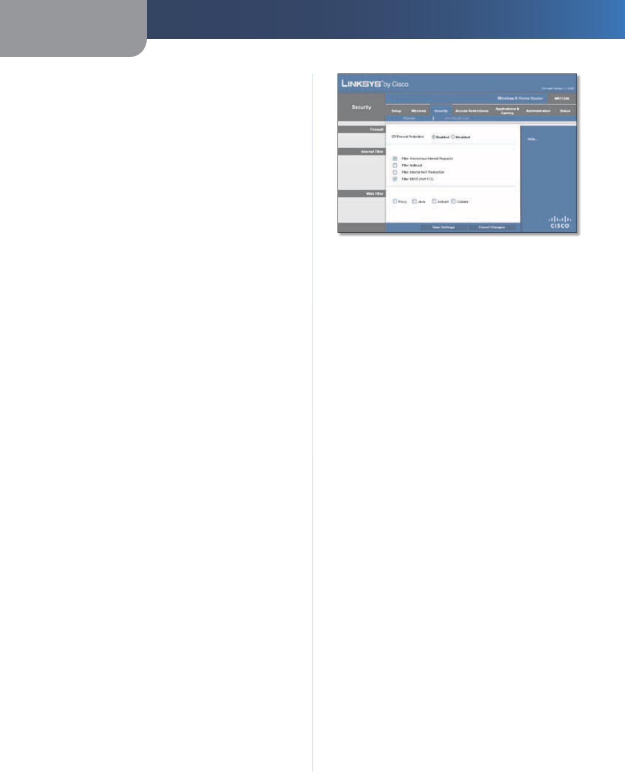
Security > Firewall
The Firewall screen is used to configure a firewall that can
filter out various types of unwanted traffic on the Router’s
local network.
Security > Firewall
Firewall
SPI Firewall Protection To use firewall protection,
keep the default selection, Enabled. To turn off firewall
protection, select Disabled.
Internet Filter
For the following options, select the option to enable it, or
deselect the option to disable it.
Filter Anonymous Internet Requests This feature makes
it more difficult for outside users to work their way into
your network. This feature is enabled by default. Deselect
this option to allow anonymous Internet requests
.
Filter Multicast Multicasting allows for multiple
transmissions to specific recipients at the same time. If
multicasting is permitted, then the Router will allow IP
multicast packets to be forwarded to the appropriate
computers. Select this option to filter multicasting. This
option is disabled by default.
Filter Internet NAT Redirection This feature uses port
forwarding to block access to local servers from local
networked computers. Select this option to filter Internet
NAT redirection. This option is disabled by default.
Filter IDENT (Port 113) This feature keeps port 113 from
being scanned by devices outside of your local network.
This feature is enabled by default. Deselect this option to
disable it.
Web Filter
For the following options, select the option to enable it, or
deselect the option to disable it.
Proxy Use of WAN proxy servers may compromise the
Gateway’s security. Denying Proxy will disable access to
any WAN proxy servers. Select this option to enable proxy
filtering. This option is disabled by default.
Java Java is a programming language for websites. If you
deny Java, you run the risk of not having access to Internet
sites created using this programming language. Select
Chapter 3 Advanced Configuration
17
Wireless-N Home Router
this option to enable Java filtering. This option is disabled
by default.
ActiveX ActiveX is a programming language for websites.
If you deny ActiveX, you run the risk of not having access to
Internet sites created using this programming language.
Select this option to enable ActiveX filtering. This option
is disabled by default.
Cookies A cookie is data stored on your computer and
used by Internet sites when you interact with them. Select
this option to filter cookies. This option is disabled by
default.
Click Save Settings to apply your changes, or click Cancel
Changes to clear your changes.
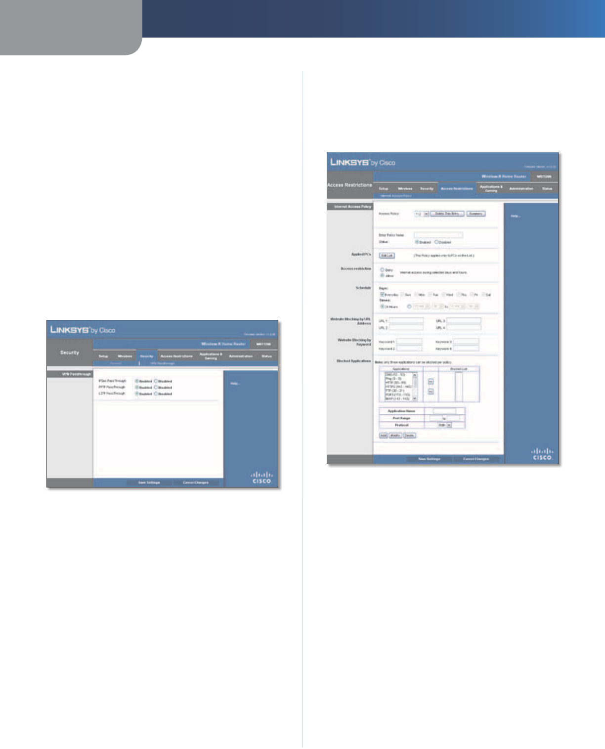
Security > VPN Passthrough
The VPN Passthrough screen allows you to enable VPN
tunnels using IPSec, PPTP, or L2TP protocols to pass through
the Router’s firewall.
Security > VPN Passthrough
VPN Passthrough
IPSec Passthrough Internet Protocol Security (IPSec) is
a suite of protocols used to implement secure exchange
of packets at the IP layer. To allow IPSec tunnels to pass
through the Router, keep the default, Enabled.
PPTP Passthrough Point-to-Point Tunneling Protocol
(PPTP) allows the Point-to-Point Protocol (PPP) to be
tunneled through an IP network. To allow PPTP tunnels to
pass through the Router, keep the default, Enabled.
L2TP Passthrough Layer 2 Tunneling Protocol is the
method used to enable Point-to-Point sessions via the
Internet on the Layer 2 level. To allow L2TP tunnels to pass
through the Router, keep the default, Enabled.
Click Save Settings to apply your changes, or click Cancel
Changes to clear your changes.
Access Restrictions > Internet Access
The Internet Access screen allows you to block or allow
specific kinds of Internet usage and traffic, such as Internet
access, designated services, and websites during specific
days and times.
Access Restrictions > Internet Access
Internet Access Policy
Access Policy Access can be managed by a policy. Use
the settings on this screen to establish an access policy
(after Save Settings is clicked). Selecting a policy from
the drop-down menu will display that policy’s settings. To
delete a policy, select that policy’s number and click Delete
This Entry. To view all the policies, click Summary.
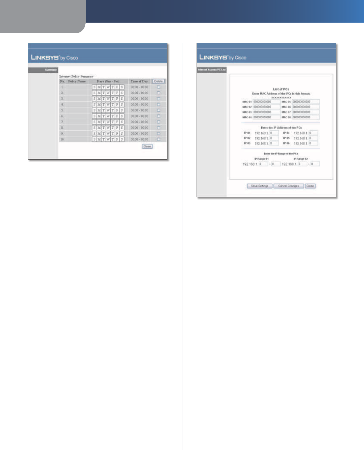
Summary
The policies are listed with the following information: No.,
Policy Name, Days, and Time of Day. To delete a policy,
select the policy’s Delete option, and then click Delete.
To return to the Internet Access Policy screen, click Close.
Chapter 3 Advanced Configuration
18
Wireless-N Home Router
Summary
Status Policies are disabled by default. To enable a policy,
select the policy number from the drop-down menu, and
select Enabled.
To create a policy, follow steps 1-11. Repeat these steps to
create additional policies, one at a time.
1. Select a number from the Access Policy drop-down
menu.
2. Enter a Policy Name in the field provided.
3. To enable this policy, select Enabled.
4. Click Edit List to select which computers will be
affected by the policy. The Internet Access PC List screen
appears. You can select a computer by MAC address or
IP address. You can also enter a range of IP addresses
if you want this policy to affect a group of computers.
After making your changes, click Save Settings to
apply your changes, or click Cancel Changes to clear
your changes. Then click Close.
Internet Access PC List
5. Select the appropriate option, Deny or Allow,
depending on whether you want to block or allow
Internet access for the computers you listed on the
Internet Access PC List screen.
6. Decide which days and what times you want this policy
to be enforced. Select the individual days during which
the policy will be in effect, or select Everyday. Then
enter a range of hours and minutes during which the
policy will be in effect, or select 24 Hours.
7. You can block websites with specific URL addresses.
Enter each URL in a separate Website Blocking by URL
Address field.
8. You can also block websites using specific keywords.
Enter each keyword in a separate Website Blocking by
Keyword field.
9. You can filter access to various services accessed
over the Internet, such as FTP or telnet. (You
can block up to three applications per policy.)
From the Applications list, select the application you
want to block. Then click the >> button to move it to
the Blocked List. To remove an application from the
Blocked List, select it and click the << button.
10. If the application you want to block is not listed or you
want to edit a service’s settings, enter the application’s
name in the Application Name field. Enter its range
in the Port Range fields. Select its protocol from the
Protocol drop-down menu. Then click Add.
To modify a service, select it from the Application list.
Change its name, port range, and/or protocol setting.
Then click Modify.
Chapter 3 Advanced Configuration
19
Wireless-N Home Router
To delete a service, select it from the Application list.
Then click Delete.
11. Click Save Settings to save the policy’s settings, or
click Cancel Changes to clear the changes.
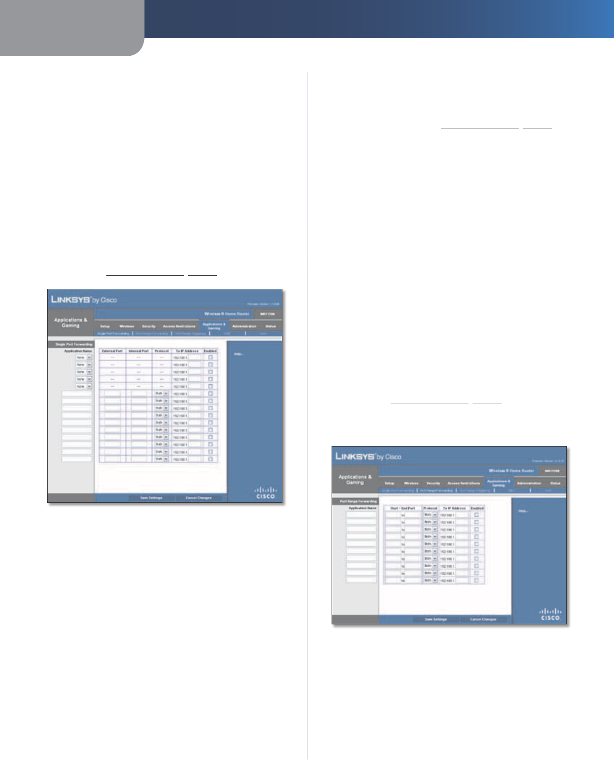
Applications and Gaming > Single Port
Forwarding
The Single Port Forwarding screen allows you to customize
port services for common applications on this screen.
When users send these types of requests to your network via
the Internet, the Router will forward those requests to the
appropriate servers (computers). Before using forwarding,
you should assign static IP addresses to the designated
servers (use the DHCP Reservation feature on the Basic Setup
screen; refer to DHCP Reservation, page 7).
Applications and Gaming > Single Port Forwarding
Single Port Forwarding
Common applications are available for the first five
entries. Select the appropriate application. Then enter the
IP address of the server that should receive these requests.
Select Enabled to activate this entry.
For additional applications, complete the following fields:
Application Name Enter the name you wish to give the
application. Each name can be up to 12 characters.
External Port Enter the external port number used by
the server or Internet application. Check with the Internet
application documentation for more information.
Internal Port Enter the internal port number used by
the server or Internet application. Check with the Internet
application documentation for more information.
Protocol Select the protocol(s) used for this application,
TCP, UDP, or Both.
To IP Address For each application, enter the IP address
of the computer that should receive the requests. If you
assigned a static IP address to the computer, then you
can look up its IP address; click DHCP Reservation on the
Basic Setup screen (r
efer to DHCP Reservation, page 7).
Enabled For each application, select Enabled to enable
port forwarding.
Click Save Settings to apply your changes, or click Cancel
Changes to clear your changes.
Applications and Gaming > Port Range
Forwarding
The Port Range Forwarding screen allows you to set up
public services on your network, such as web servers,
ftp servers, e-mail servers, or other specialized Internet
applications. (Specialized Internet applications are any
applications that use Internet access to perform functions
such as videoconferencing or online gaming. Some Internet
applications may not require any forwarding.)
When users send these types of requests to your network via
the Internet, the Router will forward those requests to the
appropriate servers (computers). Before using forwarding,
you should assign static IP addresses to the designated
servers (use the DHCP Reservation feature on the Basic Setup
screen; refer to DHCP Reservation, page 7).
If you need to forward all ports to one computer, click the
DMZ tab.
Applications and Gaming > Port Range Forwarding
Port Range Forwarding
To forward a port, enter the information on each line for
the criteria required.
Application Name In this field, enter the name you
wish to give the application. Each name can be up to 12
characters.
Chapter 3 Advanced Configuration
20
Wireless-N Home Router
Start~End Port Enter the number or range of port(s)
used by the server or Internet applications. Check
with the Internet application documentation for more
information.
Protocol Select the protocol(s) used for this application,
TCP, UDP, or Both.
To IP Address For each application, enter the IP address
of the computer that should receive the requests. If you
assigned a static IP address to the computer, then you
can look up its IP address; click DHCP Reservation on the
Basic Setup screen (r
efer to DHCP Reservation, page 7).
Enabled Select Enabled to enable port forwarding for
the applications you have defined.
Click Save Settings to apply your changes, or click Cancel
Changes to clear your changes.
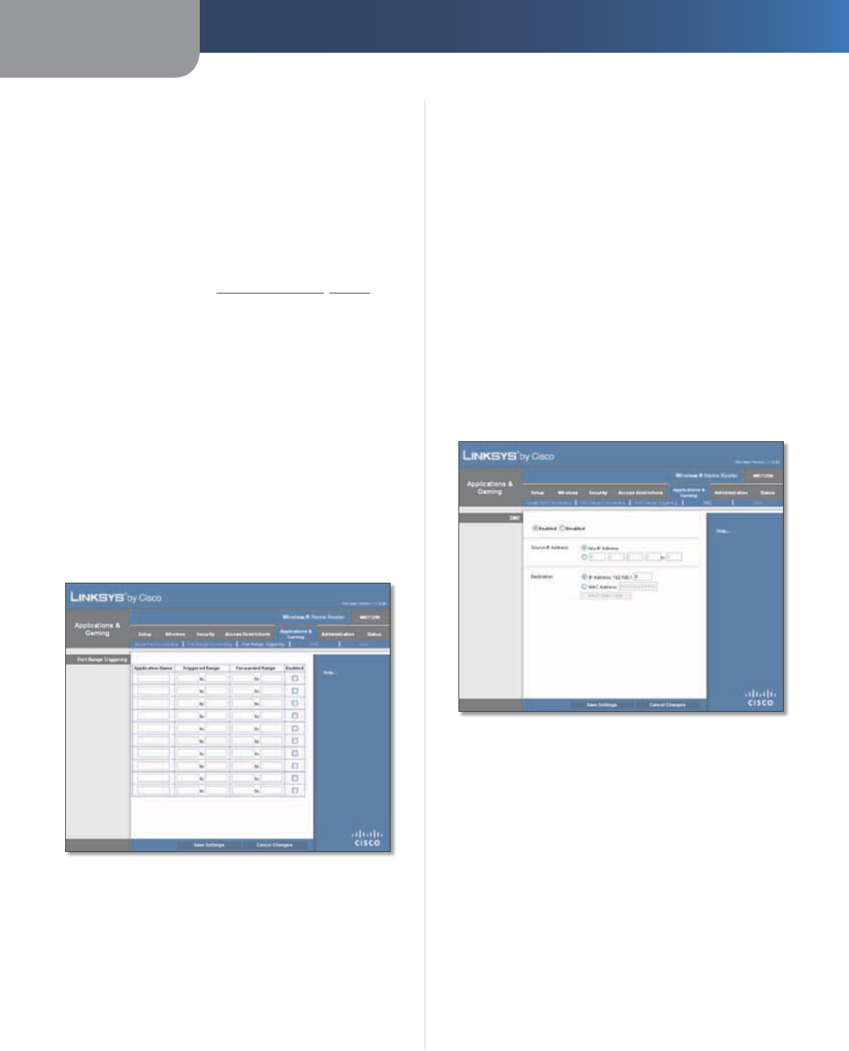
Applications & Gaming > Port Range
Triggering
The Port Range Triggering screen allows the Router to
watch outgoing data for specific port numbers. The IP
address of the computer that sends the matching data is
remembered by the Router, so that when the requested
data returns through the Router, the data is pulled back
to the proper computer by way of IP address and port
mapping rules.
Applications and Gaming > Port Range Triggering
Port Range Triggering
Application Name Enter the application name of the
trigger.
Triggered Range For each application, enter the starting
and ending port numbers of the triggered port number
range. Check with the Internet application documentation
for the port number(s) needed.
Forwarded Range For each application, enter the starting
and ending port numbers of the forwarded port number
range. Check with the Internet application documentation
for the port number(s) needed.
Enabled Select Enabled to enable port triggering for the
applications you have defined.
Click Save Settings to apply your changes, or click Cancel
Changes to clear your changes.
Applications and Gaming > DMZ
The DMZ feature allows one network computer to be
exposed to the Internet for use of a special-purpose
service such as Internet gaming or videoconferencing.
DMZ hosting forwards all the ports at the same time to
one computer. The Port Range Forwarding feature is more
secure because it only opens the ports you want to have
opened, while DMZ hosting opens all the ports of one
computer, exposing the computer to the Internet.
Applications and Gaming > DMZ
DMZ
Any computer whose port is being forwarded must have
its DHCP client function disabled and should have a new
static IP address assigned to it because its IP address may
change when using the DHCP function.
Enabled/Disabled To disable DMZ hosting, select
Disabled. To expose one computer, select Enabled. Then
configure the following settings:
Source IP Address If you want any IP address to be the
source, select Any IP Address. If you want to specify an IP
address or range of IP addresses as the designated source,
select and complete the IP address range fields.
Destination If you want to specify the DMZ host by IP
address, select IP Address and enter the IP address in
the field provided. If you want to specify the DMZ host
Chapter 3 Advanced Configuration
21
Wireless-N Home Router
by MAC address, select MAC Address and enter the MAC
address in the field provided. To retrieve this information,
click DHCP Client Table.
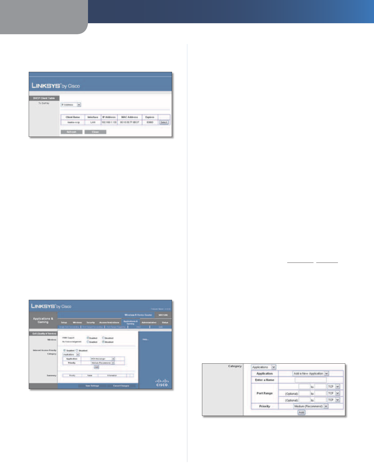
DMZ > DHCP Client Table
DHCP Client Table
The DHCP Client Table lists computers and other
devices that have been assigned IP addresses by the
Router. The list can be sorted by Client Name, Interface,
IP Address, MAC Address, and Expires time (how
much time is left for the current IP address). To select
a DHCP client, click Select. To update the on-screen
information, click Refresh. To exit this screen and
return to the DMZ screen, click Close.
Click Save Settings to apply your changes, or click Cancel
Changes to clear your changes.
Applications and Gaming > QoS
Quality of Service (QoS) ensures better service to
high-priority types of network traffic, which may
involve demanding, real-time applications, such as
videoconferencing.
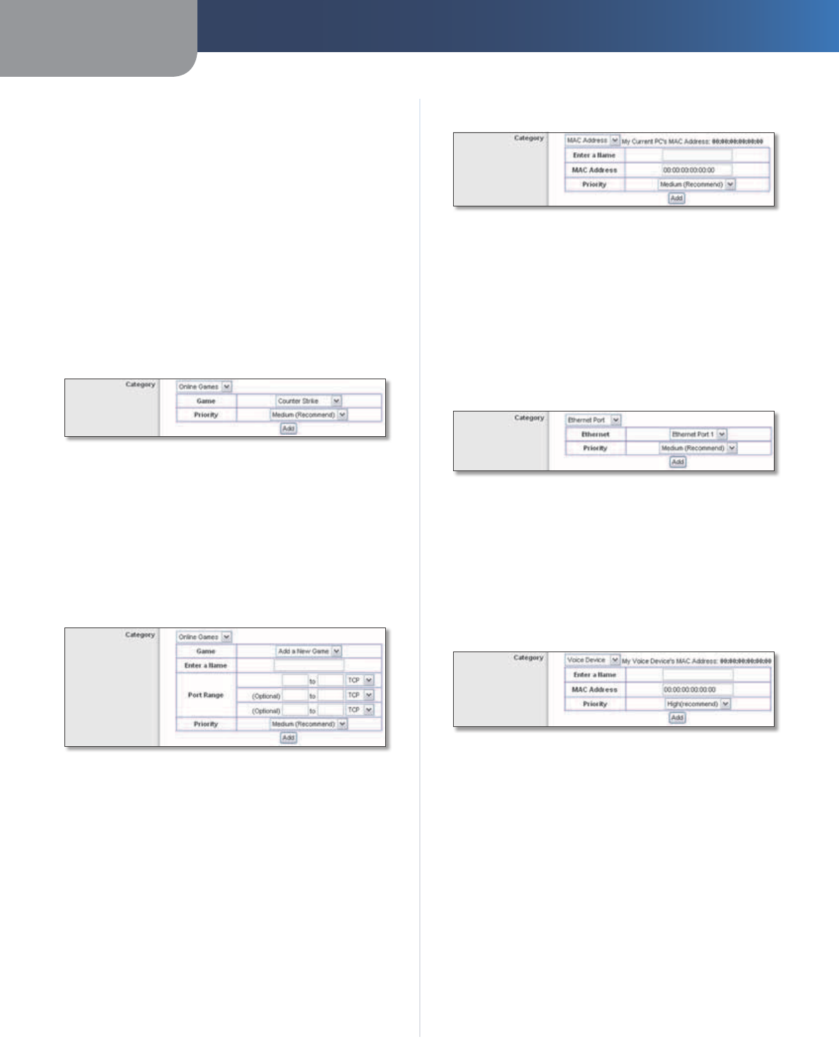
Applications and Gaming > QoS
QoS (Quality of Service)
Wireless
You can configure the support and No Acknowledgement
settings in this section.
WMM Support If you have other devices that support
Wi-Fi Multimedia (WMM) on your network, keep the
default, Enabled. Otherwise, select Disabled.
No Acknowledgement If you want to disable the Router’s
Acknowledgement feature, so the Router will not re-send
data if an error occurs, then select Enabled. Otherwise,
keep the default, Disabled.
Internet Access Priority
In this section, you can set the bandwidth priority for a
variety of applications and devices. There are four levels
priority: High, Medium, Normal, or Low. When you set
priority, do not set all applications to High, because this will
defeat the purpose of allocating the available bandwidth.
If you want to select below normal bandwidth, select Low.
Depending on the application, a few attempts may be
needed to set the appropriate bandwidth priority.
Enabled/Disabled To use the QoS policies you have set,
keep the default, Enabled. Otherwise, select Disabled.
Category
Select one of the following categories: Applications,
Online Games, MAC Address, Ethernet Port, or Voice
Device. Proceed to the instructions for your selection.
Summary
This lists the QoS entries you have created for your
applications and devices. Refer to Summary, page 22 for
more information.
Applications
Application Select the appropriate application. If you
select Add a New Application, follow the Add a New
Application instructions.
Priority Select the appropriate priority: High, Medium
(Recommend), Normal, or Low.
Click Add to save your changes. Your new entry appears in
the Summary list.
Add a New Application
QoS > Add a New Application
Enter a Name Enter any name to indicate the name of
the entry.
Chapter 3 Advanced Configuration
22
Wireless-N Home Router
Port Range Enter the port range that the application will
be using. For example, if you want to allocate bandwidth
for FTP, you can enter 21-21. If you need services for an
application that uses from 1000 to 1250, you enter 1000-
1250 as your settings. You can have up to three ranges
to define for this bandwidth allocation. Port numbers
can range from 1 to 65535. Check your application’s
documentation for details on the service ports used.
Select the protocol TCP or UDP, or select Both.
Priority Select the appropriate priority: High, Medium
(Recommend), Normal, or Low.
Click Add to save your changes. Your new entry appears in
the Summary list.
Online Games
QoS > Online Games
Game Select the appropriate game. If you select Add a
New Game, follow the Add a New Game instructions.
Priority Select the appropriate priority: High, Medium
(Recommend), Normal, or Low.
Click Add to save your changes. Your new entry appears in
the Summary list.
Add a New Game
QoS > Add a New Game
Enter a Name Enter any name to indicate the name of
the entry.
Port Range Enter the port range that the game will be
using. You can have up to three ranges to define for this
bandwidth allocation. Port numbers can range from 1 to
65535. Check your application’s documentation for details
on the service ports used.
Select the protocol TCP or UDP, or select Both.
Priority Select the appropriate priority: High, Medium
(Recommend), Normal, or Low.
Click Add to save your changes. Your new entry appears in
the Summary list.
MAC Address
QoS > MAC Address
Enter a Name Enter a name for your device.
MAC Address Enter the MAC address of your device.
Priority Select the appropriate priority: High, Medium
(Recommend), Normal, or Low.
Click Add to save your changes. Your new entry appears in
the Summary list.
Ethernet Port
QoS > Ethernet Port
Ethernet Select the appropriate Ethernet port.
Priority Select the appropriate priority: High, Medium
(Recommend), Normal, or Low.
Click Add to save your changes. Your new entry appears in
the Summary list.
Voice Device
QoS > Voice Device
My Voice Device’s MAC Address The MAC address of
your voice device is automatically displayed.
Enter a Name Enter a name for your voice device.
MAC Address Enter the MAC address of your voice
device.
Priority Select the appropriate priority: High
(Recommend), Medium, Normal, or Low.
Click Add to save your changes. Your new entry appears in
the Summary list.
Summary
This lists the QoS entries you have created for your
applications and devices.
Chapter 3 Advanced Configuration
23
Wireless-N Home Router
Priority This column displays the bandwidth priority of
High, Medium, Normal, or Low.
Name This column displays the application, device, or
port name.
Information This column displays the port range or
MAC address entered for your entry. If a pre-configured
application or game was selected, there will be no valid
entry shown in this section.
Remove Click this button to remove an entry.
Edit Click this button to make changes.
Click Save Settings to apply your changes, or click Cancel
Changes to clear your changes.
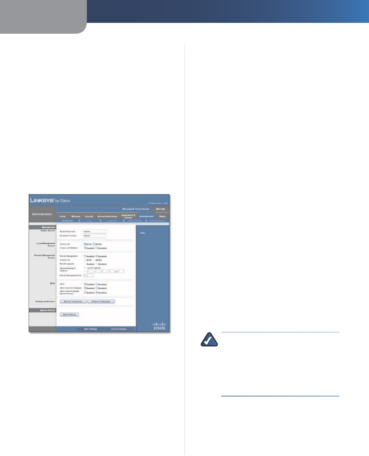
Administration > Management
The Administration > Management screen allows the
network’s administrator to manage specific Router
functions for access and security.
Administration > Management
Management
Router Access
To ensure the Router’s security, you will be asked for your
password when you access the Router’s browser-based
utility. The default is admin.
Router Password Enter a new password for the Router.
Re-enter to confirm Enter the password again to
confirm.
Local Management Access
Access via HTTP (HyperText Transport Protocol) is the
communications protocol used to connect to servers on
the World Wide Web. HTTPS uses SSL (Secured Socket
Layer) to encrypt data transmitted for higher security.
Select HTTP or HTTPS. HTTP is the default.
Access via Wireless If you are using the Router in a public
domain where you are giving wireless access to your
guests, you can disable wireless access to the Router’s
browser-based utility. You will only be able to access the
utility via a wired connection if you disable the setting.
Keep the default, Enabled, to allow wireless access to the
utility, or select Disabled to block wireless access to the
utility.
Remote Management Access
Remote Management To permit remote access of the
Router, from outside the local network, select Enabled.
Otherwise, keep the default, Disabled.
Access via HTTP (HyperText Transport Protocol) is the
communications protocol used to connect to servers on
the World Wide Web. HTTPS uses SSL (Secured Socket
Layer) to encrypt data transmitted for higher security.
Select HTTP or HTTPS. HTTP is the default.
Remote Upgrade If you want to be able to upgrade the
Router remotely, from outside the local network, select
Enabled. (You must have the Remote Management
feature enabled as well.) Otherwise, keep the default,
Disabled.
Allowed Remote IP Address If you want to be able to
access the Router from any external IP address, select Any
IP Address. If you want to specify an external IP address or
range of IP addresses, then select the second option and
complete the fields provided.
Remote Management Port Enter the port number that
will be open to outside access.
NOTE: When you are in a remote location
and wish to manage the Router, enter
http://xxx.xxx.xxx.xxx:yyyy or
https://xxx.xxx.xxx.xxx:yyyy, depending
on whether you use HTTP or HTTPS. Enter the
Router’s specific Internet IP address in place
of xxx.xxx.xxx.xxx, and enter the Remote
Management Port number in place of yyyy.
UPnP
Universal Plug and Play (UPnP) allows the appropriate
Windows operating system to automatically configure the
Router for various Internet applications, such as gaming
and videoconferencing.
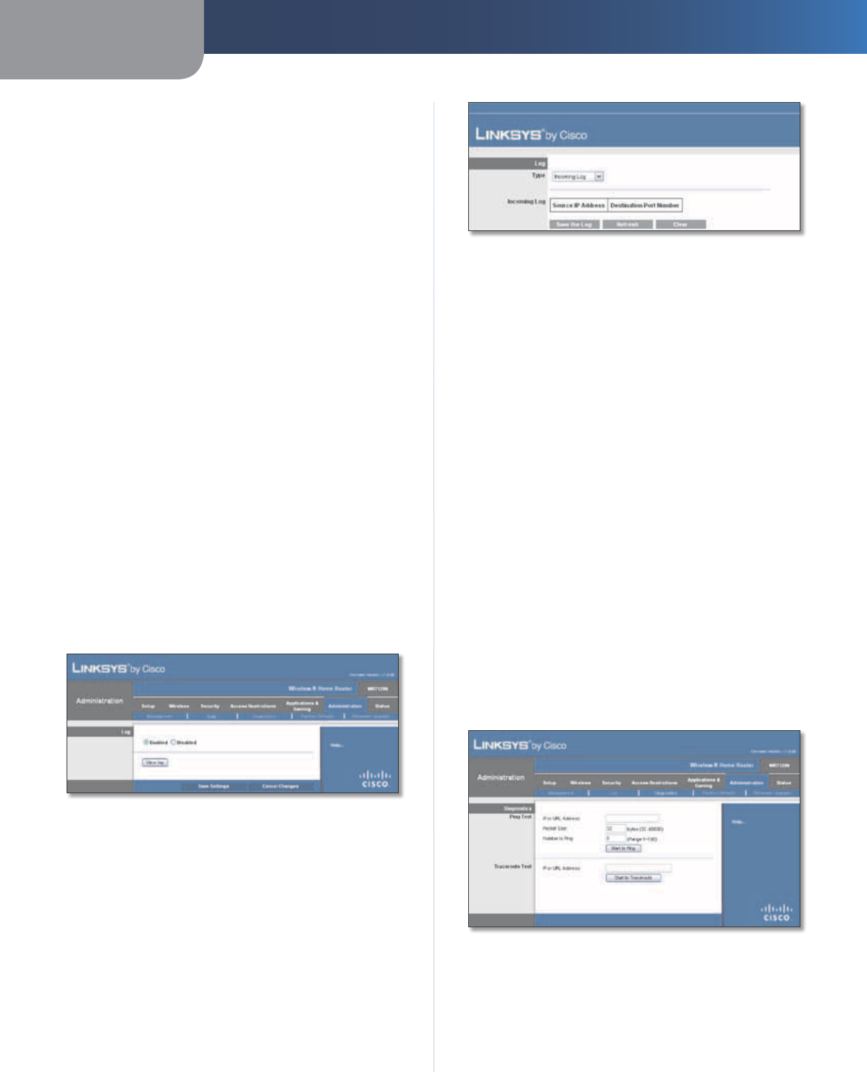
Chapter 3 Advanced Configuration
24
Wireless-N Home Router
UPnP To use UPnP, keep the default, Enabled. Otherwise,
select Disabled.
Allow Users to Configure Keep the default, Enabled,
if you want to be able to make manual changes to the
Router while using the UPnP feature. Otherwise, select
Disabled.
Allow Users to Disable Internet Access Select Enabled,
if you want to be able to prohibit any and all Internet
connections. Otherwise, keep the default, Disabled.
Backup and Restore
Backup Configuration To back up the Router’s
configuration settings, click this button and follow the
on-screen instructions.
Restore Configuration To restore the Router’s
configuration settings, click this button and follow the
on-screen instructions. (You must have previously backed
up the Router’s configuration settings.)
System Reboot
Start to Reboot If you need to restart the Router, click
this button.
Click Save Settings to apply your changes, or click Cancel
Changes to clear your changes.
Administration > Log
The Router can keep logs of all traffic for your Internet
connection.
Administration > Log
Log
Enabled/Disabled To disable the Log function, select
Disabled. To monitor traffic between the network and the
Internet, keep the default, Enabled. With logging enabled,
you can choose to view temporary logs.
View Log To view the logs, click View Log.
Log > View Log
Log
•Type Select Incoming Log, Outgoing Log, Security
Log, or DHCP Client Log.
•<Type> Log The Incoming Log displays a temporary
log of the source IP addresses and destination
port numbers for the incoming Internet traffic. The
Outgoing Log displays a temporary log of the local IP
addresses, destination URLs/IP addresses, and service/
port numbers for the outgoing Internet traffic. The
Security log displays the login information for the
browser-based utility. The DHCP Client Log displays
the LAN DHCP server status information.
Click Save the Log to save this information to a file on
your computer’s hard drive. Click Refresh to update
the log. Click Clear to clear all the information that is
displayed.
Click Save Settings to apply your changes, or click Cancel
Changes to clear your changes.
Administration > Diagnostics
The diagnostic tests (Ping and Traceroute) allow you to
check the connections of your network devices, including
connection to the Internet.
Administration > Diagnostics
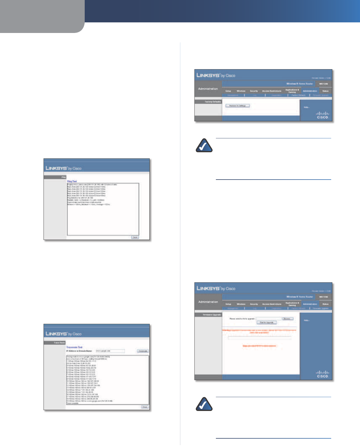
Chapter 3 Advanced Configuration
25
Wireless-N Home Router
Diagnostics
Ping Test
Ping checks the status of a connection.
IP or URL Address Enter the address of the computer
whose connection you wish to test.
Packet Size Enter the packet size you want to use. The
default is 32 bytes.
Number to Ping Enter the number of times you wish to
test the connection. The default is 5.
Start to Ping To run the test, click this button. The Ping
screen shows if the test is successful. Click Close to return
to the Diagnostics screen.
Diagnostics > Ping
Traceroute Test
Traceroute checks the performance of a connection.
IP or URL Address Enter the address of the computer
whose connection you wish to test.
Start to Traceroute To run the test, click this button. The
Traceroute screen shows if the test is successful. Click Close
to return to the Diagnostics screen.
Diagnostics > Traceroute
Administration > Factory Defaults
Restore the Router to its factory default settings.
Administration > Factory Defaults
NOTE: Do not restore the factory defaults unless
you are having difficulties with the Router and
have exhausted all other troubleshooting
measures. Once the Router is reset, you will have
to re-enter all of your configuration settings.
Factory Defaults
Restore All Settings To reset the Router’s settings to the
defaults, click this button and then follow the on-screen
instructions. Any custom settings you have saved will be
lost when the default settings are restored.
Administration > Firmware Upgrade
The Firmware Upgrade screen allows you to upgrade the
Router’s firmware. Do not upgrade the firmware unless
you are experiencing problems with the Router or the new
firmware has a feature you want to use.
Administration > Firmware Upgrade
NOTE: The Router may lose the settings you
have customized. Before you upgrade its
firmware, write down all of your custom settings.
After you upgrade its firmware, you may have to
re-enter all of your configuration settings.
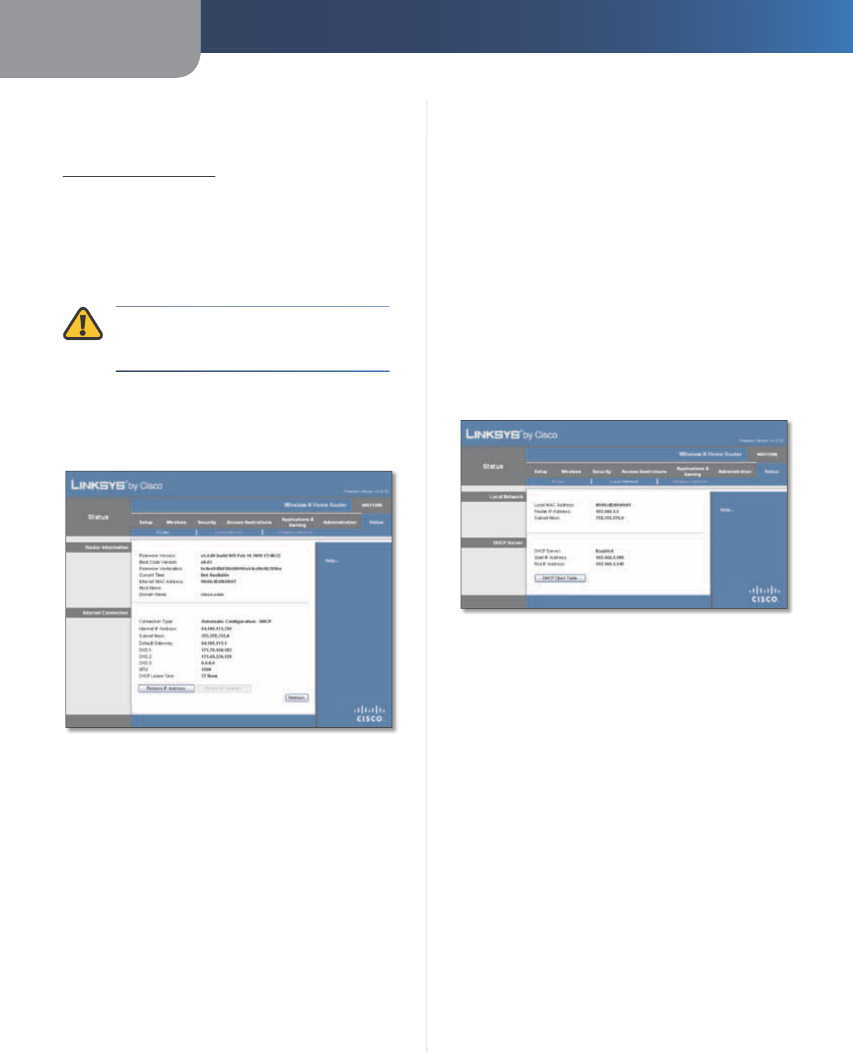
Chapter 3 Advanced Configuration
26
Wireless-N Home Router
Firmware Upgrade
Before upgrading the firmware, download the Router’s
firmware upgrade file from the Linksys website,
www.linksysbycisco.com.
Please select a file to upgrade To select the firmware
upgrade file, click Browse and follow the on-screen
instructions.
Start to Upgrade After you have selected the
appropriate file, click this button, and f
ollow the on-screen
instructions.
WARNING: The firmware upgrade must not
be interrupted; do not reboot or power off the
Router during the firmware upgrade.
Status > Router
The Router screen displays information about the Router
and its current settings.
Status > Router
Router Information
Firmware Version The version number of the Router’s
current firmware is displayed.
Boot Code Version The version number of the Router’s
boot code is displayed.
Firmware Verification The unique identifier of the
firmware is displayed.
Current Time The time set on the Router is displayed.
Internet MAC Address The Router’s MAC Address, as
seen by your ISP, is displayed.
Host Name The Host Name of the Router is displayed (if it
was entered on the Setup > Basic Setup screen).
Domain Name The Domain Name of the Router is
displayed (if it was entered on the Setup > Basic Setup
screen).
Internet Connection
This section shows the current network information
stored in the Router. The information varies depending on
the Internet connection type selected on the Setup > Basic
Setup screen.
Select Release IP Address or Renew IP Address as
appropriate to release or renew a DHCP lease.
Click Refresh to update the on-screen information.
Status > Local Network
The Local Network screen displays information about the
local, wired network.
Status > Local Network
Local Network
Local MAC Address The MAC address of the Router’s
local, wired interface is displayed.
Router IP Address The Router’s IP address, as it appears
on your local network, is displayed.
Subnet Mask The Subnet Mask of the Router is
displayed.
DHCP Server
DHCP Server The status of the Router’s DHCP server
function is displayed.
Start IP Address For the range of IP addresses that can
be used by devices on your local network, the starting IP
address is displayed.
End IP Address For the range of IP addresses that can
be used by devices on your local network, the ending IP
address is displayed.
DHCP Clients Table Click this button to view a list of
computers or other devices that are using the Router as
a DHCP server.
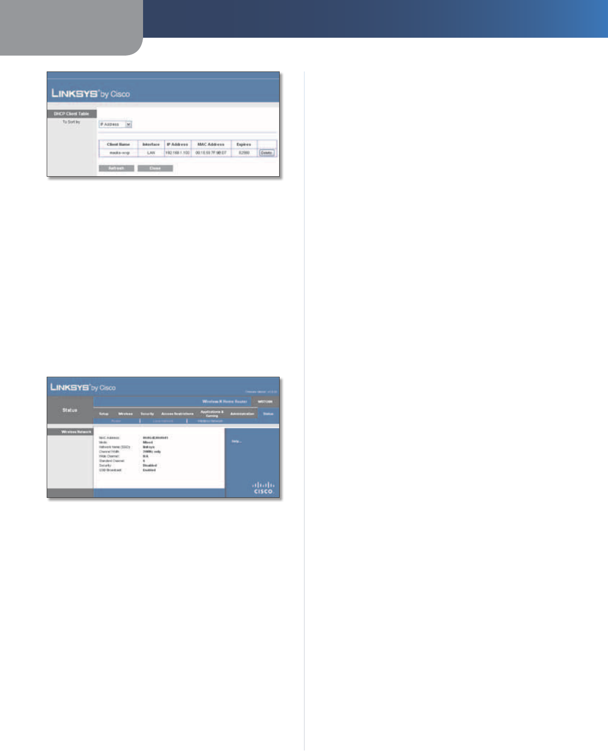
Chapter 3 Advanced Configuration
27
Wireless-N Home Router
DHCP Clients Table
DHCP Client Table
The DHCP Client Table lists computers and other
devices that have been assigned IP addresses by the
Router. The list can be sorted by IP Address, MAC
Address, Interface, and Client Name. To remove a
DHCP client, click Delete. To update the on-screen
information, click Refresh. To exit this screen and
return to the Local Network screen, click Close.
Status > Wireless Network
The Wireless Network screen displays information about
your wireless network.
Status > Wireless
Wireless Network
MAC Address The MAC address of the Router’s local,
wireless interface is displayed.
Mode The wireless mode used by the network is
displayed.
Network Name (SSID) The name of the wireless network,
which is also called the SSID, is displayed.
Channel Width The Channel Width setting (selected on
the Wireless > Basic Wireless Settings screen) is displayed.
Wide Channel The Wide Channel setting (selected on
the Wireless > Basic Wireless Settings screen) is displayed.
Standard Channel The Standard Channel setting
(selected on the Wireless > Basic Wireless Settings screen)
is displayed.
Security The wireless security method used by the Router
is displayed.
SSID Broadcast The status of the SSID Broadcast feature
is displayed.

Appendix A Troubleshooting
28
Wireless-N Home Router
Appendix A:
Troubleshooting
Your computer cannot connect to the Internet.
Follow these instructions until your computer can connect
to the Internet:
•Make sure that the Router is powered on. The Power
LED should be lit and not flashing.
•If the Power LED is flashing, then power off all of
your network devices, including the modem, Router,
and computers. Then power on each device in the
following order:
1. Cable or DSL modem
2. Router
3. Computer
•Check the cable connections. The computer should
be connected to one of the ports numbered 1-4 on
the Router, and the modem must be connected to the
Internet port on the Router.
The modem does not have an Ethernet port.
The modem is a dial-up modem for traditional dial-up
service. To use the Router, you need a cable/DSL modem
and high-speed Internet connection.
You cannot use the DSL service to connect manually to
the Internet.
After you have installed the Router, it will automatically
connect to your Internet Service Provider (ISP), so you no
longer need to connect manually.
The DSL telephone line does not fit into the Router’s
Internet port.
The Router does not replace your modem. You still need
your DSL modem in order to use the Router. Connect the
telephone line to the DSL modem, and then insert the
setup CD into your computer. Click Setup and follow the
on-screen instructions.
When you double-click the web browser, you are
prompted for a username and password. If you want to
get rid of the prompt, follow these instructions.
Launch the web browser and perform the following steps
(these steps are specific to Internet Explorer but are similar
for other browsers):
1. Select Tools > Internet Options.
2. Click the Connections tab.
3. Select Never dial a connection.
4. Click OK.
The Router does not have a coaxial port for the cable
connection.
The Router does not replace your modem. You still need
your cable modem in order to use the Router. Connect
your cable connection to the cable modem, and then
insert the setup CD into your computer. Click Setup and
follow the on-screen instructions.
The computer cannot connect wirelessly to the network.
Make sure the wireless network name or SSID is the same
on both the computer and the Router. If you have enabled
wireless security, then make sure the same security
method and key are used by both the computer and the
Router.
You need to modify the settings on the Router.
Open the web browser (for example, Internet Explorer or
Firefox), and enter the Router’s IP address in the address
field (the default IP address is 192.168.1.1). When
prompted, enter the password to the Router (the default is
admin). Click the appropriate tab to change the settings.
WEB: If your questions are not addressed
here, refer to the Linksys website,
www.linksysbycisco.com

Appendix B Specifications
29
Wireless-N Home Router
Appendix B:
Specifications
Model WRT120N
Standards IEEE 802.3u, 802.11g, 802.11b,
Draft 802.11n
LEDs Power, Internet, Wireless, Wi-Fi
Protected Setup™, Ethernet (1-4)
Ports Internet, Ethernet (1-4), Power
Buttons Reset, Wi-Fi Protected Setup™
Cabling Type Cat 5
# of Antennas 2 (internal)
Detachable (y/n) No
Modulations 802.11b: CCK/QPSK, BPSK
802.11g: OFDM/BPSK, QPSK,
16-QAM, 64-QAM
802.11n: OFDM/BPSK, QPSK,
16-QAM, 64-QAM
Transmitted Power
in dBm 802.11b: 16.5 ± 1.5 dBm (typical)
802.11g: 13.5 ± 1.5 dBm (typical)
802.11n: 13.5 ± 1.5 dBm (typical)
Receive Sensitivity
in dBm -94 dBm (typical) @ 1 Mbps
-90 dBm (typical) @ 11 Mbps
-75 dBm (typical) @ 54 Mbps
-66 dBm (typical) @ 270 Mbps
Antenna Gain in dBi 2.0 (max)
UPnP able/cert Able
Wireless Security Wi-Fi Protected Access™ 2 (WPA2),
WEP, Wireless MAC Filtering
Security Key Bits Up to 128-Bit Encryption
OS Requirements Windows XP, Vista, or Vista 64-Bit
Edition with Latest Updates (for
Network Magic and Setup Wizard)
Mac OS X 10.4 or higher (for
Setup Wizard)
Environmental
Dimensions 7.99" x 1.38" x 6.30"
(203 x 35 x 160 mm)
Unit Weight 8.4 oz (238 g)
Power 12V, 1A
Certifications FCC, UL/cUL, ICES-003, RSS210, CE,
Wi-Fi (IEEE 802.11b/g), WPA2™,
WMM®, Wi-Fi Protected Setup™
Operating Temp. 0 to 40°C (32 to 104°F)
Storage Temp. -20 to 60°C (-4 to 140°F)
Operating Humidity 10 to 80%, Noncondensing
Storage Humidity 5 to 90% Noncondensing
Specifications are subject to change without notice.

Appendix C Warranty Information
30
Wireless-N Home Router
Appendix C:
Warranty Information
Limited Warranty
Linksys warrants this Linksys hardware product against
defects in materials and workmanship under normal
use for the Warranty Period, which begins on the date of
purchase by the original end-user purchaser and lasts for
the period specified below:
•One (1) year for new product
•Ninety (90) days for refurbished product
Your exclusive remedy and Linksys’ entire liability under
this limited warranty will be for Linksys, at its option, to
(a) repair the product with new or refurbished parts,
(b) replace the product with a reasonably available
equivalent new or refurbished Linksys product, or (c) refund
the purchase price of the product less any rebates. Any
repaired or replacement products will be warranted for
the remainder of the original Warranty Period or thirty (30)
days, whichever is longer. All products and parts that are
replaced become the property of Linksys.
Linksys additionally warrants that any media on which
the software may be provided will be free from defects in
materials and workmanship under normal use for a period
of ninety (90) days from the date of original purchase.
Your exclusive remedy and Linksys’ entire liability under
this limited warranty will be for Linksys, at its option, to
(a) replace the software media, or (b) refund the purchase
price of the software media.
Exclusions and Limitations
This limited warranty does not apply if: (a) the product
assembly seal has been removed or damaged, (b) the
product has been altered or modified, except by Linksys,
(c) the product damage was caused by use with non-
Linksys products, (d) the product has not been installed,
operated, repaired, or maintained in accordance with
instructions supplied by Linksys, (e) the product has
been subjected to abnormal physical or electrical stress,
misuse, negligence, or accident, (f) the serial number on
the Product has been altered, defaced, or removed, or
(g) the product is supplied or licensed for beta, evaluation,
testing or demonstration purposes for which Linksys does
not charge a purchase price or license fee.
EXCEPT FOR THE LIMITED WARRANTY ON MEDIA SET FORTH
ABOVE AND TO THE MAXIMUM EXTENT PERMITTED BY
APPLICABLE LAW, ALL SOFTWARE PROVIDED BY LINKSYS
WITH THE PRODUCT, WHETHER FACTORY LOADED ON THE
PRODUCT OR CONTAINED ON MEDIA ACCOMPANYING
THE PRODUCT, IS PROVIDED “AS IS” WITHOUT WARRANTY
OF ANY KIND. Without limiting the foregoing, Linksys does
not warrant that the operation of the product or software
will be uninterrupted or error free. Also, due to the
continual development of new techniques for intruding
upon and attacking networks, Linksys does not warrant
that the product, software or any equipment, system or
network on which the product or software is used will be
free of vulnerability to intrusion or attack. The product
may include or be bundled with third party software or
service offerings. This limited warranty shall not apply to
such third party software or service offerings. This limited
warranty does not guarantee any continued availability
of a third party’s service for which this product’s use or
operation may require.
TO THE EXTENT NOT PROHIBITED BY APPLICABLE
LAW, ALL IMPLIED WARRANTIES AND CONDITIONS
OF MERCHANTABILITY, SATISFACTORY QUALITY OR
FITNESS FOR A PARTICULAR PURPOSE ARE LIMITED TO
THE DURATION OF THE WARRANTY PERIOD. ALL OTHER
EXPRESS OR IMPLIED CONDITIONS, REPRESENTATIONS
AND WARRANTIES ARE DISCLAIMED. Some jurisdictions
do not allow limitations on how long an implied warranty
lasts, so the above limitation may not apply to you. This
limited warranty gives you specific legal rights, and you
may also have other rights which vary by jurisdiction.
TO THE EXTENT NOT PROHIBITED BY APPLICABLE LAW,
IN NO EVENT WILL LINKSYS BE LIABLE FOR ANY LOST
DATA, REVENUE OR PROFIT, OR FOR SPECIAL, INDIRECT,
CONSEQUENTIAL, INCIDENTAL OR PUNITIVE DAMAGES,
REGARDLESS OF THE THEORY OF LIABILITY (INCLUDING
NEGLIGENCE), ARISING OUT OF OR RELATED TO THE USE
OF OR INABILITY TO USE THE PRODUCT, SOFTWARE OR
ANY SERVICES PROVIDED IN RESPECT OF SUCH PRODUCT
OR SOFTWARE, EVEN IF LINKSYS HAS BEEN ADVISED OF
THE POSSIBILITY OF SUCH DAMAGES. TO THE EXTENT
NOT PROHIBITED BY APPLICABLE LAW, IN NO EVENT WILL
LINKSYS’ LIABILITY EXCEED THE AMOUNT PAID BY YOU
FOR THE PRODUCT. The foregoing limitations will apply
even if any warranty or remedy provided under this limited
warranty fails of its essential purpose. Some jurisdictions
do not allow the exclusion or limitation of incidental
or consequential damages, so the above limitation or
exclusion may not apply to you.
Obtaining Warranty Service
If you have a question about your product
or experience a problem with it, please go to
www.linksysbycisco.com/support where you will find a
variety of online support tools and information to assist
you with your product. If the product proves defective
during the Warranty Period, contact Linksys Technical
Support for instructions on how to obtain warranty service.
The telephone number for Linksys Technical Support in
your area can be found in the product User Guide and
at www.linksysbycisco.com. Have your product serial
number and proof of purchase on hand when calling. A

Appendix C Warranty Information
31
Wireless-N Home Router
DATED PROOF OF ORIGINAL PURCHASE IS REQUIRED TO
PROCESS WARRANTY CLAIMS. If you are requested to
return your product, you will be given a Return Materials
Authorization (RMA) number. You are responsible for
properly packaging and shipping your product to Linksys
at your cost and risk. You must include the RMA number
and a copy of your dated proof of original purchase when
returning your product. Products received without a RMA
number and dated proof of original purchase will be
rejected. Do not include any other items with the product
you are returning to Linksys. Defective product covered
by this limited warranty will be repaired or replaced and
returned to you without charge. Customers outside of
the United States of America and Canada are responsible
for all shipping and handling charges, custom duties,
VAT and other associated taxes and charges. Repairs or
replacements not covered under this limited warranty will
be subject to charge at Linksys’ then-current rates.
Technical Support
This limited warranty is neither a service nor a
support contract. Information about Linksys’ current
technical support offerings and policies (including
any fees for support services) can be found at
www.linksysbycisco.com/support.
This limited warranty is governed by the laws of the
jurisdiction in which the Product was purchased by you.
Please direct all inquiries to: Linksys, P.O. Box 18558, Irvine,
CA 92623.