LINKSYS WRT610NV2 Simultaneous Dual-Band Wireless-N Gigabit Router User Manual WRT610N User Guide
LINKSYS LLC Simultaneous Dual-Band Wireless-N Gigabit Router WRT610N User Guide
LINKSYS >
Contents
- 1. Manual Part 1
- 2. Manual Part 2
Manual Part 1
USER GUIDE
Simultaneous Dual-Band
Wireless-N Gigabit Router
Model: WRT610N
About This Guide
i
Simultaneous Dual-Band Wireless-N Gigabit Router
About This Guide
Icon Descriptions
While reading through the User Guide you may see
various icons that call attention to specific items. Below is
a description of these icons:
NOTE: This check mark indicates that there is
a note of interest and is something that you
should pay special attention to while using the
product.
WARNING: This exclamation point indicates
that there is a caution or warning and it is
something that could damage your property or
product.
WEB: This globe icon indicates a noteworthy
website address or e-mail address.
Online Resources
Website addresses in this document are listed without
http:// in front of the address because most current web
browsers do not require it. If you use an older web browser,
you may have to add http:// in front of the web address.
Resource Website
Linksys www.linksysbycisco.com
Linksys
International www.linksysbycisco.com/international
Glossary www.linksysbycisco.com/glossary
Network Security www.linksysbycisco.com/security
Copyright and Trademarks
© 2009 Cisco Systems, Inc. All rights
reserved. Cisco, the Cisco logo, and Linksys
are trademarks or registered trademarks
of Cisco Systems, Inc. and/or its affiliates
in the United States and certain other
countries. All other trademarks mentioned
in this document or website are the
property of their respective owners. The
use of the word partner does not imply a
partnership relationship between Cisco
and any other company.

Table of Contents
i
Simultaneous Dual-Band Wireless-N Gigabit Router
Chapter 1: Product Overview 3
Front Panel. . . . . . . . . . . . . . . . . . . . . . . . . . . . . . . . . . . . . . . . . . . . . . . . . . 3
Back Panel . . . . . . . . . . . . . . . . . . . . . . . . . . . . . . . . . . . . . . . . . . . . . . . . . . 3
Chapter 2: Wireless Security Checklist 5
General Network Security Guidelines . . . . . . . . . . . . . . . . . . . . . . . . . . . . . . . . . 5
Additional Security Tips . . . . . . . . . . . . . . . . . . . . . . . . . . . . . . . . . . . . . . . . . 5
Chapter 3: Advanced Conguration 6
Setup > Basic Setup . . . . . . . . . . . . . . . . . . . . . . . . . . . . . . . . . . . . . . . . . . . . 6
Setup > MAC Address Clone. . . . . . . . . . . . . . . . . . . . . . . . . . . . . . . . . . . . . . .11
Setup > Advanced Routing . . . . . . . . . . . . . . . . . . . . . . . . . . . . . . . . . . . . . . .11
Wireless > Basic Wireless Settings . . . . . . . . . . . . . . . . . . . . . . . . . . . . . . . . . . .12
Wireless > Wireless Security . . . . . . . . . . . . . . . . . . . . . . . . . . . . . . . . . . . . . . .14
Wireless > Wireless MAC Filter. . . . . . . . . . . . . . . . . . . . . . . . . . . . . . . . . . . . . .17
Wireless > Advanced Wireless Settings . . . . . . . . . . . . . . . . . . . . . . . . . . . . . . . .17
Security > Firewall . . . . . . . . . . . . . . . . . . . . . . . . . . . . . . . . . . . . . . . . . . . . .19
Security > VPN Passthrough . . . . . . . . . . . . . . . . . . . . . . . . . . . . . . . . . . . . . . .19
Storage > Disk . . . . . . . . . . . . . . . . . . . . . . . . . . . . . . . . . . . . . . . . . . . . . . .20
Storage > Media Server. . . . . . . . . . . . . . . . . . . . . . . . . . . . . . . . . . . . . . . . . .21
Storage > FTP Server . . . . . . . . . . . . . . . . . . . . . . . . . . . . . . . . . . . . . . . . . . .22
Storage > Administration . . . . . . . . . . . . . . . . . . . . . . . . . . . . . . . . . . . . . . . .23
Access Restrictions > Internet Access . . . . . . . . . . . . . . . . . . . . . . . . . . . . . . . . .25
Applications and Gaming > Port Range Forwarding . . . . . . . . . . . . . . . . . . . . . . .26
Applications & Gaming > Port Range Triggering . . . . . . . . . . . . . . . . . . . . . . . . . .27
Applications and Gaming > DMZ . . . . . . . . . . . . . . . . . . . . . . . . . . . . . . . . . . .27
Applications and Gaming > QoS . . . . . . . . . . . . . . . . . . . . . . . . . . . . . . . . . . . .28
Administration > Management. . . . . . . . . . . . . . . . . . . . . . . . . . . . . . . . . . . . .30
Administration > Log . . . . . . . . . . . . . . . . . . . . . . . . . . . . . . . . . . . . . . . . . . .31
Administration > Diagnostics . . . . . . . . . . . . . . . . . . . . . . . . . . . . . . . . . . . . . .31
Administration > Factory Defaults . . . . . . . . . . . . . . . . . . . . . . . . . . . . . . . . . . .32
Administration > Firmware Upgrade . . . . . . . . . . . . . . . . . . . . . . . . . . . . . . . . .32
Status > Router . . . . . . . . . . . . . . . . . . . . . . . . . . . . . . . . . . . . . . . . . . . . . . .33
Status > Local Network . . . . . . . . . . . . . . . . . . . . . . . . . . . . . . . . . . . . . . . . . .33
Status > Wireless Network . . . . . . . . . . . . . . . . . . . . . . . . . . . . . . . . . . . . . . . .34
Appendix A: Troubleshooting 35
Appendix B: How to Install and Access USB Storage 37
Overview. . . . . . . . . . . . . . . . . . . . . . . . . . . . . . . . . . . . . . . . . . . . . . . . . . .37
Install the USB Storage Device . . . . . . . . . . . . . . . . . . . . . . . . . . . . . . . . . . . . .37
Access the USB Storage Device . . . . . . . . . . . . . . . . . . . . . . . . . . . . . . . . . . . . .37
Create a Shortcut to a Shared Folder . . . . . . . . . . . . . . . . . . . . . . . . . . . . . . . . .38
Advanced Configuration (Advanced Users Only). . . . . . . . . . . . . . . . . . . . . . . . . .40

Table of Contents
ii
Simultaneous Dual-Band Wireless-N Gigabit Router
Appendix C: Specications 43
Appendix D: Warranty Information 44
Limited Warranty. . . . . . . . . . . . . . . . . . . . . . . . . . . . . . . . . . . . . . . . . . . . . .44
Appendix E: Regulatory Information 46
FCC Statement . . . . . . . . . . . . . . . . . . . . . . . . . . . . . . . . . . . . . . . . . . . . . . .46
FCC Radiation Exposure Statement . . . . . . . . . . . . . . . . . . . . . . . . . . . . . . . . . .46
Safety Notices. . . . . . . . . . . . . . . . . . . . . . . . . . . . . . . . . . . . . . . . . . . . . . . .46
Industry Canada Statement . . . . . . . . . . . . . . . . . . . . . . . . . . . . . . . . . . . . . . .46
Restrictions in the 5 GHz Band . . . . . . . . . . . . . . . . . . . . . . . . . . . . . . . . . . . . .46
Avis d’Industrie Canada. . . . . . . . . . . . . . . . . . . . . . . . . . . . . . . . . . . . . . . . . .47
Restrictions dans la bande 5 GHz. . . . . . . . . . . . . . . . . . . . . . . . . . . . . . . . . . . .47
Wireless Disclaimer . . . . . . . . . . . . . . . . . . . . . . . . . . . . . . . . . . . . . . . . . . . .47
Avis de non-responsabilité concernant les appareils sans fil . . . . . . . . . . . . . . . . . .47
User Information for Consumer Products Covered by EU Directive 2002/96/EC on Waste
Electric and Electronic Equipment (WEEE) . . . . . . . . . . . . . . . . . . . . . . . . . . . . . .48
Appendix F: Software End User License Agreement 52
Cisco Products . . . . . . . . . . . . . . . . . . . . . . . . . . . . . . . . . . . . . . . . . . . . . . .52
Software Licenses . . . . . . . . . . . . . . . . . . . . . . . . . . . . . . . . . . . . . . . . . . . . .52
Chapter 1 Product Overview
3
Simultaneous Dual-Band Wireless-N Gigabit Router
Chapter 1:
Product Overview
Thank you for choosing the Simultaneous Dual-Band
Wireless-N Gigabit Router. The Router lets you access
the Internet via a wireless connection or through one
of its four switched ports. With the built-in storage link,
you can easily add gigabytes of storage space onto your
network using USB 2.0 hard drives, or plug in a USB flash
disk to access your portable data files. The built-in media
server streams music, video and photos from the attached
storage device to any UPnP-compatible media adapter.
Configuring the Router is easy using the provided
browser-based utility.
For more wireless bandwidth, the Router can create two
simultaneous yet separate Wireless-N networks, one
using the 5 GHz band and one using the 2.4 GHz band.
For example, use the Wireless-N 2.4 GHz network to
surf, e-mail, and print while keeping the less crowded,
Wireless-N 5 GHz network free for time-sensitive traffic
like music, gaming, and high-definition video. For more
information, refer to Simultaneous Networks, page 12.
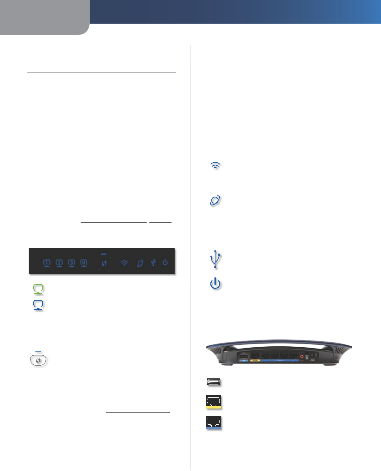
Front Panel
1, 2, 3, 4 (Green/Blue) These numbered LEDs,
corresponding with the numbered ports on
the Router’s back panel, serve two purposes.
The LED is continuously lit when the Router
is connected to a device through that port. It
flashes to indicate network activity over that
port. The LED lights up green when the port is
connected to a gigabit port or blue when the
port is connected to a 10/100 port.
Wi-Fi Protected Setup Button If you have
client devices, such as wireless adapters,
that support Wi-Fi Protected Setup, then you
can use the Wi-Fi Protected Setup button to
automatically configure wireless security for
your wireless network(s).
To use Wi-Fi Protected Setup, run the Setup
Wizard, or refer to Wi-Fi Protected Setup,
page 13.
Wi-Fi Protected Setup LED (Blue/Amber) The
LED flashes blue for two minutes during the Wi-Fi
Protected Setup process and lights up blue when
the Wi-Fi Protected Setup process is successful.
The LED lights up amber if there is an error
during the Wi-Fi Protected Setup process. Make
sure the client device supports Wi-Fi Protected
Setup. Wait until the LED is off, and then try again.
The LED flashes when a Wi-Fi Protected Setup
session is active. The Router supports one
session at a time. Wait until the LED is solidly lit,
or off before starting the next Wi-Fi Protected
Setup session.
Wireless (Blue) The Wireless LED lights up
when the wireless feature is enabled. It flashes
when the Router sends or receives data over
the network.
Internet (Green/Blue) The Internet LED lights
up when there is a connection made through
the Internet port. It flashes to indicate network
activity over the Internet port. The LED lights up
green when the port is connected to a gigabit
port or blue when the port is connected to a
10/100 port.
USB (Blue) The USB LED lights up when a USB
device is attached. It flashes when data is being
sent to or received from this device.
Power (Blue) The Power LED lights up when
the Router is powered on. When the Router goes
through its self-diagnostic mode during every
boot-up, the LED flashes. When the diagnostic
is complete, the LED is continuously lit.
Back Panel
USB Port The USB port connects to a USB
storage device.
Internet The Internet port is where you
connect your cable or DSL Internet connection.
1, 2, 3, 4 Using network cables, these Ethernet
ports (1, 2, 3, 4) connect the Router to computers
on your wired network and other Ethernet
network devices.
Chapter 1 Product Overview
4
Simultaneous Dual-Band Wireless-N Gigabit Router
Reset There are two ways to reset the
Router’s factory defaults. Either press and
hold the Reset Button for approximately five
seconds, or restore the defaults from the
Administration > Factory Defaults screen in
the Router’s browser-based utility (refer to
Administration > Factory Defaults, page 32).
Power Switch Press I the end to power on the
Router. Press the O end to power off the Router.
Power The Power port is where you connect
the power adapter.
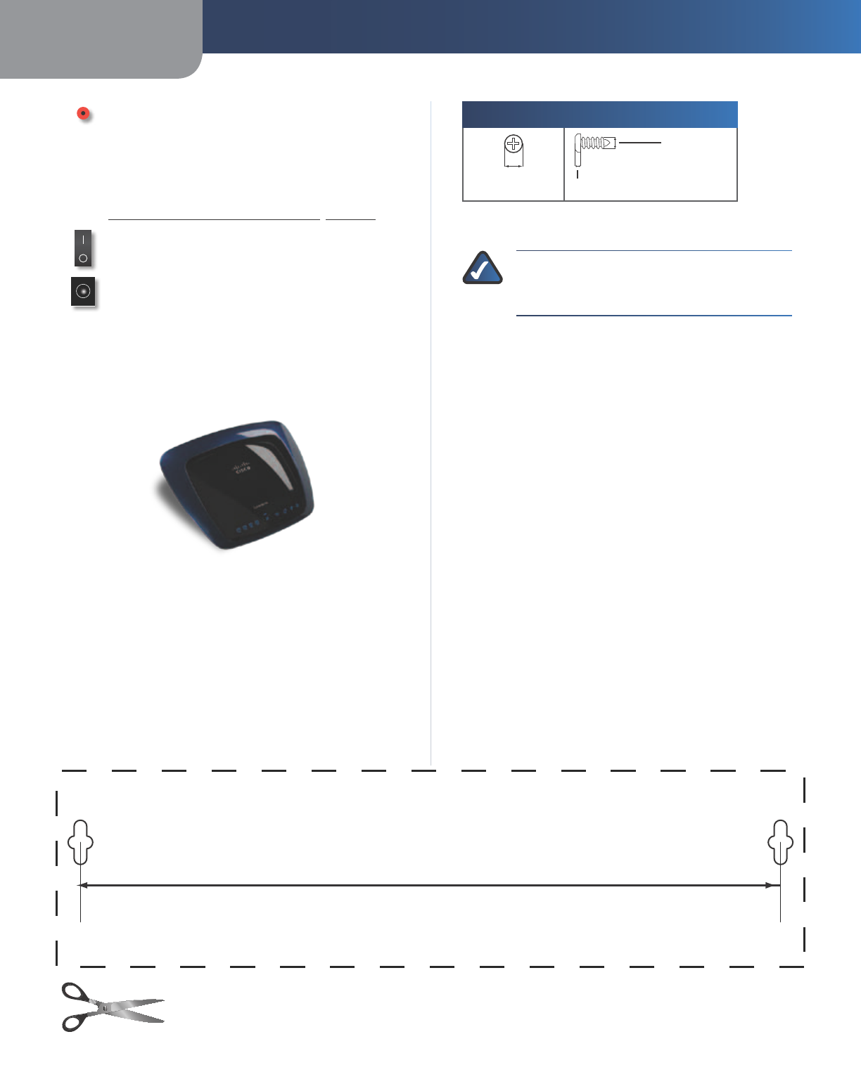
Horizontal Placement
The Router has four rubber feet on its bottom panel. Place
the Router on a level surface near an electrical outlet.
Wall-Mounting Placement
The Router has two wall-mount slots on its bottom
panel. The distance between the slots is 175.56 mm
(6.91 inches).
Two screws are needed to mount the Router.
Suggested Mounting Hardware
2.5-3.0 mm
4-5 mm 1-1.5 mm
† Note: Mounting hardware illustrations are not true
to scale.
NOTE: Linksys is not responsible for damages
incurred by unsecured wall-mounting
hardware.
Follow these instructions:
1. Determine where you want to mount the Router. Make
sure that the wall you use is smooth, flat, dry, and
sturdy. Also make sure the location is within reach of
an electrical outlet.
2. Drill two holes into the wall. Make sure the holes are
175.56 mm (6.91 inches) apart.
3. Insert a screw into each hole and leave 3 mm
(0.12 inches) of its head exposed.
4. Position the Router so the wall-mount slots line up
with the two screws.
5. Place the wall-mount slots over the screws and slide
the Router down until the screws fit snugly into the
wall-mount slots.
175.56 mm
(6.91 in)
Wall-Mounting Template
Print this page at 100% size.
Cut along the dotted line, and place on the wall to drill precise spacing.
Chapter 2 Wireless Security Checklist
5
Simultaneous Dual-Band Wireless-N Gigabit Router
Chapter 2:
Wireless Security Checklist
Wireless networks are convenient and easy to install, so
homes with high-speed Internet access are adopting them
at a rapid pace. Because wireless networking operates by
sending information over radio waves, it can be more
vulnerable to intruders than a traditional wired network.
Like signals from your cellular or cordless phones, signals
from your wireless network can also be intercepted. Since
you cannot physically prevent someone from connecting
to your wireless network, you need to take some additional
steps to keep your network secure.
1. Change the default wireless
network name or SSID
Wireless devices have a default wireless network name
or Service Set Identifier (SSID) set by the factory. This
is the name of your wireless network, and can be up
to 32 characters in length. Linksys wireless products
use linksys as the default wireless network name. You
should change the wireless network name to something
unique to distinguish your wireless network from other
wireless networks that may exist around you, but do not
use personal information (such as your Social Security
number) because this information may be available for
anyone to see when browsing for wireless networks.
2. Change the default password
For wireless products such as access points and routers,
you will be asked for a password when you want to change
their settings. These devices have a default password set
by the factory. The Linksys default password is admin.
Hackers know these defaults and may try to use them
to access your wireless device and change your network
settings. To thwart any unauthorized changes, customize
the device’s password so it will be hard to guess.
3. Enable MAC address filtering
Linksys routers give you the ability to enable Media Access
Control (MAC) address filtering. The MAC address is a
unique series of numbers and letters assigned to every
networking device. With MAC address filtering enabled,
wireless network access is provided solely for wireless
devices with specific MAC addresses. For example, you can
specify the MAC address of each computer in your home
so that only those computers can access your wireless
network.
4. Enable encryption
Encryption protects data transmitted over a wireless
network. Wi-Fi Protected Access (WPA/WPA2) and Wired
Equivalent Privacy (WEP) offer different levels of security
for wireless communication.
A network encrypted with WPA/WPA2 is more secure
than a network encrypted with WEP, because WPA/WPA2
uses dynamic key encryption. To protect the information
as it passes over the airwaves, you should enable the
highest level of encryption supported by your network
equipment.
WEP is an older encryption standard and may be the
only option available on some older devices that do not
support WPA.
General Network Security Guidelines
Wireless network security is useless if the underlying
network is not secure.
•Password protect all computers on the network and
individually password protect sensitive files.
•Change passwords on a regular basis.
•Install anti-virus software and personal firewall
software.
•Disable file sharing (peer-to-peer). Some applications
may open file sharing without your consent and/or
knowledge.
Additional Security Tips
•Keep wireless routers, access points, or gateways away
from exterior walls and windows.
•Turn wireless routers, access points, or gateways
off when they are not being used (at night, during
vacations).
•Use strong passphrases that are at least eight
characters in length. Combine letters and numbers to
avoid using standard words that can be found in the
dictionary.
WEB: For more information on wireless security,
visit www.linksysbycisco.com/security
Chapter 3 Advanced Configuration
6
Simultaneous Dual-Band Wireless-N Gigabit Router
Chapter 3:
Advanced Configuration
After setting up the Router with the Setup Wizard (located
on the CD-ROM), the Router will be ready for use. If you
would like to change its advanced settings, use the
Router’s browser-based utility. This chapter describes each
web page of the utility and each page’s key functions. You
can access the utility via a web browser on a computer
connected to the Router.
The browser-based utility has these main tabs: Setup,
Wireless, Security, Storage, Access Restrictions,
Applications & Gaming, Administration, and Status.
Additional tabs will be available after you click one of the
main tabs.
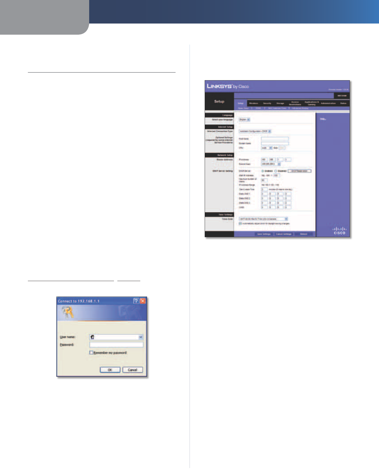
How to Access the Browser-Based Utility
To access the browser-based utility, launch the web
browser on your computer, and enter the Router’s default
IP address, 192.168.1.1 or WRT610N in the Address field.
Then press Enter.
A login screen will appear. (Non-Windows XP users will
see a similar screen.) Leave the User name field blank.
Then enter the password you set up during the Setup
Wizard. (If you did not run the Setup Wizard, then use the
default password, admin. You can set a new password
on the Administration > Management screen. Refer to
Administration > Management, page 30.) Click OK to
continue.
Password Screen
Setup > Basic Setup
The first screen that appears is the Basic Setup screen. This
allows you to change the Router’s general settings.
Setup > Basic Setup
Language
Language
To use a different language, select one from
the drop-down menu. The language of the browser-based
utility will change five seconds after you select another
language.
Click Save Settings to apply your changes, or click Cancel
Changes to clear your changes.
Internet Setup
The Internet Setup section configures the Router to your
Internet connection. Most of this information can be
obtained through your Internet Service Provider (ISP).
Internet Connection Type
Select the type of Internet connection your ISP provides
from the drop-down menu. The available types are:
•Automatic Configuration - DHCP
•Static IP
•PPPoE
•PPTP
•L2TP
•Telstra Cable
Chapter 3 Advanced Configuration
7
Simultaneous Dual-Band Wireless-N Gigabit Router
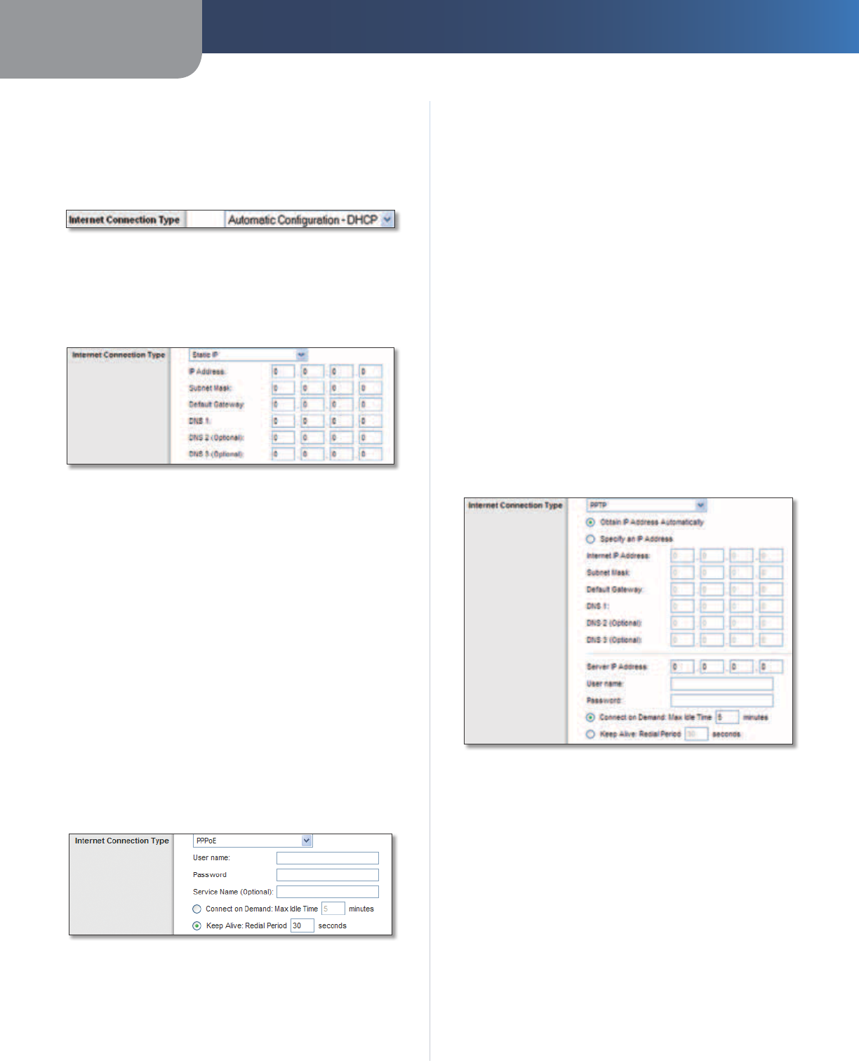
Automatic Configuration - DHCP
The default Internet Connection Type is set to Automatic
Configuration - DHCP. Keep the default only if your
ISP supports DHCP or if you connect using a dynamic IP
Address. (This option usually applies to cable connections.)
Internet Connection Type > Automatic Configuration - DHCP
Static IP
If you are required to use a permanent IP address to
connect to the Internet, select Static IP.
Internet Connection Type > Static IP
IP Address This is the Router’s IP address, when seen
from the Internet. Your ISP will provide you with the IP
address you need to enter here.
Subnet Mask This is the Router’s Subnet Mask, as seen
by users on the Internet (including your ISP). Your ISP will
provide you with the Subnet Mask.
Default Gateway Your ISP will provide you with the
Gateway address, which is the ISP server’s IP address.
DNS Your ISP will provide you with at least one DNS
(Domain Name System) server IP address.
PPPoE
Some DSL-based ISPs use PPPoE (Point-to-Point Protocol
over Ethernet) to establish Internet connections. If you are
connected to the Internet through a DSL line, check with
your ISP to see if they use PPPoE. If they do, you will have
to enable PPPoE.
Internet Connection Type > PPPoE
User Name and Password Enter the User Name and
Password provided by your ISP.
Service Name (optional) If provided by your ISP, enter
the Service Name.
Connect on Demand: Max Idle Time You can configure
the Router to cut the Internet connection after it has
been inactive for a specified period of time (Max Idle
Time). If your Internet connection has been terminated
due to inactivity, Connect on Demand enables the Router
to automatically re-establish your connection as soon
as you attempt to access the Internet again. To use this
option, select Connect on Demand. In the Max Idle Time
field, enter the number of minutes you want to elapse
before your Internet connection terminates. The default is
5 minutes.
Keep Alive: Redial Period If you select this option, the
Router will periodically check your Internet connection. If
you are disconnected, then the Router will automatically
re-establish your connection. To use this option, select
Keep Alive. In the Redial Period field, specify how often
the Router should check the Internet connection. The
default is 30 seconds.
PPTP
Point-to-Point Tunneling Protocol (PPTP) is a service that
applies to connections in Europe only.
Internet Connection Type > PPTP
If your ISP supports DHCP or you are connecting through
a dynamic IP address, then select Obtain an IP Address
Automatically. If you are required to use a permanent IP
address to connect to the Internet, then select Specify an
IP Address. Then configure the following:
Internet IP Address This is the Router’s IP address, as
seen from the Internet. Your ISP will provide you with the
IP Address you need to specify here.
Subnet Mask This is the Router’s Subnet Mask, as seen
by users on the Internet (including your ISP). Your ISP will
provide you with the Subnet Mask.
Default Gateway Your ISP will provide you with the
Gateway address, which is the ISP server’s IP address.
Chapter 3 Advanced Configuration
8
Simultaneous Dual-Band Wireless-N Gigabit Router
DNS Your ISP will provide you with at least one DNS
(Domain Name System) Server IP address.
Server IP Address Your ISP will provide you with the
Server IP Address.
User Name and Password Enter the User Name and
Password provided by your ISP.
Connect on Demand: Max Idle Time You can configure
the Router to cut the Internet connection after it has
been inactive for a specified period of time (Max Idle
Time). If your Internet connection has been terminated
due to inactivity, Connect on Demand enables the Router
to automatically re-establish your connection as soon
as you attempt to access the Internet again. To use this
option, select Connect on Demand. In the Max Idle Time
field, enter the number of minutes you want to elapse
before your Internet connection terminates. The default is
5 minutes.
Keep Alive: Redial Period If you select this option, the
Router will periodically check your Internet connection. If
you are disconnected, then the Router will automatically
re-establish your connection. To use this option, select
Keep Alive. In the Redial Period field, specify how often
the Router should check the Internet connection. The
default is 30 seconds.
L2TP
L2TP is a service that applies to connections in Israel only.
Internet Connection Type > L2TP
Server IP Address This is the IP address of the L2TP
Server. Your ISP will provide you with the IP Address you
need to specify here.
User Name and Password Enter the User Name and
Password provided by your ISP.
Connect on Demand: Max Idle Time You can configure
the Router to cut the Internet connection after it has
been inactive for a specified period of time (Max Idle
Time). If your Internet connection has been terminated
due to inactivity, Connect on Demand enables the Router
to automatically re-establish your connection as soon
as you attempt to access the Internet again. To use this
option, select Connect on Demand. In the Max Idle Time
field, enter the number of minutes you want to elapse
before your Internet connection terminates. The default is
5 minutes.
Keep Alive: Redial Period If you select this option, the
Router will periodically check your Internet connection. If
you are disconnected, then the Router will automatically
re-establish your connection. To use this option, select
Keep Alive. In the Redial Period field, specify how often
the Router should check the Internet connection. The
default is 30 seconds.
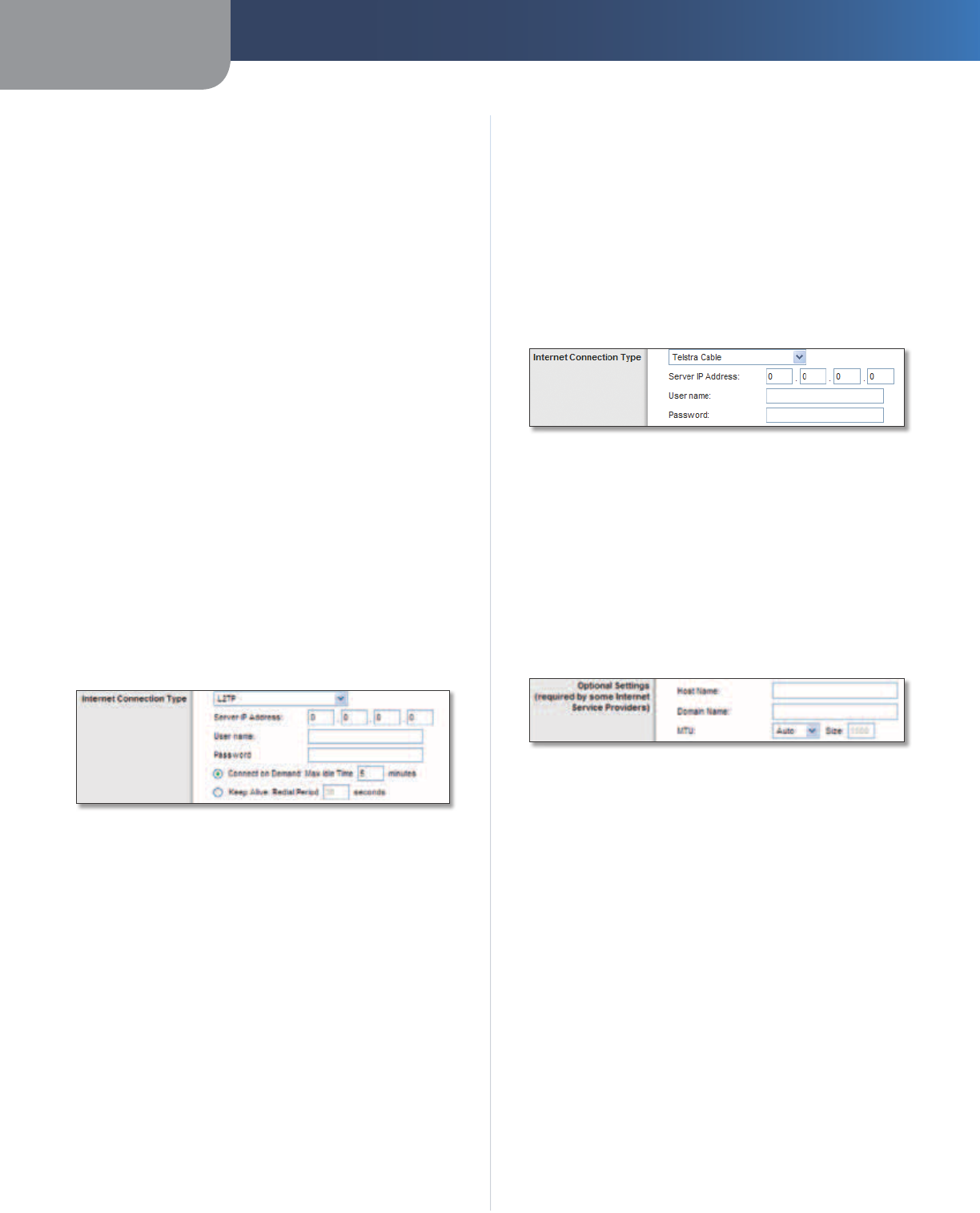
Telstra Cable
Telstra Cable is a service that applies to connections in
Australia only.
Internet Connection Type > Telstra Cable
Server IP Address This is the IP address of the Telstra
Cable. Your ISP will provide you with the IP Address you
need to specify here.
User Name and Password Enter the User Name and
Password provided by your ISP.
Optional Settings
Some of these settings may be required by your ISP. Verify
with your ISP before making any changes.
Optional Settings
Host Name/Domain Name These fields allow you to
supply a host and domain name for the Router. Some ISPs,
usually cable ISPs, require these names as identification.
You may have to check with your ISP to see if your
broadband Internet service has been configured with a
host and domain name. In most cases, leaving these fields
blank will work.
MTU MTU is the Maximum Transmission Unit. It specifies
the largest packet size permitted for Internet transmission.
Select Manual if you want to manually enter the largest
packet size that is transmitted. To have the Router select
the best MTU for your Internet connection, keep the
default setting, Auto.
Chapter 3 Advanced Configuration
9
Simultaneous Dual-Band Wireless-N Gigabit Router
Size When Manual is selected in the MTU field, this option
is enabled. Leave this value in the 1200 to 1500 range. The
default size depends on the Internet Connection Type:
•DHCP, Static IP, or Telstra: 1500
•PPPoE: 1492
•PPTP or L2TP: 1460
Network Setup
The Network Setup section changes the settings on
the network connected to the Router’s Ethernet ports.
Wireless Setup is performed through the Wireless tab
(refer to Wireless > Basic Wireless Settings, page 12).
Router Address
This presents both the Router’s IP Address and Subnet
Mask, as seen by your network. The default Router IP
address is 192.168.1.1.
Router IP Address
DHCP Server Settings
The settings allow you to configure the Router’s Dynamic
Host Configuration Protocol (DHCP) server function. The
Router can be used as a DHCP server for your network. A
DHCP server automatically assigns an IP address to each
computer on your network. If you choose to enable the
Router’s DHCP server option, make sure there is no other
DHCP server on your network.
Network Address Server Settings (DHCP)
DHCP Server DHCP is enabled by factory default. If you
already have a DHCP server on your network, or you do
not want a DHCP server, then select Disabled (no other
DHCP features will be available).
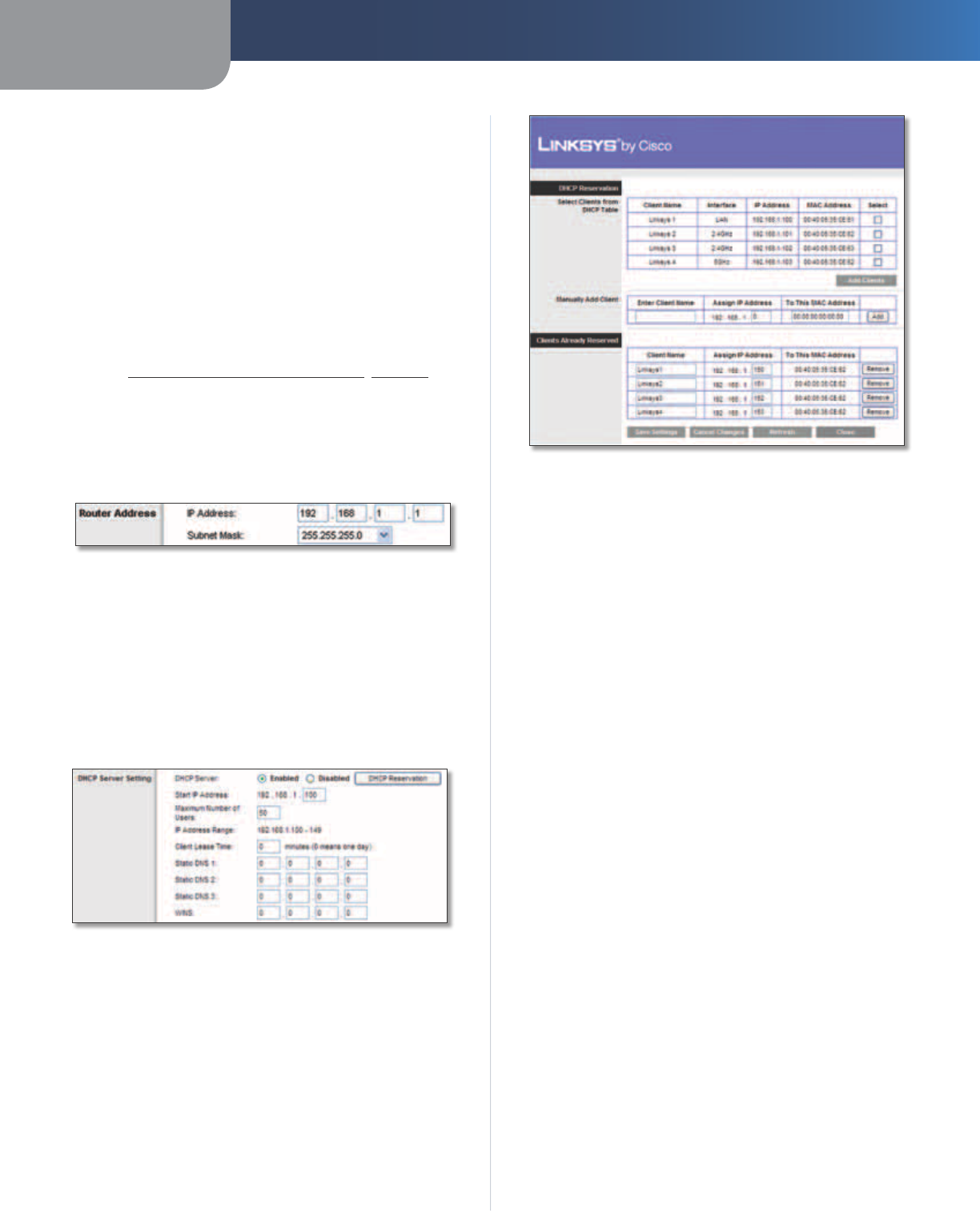
DHCP Reservation Click DHCP Reservation if you want
to assign a fixed local IP address to a MAC address.
DHCP Reservation
You will see a list of DHCP clients with the following
information: Client Name, Interface, IP Address, and
MAC Address.
DHCP Reservation
•Select Clients from DHCP Table Click the Select
check box to reserve a client’s IP address. Then click
Add Clients.
•Manually Adding Client To manually assign an IP
address, enter the client’s name in the Enter Client
Name field. Enter the IP address you want it to have in
the Assign IP Address field. Enter its MAC address in the
To This MAC Address field. Then click Add.
Clients Already Reserved
A list of DHCP clients and their fixed local IP addresses
will be displayed at the bottom of the screen. If you
want to remove a client from this list, click Remove.
Click Save Settings to apply your changes, or click
Cancel Changes to clear your changes. To update
the on-screen information, click Refresh. To exit this
screen, click Close.
Start IP Address Enter a value for the DHCP server to
start with when is
suing IP addresses. Because the Router’s
default IP address is 192.168.1.1, the Start IP Address must
be 192.168.1.2 or greater, but smaller than 192.168.1.253.
The default is 192.168.1.100
.
Maximum Number of Users Enter the maximum
number of computers that you want the DHCP server to
assign IP addresses to. This number cannot be greater
than 253. The default is 50.
IP Address Range The range of available IP addresses is
displayed.
Client Lease Time The Client Lease Time is the amount
of time a network user will be allowed connection to the
Router with their current dynamic IP address. Enter the
amount of time, in minutes, that the user will be “leased”
this dynamic IP address. After the time is up, the user will
be automatically assigned a new dynamic IP address, or
Chapter 3 Advanced Configuration
10
Simultaneous Dual-Band Wireless-N Gigabit Router
the lease will be renewed. The default is 0 minutes, which
means one day.
Static DNS (1-3)
The Domain Name System (DNS) is how
the Internet translates domain or website names into
Internet addresses or URLs. Your ISP will provide you with at
least one DNS Server IP Address. If you wish to use another,
enter that IP Address in one of these fields. You can enter up
to three DNS Server IP Addresses here. The Router will use
these for quicker access to functioning DNS servers
.
WINS The Windows Internet Naming Service (WINS)
manages each computer’s interaction with the Internet. If
you use a WINS server, enter that server’s IP address here.
Otherwise, leave this blank.
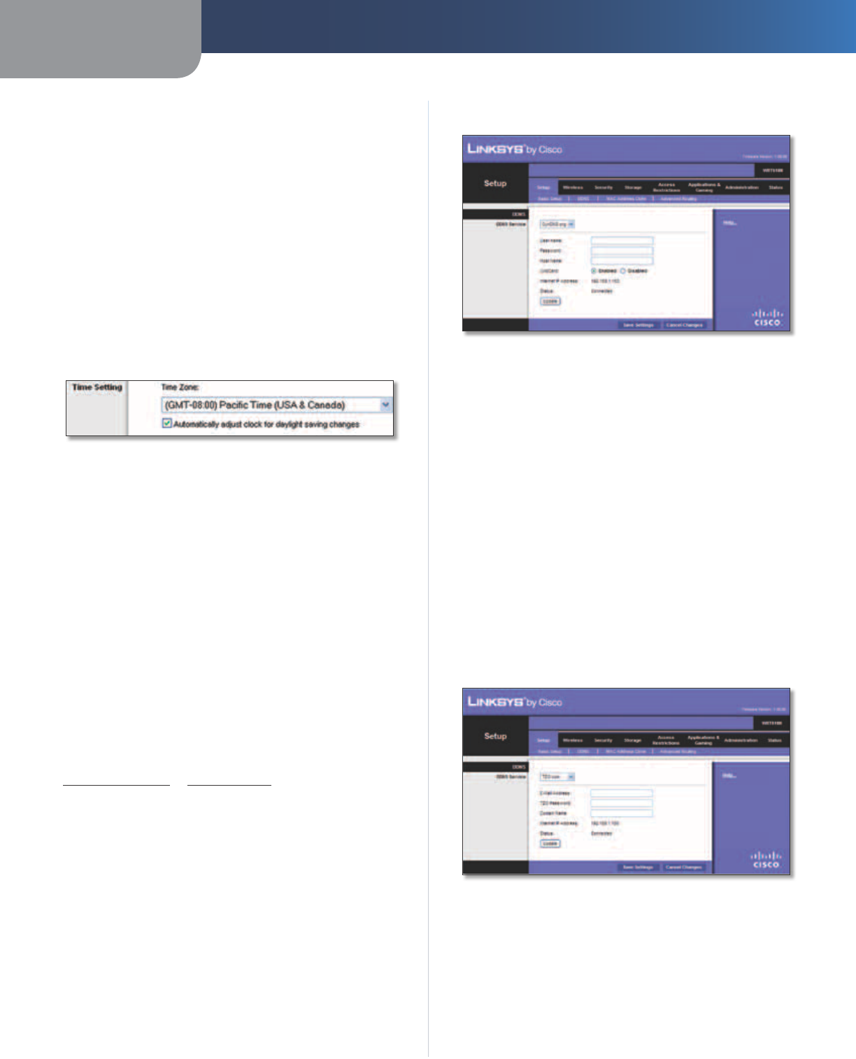
Time Setting
Time Setting
Time Zone Select the time zone in which your network
functions from this drop-down menu.
Automatically adjust clock for daylight saving
changes Select this option to have the Router
automatically adjust for daylight saving time.
Click Save Settings to apply your changes, or click Cancel
Changes to clear your changes.
Setup > DDNS
The Router offers a Dynamic Domain Name System (DDNS)
feature. DDNS lets you assign a fixed host and domain
name to a dynamic Internet IP address. It is useful when
you are hosting your own website, FTP server, or other
server behind the Router.
Before you can use this feature, you need to sign
up for DDNS service with a DDNS service provider,
www.dyndns.org or www.tzo.com. If you do not want to
use this feature, keep the default, Disabled.
DDNS
DDNS Service
If your DDNS service is provided by DynDNS.org, then
select DynDNS.org from the drop-down menu. If your
DDNS service is provided by TZO, then select TZO.com.
The features available on the DDNS screen will vary,
depending on which DDNS service provider you use.
DynDNS.org
Setup > DDNS > DynDNS
User Name Enter the User Name for your DDNS account.
Password Enter the Password for your DDNS account.
Host Name The DDNS URL assigned by the DDNS service
is displayed.
WildCard Select Enabled to enable this feature or
Disabled to disable it.
Internet IP Address The Router’s Internet IP address is
displayed here. Because it is dynamic, it will change.
Status The status of the DDNS service connection is
displayed.
Update To manually trigger an update, click Update.
Click Save Settings to apply your changes, or click Cancel
Changes to clear your changes.
TZO.com
Setup > DDNS > TZO
E-mail Address, TZO Password, and Domain
Name Enter the settings of the account you set up with
TZO.
Internet IP Address The Router’s Internet IP address is
displayed here. Because it is dynamic, it will change.
Status The status of the DDNS service connection is
displayed.
Chapter 3 Advanced Configuration
11
Simultaneous Dual-Band Wireless-N Gigabit Router
Update To manually trigger an update, click Update.
Click Save Settings to apply your changes, or click Cancel
Changes to clear your changes.
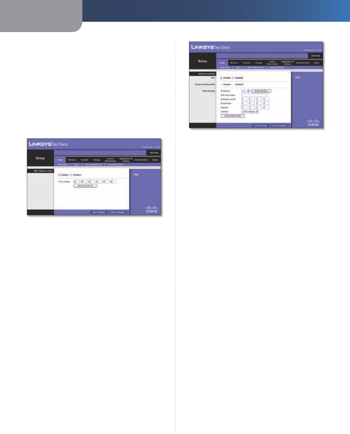
Setup > MAC Address Clone
Some ISPs will require you to register a MAC address
in order to access the Internet. A MAC address is a
12-digit code assigned to a unique piece of hardware for
identification. If you do not wish to re-register the MAC
address with your ISP, you can use the MAC Address Clone
feature to assign the currently registered MAC address to
the Router.
Setup > MAC Address Clone
MAC Address Clone
Enabled/Disabled To have the MAC address cloned,
select Enabled.
MAC Address Enter the MAC address registered with
your ISP here.
Clone My PC’s MAC Click this button to clone the MAC
address of the computer you are using.
Click Save Settings to apply your changes, or click Cancel
Changes to clear your changes.
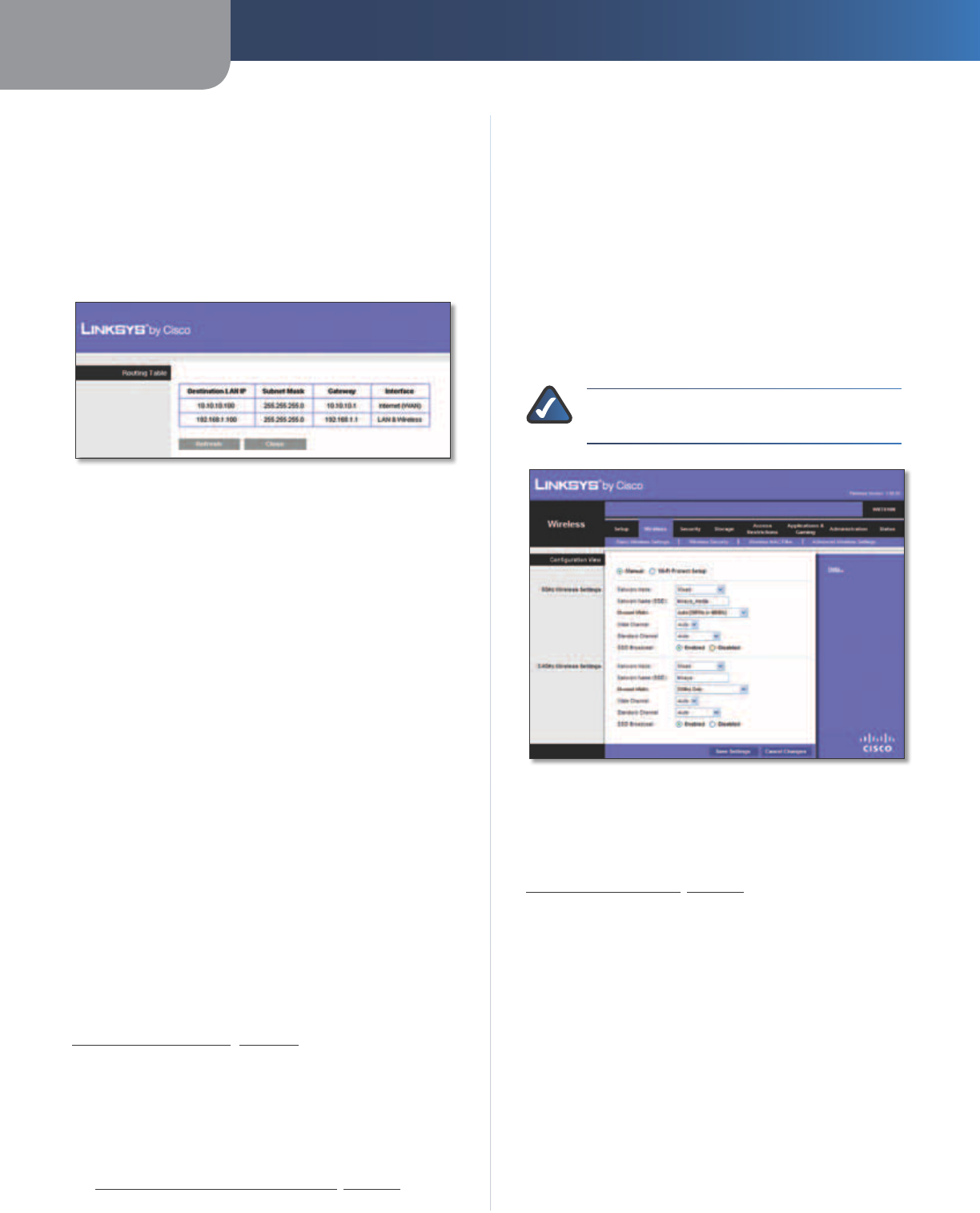
Setup > Advanced Routing
This screen is used to set up the Router’s advanced
functions. Operating Mode allows you to select the
type(s) of advanced functions you use. Dynamic Routing
automatically adjusts how packets travel on your network.
Static Routing sets up a fixed route to another network
destination.
Setup > Advanced Routing
Advanced Routing
NAT
Enabled/Disabled If this Router is hosting your network’s
connection to the Internet, keep the default, Enabled. If
another router exists on your network, select Disabled.
When the NAT setting is disabled, dynamic routing will be
enabled.
Dynamic Routing (RIP)
Enabled/Disabled This feature enables the Router to
automatically adjust to physical changes in the network’s
layout and exchange routing tables with the other
router(s). The Router determines the network packets’
route based on the fewest number of hops between
the source and the destination. When the NAT setting is
enabled, the Dynamic Routing feature is automatically
disabled. When the NAT setting is disabled, this feature
is available. Select Enabled to use the Dynamic Routing
feature.
Static Routing
A static route is a pre-determined pathway that network
information must travel to reach a specific host or
network. Enter the information described below to set up
a new static route.
Route Entry To set up a static route between the Router
and another network, select a number from the drop-
down list. Click Delete This Entry to delete a static route.
Enter Route Name Enter a name for the Route here,
using a maximum of 25 alphanumeric characters.
Destination LAN IP The Destination LAN IP is the address
of the remote network or host to which you want to assign
a static route.
Subnet Mask The Subnet Mask determines which
portion of a Destination LAN IP address is the network
portion, and which portion is the host portion.
Chapter 3 Advanced Configuration
12
Simultaneous Dual-Band Wireless-N Gigabit Router
Gateway This is the IP address of the gateway device that
allows for contact between the Router and the remote
network or host.
Interface This interface tells you whether the Destination
IP Address is on the LAN & Wireless (Ethernet and wireless
networks) or the WAN (Internet).
Click Show Routing Table to view the static routes you
have already set up.
Routing Table
Routing Table
For each route, the Destination LAN IP address, Subnet
Mask, Gateway, and Interface are displayed. Click
Refresh to update the information. Click Close to exit
this screen.
Click Save Settings to apply your changes, or click Cancel
Changes to clear your changes.
Wireless > Basic Wireless Settings
The basic settings for wireless networking are set on this
screen.
There are two ways to configure the Router’s wireless
network(s), manual and Wi-Fi Protected Setup.
Wi-Fi Protected Setup is a feature that makes it easy to set
up your wireless network. If you have client devices, such
as wireless adapters, that support Wi-Fi Protected Setup,
then you can use Wi-Fi Protected Setup.
Simultaneous Networks
For more wireless bandwidth, the Router can create two
simultaneous yet separate Wireless-N networks, one using
the Wireless-N 5 GHz band and one using the Wireless-N
2.4 GHz band. You can use Wi-Fi Protected Setup to
easily configure and connect to both networks (refer to
Wi-Fi Protected Setup, page 13), or you can manually
configure the Router.
If you use manual configuration, then set up each network
with the following:
•Unique Network Name (SSID)
•Wireless security settings (refer to
5 GHz or 2.4 GHz Wireless Security, page 14)
Decide which computers and other wireless devices
should join which network. Wireless-N devices support
both the 5 GHz and 2.4 GHz bands, so they can join either
the 5 GHz or 2.4 GHz network. Wireless-G and Wireless-B
devices support only the 2.4 GHz band, so they should
join the 2.4 GHz network. Wireless-A devices support only
the 5 GHz band, so they should join the 5 GHz network.
For the 5 GHz network, configure all computers and other
wireless devices with the same 5 GHz Network Name
(SSID) and wireless security settings. For the 2.4 GHz
network, configure all computers and other wireless
devices with the same 2.4 GHz Network Name (SSID) and
wireless security settings.
NOTE: Make sure each network uses a unique
Network Name (SSID).
Wireless > Basic Wireless Settings
Configuration View To manually configure your
wireless networks, select Manual. Proceed to the Wireless
Configuration (Manual) section. To use Wi-Fi Protected
Setup, select Wi-Fi Protected Setup. Proceed to
Wi-Fi Protected Setup, page 13.
Wireless Configuration (Manual)
If you set the Configuration View to Manual, the Basic
Wireless Settings screen displays the following fields.
5 GHz or 2.4 GHz Wireless Settings
The same settings are available for the 5 GHz and 2.4 GHz
radio bands. The 5 GHz Wireless settings set up a network
using the 5 GHz band, and the 2.4 GHz Wireless settings
set up a network using the 2.4 GHz band.
Network Mode (5 GHz) Select the wireless standards
running on your 5 GHz network. If you have both Wireless-A
and Wireless-N (5 GHz) devices in your network, keep the
default, Mixed. If you have only Wireless-A devices, select
Wireless-A Only. If you have only Wireless-N (5 GHz)
Chapter 3 Advanced Configuration
13
Simultaneous Dual-Band Wireless-N Gigabit Router
devices, select Wireless-N Only. If you do not have any
Wireless-A and Wireless-N (5GHz) devices in your network,
select Disabled.
Network Mode (2.4 GHz) Select the wireless standards
running on your 2.4 GHz network. If you have both
Wireless-B, Wireless-G and Wireless-N (2.4 GHz) devices in
your network, keep the default, Mixed. If you have only
Wireless-B devices, select Wireless-B Only. If you have
only Wireless-G devices, select Wireless-G Only. If you
have only Wireless-N (2.4 GHz) devices, select Wireless-N
Only. If you do not have any Wireless-B, Wireless-G and
Wireless-N (2.4 GHz) devices in your network, select
Disabled.
Network Name (SSID) The SSID is the network
name shared by all devices in a wireless network. It
is case-sensitive and must not exceed 32 keyboard
characters. For added security, you should change the
default network name to a unique name.
Channel Width (5 GHz) For best performance in a
network using Wireless-A and Wireless-N (5 GHz) devices,
keep the default, Auto (20MHz or 40MHz). For a channel
width of 40 MHz, select 40MHz only. For a channel width
of 20 MHz, select 20MHz only.
Channel Width (2.4 GHz) For best performance in a
network using Wireless-B, Wireless-G and Wireless-N
(2.4 GHz) devices, select Auto (20MHz or 40MHz). For
a channel width of 40 MHz, select 40MHz only. For a
channel width of 20 MHz, keep the default, 20MHz only.
Wide Channel (5 GHz) If you selected 40MHz only or Auto
(20MHz or 40MHz) for the Channel Width setting, then this
setting will be available for your primary Wireless-N (5GHz)
channel. If you are not sure which channel to select, keep
the default, Auto.
Wide Channel (2.4 GHz) If you selected 40MHz only or
Auto (20MHz or 40MHz) for the Channel Width setting,
then this setting will be available for your primary
Wireless-N (2.4 GHz) channel. If you are not sure which
channel to select, keep the default, Auto.
Standard Channel (5 GHz) Select the channel for
Wireless-A and Wireless-N (5GHz) networking. If you
selected 40MHz only or Auto (20MHz or 40MHz) for the
Channel Width setting, then the Standard Channel will be
a secondary channel for Wireless-N (5GHz). If you are not
sure which channel to select, keep the default, Auto.
Standard Channel (2.4 GHz) Select the channel
for Wireless-B, Wireless-G, and Wireless-N (2.4 GHz)
networking. If you selected 40MHz only or Auto (20MHz or
40MHz) for the Channel Width setting, then the Standard
Channel will be a secondary channel for Wireless-N (2.4
GHz). If you are not sure which channel to select, keep the
default, Auto.
SSID Broadcast When wireless clients survey the local
area for wireless networks to associate with, they will
detect the SSID broadcast by the Router. To broadcast the
Router’s SSID, keep the default, Enabled. If you do not
want to broadcast the Router’s SSID, then select Disabled.
Click Save Settings to apply your changes, or click Cancel
Changes to clear your changes.
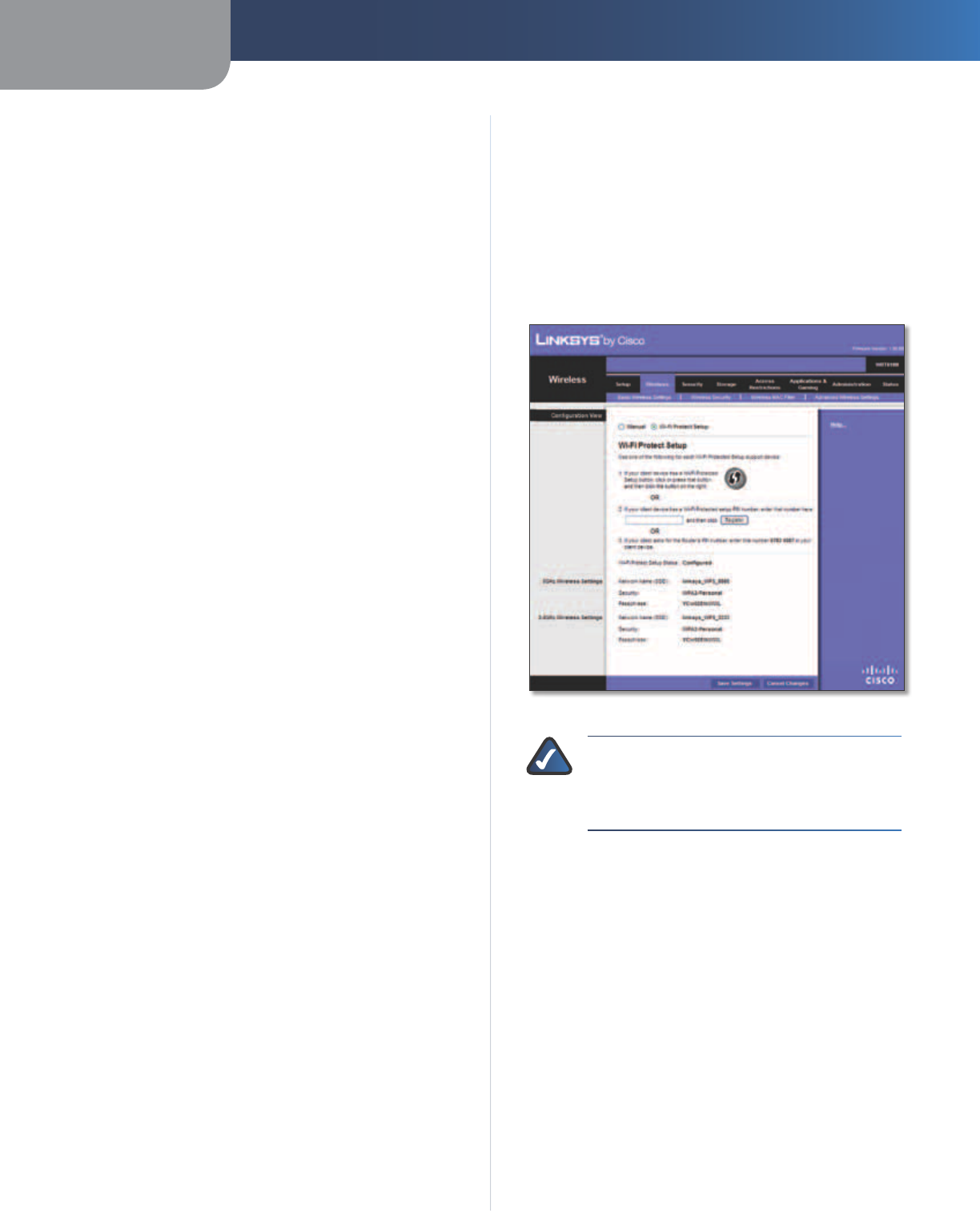
Wi-Fi Protected Setup
There are three methods available. Use the method that
applies to the client device you are configuring.
Wireless > Basic Wireless Settings (Wi-Fi Protected Setup)
NOTE: Wi-Fi Protected Setup configures one
client device at a time. Repeat the instructions
for each client device that supports Wi-Fi
Protected Setup.
Method #1 Use this method if your client device has a
Wi-Fi Protected Setup button.
1. Click or press the Wi-Fi Protected Setup button on
the client device.
2. Click the Wi-Fi Protected Setup button on the
Router’s Wi-Fi Protected Setup screen.
3. After the client device has been configured, click OK
on the Router’s Wi-Fi Protected Setup screen. Then refer
back to your client device or its documentation for
further instructions.
Method #2 Use this method if your client device has a
Wi-Fi Protected Setup PIN number.
1. Enter the PIN number from the client device in the
field on the Router’s Wi-Fi Protected Setup screen.
2. Click the Register button on the Router’s Wi-Fi
Protected Setup screen.
Chapter 3 Advanced Configuration
14
Simultaneous Dual-Band Wireless-N Gigabit Router
3. After the client device has been configured, click OK
on the Router’s Wi-Fi Protected Setup screen. Then refer
back to your client device or its documentation for
further instructions.
Method #3 Use this method if your client device asks for
the Router’s PIN number.
1. On the client device, enter the PIN number listed on
the Router’s Wi-Fi Protected Setup screen. (It is also
listed on the label on the bottom of the Router.)
2. After the client device has been configured, click OK
on the Router’s Wi-Fi Protected Setup screen. Then refer
back to your client device or its documentation for
further instructions.
The Wi-Fi Protected Setup Status, Network Name (SSID),
Security, and Passphrase are displayed at the bottom of
the screen.
NOTE: If you have client devices that do not
support Wi-Fi Protected Setup, note the wireless
settings, and then manually configure those
client devices.
Wireless > Wireless Security
The wireless security settings configure the security
of your wireless network(s). The Router supports the
following wireless security options: WPA2 Personal, WPA
Personal, WPA2 Enterprise, WPA Enterprise, RADIUS, and
WEP. WPA (Wi-Fi Protected Access) is a stronger security
standard than WEP (Wireless Equivalent Privacy), and
WPA2 is even more secure than WPA. RADIUS is Remote
Authentication Dial-In User Service.
5 GHz or 2.4 GHz Wireless Security
Wireless security is strongly recommended, and WPA2 is
the strongest method available. Use WPA2 if it is supported
by all of your wireless devices.
Security Mode
Select the security method for each wireless network. If
you do not want to use wireless security, keep the default,
Disabled.
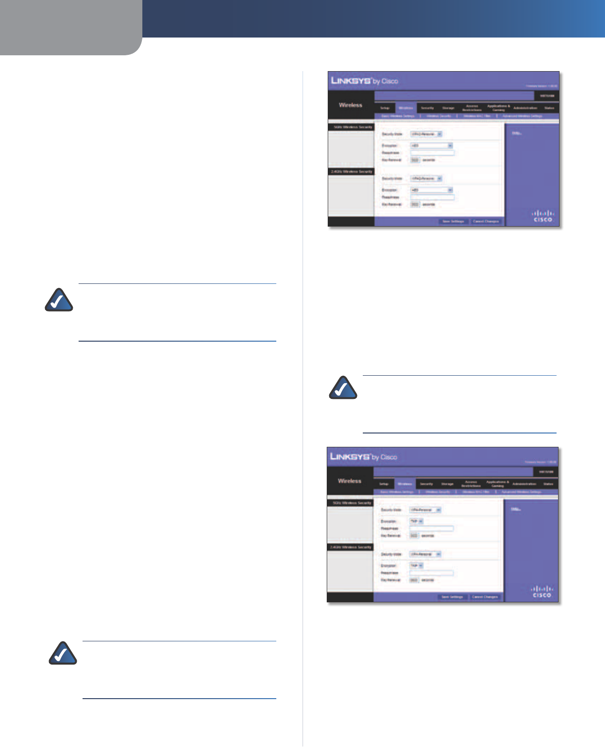
WPA2 Personal
NOTE: If you are using WPA2 or WPA, each
device in your wireless network MUST use the
same WPA method and shared key, or else the
network will not function properly.
]
WPA2 Personal
Encryption WPA2 supports two encryption methods
with dynamic encryption keys, AES or WPA-TKIP/
WPA2-AES. The default is AES.
Passphrase Enter a passphrase of 8-63 characters.
Key Renewal Enter a Key Renewal period, which instructs
the Router how often it should change the encryption
keys. The default is 3600 seconds.
WPA Personal
NOTE: If you are using WPA2 or WPA, each
device in your wireless network MUST use the
same WPA method and shared key, or else the
network will not function properly.
WPA Personal
Encryption WPA uses TKIP, an encryption method with
dynamic encryption keys.
Passphrase Enter a passphrase of 8-63 characters.
Key Renewal Enter a Key Renewal period, which instructs
the Router how often it should change the encryption
keys. The default period is 3600 seconds.
Chapter 3 Advanced Configuration
15
Simultaneous Dual-Band Wireless-N Gigabit Router
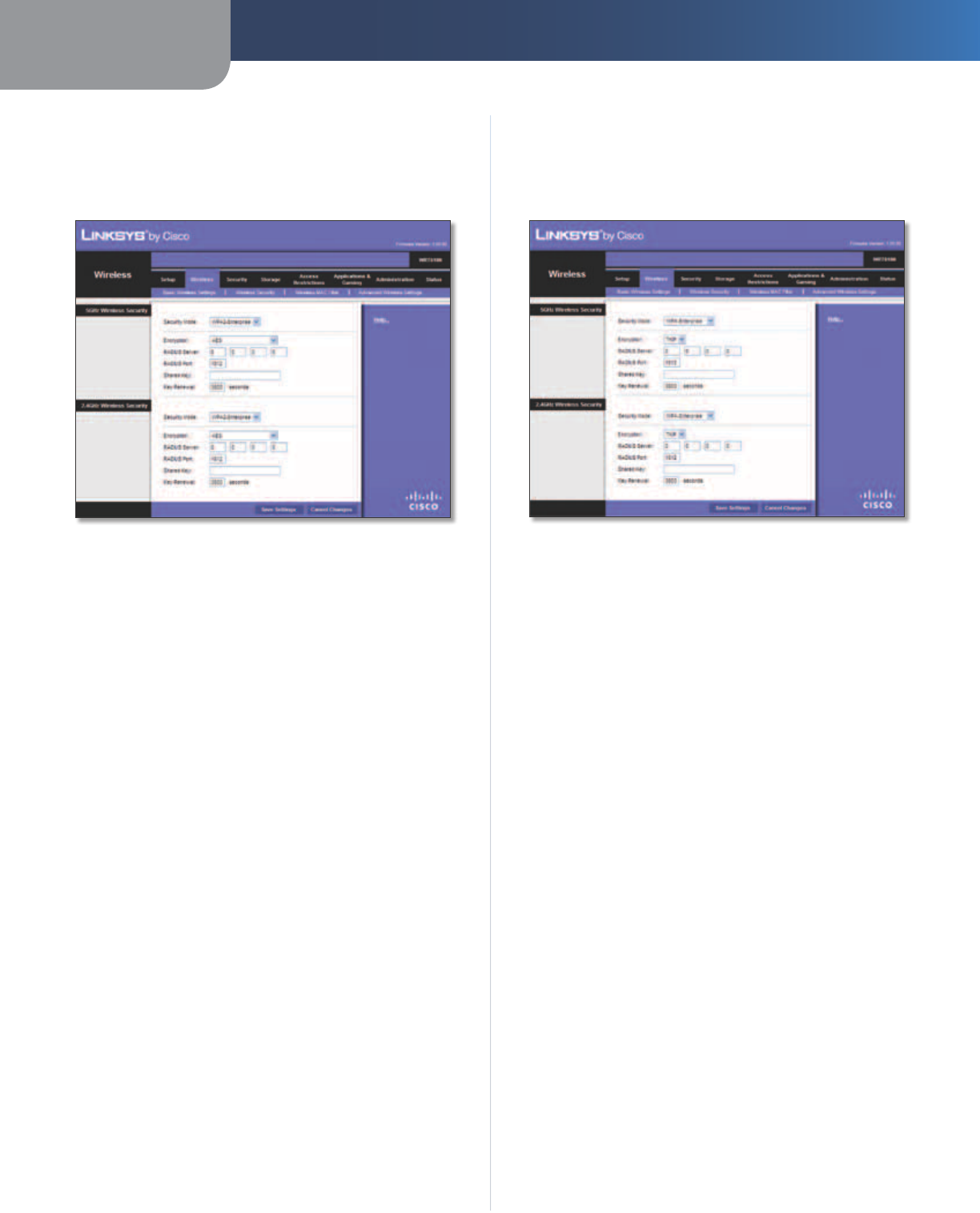
WPA2 Enterprise
This option features WPA2 used in coordination with a
RADIUS server. (This should only be used when a RADIUS
server is connected to the Router.)
WPA2 Enterprise
Encryption WPA2 supports two encryption methods
with dynamic encryption keys, AES or WPA-TKIP/
WPA2-AES. The default is AES.
RADIUS Server Enter the IP address of the RADIUS server.
RADIUS Port Enter the port number of the RADIUS
server. The default is 1812.
Shared Key Enter the key shared between the Router
and the server.
Key Renewal Enter a Key Renewal period, which instructs
the Router how often it should change the encryption
keys. The default is 3600 seconds.
WPA Enterprise
This option features WPA used in coordination with a
RADIUS server. (This should only be used when a RADIUS
server is connected to the Router.)
WPA Enterprise
Encryption WPA uses TKIP, an encryption method with
dynamic encryption keys.
RADIUS Server Enter the IP address of the RADIUS server.
RADIUS Port Enter the port number of the RADIUS
server. The default is 1812.
Shared Key Enter the key shared between the Router
and the server.
Key Renewal Enter a Key Renewal period, which instructs
the Router how often it should change the encryption
keys. The default is 3600 seconds.
Chapter 3 Advanced Configuration
16
Simultaneous Dual-Band Wireless-N Gigabit Router
RADIUS
This option features WEP used in coordination with a
RADIUS server. (This should only be used when a RADIUS
server is connected to the Router.)
IMPORTANT: If you are using WEP encryption,
each device in your wireless network MUST
use the same WEP encryption method and
encryption key, or else your wireless network will
not function properly.
RADIUS
RADIUS Server Enter the IP address of the RADIUS server.
RADIUS Port Enter the port number of the RADIUS
server. The default is 1812.
Shared Key Enter the key shared between the Router
and the server.
Encryption Select a level of WEP encryption, 64 bits
10 hex digits or 128 bits 26 hex digits. The default is
64 bits 10 hex digits.
Passphrase Enter a Passphrase to automatically generate
WEP keys. Then click Generate.
Key 1-4 If you did not enter a Passphrase, enter the WEP
key(s) manually.
TX Key Select a default TX (Transmit) Key (choose which
Key to use). The default is 1.
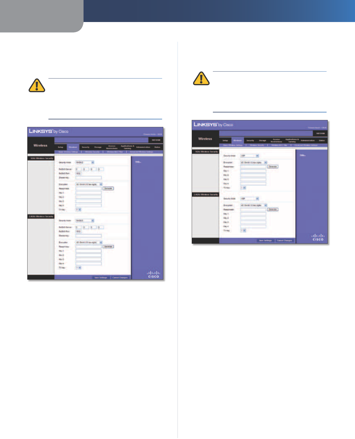
WEP
WEP is a basic encryption method, which is not as secure
as WPA.
IMPORTANT: If you are using WEP encryption,
each device in your wireless network MUST
use the same WEP encryption method and
encryption key, or else your wireless network will
not function properly.
WEP
Encryption Select a level of WEP encryption, 64 bits
10 hex digits or 128 bits 26 hex digits. The default is
64 bits 10 hex digits.
Passphrase Enter a Passphrase to automatically generate
WEP keys. Then click Generate.
Key 1-4 If you did not enter a Passphrase, enter the WEP
key(s) manually.
TX Key Select a default TX (Transmit) Key (choose which
Key to use). The default is 1.
Click Save Settings to apply your changes, or click Cancel
Changes to clear your changes.
Chapter 3 Advanced Configuration
17
Simultaneous Dual-Band Wireless-N Gigabit Router
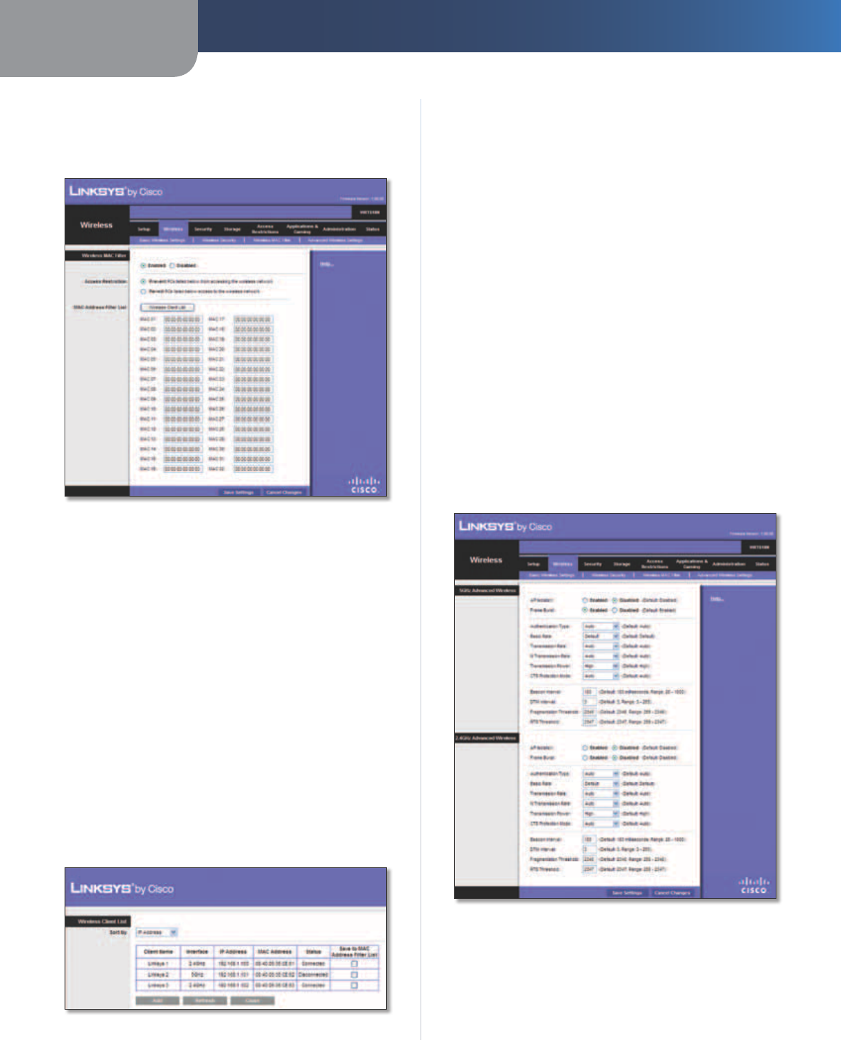
Wireless > Wireless MAC Filter
Wireless access can be filtered (restricted) by specifying
the MAC addresses of the devices in your wireless network.
Wireless > Wireless MAC Filter
Wireless MAC Filter
Enabled/Disabled
To filter wireless users by MAC address,
either permitting or blocking access, click Enabled. If you
do not wish to filter users by MAC address, keep the default
setting, Disabled
.
Access Restriction
Prevent PCs listed below from accessing the wireless
network Select this to block wireless access by MAC
address. This option is enabled by default.
Permit PCs listed below access to the wireless
network Select this to allow wireless access by MAC
address. This option is disabled by default.
MAC Address Filter List
Wireless Client List Click this to open the Wireless Client
List screen.
Wireless Client List
Wireless Client List
This screen shows computers and other devices on
the wireless network. The list can be sorted by Client
Name, Interface, IP Address, MAC Address, and Status.
Select Save to MAC Address Filter List for any device
you want to add to the MAC Address Filter List. Then
click Add.
To update the on-screen information, click Refresh.
To exit this screen and return to the Wireless MAC Filter
screen, click Close.
MAC XX Enter the MAC addresses of the devices whose
wireless access you want to control.
Click Save Settings to apply your changes, or click Cancel
Changes to clear your changes.
Wireless > Advanced Wireless Settings
The Advanced Wireless Settings screen is used to set up
the Router’s advanced wireless functions. These settings
should only be adjusted by an advanced user because
incorrect settings can reduce wireless performance. In
most cases, keep the default settings.
Wireless > Advanced Wireless Settings
Advanced Wireless
AP Isolation This isolates all wireless clients and wireless
devices on your network from each other. Wireless devices
will be able to communicate with the Router but not

Chapter 3 Advanced Configuration
18
Simultaneous Dual-Band Wireless-N Gigabit Router
with each other. To use this function, select Enabled. AP
Isolation is disabled by default.
Frame Burst Enabling this option should provide your
network with greater performance, depending on the
manufacturer of your wireless products. To use the Frame
Burst option, keep the default, Enabled.
Authentication Type The default is Auto, which allows
either Open System or Shared Key authentication to be
used. With Open System authentication, the sender and
the recipient do NOT use a WEP key for authentication.
With Shared Key authentication, the sender and recipient
use a WEP key for authentication.
Basic Rate The Basic Rate setting is not actually one rate
of transmission but a series of rates at which the Router
can transmit. (The Basic Rate is not the actual rate of
data transmission. If you want to specify the Router’s rate
of data transmission, configure the Transmission Rate
setting.) The Router will advertise its Basic Rate to the other
wireless devices in your network, so they know which
rates will be used. The Router will also advertise that it will
automatically select the best rate for transmission. The
default setting is Default, for transmission at all standard
wireless rates (1-2 Mbps, 5.5 Mbps, 11 Mbps, 18 Mbps, and
24 Mbps).
Transmission Rate The rate of data transmission should
be set depending on the speed of your wireless network.
You can select from a range of transmission speeds, or you
can select Auto to have the Router automatically use the
fastest possible data rate and enable the Auto-Fallback
feature. Auto-Fallback will negotiate the best possible
connection speed between the Router and a wireless
client. The default value is Auto.
N Transmission Rate The rate of data transmission
should be set depending on the speed of your Wireless-N
networking. You can select from a range of transmission
speeds, or you can select Auto to have the Router
automatically use the fastest possible data rate and enable
the Auto-Fallback feature. Auto-Fallback will negotiate the
best possible connection speed between the Router and a
wireless client. The default is Auto.
Transmission Power Select the appropriate level of
transmission power: High, Medium, or Low. In most
cases, keep the default, High.
CTS Protection Mode The Router automatically
uses CTS (Clear-To-Send) Protection Mode when your
Wireless-N and Wireless-G devices are experiencing severe
problems and are not able to transmit to the Router in an
environment with heavy 802.11b traffic. This option boosts
the Router’s ability to catch all Wireless-N and Wireless-G
transmissions but severely decreases performance. To use
this option, keep the default, Auto. To disable this option,
select Disabled.
Beacon Interval A beacon is a packet broadcast by the
Router to synchronize the wireless network. Enter a value
between 20 and 1000 milliseconds. The Beacon Interval
value indicates the frequency interval of the beacon. The
default value is 100.
DTIM Interval This value, between 3 and 255, indicates
the interval of the Delivery Traffic Indication Message
(DTIM). A DTIM field is a countdown field informing
clients of the next window for listening to broadcast
and multicast messages. When the Router has buffered
broadcast or multicast messages for associated clients, it
sends the next DTIM with a DTIM Interval value. Its clients
hear the beacons and awaken to receive the broadcast
and multicast messages. The default value is 3.
Fragmentation Threshold This value specifies the
maximum size for a packet before data is fragmented
into multiple packets. If you experience a high packet
error rate, you may slightly increase the Fragmentation
Threshold. Setting the Fragmentation Threshold too low
may result in poor network performance. Only minor
reduction of the default value is recommended. In most
cases, it should remain at its default value of 2346.
RTS Threshold Should you encounter inconsistent data
flow, only minor reduction of the default value, 2347, is
recommended. If a network packet is smaller than the
preset RTS threshold size, the RTS/CTS mechanism will
not be enabled. The Router sends Request to Send (RTS)
frames to a particular receiving station and negotiates
the sending of a data frame. After receiving an RTS, the
wireless station responds with a Clear to Send (CTS) frame
to acknowledge the right to begin transmission. The RTS
Threshold value should remain at its default value of
2347.
Click Save Settings to apply your changes, or click Cancel
Changes to clear your changes.
Chapter 3 Advanced Configuration
19
Simultaneous Dual-Band Wireless-N Gigabit Router
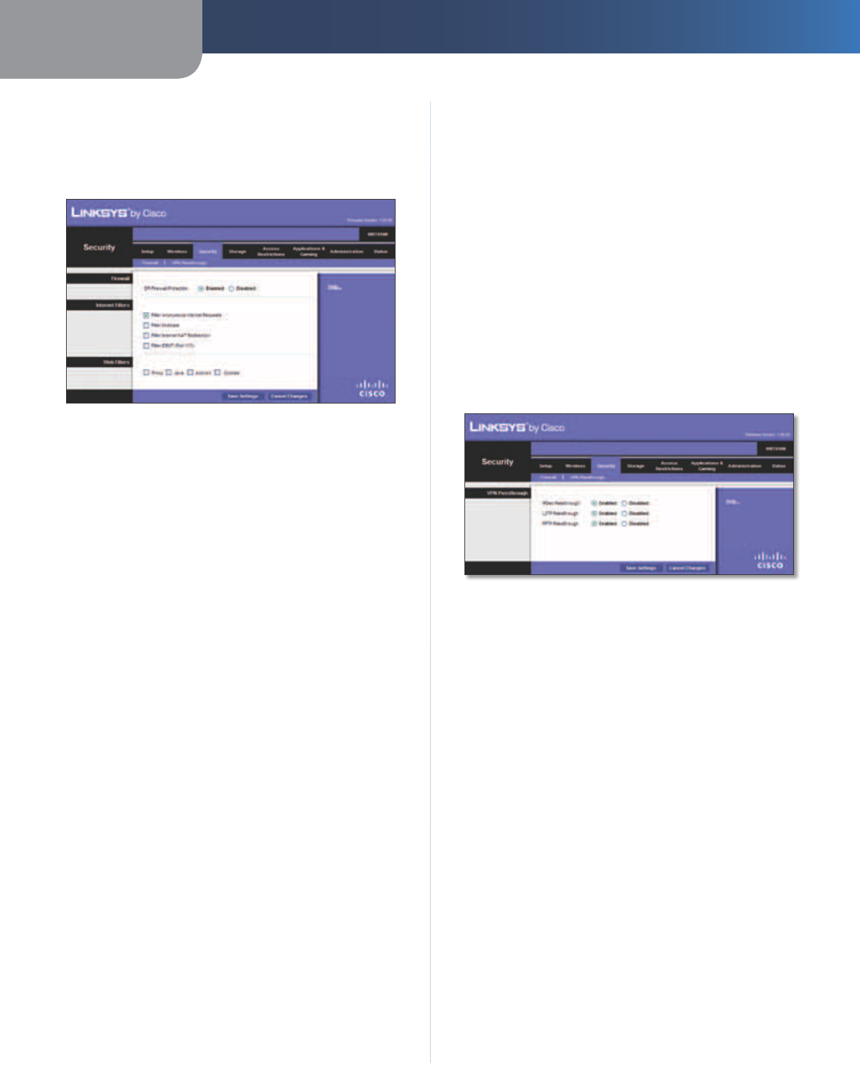
Security > Firewall
The Firewall screen is used to configure a firewall that can
filter out various types of unwanted traffic on the Router’s
local network.
Security > Firewall
Firewall
SPI Firewall Protection To use firewall protection,
keep the default selection, Enabled. To turn off firewall
protection, select Disabled.
Internet Filters
Filter Anonymous Internet Requests This feature
makes it more difficult for outside users to work their
way into your network. This option is enabled by default.
Disable it to allow anonymous Internet requests
.
Filter Multicast Multicasting allows for multiple
transmissions to specific recipients at the same time. If
multicasting is permitted, then the Router will allow IP
multicast packets to be forwarded to the appropriate
computers. Select this option to enable the filter.
Filter Internet NAT Redirection This feature is used to
prevent a local computer from using a URL or Internet
address to access the local server. Select this option to
enable the filter.
Filter IDENT (Port 113) This feature keeps port 113 from
being scanned by devices outside of your local network.
Select this option to enable the filter.
Web Filters
Proxy Use of WAN proxy servers may compromise the
Gateway’s security. Denying Proxy will disable access to
any WAN proxy servers. Select this option to enable proxy
filtering. Deselect the feature to allow proxy access.
Java Java is a programming language for websites. If you
deny Java, you run the risk of not having access to Internet
sites created using this programming language. Select
this option to enable Java filtering. Deselect the feature to
allow Java usage.
ActiveX ActiveX is a programming language for websites.
If you deny ActiveX, you run the risk of not having access to
Internet sites created using this programming language.
Select this option to enable ActiveX filtering. Deselect the
feature to allow ActiveX usage.
Cookies A cookie is data stored on your computer and
used by Internet sites when you interact with them. Select
this option to filter cookies. Deselect the feature to allow
cookie usage.
Click Save Settings to apply your changes, or click Cancel
Changes to clear your changes.
Security > VPN Passthrough
The VPN Passthrough screen allows you to enable VPN
tunnels using IPSec, L2TP, or PPTP protocols to pass through
the Router’s firewall.
Security > VPN Passthrough
VPN Passthrough
IPSec Passthrough Internet Protocol Security (IPSec) is
a suite of protocols used to implement secure exchange
of packets at the IP layer. To allow IPSec tunnels to pass
through the Router, keep the default, Enabled.
L2TP Passthrough Layer 2 Tunneling Protocol is the
method used to enable Point-to-Point sessions via the
Internet on the Layer 2 level. To allow L2TP tunnels to pass
through the Router, keep the default, Enabled.
PPTP Passthrough Point-to-Point Tunneling Protocol
(PPTP) allows the Point-to-Point Protocol (PPP) to be
tunneled through an IP network. To allow PPTP tunnels to
pass through the Router, keep the default, Enabled.
Click Save Settings to apply your changes, or click Cancel
Changes to clear your changes.
Chapter 3 Advanced Configuration
20
Simultaneous Dual-Band Wireless-N Gigabit Router
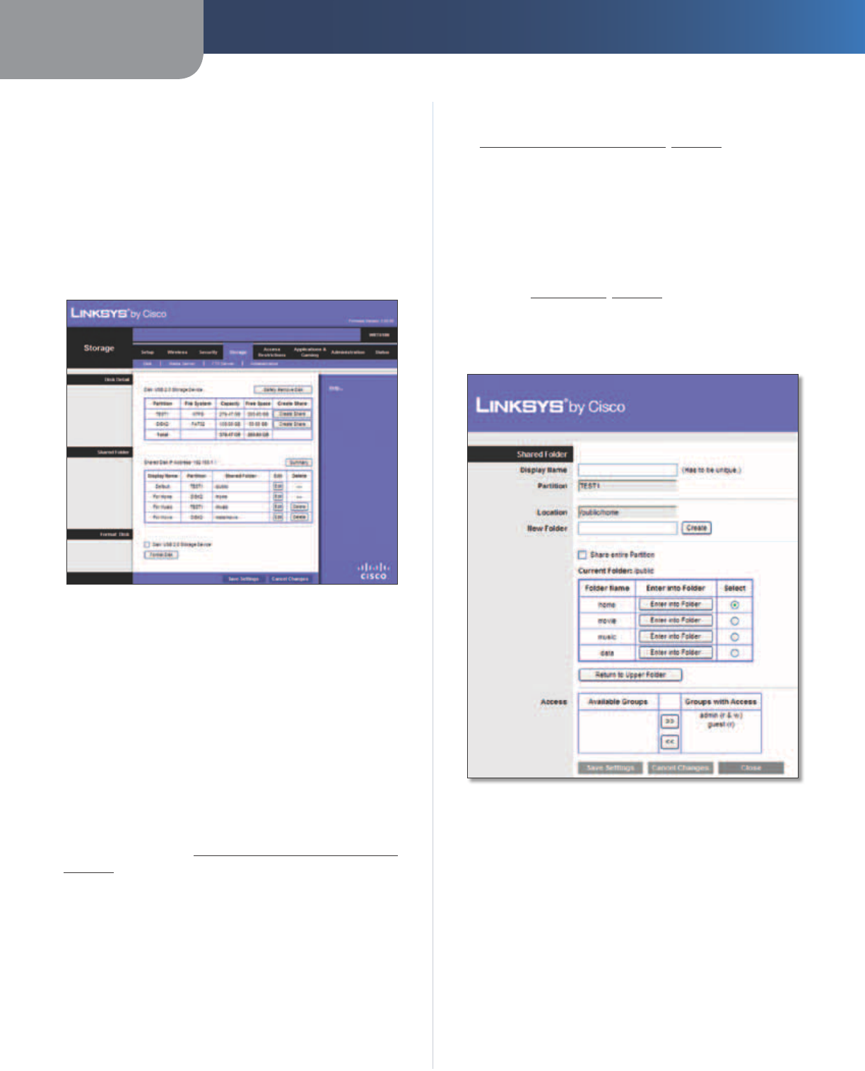
Storage > Disk
The storage options are available when a USB storage
device is connected to the USB port of the Router.
The Disk screen describes the disk currently attached to
the Router. Use this screen to create shared folders, safely
remove a disk, or format a disk (any data on the disk will
be deleted during formatting).
Shared folders are folders you create to manage access to
the folders on the disk.
Storage > Disk
Disk Detail
If a formatted disk is connected to the Router, then its name
is displayed. For each partition of the disk, the Partition,
File System, Capacity, and Free Space information are
displayed.
Safely Remove Disk Before physically disconnecting a
disk from the Router, click Safely Remove Disk first. This
prevents the possible loss of data, which may occur if you
remove the disk while it is transferring data.
Create Share To create a shared folder, click this option
for the appropriate partition, and the Shared Folder screen
appears. Proceed to Create or Edit a Shared Folder,
page 20.
Shared Folder
Shared Disk IP Address The IP address of the disk is
displayed.
Summary To view a list of shared folders, click this option.
For each shared folder, the Display Name, Partition, and
Shared Folder location are displayed.
Edit To change the access settings of a shared folder, click
this option, and the Shared Folder screen appears. Proceed
to Create or Edit a Shared Folder, page 20.
Delete To delete a shared folder, click this option.
Format Disk
Disk To format a disk and create a new partition, select
the disk you want to format, and then click Format Disk. (If
your disk was formatted with multiple partitions, then the
formatting will delete them and create a single partition.)
Proceed to Format Disk, page 21.
Create or Edit a Shared Folder
Use this screen to add a shared folder.
Shared Folder
Shared Folder
Display Name Create a name for the folder. This will
appear in the Shared Folder table on the Disk screen.
Partition The name of the partition is displayed.
Location The location of the folder is displayed.
New Folder Create a name for the physical location of
the folder. Then click Create.
Share entire Partition Select this option if the folder
should include the entire partition.
If you do not want to share the entire partition, then select
the folder you do want to share.
Chapter 3 Advanced Configuration
21
Simultaneous Dual-Band Wireless-N Gigabit Router
Current Folder The current folder is displayed.
Folder Name The available folders are listed by Folder
Name.
Enter into Folder To display sub-folders, click this button.
Select Select a folder.
Return to Upper Folder To return to the previous folder,
click this button.
Access
Specify which user groups have read-and-write or read-
only access to the folder. (To create user groups, refer to
Create or Edit a Group Account, page 24.)
Available Groups To allow a group access to the folder,
select it, and then click the >> button.
Groups with Access To block a group from accessing the
folder, select it, and then click the << button.
Click Save Settings to apply your changes, or click Can-
cel Changes to clear your changes. Click Close to exit the
screen.
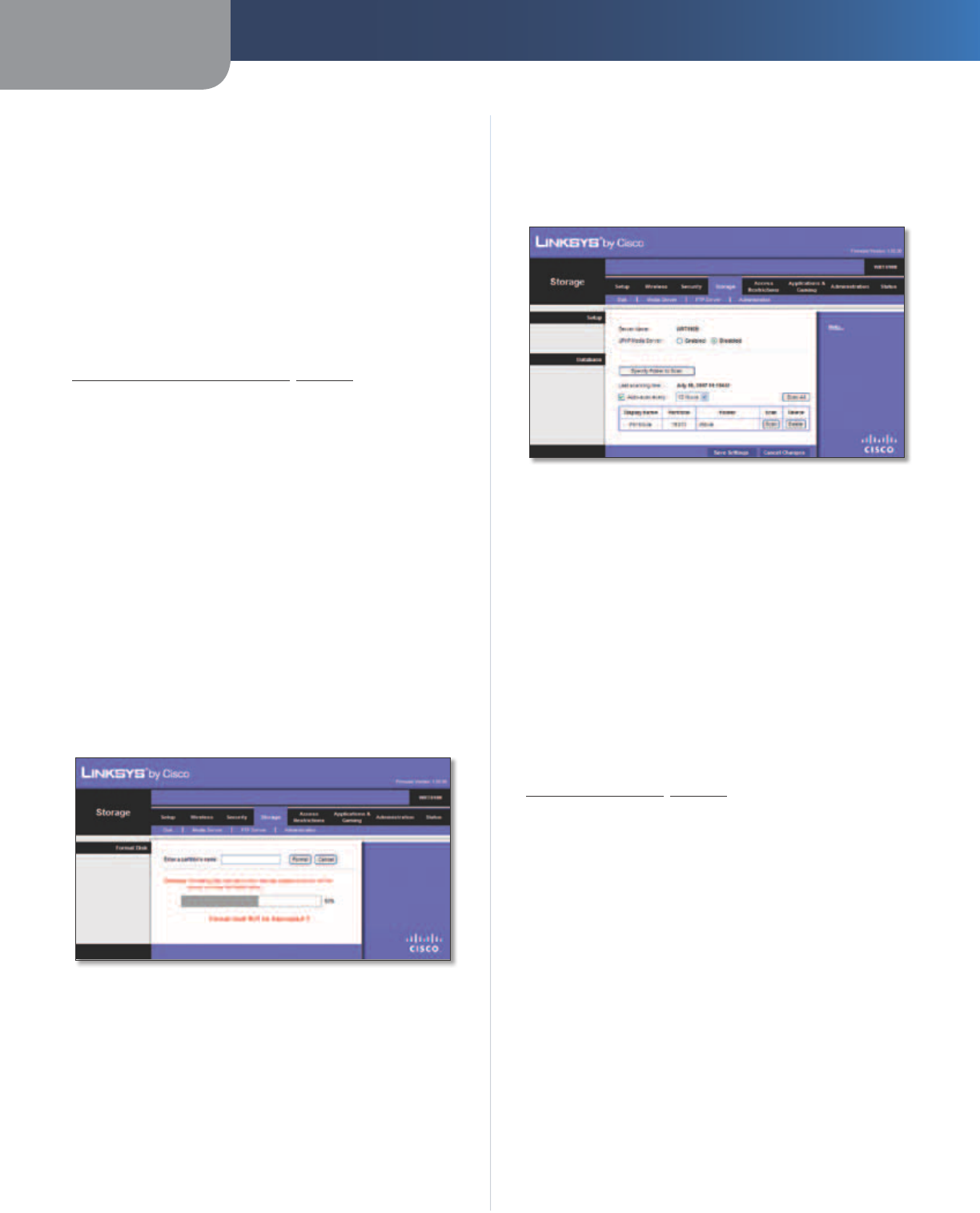
Format Disk
Enter a partition’s name Create a name for the partition.
(If your disk was formatted with multiple partitions,
then the formatting will delete them and create a single
partition.)
To format the disk as FAT32, click Format and follow the
on-screen instructions. To cancel the formatting, click
Cancel.
Format Disk
Storage > Media Server
The storage options are available when a USB storage
device is connected to the USB port of the Router.
If you have UPnP AV-enabled (or DLNA-certified) devices
in your home, then you can use the Router as a media
server. Examples of UPnP AV-enabled devices include a
digital media adapter, a gaming console with a built-in
media player, or a digital picture frame.
For example, if you have a digital media adapter that sends
content to your entertainment system, then the digital
media adapter can locate the Router using the UPnP AV
standard. The folders you specify can then be accessed
and played by the digital media adapter.
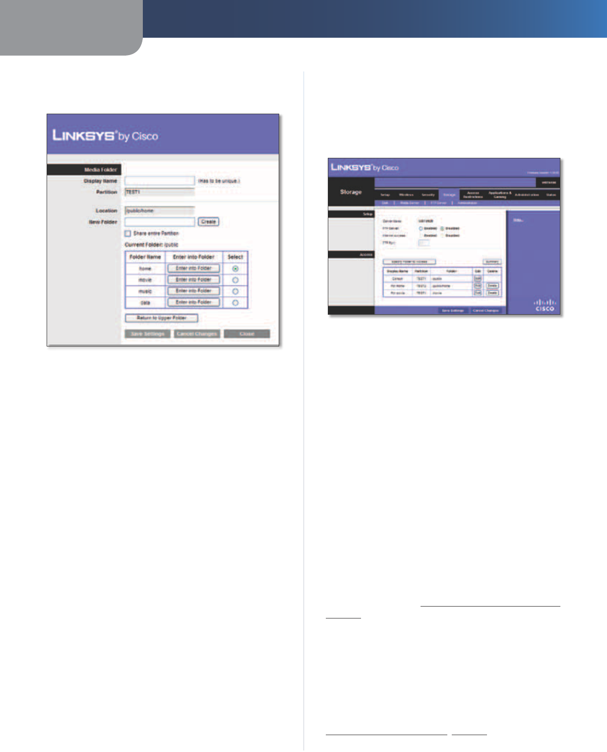
Storage > Media Server
Setup
Server Name The default server name of the Router is
WRT610N.
UPnP Media Server To use the Router’s media server
function, select Enabled. Otherwise, select Disabled.
Database
This section lets you select content to add to the database
of the Router’s media server.
Specify Folder to Scan To add a media folder to
the database of the Router’s media server, click this
button. The Media Folder screen appears. Proceed to
Add a Media Folder, page 22.
Last scanning time The last time the media server
scanned for content is displayed.
Auto-scan every __ To automatically scan the media
folders, select this option. Then select the appropriate
interval: 2 Hours (default), 6 Hours, 12 Hours, 24 Hours,
or 48 Hours.
Scan All To scan all media files, click this button.
The database table lists the media folders with the
following information: Display Name, Partition, and Folder.
Scan To scan a folder, click Scan.
Delete To delete a folder, click Delete.
Chapter 3 Advanced Configuration
22
Simultaneous Dual-Band Wireless-N Gigabit Router
Add a Media Folder
Use this screen to add a media folder.
Media Folder
Media Folder
Display Name Create a name for the folder. This will
appear in the Database table on the Media Server screen.
Partition The name of the partition is displayed.
Location The location of the folder is displayed.
New Folder Create a name for the physical location of
the folder. Then click Create.
Share entire Partition Select this option if the folder
should include the entire partition.
If you do not want to share the entire partition, then select
the folder you do want to share.
Current Folder The current folder is displayed.
Folder Name The available folders are listed by Folder
Name.
Enter into Folder To display sub-folders, click this button.
Select Select a folder.
Return to Upper Folder To return to the previous folder,
click this button.
Click Save Settings to apply your changes, or click Cancel
Changes to clear your changes. Click Close to exit the
screen.
On the Media Server screen, click Save Settings to apply
your changes, or click Cancel Changes to clear your
changes.
Storage > FTP Server
The storage options are available when a USB storage
device is connected to the USB port of the Router.
The FTP Server tab creates an FTP server that can be
accessed from the Internet or your local network.
Storage> FTP Server
Setup
Server Name The default server name of the Router is
WRT610N.
FTP Server Select Enabled to use the Router as an FTP
server. Otherwise, select Disabled. An external USB hard
drive or USB disk must be connected to the USB port to
use this service.
Internet Access Select Enabled to allow access of the
FTP server from the Internet. Otherwise, select Disabled
to only allow local network access.
FTP Port Enter the FTP Port number to use. The default
is 21.
Access
This section lets you add FTP folders that can be accessed
through the FTP client.
Specify Folder to Access To add an FTP folder to the
Access table, click this button. The FTP Folder screen
appears. Proceed to Create or Edit an FTP Folder,
page 23.
Summary To view a list of FTP folders, click this option.
For each FTP folder, the Display Name, Partition, and
Folder location are displayed.
The database table lists the FTP folders with the following
information: Display Name, Partition, and Folder.
Edit To change the access settings of an FTP folder, click
this option, and the FTP Folder screen appears. Proceed to
Create or Edit an FTP Folder, page 23.
Chapter 3 Advanced Configuration
23
Simultaneous Dual-Band Wireless-N Gigabit Router
Delete To delete an FTP folder, click this option.
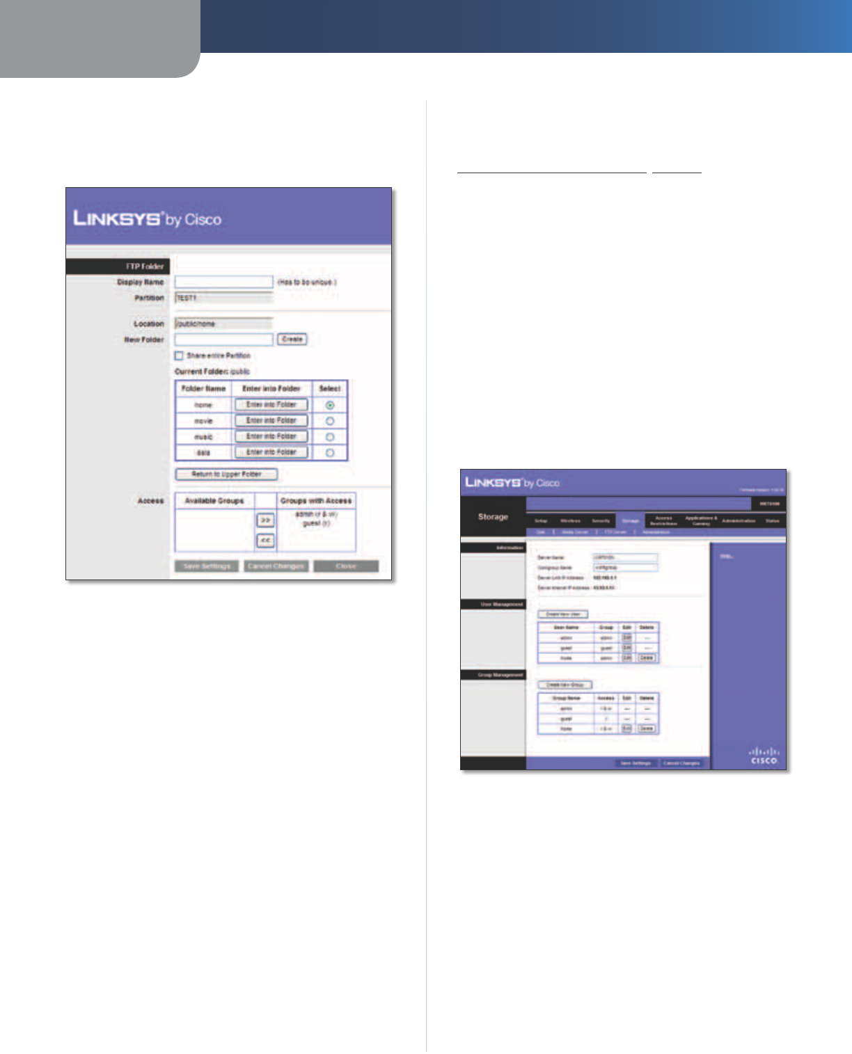
Create or Edit an FTP Folder
Use this screen to add an FTP folder.
FTP Folder Screen
Display Name Create a name for the folder. Enter a
display name that will appear in the Access table of the
FTP Server screen.
Partition The name of the partition is displayed.
Location The location of the folder is displayed.
New Folder Create a name for the physical location of
the folder. Then click Create.
Share entire Partition Select this option if the folder
should include the entire partition.
If you do not want to share the entire partition, then select
the folder you do want to share.
Current Folder The current folder is displayed.
Folder The available folders are listed by Folder name.
Enter into Folder To display sub-folders, click this button.
Select Select a folder.
Return to Upper Folder To return to the previous folder,
click this button.
Access
Specify which user groups have read-and-write or read-
only access to the folder. (To create user groups, refer to
Create or Edit a Group Account, page 24.)
Available Groups To allow a group access to the folder,
select it, and then click the >> button.
Groups with Access To block a group from accessing the
folder, select it, and then click the << button.
Click Save Settings to apply your changes, or click Cancel
Changes to clear your changes. Click Close to exit the
screen.
On the FTP Server screen, click Save Settings to apply your
changes, or click Cancel Changes to clear your changes.
Storage > Administration
The Administration screen allows you to manage the user
groups and individual users who can access the shared
folders.
Storage > Administration
Information
Server Name The default server name of the Router is
WRT610N.
Workgroup Name Enter the workgroup name for the
Router; it should match the workgroup name of the
computers on your local network. The Router’s default is
workgroup.
Server LAN IP Address The local IP address of the
Router’s media and FTP server is displayed.
Server Internet IP Address The Internet IP address of
the Router’s FTP server is displayed.
Chapter 3 Advanced Configuration
24
Simultaneous Dual-Band Wireless-N Gigabit Router
User Management
By default the Router creates two users, admin and guest.
The users are listed by User Name and Group.
Create New User To create a new user, click this
button. The User Account screen appears. Proceed to
Create or Edit a User Account, page 24.
Edit To change the settings of a user account, click
Edit, and the User Account screen appears. Proceed to
Create or Edit a User Account, page 24.
Delete To delete a user, click this button.
Group Management
By default the Router creates two user groups, admin and
guest.
The groups are listed by Group Name and Access level.
There are two levels of access, r & w (read-and-write) and
r (read-only).
Create New Group To create a new group of users, click
this button. The Group Account screen appears. Proceed to
Create or Edit a Group Account, page 24.
Edit To change the description or access rights of a group,
click Edit, and the Group Account screen appears. Proceed
to Create or Edit a Group Account, page 24.
Delete To delete a group, click this button.
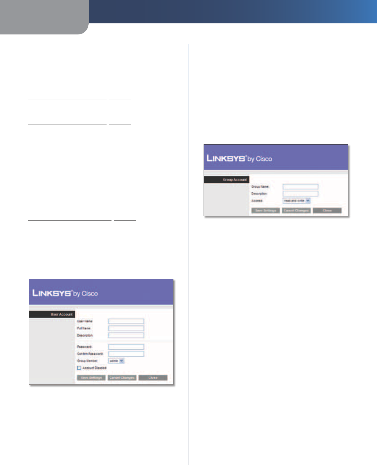
Create or Edit a User Account
User Account
User Account
User Name Create a name for the user.
Full Name Enter the actual name of the user.
Description Enter keywords to describe the user.
Password Enter the password that the user will use for
login
Confirm Password Enter the password again to confirm.
Group Member Select the appropriate user group.
Account Disabled To temporarily disable an account,
select this option.
Click Save Settings to apply your changes, or click Cancel
to clear your changes. Click Close to exit the screen.
On the Administration screen, click Save Settings to
apply your changes, or click Cancel Changes to clear your
changes.
Create or Edit a Group Account
Group Account
Group Account
Group Name Create a name for the group.
Description Enter keywords to describe the group.
Access Select the appropriate level of access, read and
write or read only.
Click Save Settings to apply your changes, or click Cancel
to clear your changes. Click Close to exit the screen.
On the Administration screen, click Save Settings to
apply your changes, or click Cancel Changes to clear your
changes.
Chapter 3 Advanced Configuration
25
Simultaneous Dual-Band Wireless-N Gigabit Router
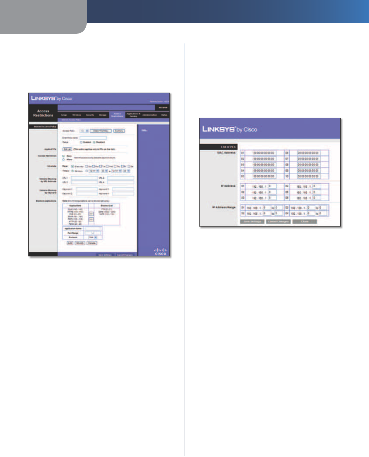
Access Restrictions > Internet Access
The Internet Access screen allows you to deny or allow
specific kinds of Internet usage and traffic, such as Internet
access, designated services, and websites during specific
days and times.
Access Restrictions > Internet Access
Internet Access Policy
Access Policy Access can be managed by a policy. Use
the settings on this screen to establish an access policy
(after Save Settings is clicked). Selecting a policy from
the drop-down menu will display that policy’s settings.
To delete a policy, select that policy’s number and click
Delete This Policy. To view all the policies, click Summary.
Summary
The policies are listed with the following information: No.,
Policy Name, Access, Days, Time, and status (Enabled). To
enable a policy, select Enabled. To delete a policy, click
Delete. Click Save Settings to save your changes, or click
Cancel Changes to clear your changes. To return to the
Internet Access Policy screen, click Close.
Status Policies are disabled by default. To enable a policy,
select the policy number from the drop-down menu, and
select Enabled.
To create a policy, follow steps 1-11. Repeat these steps to
create additional policies, one at a time.
1. Select a number from the Access Policy drop-down
menu.
2. Enter a Policy Name in the field provided.
3. To enable this policy, select Enabled.
4. Click Edit List to select which PCs will be affected by the
policy. The List of PCs screen appears. You can select a PC
by MAC address or IP address. You can also enter a range
of IP addresses if you want this policy to affect a group
of PCs. After making your changes, click Save Settings
to apply your changes, or click Cancel Changes to clear
your changes. Then click Close.
List of PCs
5. Select the appropriate option, Deny or Allow,
depending on whether you want to block or allow
Internet access for the PCs you listed on the List of PCs
screen.
6. Decide which days and what times you want this
policy to be enforced. Select the individual days during
which the policy will be in effect, or select Everyday.
Then enter a range of hours and minutes during which
the policy will be in effect, or select 24 Hours.
7. You can block websites with specific URL addresses.
Enter each URL in a separate Website Blocking by URL
Address field.
8. You can also block websites using specific keywords.
Enter each keyword in a separate Website Blocking by
Keyword field.
9. You can filter access to various services accessed
over the Internet, such as FTP or telnet. (You
can block up to three applications per policy.)
From the Applications list, select the application you
want to block. Then click the >> button to move it to
the Blocked List. To remove an application from the
Blocked List, select it and click the << button.
10. If the application you want to block is not listed or you
want to edit a service’s settings, enter the application’s
name in the Application Name field. Enter its range
in the Port Range fields. Select its protocol from the
Protocol drop-down menu. Then click Add.
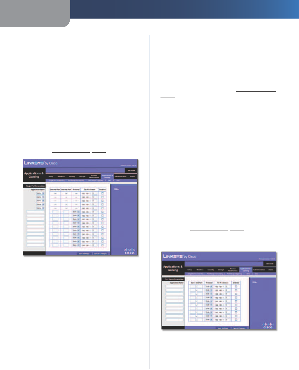
Chapter 3 Advanced Configuration
26
Simultaneous Dual-Band Wireless-N Gigabit Router
To modify a service, select it from the Application list.
Change its name, port range, and/or protocol setting.
Then click Modify.
To delete a service, select it from the Application list.
Then click Delete.
11. Click Save Settings to save the policy’s settings, or
click Cancel Changes to clear the changes.
Applications and Gaming > Single Port
Forwarding
The Single Port Forwarding screen allows you to customize
port services for common applications.
When users send these types of requests to your network via
the Internet, the Router will forward those requests to the
appropriate servers (computers). Before using forwarding,
you should assign static IP addresses to the designated
servers (use the DHCP Reservation feature on the Basic Setup
screen; refer to DHCP Reservation, page 9).
Applications and Gaming > Single Port Forwarding
Single Port Forwarding
Common applications are available for the first five entries.
Application Name Select the appropriate application.
To IP Address Enter the IP address of the server that
should receive these requests.
Enabled For each application, select Enabled to activate
port forwarding.
For additional applications, complete the following fields:
Application Name Enter the name you wish to give the
application. Each name can have up to 12 characters.
External Port Enter the external port number used by
the server or Internet application. Check with the Internet
application documentation for more information.
Internal Port Enter the internal port number used by
the server or Internet application. Check with the Internet
application documentation for more information.
Protocol Select the protocol(s) used for this application,
TCP, UDP, or Both.
To IP Address For each application, enter the IP address
of the computer that should receive the requests. If you
assigned a static IP address to the computer, then you can
look up its static IP address; refer to DHCP Reservation,
page 9.
Enabled For each application, select Enabled to enable
port forwarding.
Click Save Settings to apply your changes, or click Cancel
Changes to clear your changes.
Applications and Gaming > Port Range
Forwarding
The Port Range Forwarding screen allows you to set up
public services on your network, such as web servers,
ftp servers, e-mail servers, or other specialized Internet
applications. (Specialized Internet applications are any
applications that use Internet access to perform functions
such as videoconferencing or online gaming. Some Internet
applications may not require any forwarding.)
When users send these types of requests to your network via
the Internet, the Router will forward those requests to the
appropriate servers (computers). Before using forwarding,
you should assign static IP addresses to the designated
servers (use the DHCP Reservation feature on the Basic Setup
screen; refer to DHCP Reservation, page 9).
If you need to forward all ports to one computer, click the
DMZ tab.
Applications and Gaming > Port Range Forwarding
Port Range Forwarding
To forward a port, enter the information on each line for
the criteria required.
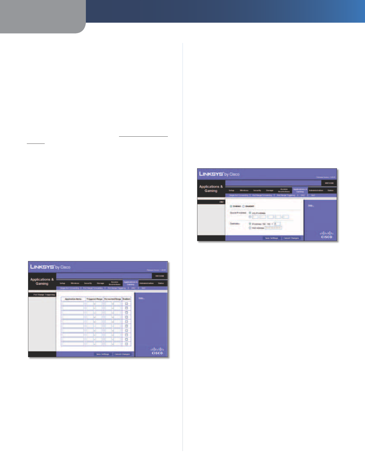
Chapter 3 Advanced Configuration
27
Simultaneous Dual-Band Wireless-N Gigabit Router
Application Name In this field, enter the name you
wish to give the application. Each name can be up to 12
characters.
Start~End Port Enter the number or range of port(s)
used by the server or Internet applications. Check with the
Internet application documentation for more information.
Protocol Select the protocol(s) used for this application,
TCP, UDP, or Both.
To IP Address For each application, enter the IP address
of the computer running the specific application. If you
assigned a static IP address to the computer, then you can
look up its static IP address; refer to DHCP Reservation,
page 9.
Enabled Select Enabled to enable port forwarding.
Click Save Settings to apply your changes, or click Cancel
Changes to clear your changes.
Applications & Gaming > Port Range
Triggering
The Port Range Triggering screen allows the Router to
watch outgoing data for specific port numbers. The IP
address of the computer that sends the matching data is
remembered by the Router, so that when the requested
data returns through the Router, the data is pulled back
to the proper computer by way of IP address and port
mapping rules.
Applications and Gaming > Port Range Triggering
Port Range Triggering
Application Name Enter the application name of the
trigger.
Triggered Range For each application, enter the starting
and ending port numbers of the triggered port number
range. Check with the Internet application documentation
for the port number(s) needed.
Forwarded Range For each application, enter the
starting and ending port numbers of the forwarded
port number range. Check with the Internet application
documentation for the port number(s) needed.
Enabled Select Enabled to enable port triggering.
Click Save Settings to apply your changes, or click Cancel
Changes to clear your changes.
Applications and Gaming > DMZ
The DMZ feature allows one network computer to be
exposed to the Internet for use of a special-purpose
service such as Internet gaming or videoconferencing.
DMZ hosting forwards all the ports at the same time to
one PC. The Port Range Forwarding feature is more secure
because it only opens the ports you want to have opened,
while DMZ hosting opens all the ports of one computer,
exposing the computer to the Internet.
Applications and Gaming > DMZ
DMZ
Any computer whose port is being forwarded should have
its DHCP client function disabled and have a new static IP
address assigned to it because its IP address may change
when using the DHCP function.
Enabled/Disabled To disable DMZ hosting, select
Disabled. To expose one PC, select Enabled. Then
configure the following settings:
Source IP Address If you want any IP address to be the
source, select Any IP Address. If you want to specify an IP
address or range of IP addresses as the designated source,
select and complete the IP address range fields.
Destination If you want to specify the DMZ host by IP
address, select IP Address and enter the IP address in the
field provided. If you want to specify the DMZ host by MAC
address, select MAC Address and enter the MAC address
in the field provided.
Click Save Settings to apply your changes, or click Cancel
Changes to clear your changes.