LINKSYS WRV200 Wireless-G VPN Router with RangeBooster User Manual The Router s Functions
LINKSYS LLC Wireless-G VPN Router with RangeBooster The Router s Functions
UserManual.wiki
>
LINKSYS
>
WRV200 User Manual
Manual
Navigation menu
Upload a User Manual
Namespaces
Wiki Guide
HTML
PDF
Info
Views
User Manual
Discussion / Help
Navigation
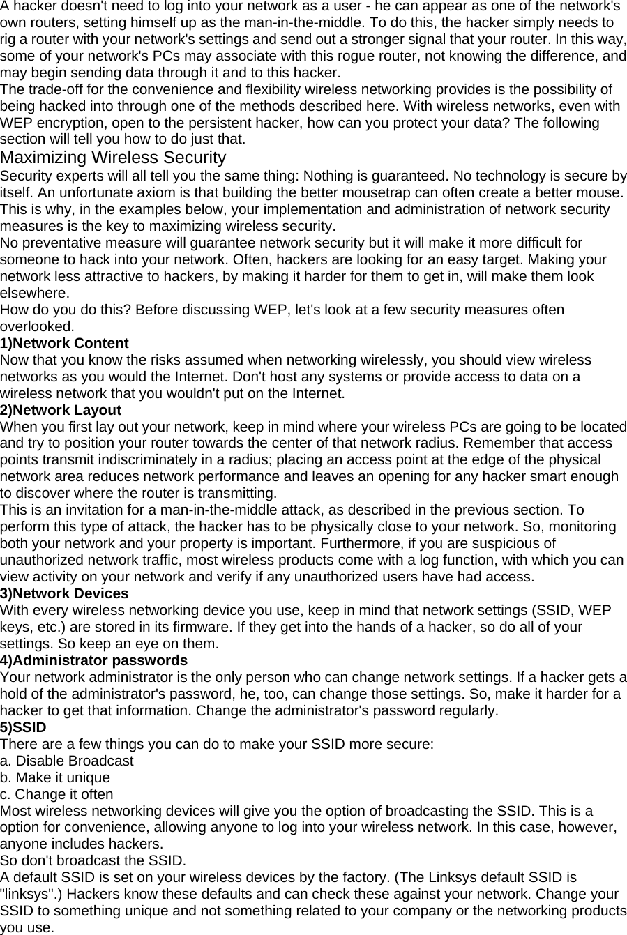
![this single address provided by the ISP. Does the Router support any operating system other than Windows 95, Windows 98SE, Windows Millennium, Windows 2000, or Windows XP? Yes, but Linksys does not, at this time, provide technical support for setup, configuration or troubleshooting of any non-Windows operating systems. Does the Router support ICQ send file? Yes, with the following fix: click ICQ menu -> preference -> connections tab->, and check I am behind a firewall or proxy. Then set the firewall time-out to 80 seconds in the firewall setting. The Internet user can then send a file to a user behind the Router. I set up an Unreal Tournament Server, but others on the LAN cannot join. What do I need to do? If you have a dedicated Unreal Tournament server running, you need to create a static IP for each of the LAN computers and forward ports 7777, 7778, 7779, 7780, 7781, and 27900 to the IP address of the server. You can also use a port forwarding range of 7777 ~ 27900. If you want to use the UT Server Admin, forward another port. (Port 8080 usually works well but is used for remote admin. You may have to disable this.) Then in the [UWeb.WebServer] section of the server.ini file, set the ListenPort to 8080 (to match the mapped port above) and ServerName to the IP assigned to the Router from your ISP. Can multiple gamers on the LAN get on one game server and play simultaneously with just one public IPaddress? It depends on which network game or what kind of game server you are using. For example, Unreal Tournament supports multi-login with one public IP. How do I get Half-Life: Team Fortress to work with the Router? The default client port for Half-Life is 27005. The computers on your LAN need to have “+clientport 2700x” added to the HL shortcut command line; the x would be 6, 7, 8, and on up. This lets multiple computers connect to the same server. One problem: Version 1.0.1.6 won’t let multiple computers with the same CD key connect at the same time, even if on the same LAN (not a problem with 1.0.1.3). As far as hosting games, the HL server does not need to be in the DMZ. Just forward port 27015 to the local IP address of the server computer. How can I block corrupted FTP downloads? If you are experiencing corrupted files when you download a file with your FTP client, try using another FTP program. The web page hangs; downloads are corrupt, or nothing but junk characters are being displayed on the screen. What do I need to do? Force your Ethernet adapter to 10Mbps or half duplex mode, and turn off the “Auto-negotiate” feature of your Ethernet adapter as a temporary measure. (Please look at the Network Control Panel in your Ethernet adapter’s Advanced Properties tab.) Make sure that your proxy setting is disabled in the browser. Check our website at www.linksys.com for more information. If all else fails in the installation, what can I do? Reset the Router by holding down the reset button until the Power LED fully turns on and off. Reset your cable or DSL modem by powering the unit off and then on. Obtain and flash the latest firmware release that is readily available on the Linksys website, www.linksys.com. How will I be notified of new Router firmware upgrades? All Linksys firmware upgrades are posted on the Linksys website at www.linksys.com, where they can be downloaded for free. To upgrade the Router’s firmware, use the System tab of the Router’s web-based utility. If the Router’s Internet connection is working well, there is no need to download a newer firmware version, unless that version contains new features that you would like to use. Downloading a more current version of Router firmware will not enhance the quality or speed of your Internet connection, and may disrupt your current connection stability. Will the Router function in a Macintosh environment? Yes, but the Router’s setup pages are accessible only through Internet Explorer 4.0 or Netscape Navigator 4.0 or higher for Macintosh. I am not able to get the web configuration screen for the Router. What can I do? You may have to remove the proxy settings on your Internet browser, e.g., Netscape Navigator or Internet Explorer. Or remove the dial-up settings on your browser. Check with your browser](https://usermanual.wiki/LINKSYS/WRV200/User-Guide-643293-Page-45.png)