LINKSYS WRV210 Wireless-G VPN Router with RangeBooster User Manual Book
LINKSYS LLC Wireless-G VPN Router with RangeBooster Book
UserManual.wiki
>
LINKSYS
>
WRV210 User Manual
>
Manual 1
Contents
1.
Manual 1
2.
Manual 2
Manual 1
Navigation menu
Upload a User Manual
Namespaces
Wiki Guide
HTML
PDF
Info
Views
User Manual
Discussion / Help
Navigation
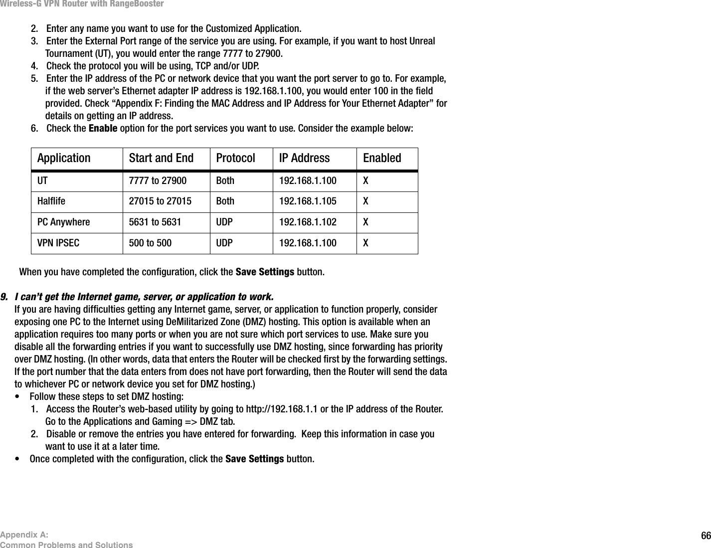
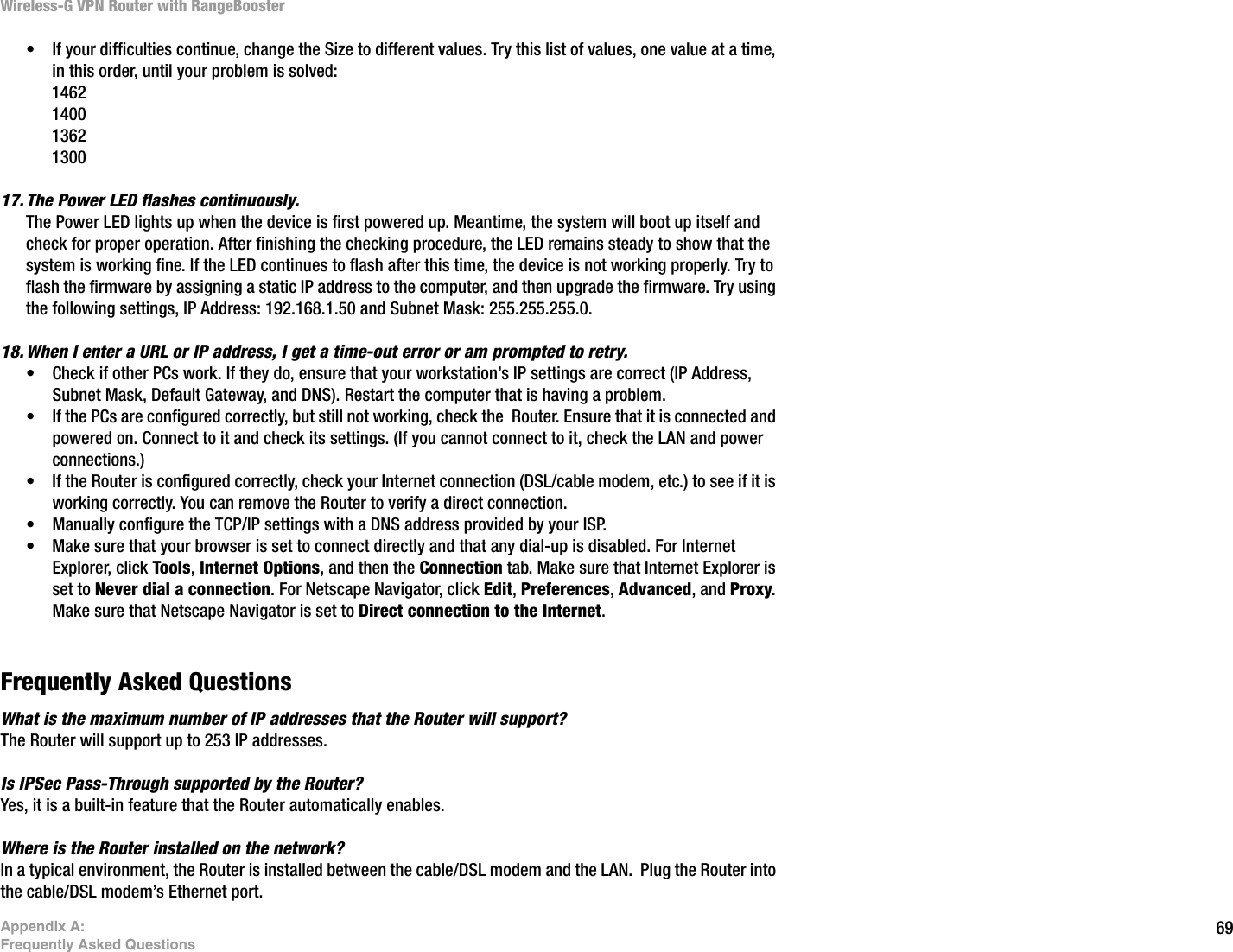
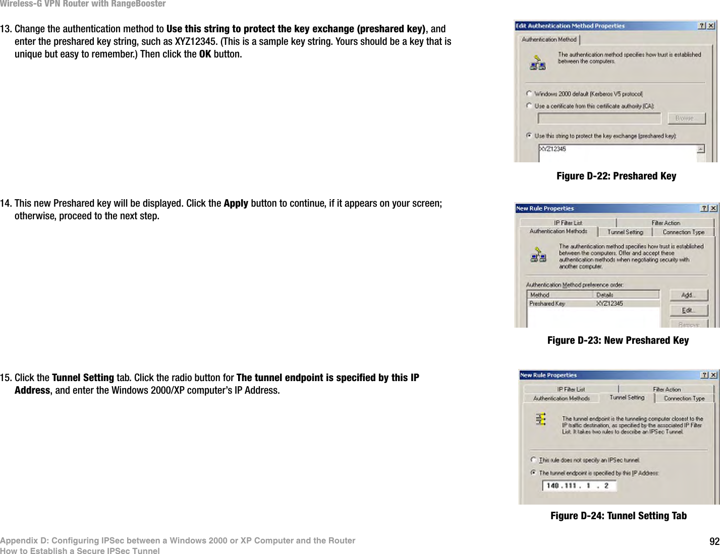
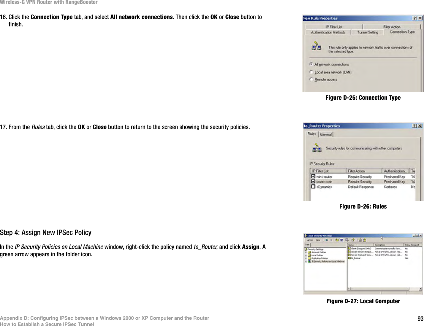
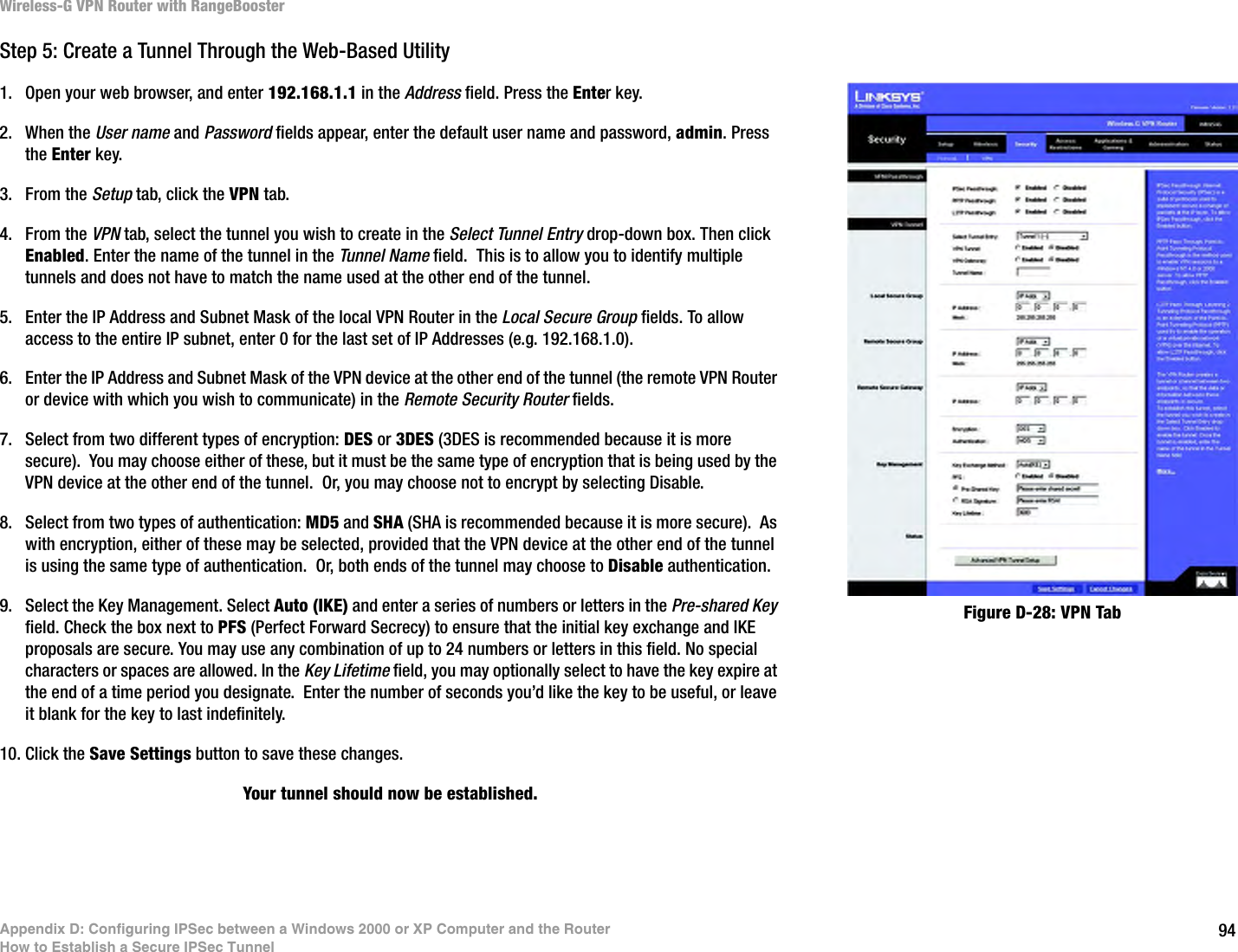
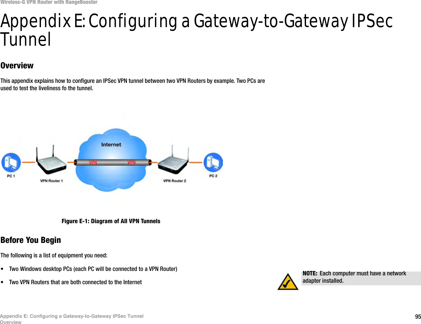
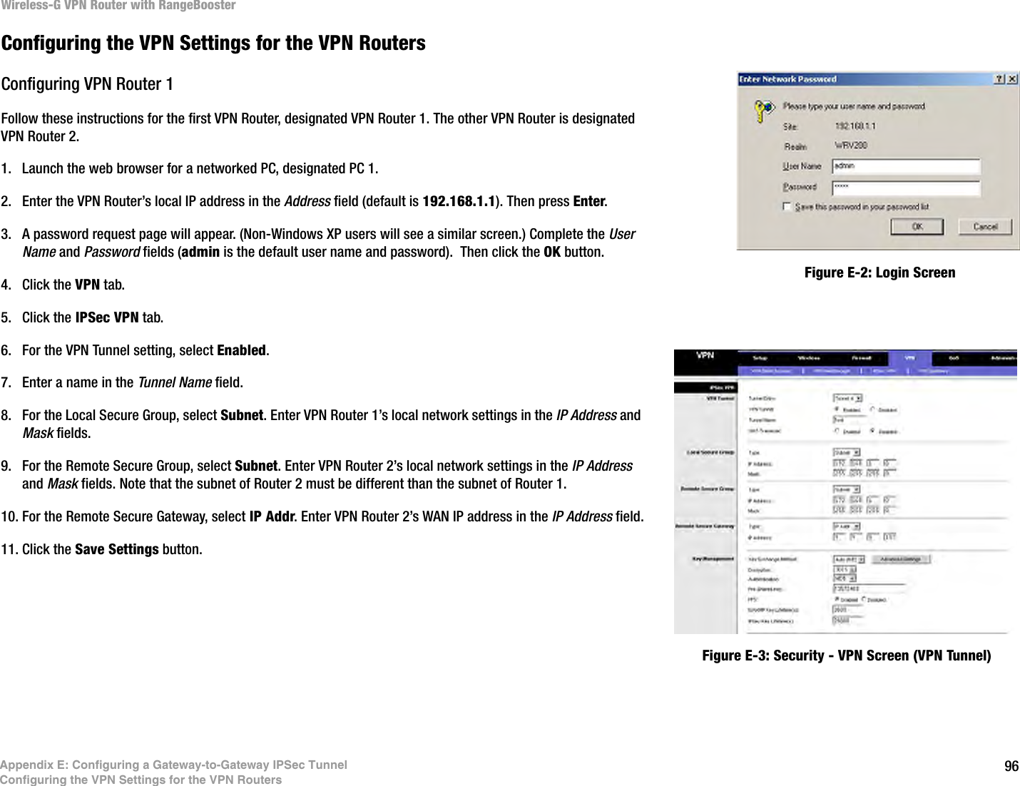
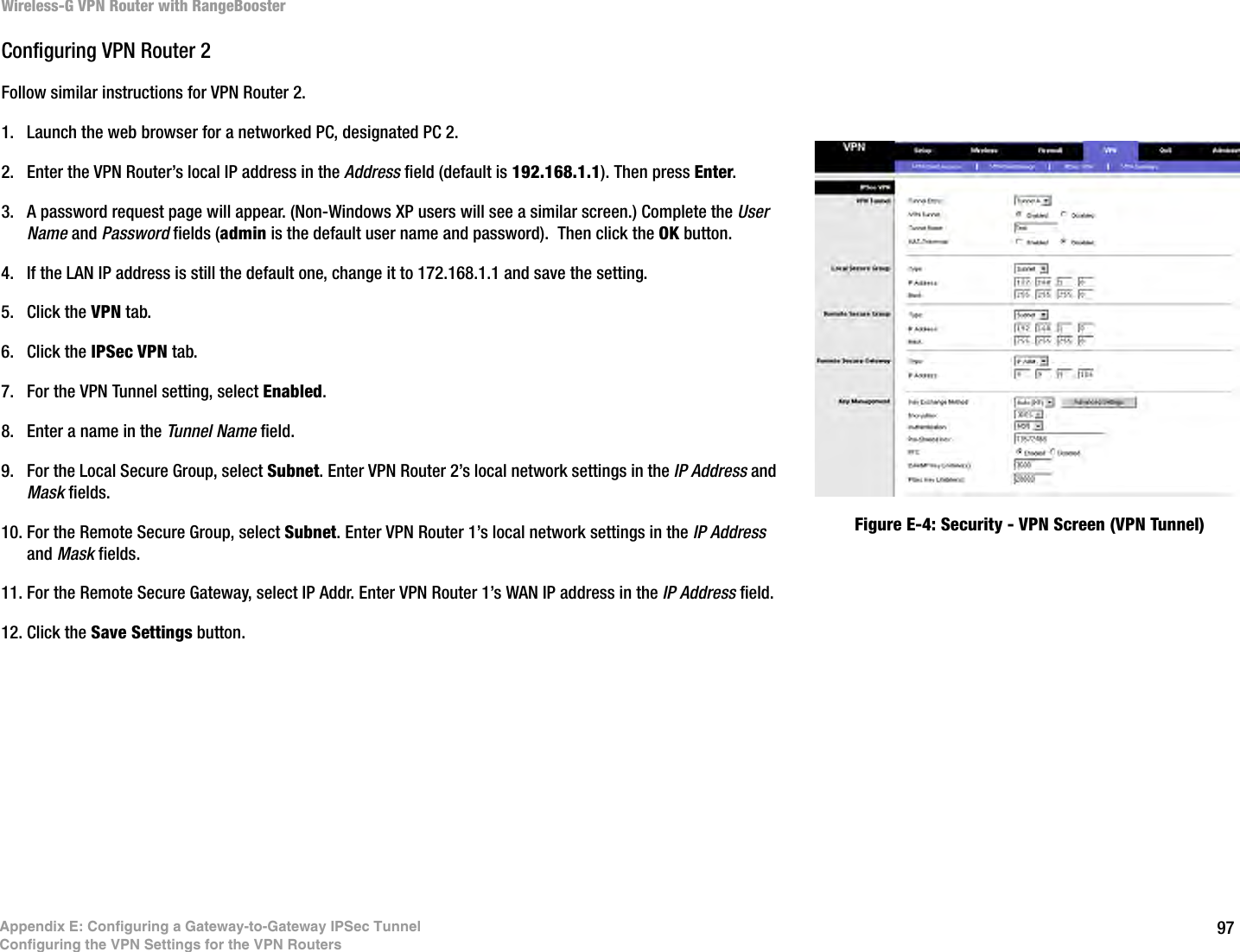
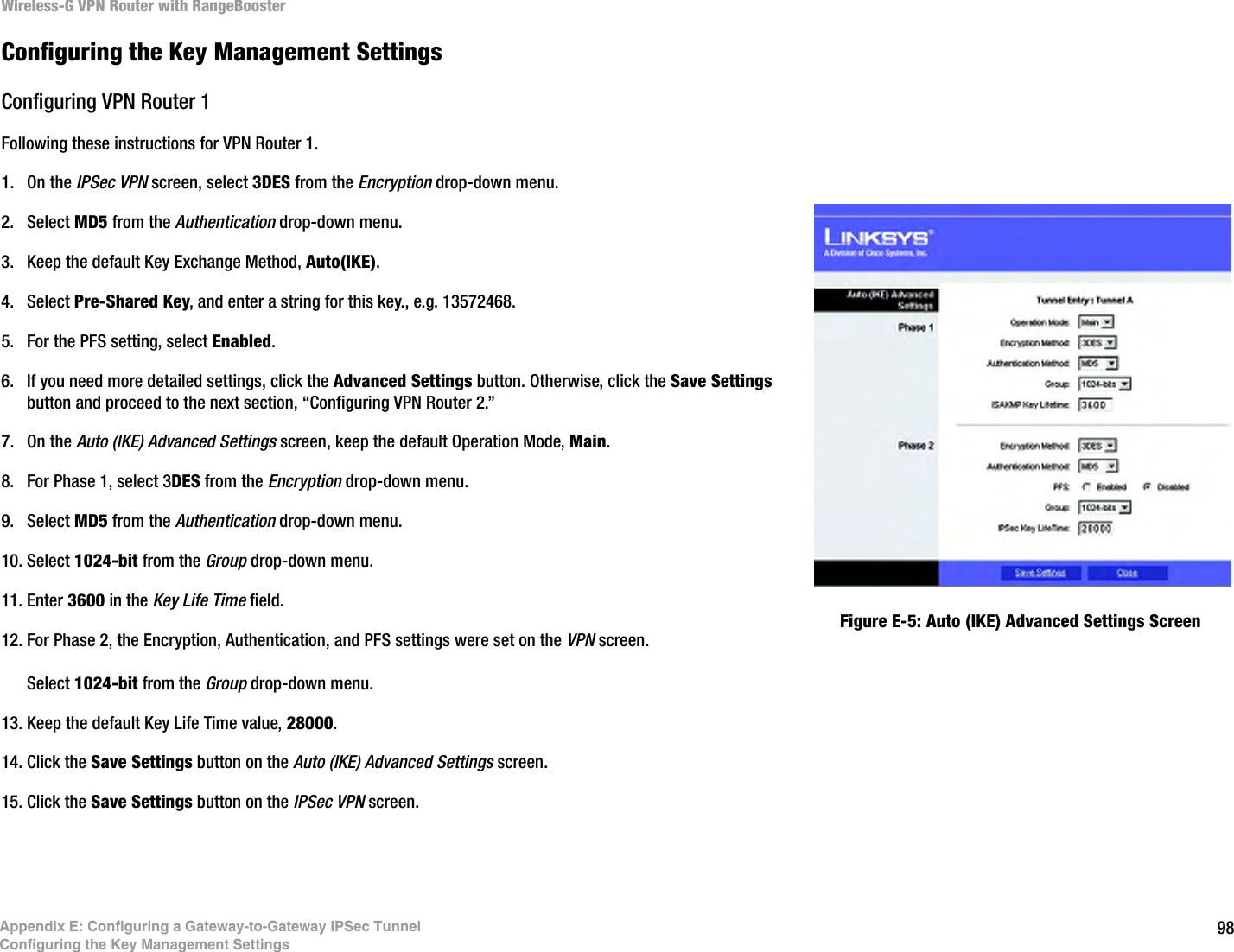
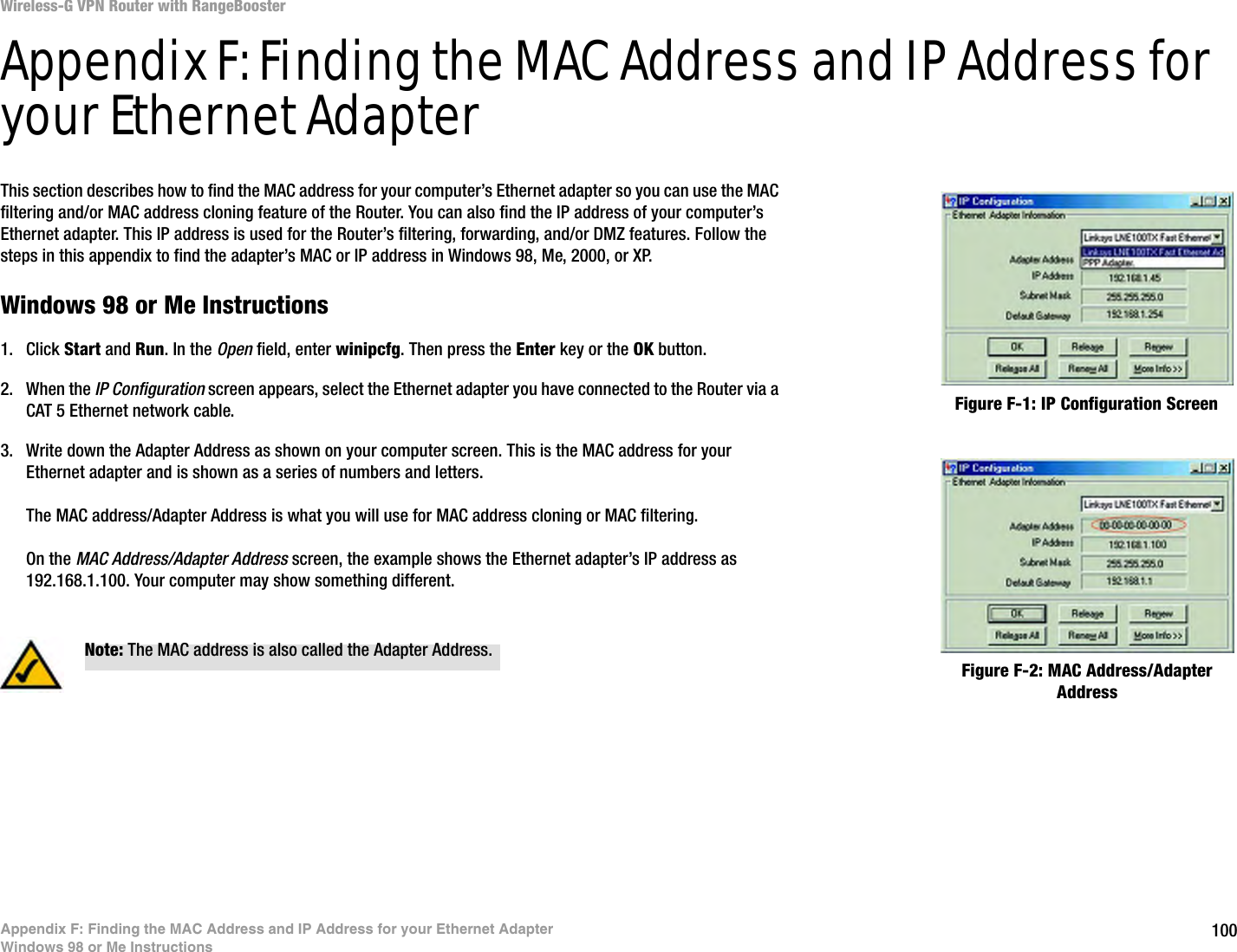
![70Appendix A: Frequently Asked QuestionsWireless-G VPN Router with RangeBoosterDoes the Router support IPX or AppleTalk? No. TCP/IP is the only protocol standard for the Internet and has become the global standard for communications. IPX, a NetWare communications protocol used only to route messages from one node to another, and AppleTalk, a communications protocol used on Apple and Macintosh networks, can be used for LAN to LAN connections, but those protocols cannot connect from the Internet to a LAN.Does the Internet connection of the Router support 100Mbps Ethernet? The Router’s current hardware design supports up to 100Mbps Ethernet on its Internet port; however, the Internet connection speed will vary depending on the speed of your broadband connection. The Router also supports 100Mbps over the auto-sensing Fast Ethernet 10/100 switch on the LAN side of the Router. What is Network Address Translation and what is it used for? Network Address Translation (NAT) translates multiple IP addresses on the private LAN to one public address that is sent out to the Internet. This adds a level of security since the address of a PC connected to the private LAN is never transmitted on the Internet. Furthermore, NAT allows the Router to be used with low cost Internet accounts, such as DSL or cable modems, when only one TCP/IP address is provided by the ISP. The user may have many private addresses behind this single address provided by the ISP.Does the Router support any operating system other than Windows 95, Windows 98SE, Windows Millennium, Windows 2000, or Windows XP? Yes, but Linksys does not, at this time, provide technical support for setup, configuration or troubleshooting of any non-Windows operating systems.Does the Router support ICQ send file? Yes, with the following fix: click ICQ menu -> preference -> connections tab->, and check I am behind a firewall or proxy. Then set the firewall time-out to 80 seconds in the firewall setting. The Internet user can then send a file to a user behind the Router.I set up an Unreal Tournament Server, but others on the LAN cannot join. What do I need to do? If you have a dedicated Unreal Tournament server running, you need to create a static IP for each of the LAN computers and forward ports 7777, 7778, 7779, 7780, 7781, and 27900 to the IP address of the server. You can also use a port forwarding range of 7777 ~ 27900. If you want to use the UT Server Admin, forward another port. (Port 8080 usually works well but is used for remote admin. You may have to disable this.) Then in the [UWeb.WebServer] section of the server.ini file, set the ListenPort to 8080 (to match the mapped port above) and ServerName to the IP assigned to the Router from your ISP.Can multiple gamers on the LAN get on one game server and play simultaneously with just one public IP address? It depends on which network game or what kind of game server you are using. For example, Unreal Tournament supports multi-login with one public IP.](https://usermanual.wiki/LINKSYS/WRV210.Manual-1/User-Guide-856340-Page-80.png)