LINKSYS WRVS4400NV11 Wireless-N Gigabit Security Router with VPN User Manual Book
LINKSYS LLC Wireless-N Gigabit Security Router with VPN Book
UserManual.wiki
>
LINKSYS
>
WRVS4400NV11 User Manual
>
Manual 1
Contents
1.
Manual 1
2.
Manual 2
Manual 1
Navigation menu
Upload a User Manual
Namespaces
Wiki Guide
HTML
PDF
Info
Views
User Manual
Discussion / Help
Navigation


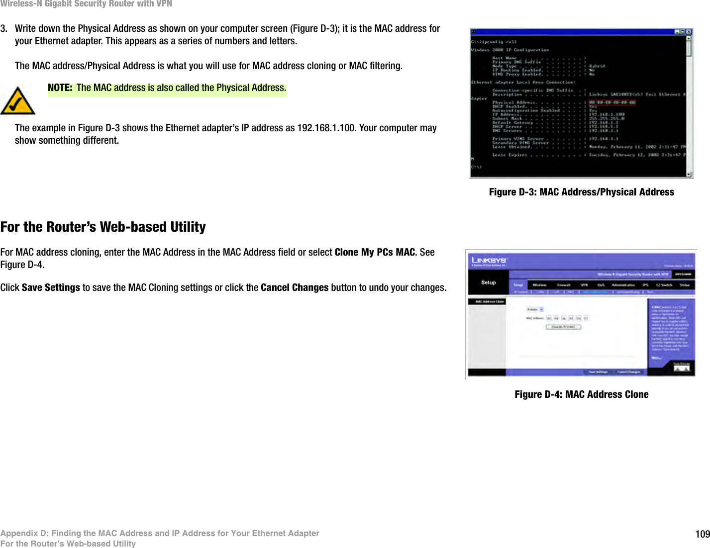
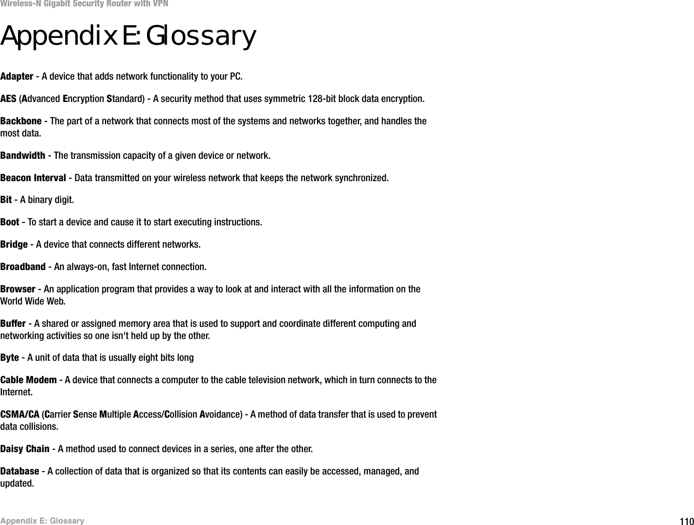
![96Appendix A: TroubleshootingFrequently Asked QuestionsWireless-N Gigabit Security Router with VPNWhat is Network Address Translation and what is it used for?Network Address Translation (NAT) translates multiple IP addresses on the private LAN to one public address that is sent out to the Internet. This adds a level of security since the address of a PC connected to the private LAN is never transmitted on the Internet. Furthermore, NAT allows the Router to be used with low cost Internet accounts, such as DSL or cable modems, when only one TCP/IP address is provided by the ISP. The user may have many private addresses behind this single address provided by the ISP.Does the Router support any operating system other than Windows 98, Millennium, 2000, or XP?Yes, but Linksys does not, at this time, provide technical support for setup, configuration or troubleshooting of any non-Windows operating systems.I set up an Unreal Tournament Server, but others on the LAN cannot join. What do I need to do?If you have a dedicated Unreal Tournament server running, you need to create a static IP for each of the LAN computers and forward ports 7777, 7778, 7779, 7780, 7781, and 27900 to the IP address of the server. You can also use a port forwarding range of 7777 to 27900. If you want to use the UT Server Admin, forward another port (8080 usually works well but is used for remote admin. You may have to disable this.), and then in the [UWeb.WebServer] section of the server.ini file, set the ListenPort to 8080 (to match the mapped port above) and ServerName to the IP assigned to the Router from your ISP.Can multiple gamers on the LAN get on one game server and play simultaneously with just one public IP address?It depends on which network game or what kind of game server you are using. For example, Unreal Tournament supports multi-login with one public IP.How do I get Half-Life: Team Fortress to work with the Router?The default client port for Half-Life is 27005. The computers on your LAN need to have “+clientport 2700x” added to the HL shortcut command line; the x would be 6, 7, 8, and on up. This lets multiple computers connect to the same server. One problem: Version 1.0.1.6 won’t let multiple computers with the same CD key connect at the same time, even if on the same LAN (not a problem with 1.0.1.3). As far as hosting games, the HL server does not need to be in the DMZ. Just forward port 27015 to the local IP address of the server computer. How can I block corrupted FTP downloads?If you are experiencing corrupted files when you download a file with your FTP client, try using another FTP program.The web page hangs; downloads are corrupt, or nothing but junk characters are being displayed on the screen. What do I need to do?Force your Ethernet adapter to 10Mbps or half duplex mode, and turn off the “Auto-negotiate” feature of your Ethernet adapter as a temporary measure. (Please look at the Network Control Panel in your Ethernet adapter’s](https://usermanual.wiki/LINKSYS/WRVS4400NV11.Manual-1/User-Guide-857940-Page-104.png)