LINKSYS WRVS4400NV2 Wireless-N Gigabit Security Router with VPN User Manual
LINKSYS LLC Wireless-N Gigabit Security Router with VPN
LINKSYS >
Contents
- 1. User manual 1 of 2
- 2. User manual 2 of 2
User manual 1 of 2
Specifications are subject to change without notice. Linksys is a registered trademark or trademark of Cisco

Systems, Inc. and/or its affiliates in the U.S. and certain other countries. Copyright © 2006 Cisco Systems,
Inc. All rights reserved. Other brands and product names are trademarks or registered trademarks of their
respective holders.
WARNING: This product contains chemicals, including lead,
known to the State of California to cause cancer, and birth defects
or other reproductive harm. Wash hands after handling.
How to Use this Guide
This User Guide has been designed to make understanding networking with the Router easier than ever.
Look for the following items when reading this Guide:
This checkmark means there is a note of interest and
is something you should pay special attention to while
using the Router.
This exclamation point means there is a caution or
warning and is something that could damage your
property or the Router.
This question mark provides you with a reminder about
something you might need to do while using the Router.
In addition to these symbols, there are definitions for technical terms that are presented like this:
word: definition.
Also, each figure (diagram, screenshot, or other image) is provided with a figure number and description,
like this:
Figure 0-1: Sample Figure Description
Figure numbers and descriptions can also be found in the “List of Figures” section in the “Table of
Contents”.
WRVS4400Nv2-UG-50426NC RR
Table of Contents
Chapter 1 : Introduction 1
Welcome 1
What’s in this Guide? 2
Chapter 2 : Networking and Security Basics 4
An Introduction to LANs 4
The Use of IP Addresses 5
The Intrusion Prevention System (IPS) 7
Chapter 3 : Planning Your Virtual Private Network (VPN) 9
Why do I need a VPN? 9
What is a VPN? 10
Chapter 4 : Getting to Know the Router 12
The Front Panel 12
The Back Panels 14
Antennas and Positions 15
Chapter 5 : Connecting the Router 16
Overview 16
Connection Instructions 17
Placement Options 18
Chapter 6 : Setting Up and Configuring the Router 20
Overview 20
Basic Setup 20
How to Access the Web-based Utility 21
How to Navigate the Utility 21
Setup Tab 25
Wireless Tab 38
Firewall Tab 47
VPN Tab 58
QoS Tab 65
Administration Tab 67
IPS Tab 72
L2 Switch Tab 76
Status Tab 80
Appendix A: Troubleshooting 85
Frequently Asked Questions 95
Appendix B: Using the Linksys QuickVPN Software for Windows 2000
or XP 99
Overview 99
Before You Begin 99
Installing the Linksys QuickVPN Software 100
Using the Linksys QuickVPN Software 101
Appendix C: Configuring a Gateway-to-Gateway IPSec Tunnel 103
Overview 103
Before You Begin 103
Configuring the VPN Settings for the VPN Routers 104
Configuring the Key Management Settings 106
Configuring PC 1 and PC 2 107
Appendix D: Finding the MAC Address and IP Address for

Your Ethernet Adapter 108
Windows 98 or Me Instructions 108
Windows 2000 or XP Instructions 108
For the Router’s Web-based Utility 109
Appendix E: Trend Micro ProtectLink Gateway Service 110
Appendix F: Glossary 110
Appendix G: Specifications 116
Appendix H: Warranty Information 119
Appendix I: Regulatory Information 120
Appendix J: Contact Information 126

List of Figures
Figure 2-1: Example network 5
Figure 2-2: IPS Scenarios 7
Figure 3-1: VPN Router to VPN Router 11
Figure 3-2: Computer to VPN Router 11
Figure 4-1: Front Panel 12
Figure 4-2: Back Panel 14
Figure 4-3: Stackable Position and its Antenna Setup 15
Figure 4-4: Standalone Position and its Antenna Setup 15
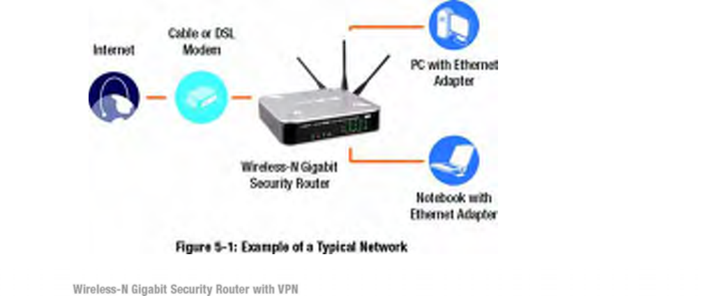
Figure 5-1: Example of a Typical Network 16
Figure 5-2: Connect a PC 17
Figure 5-3: Connect the Internet 17
Figure 5-4: Connect the Power 17
Figure 5-5: The Stand Option 18
Figure 5-6: Stand 18
Figure 5-7: Mounting Dimensions 19
Figure 5-8: Wall Mounting Hardware 19
Figure 6-1: Router’s IP Address 21
Figure 6-2: Login Screen for Web-based Utility 21
Figure 6-1: Setup - IP Versions 25
Figure 6-2: Setup - WAN (DHCP) 26
Figure 6-3: Setup - WAN (Static IP) 26
Figure 6-4: Setup - WAN (PPPoE) 27
Figure 6-5: Setup - WAN (PPTP) 27
Figure 6-6: Setup - WAN (Heart Beat Signal) 28
Figure 6-7: Setup - WAN (L2TP) 29
Figure 6-8: Setup - WAN (Optional Settings) 30
Figure 6-9: Setup - WAN (DynDNS.org) 31
Figure 6-10: Setup - WAN (TZO.com) 31
Figure 6-11: Setup - LAN 32
Figure 6-12: Setup - DMZ 34

Figure 6-13: Setup - MAC Address Clone 34
Figure 6-14: Setup - Advanced Routing 35
Figure 6-15: Setup - Advanced Routing (Routing Table) 36
Figure 6-16: Setup - Time 37
Figure 6-17: Wireless - Basic Wireless Settings 38
Figure 6-18: Wireless - Wireless Security (Disabled) 40
Figure 6-19: Wireless - Wireless Security (WPA-Personal) 40
Figure 6-20: Wireless - Wireless Security (WPA2-Personal) 41
Figure 6-21: Wireless - Wireless Security (WPA2-Personal Mixed) 41
Figure 6-22: Wireless - Wireless Security (WPA-Enterprise) 42
Figure 6-23: Wireless - Wireless Security (WPA2-Enterprise) 42
Figure 6-24: Wireless - Wireless Security (WPA2-Enterprise Mixed) 43
Figure 6-25: Wireless - Wireless Security (WEP) 43
Figure 6-26: Wireless - Wireless Connection Control 44
Figure 6-27: Select MAC Address from Wireless Client List 44
Figure 6-28: Wireless - Advanced Wireless Settings 45
Figure 6-29: Firewall - Basic Settings 47
Figure 6-30: Firewall - IP Based ACL 49
Figure 6-31: Firewall - IP Based ACL (pre-defined services) 49
Figure 6-32: Firewall - IP Based ACL (Service definition) 50
Figure 6-33: Firewall - Edit IP ACL Rule 50
Figure 6-34: Firewall - Internet Access Policy 52
Figure 6-35: Firewall - Internet Access Policy Summary 53
Figure 6-36: Firewall - Internet Access Policy (List of PCs to apply policy)
53
Figure 6-37: Firewall - Single Port Forwarding 54
Figure 6-38: Port Range Forwarding 55
Figure 6-39: Port Range Triggering 56
Figure 6-40: Firewall - Services 57
Figure 6-41: VPN - IPsec VPN 58
Figure 6-42: VPN Tunnel Summary 58
Figure 6-43: View VPN Tunnel Log 60
Figure 6-44: IPsec VPN Advanced Settings 61
Figure 6-45: VPN - VPN Client Accounts 63

Figure 6-46: VPN - VPN Passthrough 64
Figure 6-47: QoS - Application Based 65
Figure 6-48: Port-based 66
Figure 6-49: Administration - Management 67
Figure 6-50: Administration - Log 68
Figure 6-51: View Log pop-up window 68
Figure 6-52: Administration - Diagnostics 69
Figure 6-53: Ping Test Screen 69
Figure 6-54: Trace Route Test Screen 70
Figure 6-55: Administration - Config Management 70
Figure 6-56: Administration - Factory Default 71
Figure 6-57: Administration - Firmware Upgrade 71
Figure 6-58: IPS - Configuration 72
Figure 6-59: IPS - P2P / IM 73
Figure 6-60: IPS - Report 74
Figure 6-61: IPS Log Raw Data 74
Figure 6-62: IPS - Information 75
Figure 6-63: L2 Switch - VLAN 76
Figure 6-64: L2 Switch - RADIUS 77
Figure 6-65: L2 Switch - RADIUS 77
Figure 6-66: L2 Switch - Port Settings 78
Figure 6-67: L2 Switch - Cable Diagnostics 79
Figure 6-68: Status - WAN / Gateway 80
Figure 6-69: Status - LAN 81
Figure 6-70: LAN DHCP Client Table 81
Figure 6-71: LAN ARP Table 81
Figure 6-72: Status - Wireless LAN 82
Figure 6-73: Status - System Performance 83
Figure 6-74: Status - VPN Clients 84
Figure 6-75: Status - IPsec VPN 84
Figure B-1: VPN Client Accounts Screen 99
Figure B-2: QuickVPN Desktop Icon 101
Figure B-3: QuickVPN Tray Icon - No Connection 101
Figure B-4: QuickVPN Software - Profile 101
Figure B-5: Connecting 101

Figure B-6: Activating Policy 101
Figure B-7: Verifying Network 101
Figure B-8: QuickVPN Software - Status 102
Figure B-9: QuickVPN Tray Icon - Connection 102
Figure B-10: QuickVPN Tray Icon - No Connection 102
Figure B-11: QuickVPN Software - Change Password 102
Figure C-1: Diagram of Gateway-to-Gateway VPN Tunnel 103
Figure C-2: Login Screen 104
Figure C-3: VPN - IPsec VPN Configuration 104
Figure C-4: Advanced IPsec VPN Tunnel Settings 106
Figure C-5: Auto (IKE) Advanced Settings Screen 106
Figure D-1: IP Configuration Screen 108
Figure D-2: MAC Address/Adapter Address 108
Figure D-3: MAC Address/Physical Address 109
Figure D-4: MAC Address Clone 109

Chapter 1: Introduction
Welcome
Thank you for choosing the Wireless-N Gigabit Security Router with VPN. The Wireless-N Gigabit
Security Router with VPN is an advanced Internet-sharing network solution for your small business needs.
The Router features a built-in 4-Port full-duplex 10/100/1000 Ethernet switch to connect four PCs directly,
or you can connect more hubs and switches to create as big a network as you need. Like any wireless router,
it lets multiple computers in your office share an Internet connection through both wired and wireless
connections. It can also be used as an intranet router to aggregate traffic to a company backbone network.
The Router has a built-in access point that supports the latest 802.11n draft specification by IEEE. It also
supports 802.11g and 802.11b clients in a mixed environment. The access point can support an 11n data
rate of up to 300 Mbps. Besides having a higher data rate, 802.11n technology also promises longer
coverage by using multiple antennas to transmit and receive data streams in different directions. Users are
encouraged to upgrade their firmware through www.linksys.com when 802.11n specification is finalized by
IEEE to ensure compatibility with all the wireless-N devices.
The Wireless-N Gigabit Security Router with VPN is equipped with advanced security technologies like
Intrusion Prevention System (IPS), Stateful Packet Inspection (SPI) Firewall, IP based Access List (IP
ACL), and Network Address Port Translation (NAPT, also called NAT as a more generic term). These
technologies work together by providing self-defensive strategy. Malicious attack traffic is identified,
classified, and stopped in real time while passing through the Router. Users are encouraged to update their
IPS signature file to stay current on stopping malicious worms. The SPI Firewall provides deep packet
inspection to analyze packets in network layer (IP) and transport layer (TCP, UDP) to block illegal packet
transactions. Users can also use IP based ACL to limit traffic to a specific source, destination and protocol.
NAPT allows users to open specific TCP/UDP port numbers to the Internet to provide limited service while
minimizing harmful traffic at the same time.
The Virtual Private Network (VPN) capability is another security feature that creates encrypted “tunnels”
through the Internet, allowing up to five remote offices and five traveling users to securely connect into
your office network from off-site. Users connecting through a VPN tunnel are attached to your company's
network with secure access to files, e-mail, and your intranet as if they were in the building. You can also
use the VPN capability to allow users on your small office network to securely connect out to a corporate
network. The QoS features provide consistent voice and video quality throughout your business.
This user guide will give you all the information you need to connect, set up, and configure your Router.
Ethernet: a network protocol that specifies how data is placed on and retrieved from a common
transmission medium.
This user guide covers the steps for setting up and using the Wireless-N Gigabit Security Router with VPN.
. • Chapter 1: Introduction This chapter describes the Wireless-N Gigabit Security Router
with VPN applications and this User Guide.
. • Chapter 2: Networking and Security Basics This chapter describes the basics of
networking and network security.
. • Chapter 3: Planning Your Virtual Private Network (VPN) This chapter describes a VPN
and its various applications.

. • Chapter 4: Getting to Know the Router This chapter describes the physical features of the
Router.
. • Chapter 5: Connecting the Router This chapter instructs you on how to connect the
Router to your network.
. • Chapter 6: Setting Up and Configuring the Router This chapter explains how to use the
Web-Based Utility to perform basic setup and configure its advanced settings.
. • Appendix A: Troubleshooting This appendix describes some problems and solutions, as
well as frequently asked questions, regarding installation and use of the Wireless-N Gigabit Security Router
with VPN.
. • Appendix B: Using the Linksys QuickVPN Software for Windows 2000 or XP This
appendix instructs you on how to use the Linksys QuickVPN software if you are using a Windows 2000 or
XP PC.
. • Appendix C: Configuring a Gateway-to-Gateway IPSec Tunnel This appendix describes
how to configure an IPSec VPN Tunnel between two VPN Routers.
. • Appendix D: Finding the MAC Address and IP Address for your Ethernet Adapter. This
appendix describes how to find the MAC address for your computer’s Ethernet adapter so you can use the
MAC filtering and/or MAC address cloning feature of the Router. It also explains how to find the IP
address for your computer.
. • Appendix E: Glossary This appendix gives a brief glossary of terms frequently used in
networking.
. • Appendix F: Specifications This appendix provides the technical specifications for the
Router.
. • Appendix G: Warranty Information This appendix supplies the warranty information for
the Router.
. • Appendix H: Regulatory Information This appendix supplies the regulatory information
regarding the Router.
. • Appendix I: Contact Information This appendix provides contact information for a
variety of Linksys resources, including Technical Support.

Chapter 2: Networking and Security
Basics
An Introduction to LANs
A Router is a network device that connects
multiple networks together and forward traffic
based on IP destination of each packet.
The Wireless-N Gigabit Security Router can connect your local area network (LAN) or a group of PCs
interconnected in your home or office to the Internet. You can use one public IP address from the ISP
through WAN port and use the router’s Network Address Translation (NAT) technology to share this single
IP address NAT (Network Address Translation):
among all the users. NAT technology translates IP
a
ddresses of a local area network to a The Router’s Network Address Port Translation (NAPT or NAT)
technology protects your network of PCs so users different IP address for the Internet. on the Internet
cannot “see” your PCs. This is how your LAN remains private. The Router protects your network by
inspecting the first packet coming in through the Internet port before delivery to the final destination on one
of the Ethernet ports. The Router inspects Internet port services like the web server, ftp server, or other
Internet LAN: the computers and networking products that applications, and, if allowed, it will forward the packet to the
appropriate PC on the LAN side. make up your local network
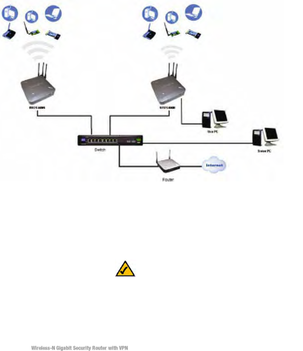
Multiple Wireless-N Gigabit Security Routers can also be used to connect multiple LANs
together. This usually applies to a medium-sized or larger company where you want to
divide your network into multiple IP subnets to increase the intranet throughput and
reduce the size of the IP broadcast domain and its interference. In this case, you need one
WRVS4400Nv2 for each subnetwork and you can connect all the WAN ports to a second
level Router or switch to the Internet. Note that the second level Router only forwards
data packets through a wired network so you don’t have to use the Wireless-N Gigabit
Security Router. You can use any wired router in the Linksys family, e.g. RVS4000,
which has 4 LAN ports and 1 WAN port.
The following diagram shows an example that consists of two levels of routers and
multiple LANs inter-connected together. The wireless network is only available at the
first level of router to provide end user connections. The second level router can connect
to dedicated Server PCs or routers that aggregates traffic from different LANs.
The Use of IP Addresses
IP stands for Internet Protocol. Every device in an IP-based network, including PCs, print servers, and
routers, requires an IP address to identify its location, or address, on the network. This applies to both the
Internet and LAN connections.
There are two ways of assigning IP addresses to your network devices.
NOTE: Since the Router is a device that connects two networks, it needs two IP addresses—one for the
LAN, and one for the Internet. In this User Guide, you’ll see references to the “Internet IP address” and the
“LAN IP address.”
Since the Router uses NAT technology, the only IP address that can be seen from the Internet for your
network is the Router’s Internet IP address. However, even this Internet IP address can be hidden on the
Internet by suppressing PING response.
A static IP address is a fixed IP address that you assign manually to a PC or other device on the network.
Since a static IP address remains valid until you disable it, static IP addressing ensures that the device

assigned it will always have that same IP address until you change it. Static IP addresses are commonly
used with dedicated network devices such as server PCs or print servers. Since a user’s PC is moving
around in a network and is being powered on or off, it does not require a dedicated IP address that could be
a precious resource in your network.
If you use the Router to share your cable or DSL Internet connection, contact your ISP to find out if
they have assigned a static IP address to your account. If so, you will need that static IP address when
configuring the Router. You can get the information from your ISP.
A dynamic IP address is automatically assigned to a device on the network. This IP address is called
dynamic because it is only temporarily assigned to the PC or other device. After a certain time period, it
expires and may change. If a PC logs onto the network (or the Internet) and its dynamic IP address has
expired, the DHCP server will assign it a new dynamic IP address. Most ISPs use dynamic IP addresses for
their customers. By default, the Router’s Internet Connection Type is Obtain an IP automatically
(DHCP).
For DSL users, many ISPs may require you to log on with a user name and password to gain access to the
Internet. This is a dedicated, high-speed connection type called Point-to-Point Protocol over Ethernet
(PPPoE). PPPoE is similar to a dial-up connection, which establishes a PPP session with an ISP server
through the DSL connection. The server will also provide the Router with a dynamic IP address to
establish a connection to the Internet.
A DHCP server can either be located on a designated PC on the network or another network device, such as
the Router. The PC or network device obtaining an IP address is called the DHCP client. DHCP frees you
from having to assign IP addresses manually every time a new user is added to your network. For this
Wireless-N Router, a DHCP client is running on a WAN port for most configurations. A DHCP server is
running on the LAN side to provide services.
By default, a DHCP server is enabled on the Router. If you already have a DHCP server running on your
network, you MUST disable one of the two DHCP servers. If you run more than one DHCP server on your
network, you will experience network errors, such as conflicting IP addresses. To disable DHCP on the
Router, refer to the Basic Setup section in “Chapter 6: Setting Up and Configuring the Router.”
Static IP address: a fixed address assigned to a computer or device that is connected to a network.
Dynamic IP address: a temporary IP address assigned by a DHCP server.
DHCP (Dynamic Host Configuration Protocol): a protocol that lets one device on a local network, known
as a DHCP server, assign temporary IP addresses to the other network devices, typically computers.
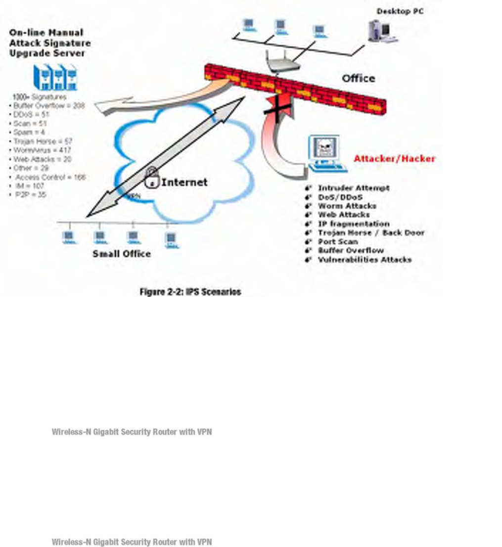
IPS is an advanced technology to protect your network from malicious attacks. IPS works together with
your SPI Firewall, IP Based Access List (IP ACL), Network Address Port Translation (NAPT), and Virtual
Private Network (VPN) to achieve the highest amount of securities.
IPS works by providing real-time detection and prevention as an in-line module in a router. The Wireless-N
Security Router has hardware-based acceleration for real-time pattern matching for malicious attacks. It
actively filters and drops malicious TCP/UDP/ICMP/IGMP packets and can reset TCP connections. This
protects your client PCs and servers running various operating systems including Windows, Linux, and
Solaris from network worm attacks. However, this system does not prevent viruses attached emails.
The signature file is the heart of the IPS system. It is similar to the Virus definition files on your PC’s
Anti-Virus programs. IPS uses this file to match against packets coming in to the Router and performs
actions accordingly. As of today, the Wireless-N Router is shipped with signature file version 1.1.4 and
with a total of 1048 rules. The rules cover the following categories: DDoS, Buffer Overflow, Access
Control, Scan, Trojan Horse, Misc., P2P, IM, Virus, Worm, and Web Attacks.
Customers are encouraged to update their IPS signature file regularly to prevent any new type of attacks
on the Internet.
Chapter 3: Planning Your Virtual
Private Network (VPN)
Why do I need a VPN?
Computer networking provides a flexibility not available when using an archaic, paper-based system. With
this flexibility, however, comes an increased risk in security. This is why firewalls were first introduced.
Firewalls help to protect data inside of a local network. But what do you do once information is sent
outside of your local network, when e-mails are sent to their destination, or when you have to connect to
your company's network when you are out on the road? How is your data protected?
That is when a VPN can help. VPNs are called Virtual Private Networks because they secure data moving
outside of your network as if it were still within that network.
When data is sent out across the Internet from your computer, it is always open to attacks. You may already
have a firewall, which will help protect data moving around or held within your network from being
corrupted or intercepted by entities outside of your network, but once data moves outside of your
network—when you send data to someone via e-mail or communicate with an individual over the
Internet—the firewall will no longer protect that data.
At this point, your data becomes open to hackers using a variety of methods to steal not only the data you
are transmitting but also your network login and security data. Some of the most common methods are as
follows:
1) MAC Address Spoofing
Packets transmitted over a network, either your local network or the Internet, are preceded by a packet
header. These packet headers contain both the source and destination information for that packet to transmit
efficiently. A hacker can use this information to spoof (or fake) a MAC address allowed on the network.
With this spoofed MAC address, the hacker can also intercept information meant for another user.
2) Data Sniffing
Data “sniffing” is a method used by hackers to obtain network data as it travels through unsecured
networks, such as the Internet. Tools for just this kind of activity, such as protocol analyzers and network
diagnostic tools, are often built into operating systems and allow the data to be viewed in clear text.
3) Man in the middle attacks
Once the hacker has either sniffed or spoofed enough information, he can now perform a “man in the
middle” attack. This attack is performed, when data is being transmitted from one network to another, by
rerouting the
vpn (virtual private network): a security measure to protect data as it leaves one network and goes to
another over the Internet

packet: a unit of data sent over a network
These are only a few of the methods hackers use and they are always developing more. Without the
security of your VPN, your data is constantly open to such attacks as it travels over the Internet. Data
travelling over the Internet will often pass through many different servers around the world before
reaching its final destination. That's a long way to go for unsecured data and this is when a VPN serves its
purpose.
What is a VPN?
A VPN, or Virtual Private Network, is a connection between two endpoints—a VPN Router, for
instance—in different networks that allows private data to be sent securely over a shared or public
network, such as the Internet. This establishes a private network that can send data securely between
these two locations or networks.
This is done by creating a “tunnel”. A VPN tunnel connects the two PCs or networks and allows data
to be transmitted over the Internet as if it were still within those networks. Not a literal tunnel, it is a
connection secured by encrypting the data sent between the two networks.
There are two popular ways to establish a secured tunnel over the Internet — IPsec (IP Security) and SSL
(Secure Sockets Layer). IPsec runs on top of the IP layer and SSL runs over HTTP sessions. IPsec provides
better data throughput and SSL offers ease of use without the need of VPN client applications. The
Wireless-N Gigabit Security Router supports IPsec VPN for maximum throughput on data security.
VPN was created as a cost-effective alternative to using a private, dedicated, leased line for a private
network. Using industry standard encryption and authentication techniques—IPsec, short for IP
Security—the VPN creates a secure connection that, in effect, operates as if you were directly connected to
your local network. Virtual Private Networking can be used to create secure networks linking a central
office with branch offices, telecommuters, and/or professionals on the road (travelers can connect to a VPN
Router using any computer
encryption: encoding data transmitted in a network ip (internet protocol): a protocol used to send data
over a network software: instructions for the computer
. • VPN Router to VPN Router
. • Computer (using the Linksys VPN client software) to VPN Router
The VPN Router creates a “tunnel” or channel between two endpoints, so that data
transmissions between them are secure. A computer with the Linksys VPN client
software can be one of the two endpoints (refer to “Appendix
C: Using the Linksys QuickVPN Software for Windows 2000 or XP”). If you choose not
to run the VPN client software, any computer with the built-in IPsec Security Manager
(Microsoft 2000 and XP) allows the VPN Router
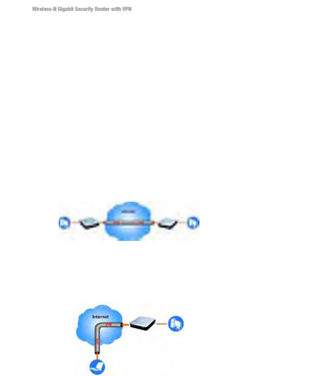
VPN Router to VPN Router
An example of a VPN Router-to-VPN Router VPN would be as follows. At home, a telecommuter uses his
VPN Router for his always-on Internet connection. His router is configured with his office's VPN settings.
When he connects to his office's router, the two routers create a VPN tunnel, encrypting and decrypting
data. As VPNs utilize the Internet, distance is not a factor. Using the VPN, the telecommuter now has a
secure connection to the central office's network, as if he were physically connected. For more information,
refer to “Appendix C: Configuring a Gateway-to-Gateway IPsec Tunnel.”
Computer (using the Linksys VPN client software) to VPN Router
The following is an example of a computer-to-VPN Router VPN. In her hotel room, a traveling
businesswoman dials up her ISP. Her notebook computer has the Linksys VPN client software, which is
configured with her office's IP address. She accesses the Linksys VPN client software and connects to the
VPN Router at the central office. As VPNs utilize the Internet, distance is not a factor. Using the VPN, the
businesswoman now has a secure connection to the central office's network, as if she were physically
connected.
For additional information and instructions about creating your own VPN, please visit Linksys’s website at
www.linksys.com. You can also refer to “Appendix B: Using the Linksys QuickVPN Software for
Windows 2000 or XP” and “Appendix C: Configuring a Gateway-to-Gateway IPsec Tunnel.”
Home Office
PC 1 WRVS4400Nv2VPN Router PC 2
Office
WRVS4400Nv2 PC 2
Off-site
Laptop running Linksys VPN Client Software

Chapter 4: Getting to Know the
Router
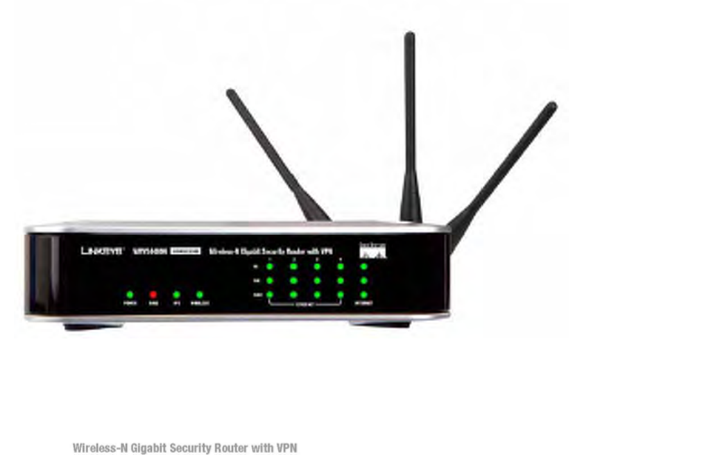
The Front Panel
The Router’s LEDs are located on the front panel of the Router.
LEDs
POWER Green. The POWER LED lights up when the Router is powered on. The LED
flashes when the Router runs a diagnostic test.
IPS Green/Red. The IPS LED lights up when the IPS function is enabled. The LED
light is off when the IPS functions are disabled. The IPS LED flashes green when
an external attack is detected. The IPS LED flashes red when an internal attack is
detected.
WIRELESS Green. The WIRELESS LED lights up when the wireless module is enabled. The
LED is off when the wireless module is disabled. The WIRELESS LED flashes
green when the data is transmitting or receiving on the wireless module.
1-4 (ETHERNET) Green. For each port, there are three LEDs. If the corresponding LED is
continuously lit, the Router is connected to a device at the speed indicated through
the corresponding port (1, 2, 3, or 4). The LED flashes when the Router is actively
sending or receiving data.
INTERNET Green. The INTERNET LED lights up the appropriate LED depending upon the
speed of the device that is attached to the Internet port. If the Router is connected
to a cable or DSL modem, typically the 10 LED will be the only LED lit up (i.e.
10Mbps). The LED Flashes during activity.
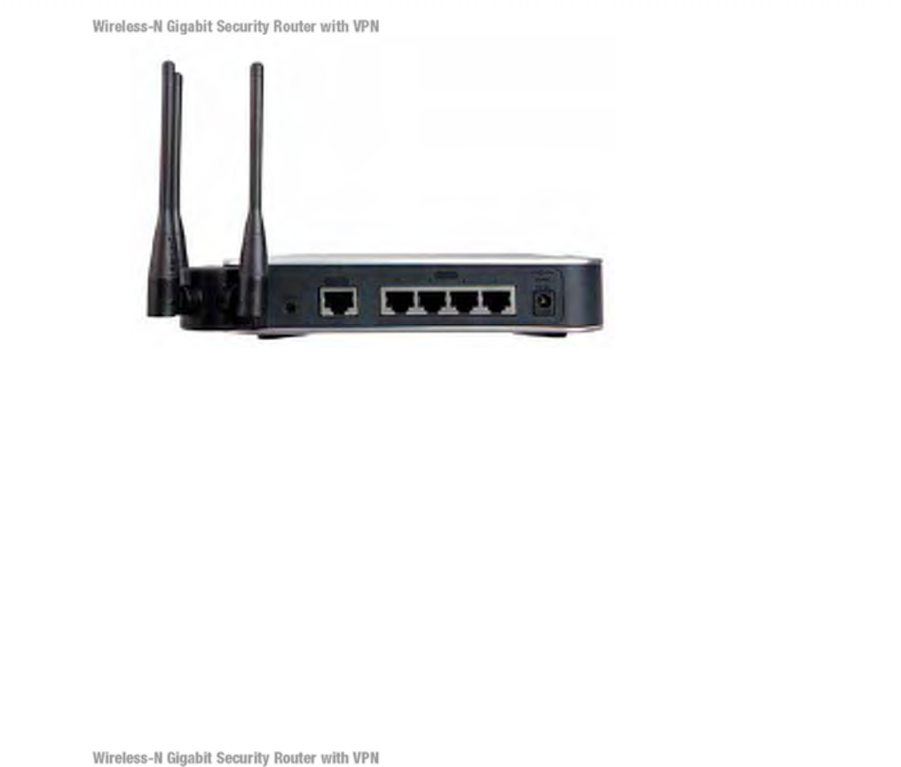
Figure 4-2: Back Panel
Reset Button
The Reset button can be used in one of two ways:
If the Router is having problems connecting to the Internet, press the Reset button
for just a second with a paper clip or a pencil tip. This is similar to pressing the
Reset button on your PC to reboot it.
If you are experiencing extreme problems with the Router and have tried all other
troubleshooting measures, press and hold in the Reset button for 10 seconds. This
will restore the factory defaults and clear all of the Router’s settings, such as port
forwarding or a new password.
Ports
INTERNET The INTERNET port connects to a cable or DSL modem.
1-4
(ETHERNET) The four ETHERNET ports connect to network devices, such as PCs, print servers,
or additional switches.
POWER The POWER port is where you will connect the included AC power cable.
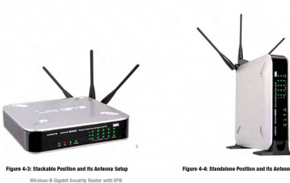
The Access Point can be placed in three different positions. It can be either stackable,
standalone, or wall-mount.
Antenna The Access Point has three non-detachable 1.8dBi omni-directional
antennas. The three antennas have a base that can rotate 90 degrees
when in the standing position. The three antennas will all be used to
support 2X3 MIMO diversity in wireless-N mode.
Chapter 5: Connecting the Router
Overview
To set up your network, you will do the following:
. • Connect the Router to one of your PCs according to the instructions in this chapter.
. • By default, Windows 98, 2000, Millennium, and XP computers are set to obtain an IP
address automatically, so unless you have changed the default setting, then you will not need to configure
your PCs. (If you do need to configure your PCs, refer to Windows Help for more information.)
. • Set up and configure the Router with the setting(s) provided by your Internet Service
Provider (ISP) according to “Chapter 6: Setting Up and Configuring the Router.”
The installation technician from your ISP should have left the setup information with you after installing
your broadband connection. If not, you can call your ISP to request the information. Once you have the
setup information for your specific type of Internet connection, then you can begin installation and setup of
the Router.
Ethernet Adapter
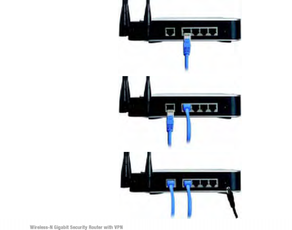
1. 1. Before you begin, make sure that all of your hardware is powered off, including the
Router, PCs, hubs, switches, and cable or DSL modem.
2. Connect one end of an Ethernet network cable to one of the numbered ports on the back
of the Router. Connect the other end to an Ethernet port on a network device, e.g., a PC, print server, hub,
or switch.
Repeat this step to connect more PCs or other network devices to the Router.
2. 3. Connect your cable or DSL modem’s Ethernet cable to the Router’s Internet port.
3. 4. Power on the cable or DSL modem and the other network device if using one.
4. 5. Connect the included AC power cable to the Router’s Power port on the side of the
Router, and then plug the power adapter into an electrical outlet.
The Power LED on the front panel will light up as soon as the power adapter is connected properly.
Proceed to “Chapter 6: Setting Up and Configuring the Router.”
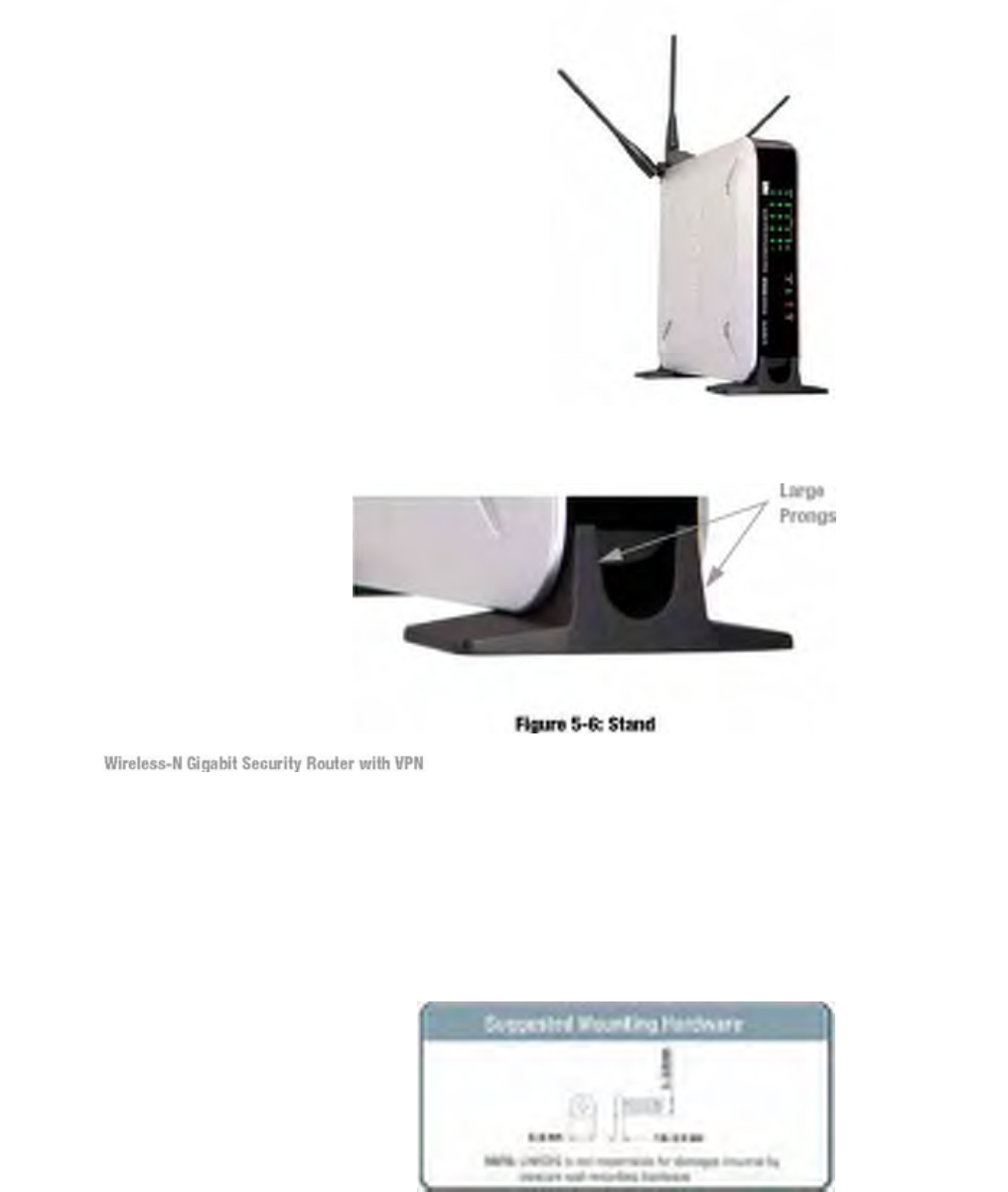
There are three ways to place the Wireless-N Router. The first way is to place it
horizontally on a surface, so it sits on its four rubber feet. The second way is to stand the
Wireless Router vertically on a surface. The third way is to mount it on a wall. The stand
and wall-mount options are explained in further detail below.
Stand Option
1. 1. Locate the Router’s left side panel.
2. 2. The Router includes two stands. With the two large prongs facing outward, insert the
short prongs into the little slots in the Router, and push the stand upward until it snaps into place.
Repeat this step with the other stand.
Now that the hardware installation is complete, proceed to “Chapter 6: Setting up and
Configuring the
Wireless-N Router,” for directions on how to set up the Wireless-N Router."
Figure 5-5: The Stand Option
You will need two suitable screws (See Figure 5-7) to mount the Router. Make sure the
screw size can fit into the criss-cross wall-mount slots.
1. 1. On the Wireless Router’s back panel are two criss-cross wall-mount slots.
2. 2. Determine where you want to mount the Wireless Router, and install two screws that are
2-9/16 in (64.5mm) apart.
3. 3. Line up the Wireless Router so that the wall-mount slots line up with the two screws.
Figure 5-7: Mounting Dimensions
4. 4. Place the wall-mount slots over the screws and slide the Wireless Router down until the
screws fit snugly into the wall-mount slots.
Now that the hardware installation is complete, proceed to “Chapter 6: Setting up and
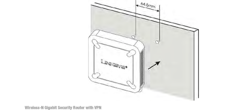
Configuring the Wireless-N Router,” for directions on how to set up the Wireless-N
Router."
Chapter 6: Setting Up and
Configuring the Router
Overview
The Wireless Router has been designed to be functional right out of the box with the default settings.
However, if you'd like to change these settings, the Wireless Router can be configured through your web
browser with the Web-based Utility. This chapter explains how to use the Utility to perform the most basic
settings.
The Utility can be accessed via web browsers, such as Microsoft Internet Explorer or Mozilla Firefox
through the use of a computer that is networked with the Wireless Router.
Basic Setup
For a basic network setup, most users only need to use the following screens of the Utility:
•Setup->WAN Click the Setup tab and then select the WAN screen. Select the appropriate Internet
Connection Type according to your ISP if connecting your WAN port to the WAN (DSL or cable modem).
Otherwise, most cases can leave the default setting to get a WAN port IP address from a DHCP server.
•Setup->Advanced Routing Click the Setup tab and then select the Advanced Routing screen. If you are
connecting the Router to the Internet, leave the default setting. Otherwise, choose the Intranet Router
Operation Mode to disable NAT (Network Address Translation).
•Management Click the Administration tab and then select the Management screen. Change the access
password for the Router’s Web-based Utility. The default username and password are admin.
Most users will also customize their wireless settings:
•Wireless On the Wireless screen, change the default SSID on the Basic Settings Tab. Select the level of
security under the Security Settings Tab and complete the options for the selected security mode. When
the appropriate security mode is configured, disable SSID Broadcast on the Basic Settings Tab.
There are two ways to connect to your Wireless Router for the first time.
1. Connect your PC to one of the four LAN ports on the Router. (Refer to "Chapter 5: Connecting the
Router.") Then, configure your PC to obtain IP address automatically through a DHCP server.
2. Although it is not recommended, you can also connect your PC wirelessly to the Wireless Router. Then,
configure the wireless interface of your PC to obtain IP address automatically through a DHCP server.
It is not recommended, because you can easily lose your connection through wireless configuration
changes.
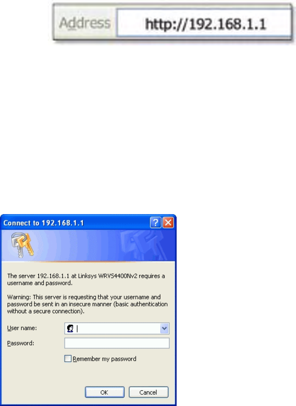
To access the Web-based Utility of the Router:
•Launch a web browser, such as Internet Explorer or Mozilla Firefox, and enter the Router’s default IP
address, 192.168.1.1, in the Address field. Press the Enter key.
•A screen will appear asking you for your User name and Password. Enter admin in the User Name field,
and enter your password (default password is admin) in the Password field. Then click the OK button.
How to Navigate the Utility
The Web-based Utility consists of the following nine main tabs: Setup, Wireless, Firewall,
VPN, QoS, Administration, IPS, L2 Switch and Status. Additional screens (sub tabs) will
be available from most of the main tabs.
The following briefly describes the main & sub tabs of the Utility.
Setup
You will use the Setup tabs to define the Router’s basic functionality.
•Summary. This screen displays a read-only summary of the Router’s basic information.
•WAN. The Internet connection settings are entered and displayed on this screen.
•LAN. The Local Area Network (LAN) settings are entered and displayed on this screen.
•DMZ. The DMZ (Demilitarized Zone) Host feature allows one local user to be exposed to the Internet to
use a special-purpose service such as Internet gaming or video conferencing.
•MAC Address Clone. Some ISPs require that you register a MAC address. This feature clones your
network adapter's MAC address onto the Router, which prevents you from having to call your ISP to
change the registered MAC address to the Router's MAC address.
•Advanced Routing. Select the Router’s operation mode either connecting to the Internet or Intranet (NAT
is only enabled while connecting to the Internet). Configure dynamic or static routing. The Router support
RIP version 1 and 2 to automatically exchange routing information and establish its routing table.
•Time. Change the time settings on this screen.
•IP Mode. This screen provides options for IPv4 mode or Dual-Stack IPv4 and IPv6 mode.
Wireless
You will use the Wireless tabs to enter a variety of wireless settings for the built-in access point of the
Router.
•Basic Settings. Choose the wireless network mode (e.g. B/G/N-Mixed), SSID, and radio channel on this
screen.
•Security Settings. Use this screen to configure the built-in access point’s security settings.
•Connection Control. Use this screen to control the wireless connections from client devices to the Router.
•Advanced Settings. Use this screen to configure the built-in access point’s more advanced wireless settings
(e.g. Tx Rate Limiting, Channel Bandwidth, etc.).
•VLAN & QoS. Use this screen to configure the 802.1Q VLAN and the QoS (Quality of Service) settings.
•WDS. Use this screen to configure WDS (Wireless Distribution System) settings.
Firewall
You will use the Firewall tabs to configure basic firewall settings, IP access list, and Network
Address Port Translation settings for your network’s security.
•Basic Settings. Basic Firewall settings are configured from here.
•IP Based ACL. Define IP based Access List to block specific hosts, networks, and protocols (services).
•Internet Access Policy. This screen defines the time schedule to allow or block complete Internet access or
to specific URLs from the Router.
•Single Port Forwarding. Use this screen to set up public services or other specialized Internet applications
with a single port on your network.
•Port Range Forwarding. Use this screen to set up public services or other specialized Internet applications
on your network using a port range.
•Port Range Triggering. Use this screen to set up triggered ranges and forwarded ranges to allow special
Internet applications to pass through this NAT Router.
•Service. Use this screen to define customized IP applications based on TCP or UDP. The user-defined
service type will be available when defining IP based ACL rules.
VPN
You will use VPN tabs to configure VPN tunnels and accounts to establish a secured channel through
Internet.
•Summary. This displays the Summary of IPSec tunnel Status..
•IPSec VPN. The VPN Router can create one or multiple tunnels (or secure channel) that each connect
between two endpoints, so that the transmitted data or information between these endpoints is secure.
•VPN Client Accounts. Use this screen to designate VPN clients and their passwords.
•VPN Pass Through. This tab allows you to disable IPSec Passthrough, PPTP Passthrough, and L2TP
Passthrough.
QoS
The Router support two types of Quality of Service (QoS) traffic.
•Bandwidth Management. This allows you to perform Bandwidth Management, by either Rate Control or
Priority.
•QoS Setup. This allows users to configure QoS Trust Mode for each LAN port.
•DSCP Settings. This allows you to set the DSCP (Differentiated Services Code Point) settings.
Administration
You will use Administration tabs for systems administration purposes.
•Management. You can alter the Router’s password, its access privileges, SNMP settings, and UPnP
settings on this screen.
•Log. This screen allows the configuration of Log settings.
•Diagnostic. This screen allows you to run ping tests and display test results.
•Backup & Restore. You can back up and restore the Gateway's configuration file in this screen.
•Factory Defaults. If you need to restore the Router’s factory defaults, use this screen.
•Reboot. Use this screen to reboot the Router.
•Firmware Upgrade. Use this screen to upgrade the Router’s firmware.
IPS
You will use this tab for advanced configuration on built-in Intrusion Prevention System (IPS) inside the
Router.
•Configuration. Enable or disable IPS functions from this screen.
•P2P/IM. Allows or blocks specific Peer to Peer (P2P) networks and Instant Messaging (IM) applications.
•Report. Provides reports of network traffic and malicious attacks.
• Information. Provides the signature file version and the Protection Scope of the IPS system.
L2 Switch
You will use this tab to configure layer 2 switching features on the 4 port Ethernet Switch (LAN ports only).
•Create VLAN. Virtual Local Area Network (VLAN) assignment is done on this screen.
•VLAN & Port Assignment. Virtual Local Area Network (VLAN) and Port settings are done on this screen.
•RADIUS. Used for configuration of Remote Authorization Dial-In User Service (RADIUS) settings.
•Port Setting. Allows configuration of port speeds and duplex.
•Statistics. This screen displays statistics for both received and transmitted packets..
•Port Mirroring. Allows configuration of port mirroring.
•RSTP. Used for RSTP (Rapid Spanning Tree Protocol) configuration.
Status
You will use this tab to get the current status on the Router.
•Gateway. This screen provides basic information like firmware version and status information on the
WAN port.
•Local Network. This screen provides status information about the local network (four Ethernet Ports).
•Wireless LAN. This screen provides status information on Wireless LAN.
•System Performance. This screen provides traffic statistics on LAN and Wireless LAN ports.
Setup
The Setup screen contains all of the Router’s basic setup functions. The Router can be
used in most network settings without changing any of the default values. Some users
may need to enter additional information in order to connect to the Internet through an
ISP (Internet Service Provider) or broadband (DSL, cable modem) carrier.
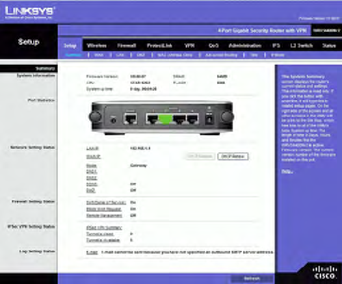
Summary
System Information
Firmware version Displays the Router’s current software version.
CPU Displays the Router’s CPU type.
System up time Displays the length of time that has elapsed since the Router was last
reset.
DRAM Displays the amount of DRAM installed in the Router.
Flash Displays the amount of flash memory installed in.
Port Statistics
This section displays the following color-coded status information on the Router’s
Ethernet ports:
• Green Indicates that the port has a connection.
• Black Indicates that the port has no connection.
Network Setting Status
LAN IP Displays the IP address of the Router’s LAN interface.
WAN IP Displays the IP address of the Router’s WAN interface. If this address was
assigned using DHCP, click DHCP Release to release the address, or click DHCP Renew
to renew the address.
Mode Displays the operating mode, Gateway or Router.
DNS 1-2 The IP addresses of the Domain Name System (DNS) server(s) that the Router
is using.
DDNS Indicates whether the Dynamic Domain Name System (DDNS) feature is enabled.
DMZ Indicates whether the DMZ Hosting feature is enabled.
Firewall Setting Status
DoS (Denial of Service) Indicates whether the DoS Protection feature is enabled to block
DoS attacks.
Block WAN Request Indicates whether the Block WAN Request feature is enabled.
Remote Management Indicates whether the Remote Management feature is enabled.
IPSec VPN Setting Status
IPSec VPN Summary Click the IPSec VPN Summary hyperlink to display the VPN >
Summary screen.
Tunnel(s) Used Displays the number of VPN tunnels currently being used.
Tunnel(s) Available Displays the number of VPN tunnels that are available.
Log Setting Status
E-mail If this displays Email cannot be sent because you have not specified an outbound
SMTP server address, then you have not set up the mail server. Click the E-mail
hyperlink to display the Administration > Log screen where you can configure the SMTP
mail server.

WAN
The WAN Setup screen provides Internet Connection Type and DDNS configurations on
the WAN port of the Wireless Router. Before starting, you need to find out the Internet
Connection Type and settings used by your ISP. If the Router is used as an Intranet
Router, you can mostly use the default settings. If you want to use the dynamic DNS
feature, you will need to sign up for a DDNS service.
Internet Connection Type
The Router supports six connection types. Each WAN Setup screen and available options
will differ depending on what kind of connection type you select.
Automatic Configuration - DHCP
By default, the Router’s Configuration Type is set to Automatic Configuration - DHCP. The Router
will get its IP address from a DHCP server of the ISP. Most cable modem ISPs use this option.
Static IP
If your connection uses a permanent IP address to connect to the Internet, then select Static IP.
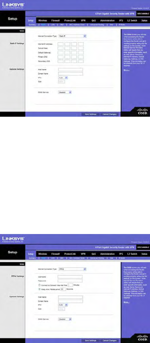
Internet IP Address. This is the Router’s IP address on the WAN port that can be reached from the
Internet. Your ISP will provide you with the IP Address you need to specify here.
Subnet Mask. This is the Router’s Subnet Mask on the WAN port. Your ISP will provide you this
information and your IP Address.
Default Gateway. Your ISP will provide you with the Default Gateway (Router) to reach the Internet.
Primary DNS (Required) and Secondary DNS (Optional). Your ISP will provide you with at least
one DNS (Domain Name System) Server IP Address to resolve host name to IP address mapping.
PPPoE
Most DSL-based ISPs use PPPoE (Point-to-Point Protocol over Ethernet) to establish Internet
connections. If you are connected to the Internet through a DSL line, check with your ISP to see if they
use PPPoE. If they do, you will have to enable PPPoE.
User Name and Password. Enter the User Name and Password provided by your ISP for PPPoE
authentication.
Connect on Demand: Max Idle Time. You can configure the Router to cut the Internet connection
after it has been inactive for a specified period of time (Max Idle Time). If your Internet connection has
been terminated due to inactivity, Connect on Demand enables the Router to automatically re-establish
your connection as soon as you attempt to access the Internet again. If you wish to activate Connect on
Demand, click the Connect on Demand option and enter the number of minutes you want to have
elapsed before your Internet connection terminates in the Max Idle Time field. Use this option to
minimize your DSL connection time if it is charged based on time. This option is disabled by default.
Keep Alive Redial period. This option allows the Router will periodically check your Internet
connection. If you are disconnected, then the Router will automatically re-establish your connection.
To use this option, click the option next to Keep Alive. In the Redial Period field, you specify how
often you want the Router to check the Internet connection. This option is enabled by default and the
default Redial Period is 30 seconds. Use this option to minimize your Internet connection response
time since it will always be connected.
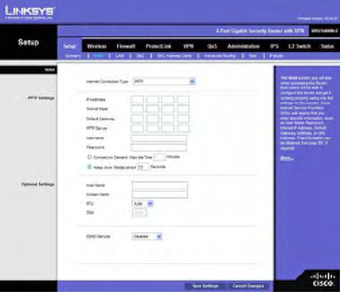
PPTP
Point-to-Point Tunneling Protocol (PPTP) is a service that applies to connections in Europe and Israel
only.
IP Address. This is the Router’s IP address, when seen from the WAN, or the Internet. Your ISP will
provide you with the IP Address you need to specify here.
Subnet Mask. This is the Router’s Subnet Mask. Your ISP will provide you the Subnet Mask and your
IP address.
Default Gateway. Your ISP will provide you with the Default Gateway IP Address.
PPTP Server. Enter the IP address of the PPTP server.
User Name and Password. Enter the User Name and Password provided by your ISP.
Connect on Demand: Max Idle Time. You can configure the Router to cut the Internet connection
after it has been inactive for a specified period of time (Max Idle Time). If your Internet connection has
been terminated due to inactivity, Connect on Demand enables the Router to automatically re-establish
your connection as soon as you attempt to access the Internet again. If you wish to activate Connect on
Demand, click the Connect on Demand option and enter the number of minutes you want to have
elapsed before your Internet connection terminates in the Max Idle Time field. Use this option to
minimize your DSL connection time if it is charged based on time. This option is disabled by default.
Keep Alive Redial period. If you select this option, the Router will periodically check your Internet
connection. If you are disconnected, then the Router will automatically re-establish your connection.
To use this option, click the option next to Keep Alive. In the Redial Period field, you specify how
often you want the Router to check the Internet connection. This option is enabled by default and the
default Redial Period is 30 seconds. Use this option to minimize your Internet connection response
time since it will always be connected.
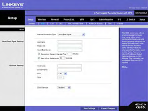
Heart Beat Signal
Heart Beat Signal is a service used in Australia. Check with your ISP for the necessary setup
information.
User Name and Password. Enter the User Name and Password provided by your ISP.
Heart Beat Server. Enter the IP address of the Heart Beat server.
Connect on Demand: Max Idle Time. You can configure the Router to cut the Internet connection
after it has been inactive for a specified period of time (Max Idle Time). If your Internet connection has
been terminated due to inactivity, Connect on Demand enables the Router to automatically re-establish
your connection as soon as you attempt to access the Internet again. If you wish to activate Connect on
Demand, click the Connect on Demand option and enter the number of minutes you want to have
elapsed before your Internet connection terminates in the Max Idle Time field. Use this option to
minimize your DSL connection time if it is charged based on time. This option is disabled by default.
Keep Alive Redial period. If you select this option, the Router will periodically check your Internet
connection. If you are disconnected, then the Router will automatically re-establish your connection.
To use this option, click the option next to Keep Alive. In the Redial Period field, you specify how
often you want the Router to check the Internet connection. This option is enabled by default and the
default Redial Period is 30 seconds. Use this option to minimize your Internet connection response
time since it will always be connected.
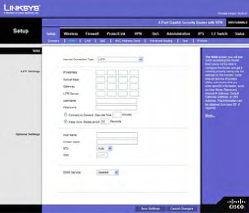
L2TP
Layer 2 Tunneling Protocol (L2TP) is a service that tunnels Point-to-Point Protocol (PPP) across the
Internet. It is used mostly in European countries. Check with your ISP for the necessary setup
information.
IP Address. This is the Router’s IP address, when seen from the WAN, or the Internet. Your ISP will
provide you with the IP Address you need to specify here.
Subnet Mask. This is the Router’s Subnet Mask. Your ISP will provide you with the Subnet Mask and
your IP address.
Gateway. Your ISP will provide you with the Default Gateway IP Address.
L2TP Server. Enter the IP address of the L2TP server.
User Name and Password. Enter the User Name and Password provided by your ISP.
Connect on Demand: Max Idle Time. You can configure the Router to cut the Internet connection
after it has been inactive for a specified period of time (Max Idle Time). If your Internet connection has
been terminated due to inactivity, Connect on Demand enables the Router to automatically re-establish
your connection as soon as you attempt to access the Internet again. If you wish to activate Connect on
Demand, click the Connect on Demand option and enter the number of minutes you want to have
elapsed before your Internet connection terminates in the Max Idle Time field. Use this option to
minimize your DSL connection time if it is charged based on time. This option is disabled by default.
Keep Alive Redial period. If you select this option, the Router will periodically check your Internet
connection. If you are disconnected, then the Router will automatically re-establish your connection.
To use this option, click the option next to Keep Alive. In the Redial Period field, you specify how
often you want the Router to check the Internet connection. This option is enabled by default and the
default Redial Period is 30 seconds. Use this option to minimize your Internet connection response
time since it will always be connected.
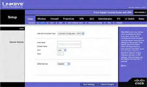
Option Settings (Required by some ISPs)
This section is common for all the Internet Connection Types. Some of these settings may be required
by your ISP. Verify with your ISP before making any changes.
Host Name: Some ISPs, usually cable ISPs, require a host name as identification. You may need to
check with your ISP to see if your broadband Internet service is configured with a host name. In most
cases you can leave this field blank.
Domain Name: Some ISPs, usually cable ISPs, require a domain name as identification. You may
need to check with your ISP to see if your broadband Internet service is configured with a domain
name. In most cases you can leave this field blank.
MTU: MTU is the Maximum Transmission Unit. It specifies the largest packet size permitted for
Internet transmission. Select Manual if you want to manually enter the largest packet size that is
transmitted. To have the Router select the best MTU for your Internet connection, keep the default
setting, Auto.
Size: When Manual is selected in the MTU field, this option is enabled. The recommended setting for
this field is 1500 (standard MTU size on Ethernet media).
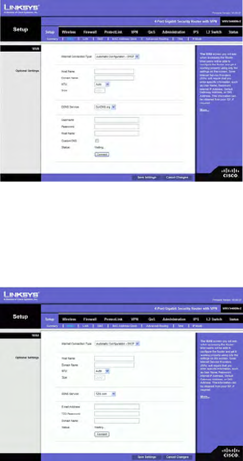
DDNS
The Router offers a Dynamic Domain Name System (DDNS) feature. DDNS lets you assign a fixed
host and domain name to a dynamic Internet IP address. It is useful when you are hosting your own
website, FTP server, or other server behind the Router.
Before you can use this feature, you need to sign up for DDNS service at DynDNS.org or TZO.com.
DDNS Service. If your DDNS service is provided by DynDNS.org, then select DynDNS.org from the
drop-down menu. If your DDNS service is provided by TZO.com, then select TZO.com from the
drop-down menu. To disable DDNS Service, select Disabled.
DynDNS.org
• User Name, Password, and Host Name. Enter the User Name, Password, and Host Name of the
account you set up with DynDNS.org.
• Status. The status of the DDNS service connection is displayed here.
TZO.com
• E-mail Address, TZO Password, and Domain Name. Enter the E-mail Address, Password, and
Domain Name of the account you set up with TZO.
• Status. The status of the TZO service connection is displayed here.
After entering the necessary information, the Router will advise the DDNS Service of
your current WAN (Internet) IP address whenever this address changes. If using TZO,
you should NOT use the TZO software to perform this “IP address update”.
Connect button: When DDNS is enabled, the Connect button is displayed. Use this
button to manually update your IP address information on the DDNS server. The Status
area on this screen also updates.
Click the Save Settings button to save the network settings or click the Cancel Changes
button to undo your changes.
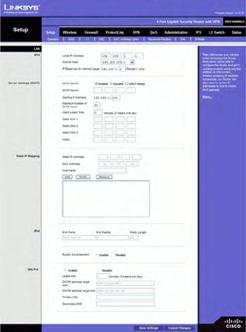
LAN
The LAN Setup section allows you to change the Router’s local network settings for the
four Ethernet ports.
IPv4
The Router’s Local IPv4 Address and Subnet Mask are shown here. In most cases, you
can keep the defaults.
Local IP Address. Enter the IPv4 address on the LAN side. The default value is
192.168.1.1.
Subnet Mask. Select the subnet mask from the drop-down menu. The default value is
255.255.255.0.
IP Reserved for Internal Usage. Enter the reserved IP between 1 and 254.
Server Settings (DHCP)
The Router can be used as your network’s DHCP (Dynamic Host Configuration Protocol)
server, which automatically assigns an IP address to each PC on your network. Unless
you already have one, it is highly recommended that you leave the Router enabled as a
DHCP server.
DHCP Server. DHCP is enabled by default. If you already have a DHCP server on your
network, or you don't want a DHCP server, then select Disable (no other DHCP features
will be available). If you already have a DHCP server on your network, and you want the
Router to act as a Relay for that DHCP Server, select DHCP Relay, then enter the DHCP
Server IP Address.
Starting IP Address. Enter a value for the DHCP server to start with when issuing IP
addresses. This value will automatically follow your local IP address settings. Normally,
you assign the first IP address for the Router (e.g. 192.168.1.1) so that you can assign an
IP address to other devices starting from the 2nd IP address (e.g. 192.168.1.2). The last
address in the subnet is for subnet broadcast (e.g. 192.168.1.255) so that the address
cannot be assigned to any host.
Maximum Number of DHCP Users. Enter the maximum number of PCs that you want
the DHCP server to assign IP addresses to. This number cannot be greater than the
available host addresses in the subnet (e.g. 253 for /24 subnet). In order to determine the
DHCP IP Address range, add the starting IP address (e.g., 100) to the number of DHCP
users.
Client Lease Time. This is the amount of time a DHCP client can keep the assigned IP
address before it sends a renewal request to the DHCP server. The default value is 0,
which actually means one day.
Static DNS 1-3. If applicable, enter the IP address(es) of your DNS server(s).
WINS The Windows Internet Naming Service (WINS) provides name resolution service
(similar to DNS) in Windows networks. If you use a WINS server, enter that server’s IP
Address here. Otherwise, leave this blank.
Static IP Mapping
Static IP Mapping is used to bind a specific IP address to a specific MAC address. This
helps external (WAN) users to access LAN servers that are advertised through NAPT port
forwarding. You can define up to 50 entries.
Static IP Address Enter the IP address to be mapped.
MAC Address Enter the MAC address to be mapped.
Host Name Enter the host name to be mapped.
Click Add to create the entry and add it to the list. To modify an existing entry, select it
from the list, edit the appropriate field(s), and then click Modify. To delete an entry,
select it and click Remove.
IPv6
Ipv6 Address If your network has implemented IPv6, enter the proper IPv6 address in
this field.
Prefix Length Enter the appropriate IPv6 prefix length.
Router Advertisement Enabling this option allows IPv6 hosts to configure their IP
addresses automatically using the IPv6 prefix broadcast by the router.
DHCPv6
To enable the DHCP v6 feature, select Enable. To disable DHCP v6, select Disable.
Lease time Enter the lease time in minutes.
DHCP address range start Enter the starting DHCP v6 IP address.
DHCP address range end Enter the ending DHCP v6 IP address.
Primary DNS Enter the Primary DHCP v6 DNS server address.
Secondary DNS Enter the Secondary DHCP v6 DNS server address.
Click the Save Settings button to save the network settings or click the Cancel Changes
button to undo your changes.
DMZ
The DMZ screen allows one local PC to be exposed to the Internet for use of a
special-purpose service, such as Internet gaming and video-conferencing. DMZ hosting
forwards traffic to all the ports for the specified PC simultaneously, unlike Port Range
Forwarding that can only forward a maximum of 10 ranges of ports.
DMZ Hosting. This feature allows one local PC to be exposed to the Internet for use of a
special-purpose service such as Internet gaming and video-conferencing. To use this
feature, select Enable. To disable the DMZ feature, select Disable.
DMZ Host IP Address. To expose one PC, enter the computer’s IP address.
Click the Save Settings button to save the network settings or click the Cancel Changes
button to undo your changes.
MAC Address Clone
Some ISPs require that you register a MAC address. This feature clones your PC network
adapter's MAC address onto the Router, and prevents you from having to call your ISP to
change the registered MAC address to the Router's MAC address. The Router's MAC
address is a 6-byte hexadecimal number assigned to a unique piece of hardware for
identification.
Mac Address Clone. Select Enabled or Disabled.
Mac Address. Enter the MAC Address registered with your ISP in this field.
Clone My PC’s MAC button. When Mac Address Clone is enabled, click this to copy
the MAC address of the network adapter in the computer that you are using to connect to
the Web-based utility.
Click Save Settings to save the MAC Cloning settings or click the Cancel Changes
button to undo your changes.
Advanced Routing
Operating Mode
Select the Operating mode in which the Router will function.
Gateway. This is the normal mode of operation. This allows all devices on your LAN to
share the same WAN (Internet) IP address. In the Internet Gateway mode, the NAT
(Network Address Translation) mechanism is enabled.
Router. You either need another Router to act as the Internet Gateway, or all PCs on your
LAN must be assigned (fixed) Internet IP addresses. In Intranet Router mode, the NAT
mechanism is disabled.
Dynamic Routing
The Router's dynamic routing feature can be used to automatically establish a routing
table through a database exchange with peer routers (running the same routing protocol).
The Router supports RIP (Routing Information Protocol) versions 1 & 2.
RIP (Routing Information Protocol. The Router, using the RIP protocol, calculates the
most efficient route for the network’s data packets to travel between the source and the
destination based upon the shortest paths.
RIP Send Packet Version. Choose the version of RIP packets you want to send to peers:
RIPv1 or RIPv2. This should match the version supported by other Routers on your LAN.
RIP Recv Packet Version. Choose the version of RIP packets you want to receive from peers:
RIPv1 or RIPv2. This should match the version supported by other Routers on your LAN.
Static Routing
Sometimes you will prefer to use static routes to build your routing table instead of using
dynamic routing protocols. Static routes do not require CPU resources to exchange
routing information with a peer router. You can also use static routes to reach peer routers
that do not support dynamic routing protocols. Static routes can be used together with
dynamic routes. Be careful not to introduce routing loops in your network.
To set up static routing, you should add route entries in the routing table that tell the
Router where to forward packets to specific IP destinations.
Enter the following data to create a static route entry:
1. Select Set Number. Select the set number (routing table entry number) that you wish to view or
configure. If necessary, click Delete This Entry to clear the entry.
2. Destination IP Address. Enter the network address of the remote LAN segment. For a standard Class
C IP domain, the network address is the first three fields of the Destination LAN IP; the last field
should be zero.
3. Subnet Mask. Enter the Subnet Mask used on the destination LAN IP domain. For Class C IP
domains, the Subnet Mask is 255.255.255.0.
4. Gateway. If this Router is used to connect your network to the Internet, then your gateway IP is the
Router’s IP Address. If you have another router handling your network’s Internet connection, enter the
IP Address of that router instead.
5. Hop Count. This value gives the number of nodes that a data packet passes through before reaching its
destination. A node is any device on the network, such as switches, PCs, etc. The maximum hop count
value is 16.
Show Routing Table button. Click this button to show the routing table established
either through dynamic or static routing methods.
Inter-VLAN Routing
Inter-VLAN Routing Select Enable to allow packets to be routed between VLANs that
are in different subnets. The default is Enable.
Click the Save Settings button to save the Routing settings, click the Cancel Changes
button to undo your changes or click the Show Routing Table button to view the current
routing table.
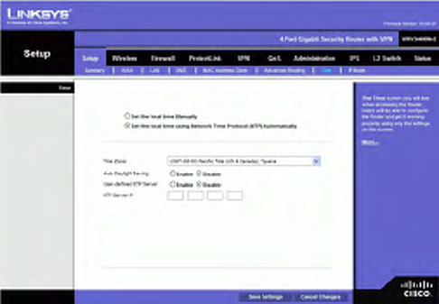
Time
You can either define your Router’s time manually or automatically through Time Server.
The default is Set the local time using Network Time Protocol (NTP) Automatically.
Manually
Set the local time Manually If you wish to enter the time and date manually, select this
option, then enter the day, month, year, hour, minutes, and seconds in the Time fields
using 24-hour format. For example, for 10:00 pm, enter in the hour field, 0 in the minutes
field, and 0 in the seconds field.
Automatically
Set the local time using Network Time Protocol (NTP) Automatically If you wish to
use a Network Time Protocol server to set the time and date, select this option, then
complete the following fields.
Time Zone. Select the time zone for your location and your setting synchronizes over the
Internet with public NTP (Network Time Protocol) Servers.
Auto Daylight Saving. If your location observes daylight savings time, select the Enable
option.
User Defined NTP Server. If you want to use your own NTP server, select the Enable
option. The default is Disable.
NTP Server IP Address. Enter the IP address of your own NTP server.
Click the Save Settings button to save the Routing settings, click the Cancel Changes
button to undo your changes. Help information is displayed on the right-hand side of the
screen, and click More for additional details.
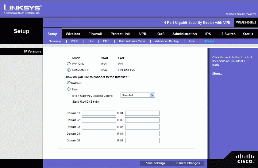
IP Mode
IPv4 Only. Select this option to use IPv4 on the Internet and local network.
Dual-Stack IP. Select this option to use IPv4 on the Internet and IPv4 and IPv6 on the
local network. Then select how the IPv6 hosts will connect to the Internet:
• NAPT-PT This allows an IPv6-only host on your LAN to connect to IPv4-only hosts on the WAN
using address translation and protocol-translation (per RFC2766).
• 6to4 This allows your IPv6 network to connect to other IPv6 networks via tunnels through IPv4 (per
RFC3056). The remote router also needs to support 6to4 as well. Since the tunnel can be
automatically formed based on traffic, there is no limit on how many tunnels you can have.
6to4 Gateway Access Control By default, this route allows 6to4 connections to or from any other
6to4 gateway. By enabling this Access Control, you can have a better control which IPv6 clouds this
router is connecting to. A list of IP addresses can be entered in the Access List. Those should be the
IPv4 addresses of the remote 6to4 gateways.
• Permit following sites: Allow only a limited set of 6to4 gateways to establish tunnel with our
router. Up to 20 sites can be configured and they can send traffic simultaneously.
• Block following sites: Prevent a limited set of 6to4 gateways from establishing tunnels with our
router. Up to 20 sites can be configured.
Static 6to4 DNS entry: Allow users to configure static DNS entry to map hostname to IPv6 address.
This will provide a convenient way for users to access remote IPv6 hosts.
Click the Save Settings button to save the network settings or click the Cancel Changes
button to undo your changes. Help information is displayed on the right-hand side of the
screen, and click More for additional details.
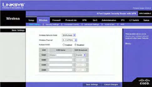
Wireless Tab
Basic Settings
Change the basic wireless network settings on this screen.
Basic Settings
Configure the basic Wireless Network attributes for this Wireless Router.
Wireless Network Mode. Select one of the following modes. The default is B/G/N-Mixed.
B-Only: All the wireless client devices can be connected to the Wireless Router at Wireless-B data
rates with a maximum speed of 11Mbps.
G-Only: Both Wireless-N and Wireless-G client devices can be connected at Wireless-G data rates
with a maximum speed of 54Mbps. Wireless-B clients cannot be connected in this mode.
N-Only: Only Wireless-N client devices can be connected at Wireless-N data rates with a maximum
speed of 300Mbps.
B/G-Mixed: Both Wireless-B and Wireless-G client devices can be connected at their respective data
rates. Wireless-N devices can be connected at Wireless-G data rates.
G/N-Mixed: Both Wireless-G and Wireless-N client devices can be connected at their respective data
rates. Wireless-B clients cannot be connected in this mode.
B/G/N-Mixed: All the wireless client devices can be connected at their respective data rates in this
mixed mode.
Disabled: To disable wireless connectivity completely. This might be useful during system
maintenance.
Wireless Channel. Select the appropriate channel to be used between your Wireless
Router and your client devices. The default is channel 6. You can also select Auto so that
your Wireless Router will select the channel with the lowest amount of wireless
interference while the system is booting up. Auto channel selection will start when you
click the Save Settings button, and it will take several seconds to scan through all the
channels to find the best channel. For the Wireless-N 40MHz channel option (see
Wireless - Advanced Wireless Settings Tab), the Wireless Router will automatically select
the adjacent 20MHz channel to combine them into a wider channel.
Multiple BSSID. Select Enabled or Disabled as required.
SSID Name. The SSID is the unique name shared between all devices in a wireless
network. It is case-sensitive, must not exceed 32 alphanumeric characters, and may be
any keyboard character. Make sure this setting is the same for all devices in your wireless
network. The default SSID name is linksys-n.
SSID Broadcast. This option allows the SSID to be broadcast on your network. You may
want to enable this function while configuring your network, but make sure that you
disable it when you are finished. With this enabled, someone could easily obtain the SSID
information with site survey software or Windows XP and gain unauthorized access to
your network. Click Enabled to broadcast the SSID to all wireless devices in range.
Click Disabled to increase network security and prevent the SSID from being seen on
networked PCs. The default is Enabled in order to help users configure their network
before use.
Change these settings as described here and click Save Settings to apply your changes, or
click Cancel Changes to cancel your changes. Help information is displayed on the
right-hand side of the screen, and click More for additional details.
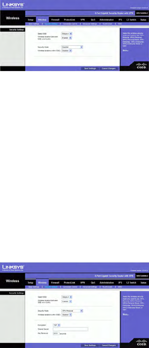
Wireless Security
Change the Wireless Router’s wireless security settings on this screen.
Wireless Security
Security Mode. Select the wireless security mode you want to use, WPA-Personal,
WPA2-Personal, WPA2-Personal Mixed, WPA-Enterprise, WPA2-Enterprise,
WPA2-Enterprise Mixed, or WEP. (WPA stands for Wi-Fi Protected Access, which is a
security standard stronger than WEP encryption and forward compatible with IEEE
802.11e. WEP stands for Wired Equivalent Privacy, Enterprise refers to using RADIUS
server for authentication, while RADIUS stands for Remote Authentication Dial-In User
Service.) Refer to the appropriate instructions below after you select the Authentication
Type and SSID Interoperability settings. To disable wireless security completely, select
Disabled. The default is Disabled.
Wireless Isolation (between SSID w/o VLAN). When disabled, wireless PCs that are
associated to the same network name (SSID), can see and transfer files between each
other. By enabling this feature, Wireless PCs will not be able to see each other. This
feature is very useful when setting up a wireless hotspot location.
The following section describes the detailed options for each Security Mode.
Disabled
To disable wireless security completely, select Disabled.
WPA-Personal (also known as WPA-PSK)
Encryption. WPA offers you two encryption methods, TKIP and AES for data encryption.
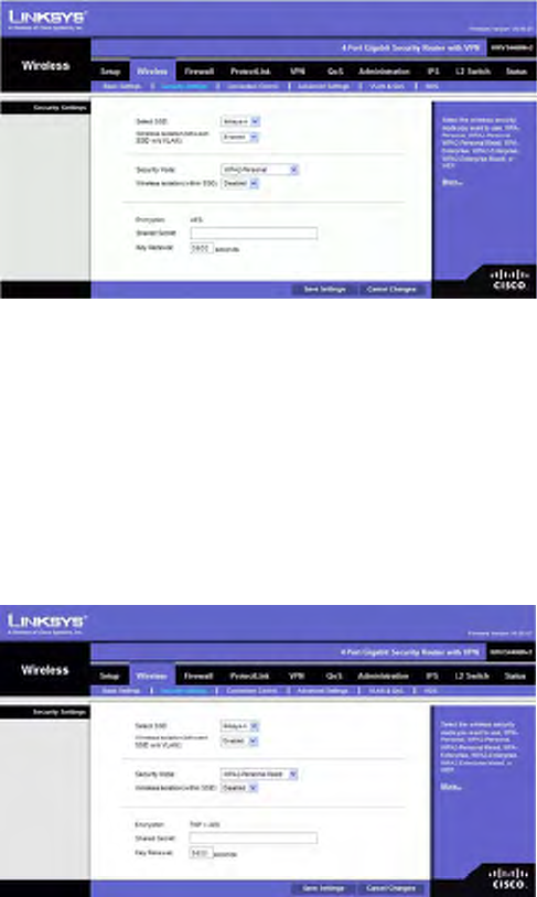
Select the type of algorithm you want to use, TKIP or AES. The default is TKIP.
Shared Secret. Enter a WPA Shared Key of 8-63 characters.
Key Renewal. Enter a Key Renewal Timeout period, which instructs the Wireless Router
how often it should change the encryption keys. The default is 3600 seconds.
WPA2-Personal
Encryption. WPA2 always uses AES for data encryption.
Shared Secret. Enter a WPA Shared Key of 8-63 characters.
Key Renewal. Enter a Key Renewal Timeout period, which instructs the Wireless Router
how often it should change the encryption keys. The default is 3600 seconds.
WPA2-Personal Mixed
This security mode supports the transition from WPA-Personal to WPA2-Personal. You
can have client devices that use either WPA-Personal or WPA2-Personal. The Wireless
Router will automatically choose the encryption algorithm used by each client device.
Encryption. Mixed Mode automatically chooses TKIP or AES for data encryption.
Shared Secret. Enter a WPA Shared Key of 8-63 characters.
Key Renewal. Enter a Key Renewal Timeout period, which instructs the Wireless Router
how often it should change the encryption keys. The default is 3600 seconds.
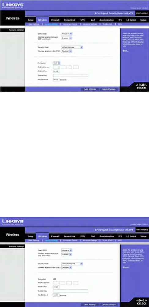
WPA-Enterprise
This option features WPA used in coordination with a RADIUS server for client
authentication. (This should only be used when a RADIUS server is connected to the
Wireless Router.)
Encryption. WPA offers you two encryption methods, TKIP and AES for data encryption.
Select the type of algorithm you want to use, TKIP or AES. The default is TKIP.
RADIUS Server. Enter the RADIUS server’s IP address.
RADIUS Port. Enter the port number used by the RADIUS server. The default is 1812.
Shared Key. Enter the Shared Secret key used by the Wireless Router and RADIUS
server.
Key Renewal. Enter a Key Renewal Timeout period, which instructs the Wireless Router
how often it should change the encryption keys. The default is 3600 seconds.
WPA2-Enterprise
This option features WPA2 used in coordination with a RADIUS server for client
authentication. (This should only be used when a RADIUS server is connected to the
Wireless Router.)
Encryption. WPA2 always uses AES for data encryption.
RADIUS Server. Enter the RADIUS server’s IP address.
RADIUS Port. Enter the port number used by the RADIUS server. The default is 1812.
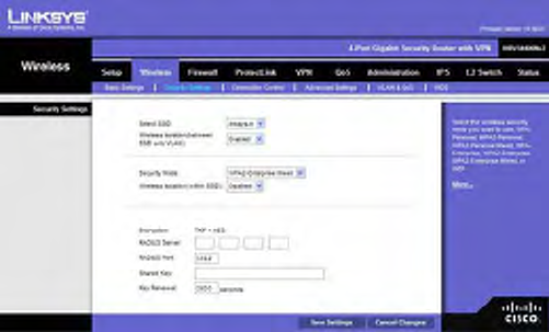
Shared Key. Enter the Shared Secret key used by the Wireless Router and RADIUS
server.
Key Renewal. Enter a Key Renewal Timeout period, which instructs the Wireless Router
how often it should change the encryption keys. The default is 3600 seconds.
WPA2-Enterprise Mixed
This security mode supports the transition from WPA-Enterprise to WPA2-Enterprise.
You can have client devices that use either WPA-Enterprise or WPA2-Enterprise. The
Wireless Router will automatically choose the encryption algorithm used by each client
device.
Encryption. Mixed Mode automatically chooses TKIP or AES for data encryption.
RADIUS Server. Enter the RADIUS server’s IP address.
RADIUS Port. Enter the port number used by the RADIUS server. The default is 1812.
Shared Key. Enter the Shared key used by the Wireless Router and RADIUS server.
Key Renewal. Enter a Key Renewal Timeout period, which instructs the Wireless Router
how often it should change the encryption keys. The default is 3600 seconds.
WEP
This security mode is defined in the original IEEE 802.11. This mode is not
recommended now due to its weak security protection. Users are urged to migrate to
WPA or WPA2.
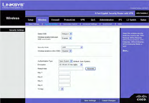
Authentication Type. Choose the 802.11 authentication type as either Open System or
Shared Key. The default is Open System.
WEP Encryption. Select a level of WEP encryption, 40/64 bits (10 hex digits) or
104/128 bits (26 hex digits).
Passphrase. If you want to generate WEP keys using a Passphrase, then enter the
Passphrase in the field
provided and click the Generate key.
Key 1-4. If you want to manually enter WEP keys, then complete the fields provided.
Each WEP key can consist of the letters “A” through “F” and the numbers “0” through
“9”. It should be 10 characters in length for 64-bit encryption or 26 characters in length
for 128-bit encryption.
Tx Key. Select one of the keys to be used for data encryption (when you manually enter
multiple WEP keys).
Change these settings as described here and click Save Settings to apply your changes, or
click Cancel Changes to cancel your changes. Help information is displayed on the
right-hand side of the screen, and click More for additional details.
Connection Control
This screen allows you to configure the Connection Control List to either permit or block
specific wireless client devices connecting to (associating with) the Wireless Router.
Wireless Connection Control
Select SSID. Select the desired SSID.
Enabled/Disabled. Enable or disable wireless connection control. The default is
Disabled.
Connection Control
There are two ways to control the connection (association) of wireless client devices. You
can either prevent specific devices from connecting to the Wireless Router, or you can
allow only specific client devices to connect to the Wireless Router. The client devices
are specified by their MAC addresses. The default is to allow only specific client devices.
Wireless Client List
Instead of manually entering the MAC addresses of each client, the Wireless Router
provides a convenient way to select a specific client device from the client association
table. Click this button and a window appears to let you select a MAC address from the
table. The selected MAC address will be entered into the Connection Control List.
Connection Control List
MAC 01-20. Enter the MAC addresses of the wireless client devices you want to control.
Change these settings as described here and click Save Settings to apply your changes, or
click Cancel Changes to cancel your changes. Help information is displayed on the
right-hand side of the screen.
Advanced Wireless Settings
This screen allows you to configure the advanced settings for the Wireless Router. The
Wireless-N Router adopts several new parameters to adjust the channel bandwidth and
guard intervals to improve the data rate dynamically. Linksys recommends to let your
Wireless Router automatically adjust the parameters for maximum data throughput.
Advanced Settings
You can change the following advanced parameters (some only for Wireless-N) for this
Wireless Router.
Channel Bandwidth. You can select the channel bandwidth manually for Wireless-N
connections. When it is set to 20MHz, only the 20MHz channel is used. When it is set to
40MHz, Wireless-N connections will use 40MHz channel but Wireless-B and Wireless-G
will still use 20MHz channel. When it is set to Auto, it allows wireless clients to negotiate
the bandwidth to use. The default is 20MHz.
Guard Interval. You can select the guard interval manually for Wireless-N connections.
The two options are Short (400ns) and Long (800ns). The default is Auto.
CTS Protection Mode. CTS (Clear-To-Send) Protection Mode function boosts the
Wireless Router’s ability to catch all wireless transmissions, but will severely decrease
performance. Keep the default setting, Auto, so the Wireless Router can use this feature
as needed, when the Wireless-N/G products are not able to transmit to the Wireless
Router in an environment with heavy 802.11b traffic. Select Disabled if you want to
permanently disable this feature.
Beacon Interval. This value indicates the frequency interval of the beacon. A beacon is
a packet broadcast by the Wireless Router to keep the network synchronized. A beacon
includes the wireless networks service area, the Wireless Router address, the Broadcast
destination addresses, a time stamp, Delivery Traffic Indicator Maps, and the Traffic
Indicator Message (TIM). The default is 100 ms.
DTIM Interval. This value indicates how often the Wireless Router sends out a Delivery
Traffic Indication Message (DTIM). Lower settings result in more efficient networking,
while preventing your PC from dropping into power-saving sleep mode. Higher settings
allow your PC to enter sleep mode, thus saving power, but interferes with wireless
transmissions. The default is 1 ms.
RTS Threshold. This setting determines how large a packet can be before the Wireless
Router coordinates transmission and reception to ensure efficient communication. This
value should remain at its default setting of 2346. If you encounter inconsistent data flow,
only minor modifications are recommended.
Change these settings as described here and click Save Settings to apply your changes, or
click Cancel Changes to cancel your changes. Help information is displayed on the
right-hand side of the screen, and click More for additional details.
VLAN & QoS
This screen allows you to configure the Qos and VLAN settings for the Access Point. The
QoS (Quality of Service) feature allows you specify priorities for different traffic. Lower
priority traffic will be slowed down to allow greater throughput or less delay for high
priority traffic. The 802.1Q VLAN feature is allowing traffic from different sources to be
segmented. Combined with the multiple SSID feature, this provides a powerful tool to
control access to your LAN
VLAN
Enabled/Disabled VLAN. You can enabled this feature only if the hubs/switches on your
LAN support the VLAN standard.
AP Management VLAN. Define the VLAN ID used for management.
VLAN ID. Enter the VLAN ID.
QoS
U-APSD(WMM Power Save). Select Enabled or Disabled as required.
WMM. Wi-Fi Multimedia is a QoS feature defined by WiFi Alliance before IEEE
802.11e was finalized. Now it is part of IEEE 802.11e. When it is enabled, it provides
four priority queues for different types of traffic. It automatically maps the incoming
packets to the appropriate queues based on QoS settings (in IP or layer 2 header). WMM
provides the capability to prioritize traffic in your environment. The default is Enabled.
Change these settings as described here and click Save Settings to apply your changes, or
click Cancel Changes to cancel your changes. Help information is displayed on the
right-hand side of the screen.
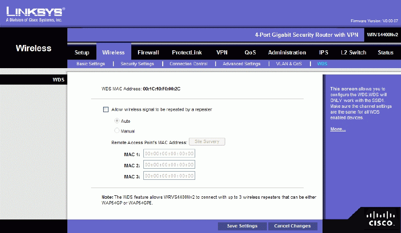
WDS
On this screen you can configure the WDS (Wireless Distribution System) settings for the
device.
WDS MAC Address. It displays the read-only MAC address for the WDS.
Allow wireless signal to be repeated by a repeater. Select Auto or Manual as required.
Remote Access Point’s MAC Address. You can either enter the MAC address directly,
or, if the other AP is on-line, you can click the Site Survey button and select from a list
of available APs.
Change these settings as described here and click Save Settings to apply your changes, or
click Cancel Changes to cancel your changes. Help information is displayed on the
right-hand side of the screen.
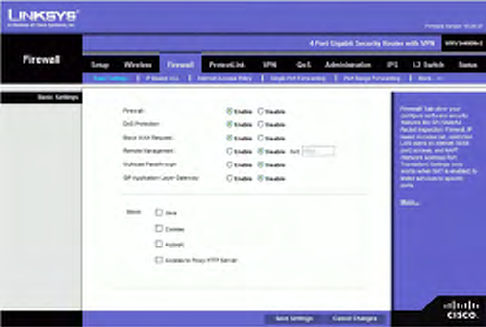
Firewall
The Firewall Tab allows you to configure software security features like SPI (Stateful
Packet Inspection) Firewall, IP based Access List, restriction LAN users on Internet
(WAN port) access, and NAPT (Network Address Port Translation) Settings (only works
when NAT is enabled) to limited services to specific ports.
Note that for WAN traffic, NAPT settings are applied first, then it will pass the SPI
Firewall settings, followed by IP based Access List (which requires more CPU power).
Basic Settings
Firewall: SPI (Stateful Packet Inspection) Firewall, when you enable this feature, the
Router will perform deep packet inspection on all the traffic going through the Router
and drop the packets that do not follow the pre-defined protocol behavior. The default is
Enable.
DoS Protection: When enabled, the Router will prevent DoS (Denial of Service) attacks
coming in from the Internet. DOS attacks are making your Router’s CPU busy such that
it cannot provide services to regular traffic. The default Is Enable.
Block WAN Request: When enabled, the Router will ignore PING Request from the
Internet so it seems to be hidden. The default is Enable.
Remote Management: When enabled, the Router will allow the Web-based Utility to be
accessed from the Internet. The default is Disable.
Multicast Pass-through: When enabled, the Router will allow IP Multicast traffic to
come in from the Internet. The default is Disable.
SIP Application Layer Gateway When this feature is enabled, the SIP Application
Layer Gateway (ALG) allows Session Initiation Protocol (SIP) packets (used for Voice
over IP) to traverse the NAT firewall. This feature can be disabled if the VoIP service
provider is using other NAT traversal solutions such as STUN, TURN, and ICE.
Block. Select the Web features that you wish to restrict. All those features could place
security concern to your PCs on the LAN side. You have to balance your needs on those
applications and security. The default is unselected.
• Java: Java is a programming language for websites. If you deny Java, you run the risk of not
having access to Internet sites created using this programming language.
• Cookies: A cookie is data stored on your PC and used by Internet sites when you interact with
them, so you may not want to deny cookies.
• ActiveX: ActiveX is a Microsoft (Internet Explorer) programming language for websites. If you
deny ActiveX, you run the risk of not having access to Internet sites using this programming
language. Also, Windows Update uses ActiveX, so if this is blocked, Windows update will not
work.
• Access to Proxy HTTP Server: If local users have access to WAN proxy servers, they may be
able to circumvent the Router’s content filters and access Internet sites blocked by the Router.
Denying Proxy will block access to any WAN proxy servers.
Change these settings as described here and click Save Settings to apply your changes, or
click Cancel Changes to cancel your changes. Help information is displayed on the
right-hand side of the screen, and click More for additional details.
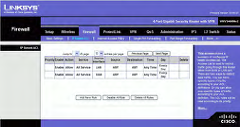
IP Based ACL
This screen shows a summary of configured IP based Access List. The Access List is used
to restrict traffic going through the Router either from WAN or LAN port. There are two
ways to restrict data traffic. You can block specific types of traffic according to your ACL
definitions. Or you can allow only specific types of traffic according to your ACL
definition. The ACL rules will be read according to its priority. If there is a match for a
packet, the action will be taken and following lower priority rules will not be checked
against this packet.
Note that the higher the number of rules that need to be checked against packets, the
lower the throughput. Use ACL rules with caution.
There are two default rules in the table that cannot be deleted. The first rule will allow all
traffic coming in from LAN port to pass the Router. The second rule will allow all traffic
coming in from WAN port. These two rules have the lowest priority, so without adding
any user defined rules, all the packets can be passed through from both WAN and LAN
sides.
The rule will be enabled when the Enable button is checked, and when Date and Time are
matched. If any of conditions are not met, the rule will not be used to check against
packets.
The following are descriptions on each of the fields in the ACL Table:
Page Selections: You can select specific page of ACL list from the drop-down menu to
be displayed. Or you can navigate them page by page through Previous Page and Next
Page button.
Priority: This defines the order on which rule is checked against first. The smaller
number has higher priority. The default rules will always be checked last.
Enable: This tells the Router if the rule is active or not. You can have rules defined in the
ACL Table but in an inactive state. The administrator can decide on when to enable
specific ACL rules manually.
Action: This defines how the rule is to affect the traffic. It can be either Allow or Deny.
If the rule is matched and the action is Allow, the packet will be forwarded. If the rule is
matched and the action is Deny, the packet will be dropped.
Service: This is the service(s) to which the rule applies.
Source Interface: Select LAN, WAN, or ANY interface.
Source: This is the source IP address, which can be one specific IP address, ANY (all IP
addresses), a range of IP addresses, or a specific IP subnet.
Destination: This is the destination IP address, which can be one specific IP address,
ANY (all IP addresses), a range of IP addresses, or a specific IP subnet.
Time: Displays the time period this rule will be enabled (used together with Date). It can
be set to Any Time.
Day: Displays the days in a week this rule will be enabled (used together with Time). It
can be set to Every Day.
Edit button: Use this button to go to Edit IP ACL Rule screen and modify this rule.
Delete button: Use this button to delete the ACL rule from the list.
To add a new rule to the ACL rule table, click Add New Rule and the Edit IP ACL Rule
screen appears. Follow the instructions in the section below to create a new ACL rule. To
disable all the rules without deleting them, click Disable All Rules. To delete all the rules
from the table, click Delete All Rules.
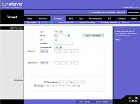
Edit IP ACL Rule
This Web page can be entered only through IP Based ACL Tab. You can enter this page
by clicking Add New Rule button on that page.
New Rule
Action: Select either Allow or Deny. Default is Allow.
Service: Select ALL or pre-defined (or user-defined) services from the drop-down menu.
Log Select this option to log all traffic that is filtered by this rule.
Log Prefix: This string will be attached in front of the log for the matched event.
Source Interface: Select LAN, WAN, or ANY interface.
Source: To apply the rule to one source IP address, select Single from the drop-down
menu, then enter the address in the field. To apply the rule to all source IP addresses,
select ANY from the drop-down menu. To apply the rule to a range of IP addresses, select
Range and enter the starting and ending IP addresses. To apply the rule to a subnet, select
Net and enter the IP address and subnet mask.
Destination: To apply the rule to one destination IP address, select Single from the
drop-down menu, then enter the address in the field. To apply the rule to all destination IP
addresses, select ANY from the drop-down menu. To apply the rule to a range of IP
addresses, select Range and enter the starting and ending IP addresses. To apply the rule
to a subnet, select Net and enter the IP address and subnet mask.
Service Management Button: Click this button and the Service Tab to add new service
type to the Service drop-down menu.
Scheduling
Time: To make the rule apply for an entire day, select Every time. To make the rule
apply only during a specific period of the day, enter the starting time in the From field
and the ending time in the To field.
Date: To make the rule apply on a daily basis, select Everyday. To make the rule apply
on specific days of the week only, select the desired days.
Change these settings as described here and click Save Settings to apply your changes, or
click Cancel Changes to cancel your changes. Help information is displayed on the
right-hand side of the screen, and click More for additional details.
Internet Access Policy
Access to the Internet can be managed by policies. A policy consists of four components.
You need to define the PCs (MAC or IP address) to apply this policy, either Deny or
Allow Internet service, what time and date to enable this policy, and what URLs or
Keywords to apply this policy.
Use the settings on this screen to establish an access policy. Selecting a policy from the
drop-down menu will display that policy's settings. You can then perform the following
operations:
• Create a Policy - see instructions below.
• Delete the current policy - click the Delete button.
• View all policies - click the Summary button. On the Summary screen, the policies are listed with
the following information: No., Policy Name, Days, Time, and a checkbox to delete (clear) the
policy. To delete a policy, check the checkbox in the Delete column, and click the Delete button
• View or change the PCs covered by the current policy - click the Edit List of PCs button.
On the List of PCs screen, you can define PCs by MAC Address or IP Address. You can
also enter a range of IP Addresses if you want this policy to affect a group of PCs.
To create an Internet Access policy:
1. Select the desired policy number from the Internet Access Policy drop-down menu.
2. Enter a Policy Name in the field provided.
3. To enable this policy, select the Enable option.
4. Click the Edit List of PCs button to select which PCs will be affected by the policy. The List of PCs
screen will appear in a sub-window. You can select a PC by MAC Address or IP Address. You can
also enter a range of IP Addresses if you want this policy to affect a group of PCs. After making your
changes, click the Save Settings button to apply your changes.
5. Click the appropriate option, Deny or Allow, depending on whether you want to block or allow
Internet access for the PCs you listed on the List of PCs screen.
6. Decide what Days and what Times you want this policy to be enforced. Select the individual days
during which the policy will be in effect, or select Everyday. Enter a range of hours and minutes
during which the policy will be in effect, or select 24 Hours.
7. If you wish to block access to Web sites, use the Website Blocking by URL Address or Website
Blocking by Keyword feature.
• Website Blocking by URL Address. Enter the URL or Domain Name of the web sites you wish
to block.
• Website Blocking by Keyword. Enter the keywords you wish to block in the fields provided. If
any of these Keywords appears in the URL of a web site, access to the site will be blocked. Note
that only the URL is checked, not the content of each Web page.
8. Click the Save Settings button to save the policy settings. Click Cancel Changes to cancel any
changes you have entered.
Single Port Forwarding
This is one of the NAPT (Network Address Port Translation) feature. Use the Single Port
Forwarding screen when you want to open specific services (that use single port). This
allows users on the Internet to access this server by using the WAN port address and the
matched external port number. When users send these types of request to your WAN port
IP address via the Internet, the NAT Router will forward those requests to the appropriate
servers on your LAN.
Application. Enter the name of the application you wish to configure.
External Port. This is the port number used by the service or Internet application.
Internet users must connect using this port number. Check with the software
documentation of the Internet application for more information.
Internal Port. This is the port number used by the Router when forwarding Internet
traffic to the PC or server on your LAN and is usually the same as the External Port
number. If it is different, the Router performs a Port Translation, so that the port number
used by Internet users is different from the port number used by the server or Internet
application.
For example, you could configure your Web Server to accept connections on both port 80
(standard) and port 8080. Then, enable Port Forwarding, set the External Port to 80 and
the Internal Port to 8080. Now, any traffic from the Internet to your Web server will be
using port 8080, even though the Internet users used the standard port, 80. (Users on the
local LAN can and should connect to your Web Server using the standard port 80.)
Protocol. Select the protocol used for this application, TCP or UDP.
IP Address. For each application, enter the IP address of the PC running the specific
server application.
Enabled. Select Enabled to enable port forwarding for the relevant server application.
Change these settings as described here and click Save Settings to apply your changes, or
click Cancel Changes to cancel your changes. Help information is displayed on the
right-hand side of the screen, and click More for additional details.
Port Range Forwarding
This is one of the NAPT (Network Address Port Translation) features. The Port Range
Forwarding screen allows you to set up public services on your network, such as web
servers, ftp servers, e-mail servers, or other specialized Internet applications that use one
or multiple port numbers (e.g. video conference). The port numbers being used will not
change while forwarding to the local network. This allows users on the Internet to access
this server by using the WAN port IP address and the pre-defined port numbers. When
users send these types of requests to your WAN port IP address via the Internet, the NAT
Router will forward those requests to the appropriate servers on your LAN.
Application. Enter the name of the application you wish to configure.
Start. This is the beginning of the port range. Enter the beginning of the range of port
numbers (external ports)
used by the server or Internet application. Check with the software documentation of the
Internet application for more information if necessary.
End. This is the end of the port range. Enter the end of the range of port numbers
(external ports) used by the server or Internet application. Check with the software
documentation of the Internet application for more information if necessary.
Protocol. Select the protocol(s) used for this application, TCP and/or UDP.
IP Address. For each application, enter the IP address of the PC running the specific
application.
Enabled. Select Enabled to enable port range forwarding for the relevant application.
Change these settings as described here and click Save Settings to apply your changes, or
click Cancel Changes to cancel your changes. Help information is displayed on the
right-hand side of the screen, and click More for additional details.
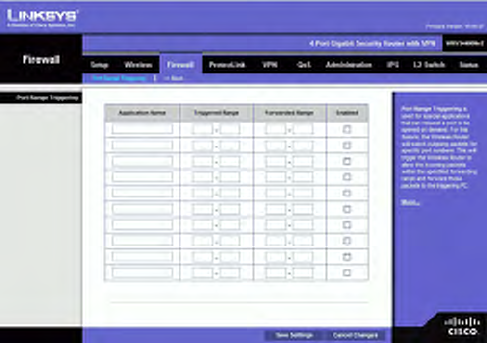
Port Range Triggering
This is one of the NAPT (Network Address Port Translation) feature. Port Range
Triggering is used for special applications that can request a port to be opened on demand.
For this feature, the Wireless Router will watch outgoing packets for specific port
numbers. This will trigger the Wireless Router to allow the incoming packets within the
specified forwarding range and forward those packets to the triggering PC. One of the
example applications is QuickTime. It would use port 1000 for outgoing packets and
2000 for incoming packets.
Application. Enter the name of the application you wish to configure.
Triggered Range. For each application, list the triggered port number range. These are
the ports used by outgoing traffic. Check with the Internet application documentation for
the port number(s) needed. In the first field, enter the starting port number of the
Triggered Range. In the second field, enter the ending port number of the Triggered
Range.
Forwarded Range. For each application, list the forwarded port number range. These are
the ports used by incoming traffic. Check with the Internet application documentation for
the port number(s) needed. In the first field, enter the starting port number of the
Forwarded Range. In the second field, enter the ending port number of the Forwarded
Range.
Enabled. Select Enabled to enable port range triggering for the relevant application.
Change these settings as described here and click Save Settings to apply your changes, or
click Cancel Changes to cancel your changes. Help information is displayed on the
right-hand side of the screen, and click More for additional details.
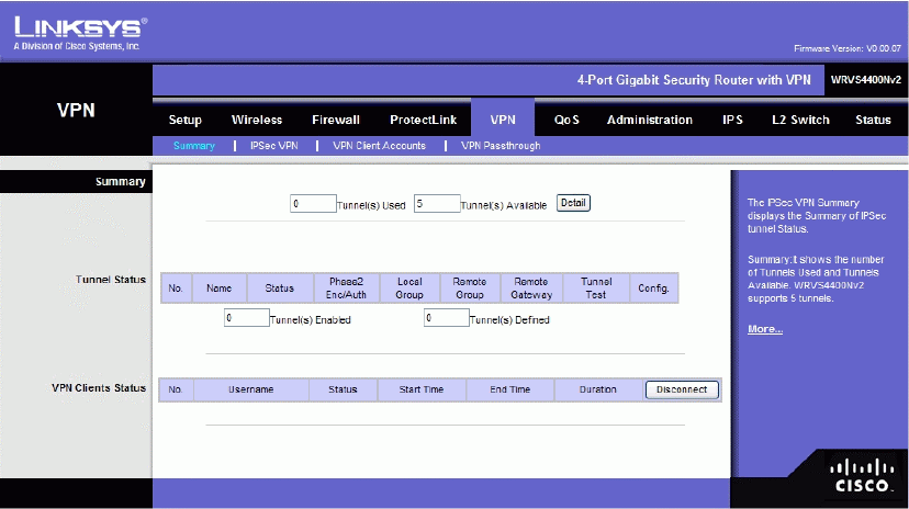
VPN Tab
Summary
Tunnels Used Displays the number of tunnels used.
Tunnel(s) Available Displays the number of available tunnels.
Detail button Click Detail to display more tunnel information.
Tunnel Status
No. Displays the number of the tunnel.
Name Displays the name of the tunnel, as defined by the Tunnel Name field on the VPN
> IPSec VPN screen.
Status Displays the tunnel’s status: Connected, Hostname Resolution Failed, Resolving
Hostname, or Waiting for Connection.
Phase Enc/Auth. Displays the Phase 2 Encryption type (3DES), Authentication type
(MD5 or SHA1), and Group (768-bit, 1024-bit, or 1536-bit) that you chose in the VPN >
IPSec VPN screen.
Local Group Displays the IP address and subnet of the local group.
Remote Group Displays the IP address and subnet of the remote group.
Remote Gateway Displays the IP address of the remote gateway.
Tunnel Test Click Connect to verify the tunnel status; the test result is updated in the
Status column. If the tunnel is connected, you can disconnect the IPSec VPN connection
by clicking Disconnect.
Config Click Edit to change the tunnel’s settings. Click Trash to delete all of the tunnel’s
settings.
Tunnel(s) Enabled Displays the total number of currently enabled tunnels.
Tunnel(s) Defined Displays the number of tunnels currently defined. This number will
be greater than the Tunnels Enabled field if any defined tunnels have been disabled.
VPN Clients Status
No. Displays the user number from 1 to 5.
Username. Displays the username of the VPN Client.
Status Displays the connection status of the VPN Client.
Start Time Displays the start time of the most recent VPN session for the specified VPN
Client.
End Time Displays the end time of a VPN session if the VPN Client has disconnected.
Duration Displays the total connection time of the latest VPN session.
Disconnect Check the Disconnect checkbox at the end of each row in the VPN Clients
Table and click the Disconnect button to disconnect a VPN Client session.