LINKSYS WRVS4400NV2 Wireless-N Gigabit Security Router with VPN User Manual
LINKSYS LLC Wireless-N Gigabit Security Router with VPN
UserManual.wiki
>
LINKSYS
>
WRVS4400NV2 User Manual
>
User manual 2 of 2
Contents
1.
User manual 1 of 2
2.
User manual 2 of 2
User manual 2 of 2
Navigation menu
Upload a User Manual
Namespaces
Wiki Guide
HTML
PDF
Info
Views
User Manual
Discussion / Help
Navigation


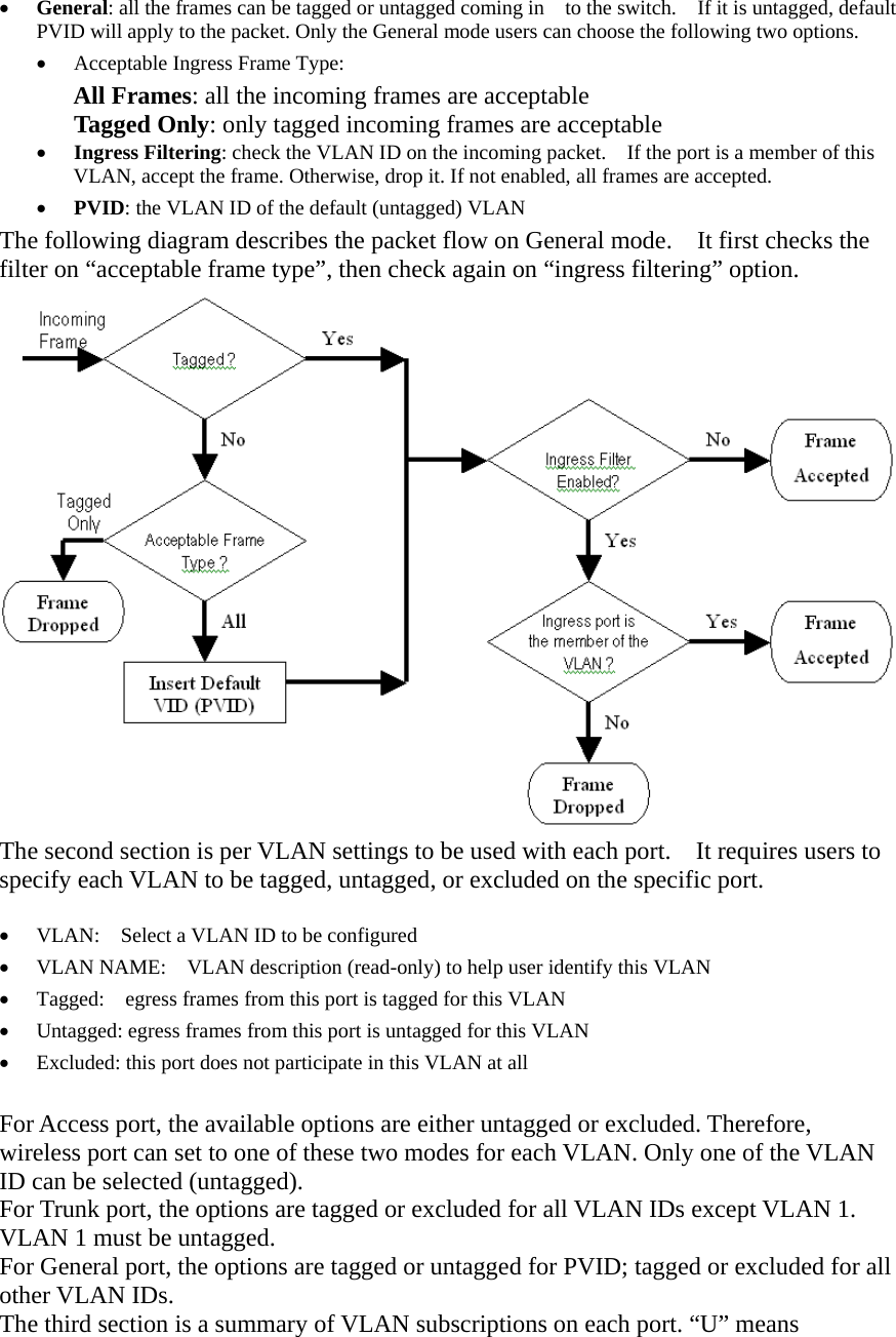
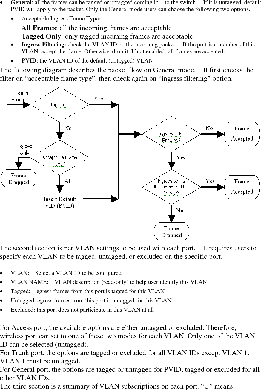
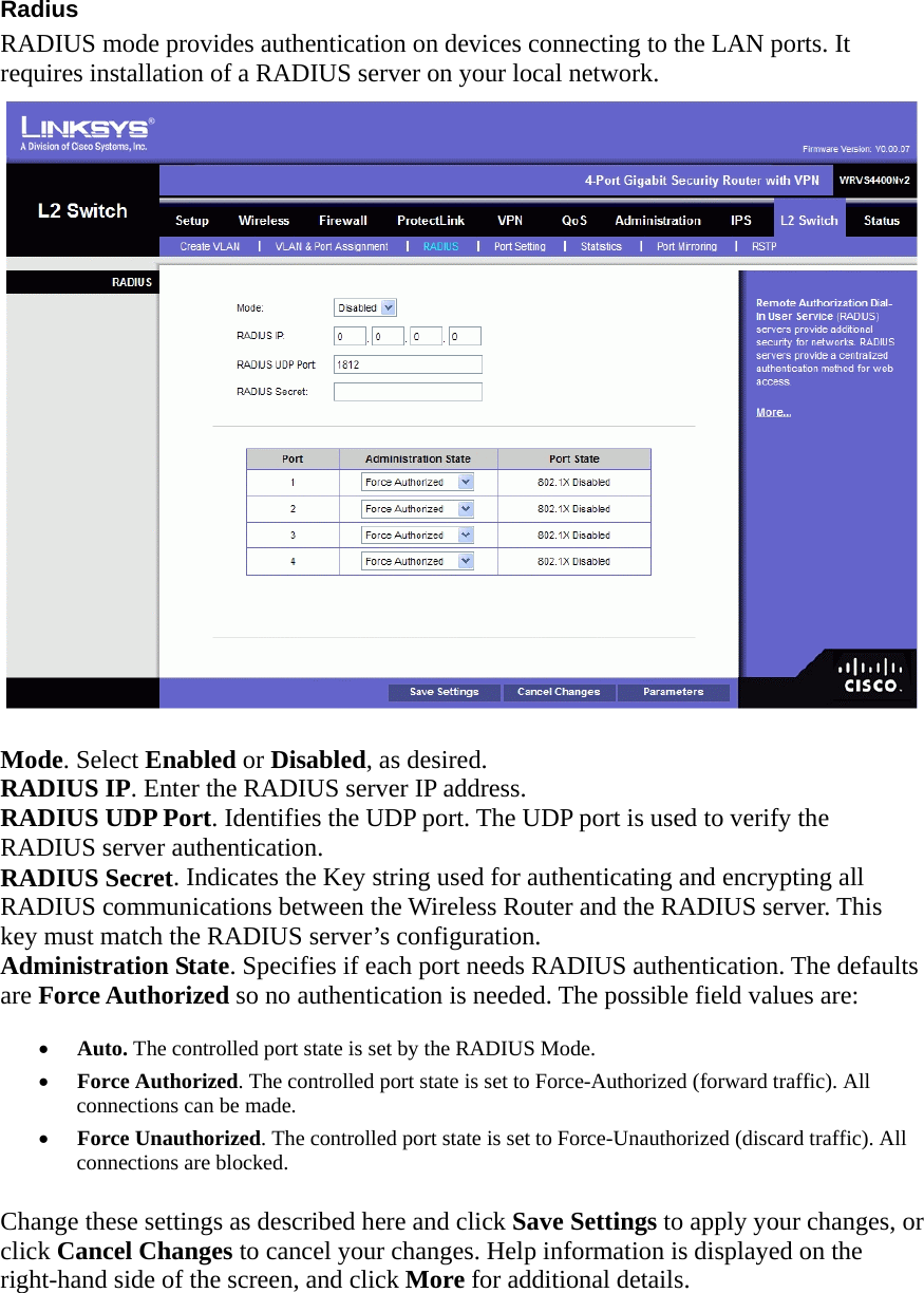
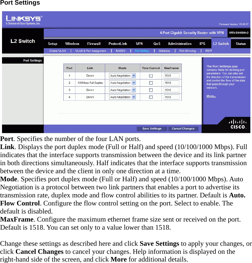
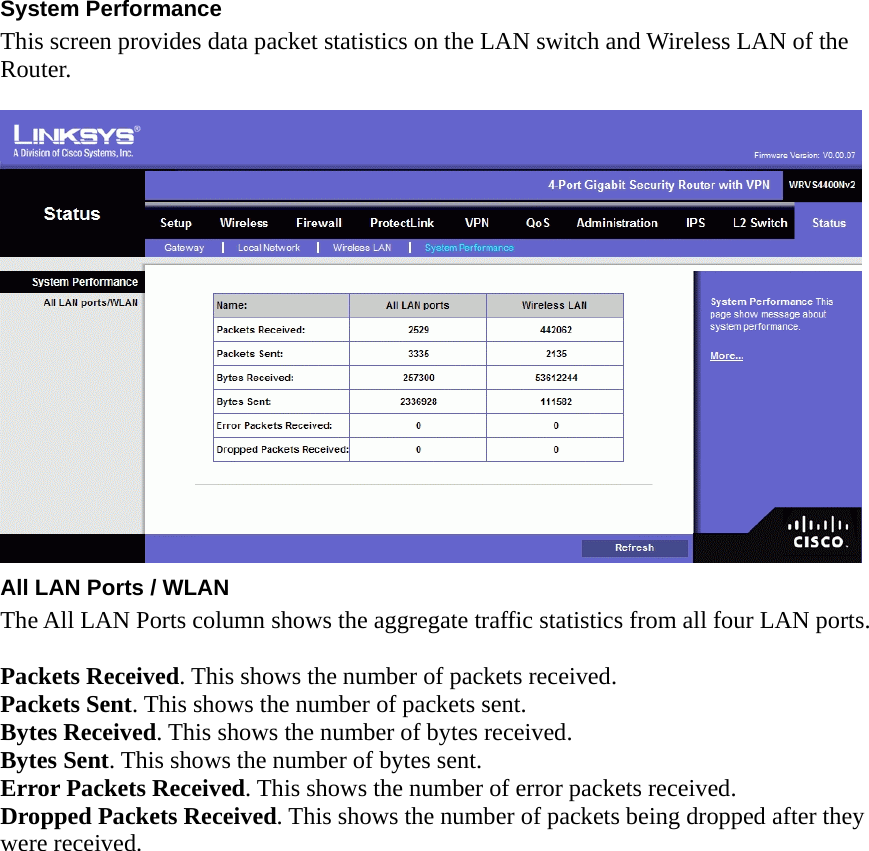
![18. I’m trying to access the Router’s Web-based Utility, but I do not see the login screen. Instead, I see a screen saying, “404 Forbidden.” If you are using Windows Explorer, perform the following steps until you see the Web-based Utility’s login screen (Netscape Navigator will require similar steps): A. Click File. Make sure Work Offline is NOT checked. B. Press CTRL + F5. This is a hard refresh, which will force Windows Explorer to load new webpages, not cached ones. C. Click Tools. Click Internet Options. Click the Security tab. Click the Default level button. Make sure the security level is Medium or lower. Then click the OK button. Frequently Asked Questions What is the maximum number of IP addresses that the Router will support? The Router will support up to 253 IP addresses if the subnetmask is set to 255.255.255.0. Is IPSec Passthrough supported by the Router? Yes, enable or disable IPSec Passthrough on the VPN => VPN Pass Through tab. Where is the Router installed on the network? In a typical environment, the Router is installed between the cable/DSL modem and the LAN. Plug the Router into the cable/DSL modem’s Ethernet port. Does the Router support IPX or AppleTalk? No. TCP/IP is the only protocol standard for the Internet and has become the global standard for communications. IPX, a NetWare communications protocol used only to route messages from one node to another, and AppleTalk, a communications protocol used on Apple and Macintosh networks, can be used for LAN to LAN connections, but those protocols cannot connect from the Internet to the LAN. What is Network Address Translation and what is it used for? Network Address Translation (NAT) translates multiple IP addresses on the private LAN to one public address that is sent out to the Internet. This adds a level of security since the address of a PC connected to the private LAN is never transmitted on the Internet. Furthermore, NAT allows the Router to be used with low cost Internet accounts, such as DSL or cable modems, when only one TCP/IP address is provided by the ISP. The user may have many private addresses behind this single address provided by the ISP. Does the Router support any operating system other than Windows 98, Millennium, 2000, or XP? Yes, but Linksys does not, at this time, provide technical support for setup, configuration or troubleshooting of any non-Windows operating systems. I set up an Unreal Tournament Server, but others on the LAN cannot join. What do I need to do? If you have a dedicated Unreal Tournament server running, you need to create a static IP for each of the LAN computers and forward ports 7777, 7778, 7779, 7780, 7781, and 27900 to the IP address of the server. You can also use a port forwarding range of 7777 to 27900. If you want to use the UT Server Admin, forward another port (8080 usually works well but is used for remote admin. You may have to disable this.), and then in the [UWeb.WebServer] section of the server.ini file, set the ListenPort to 8080 (to match the](https://usermanual.wiki/LINKSYS/WRVS4400NV2.User-manual-2-of-2/User-Guide-967977-Page-50.png)