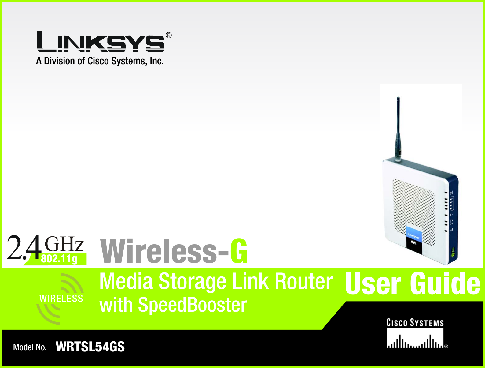
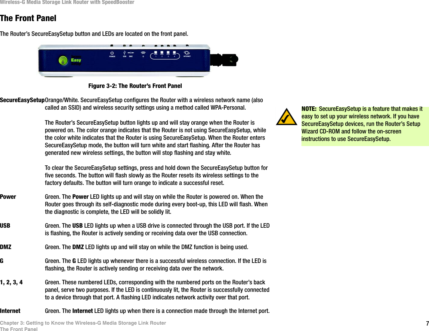
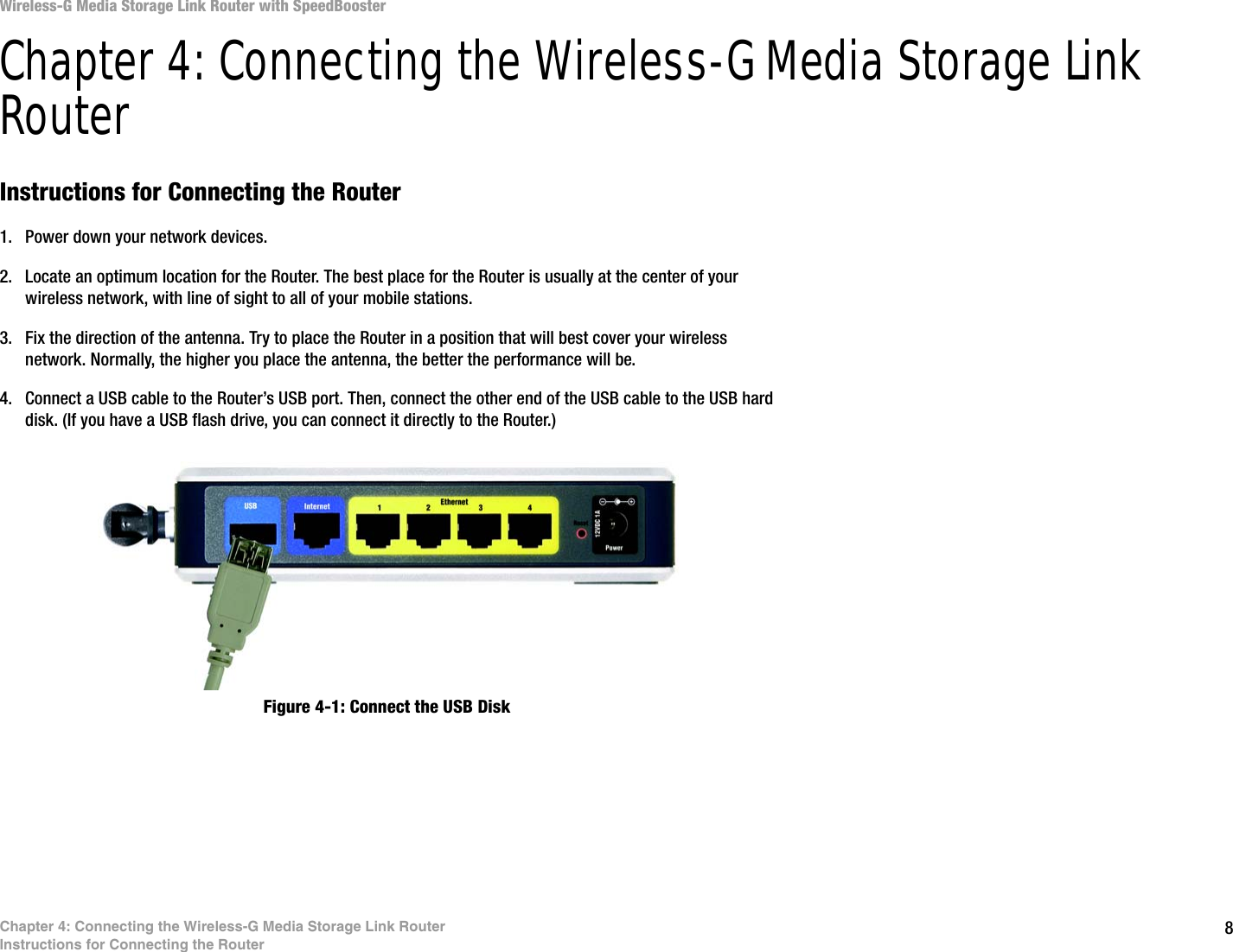
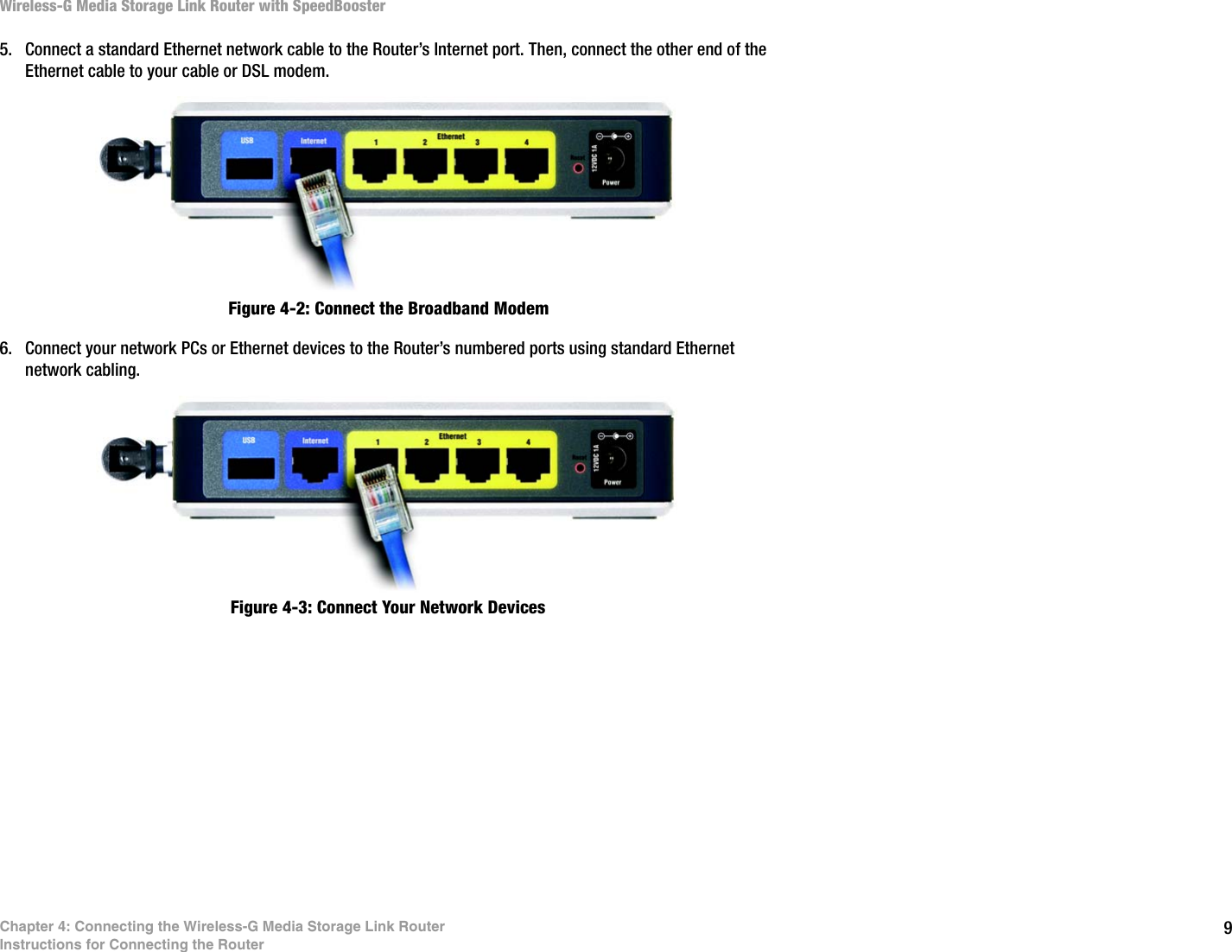
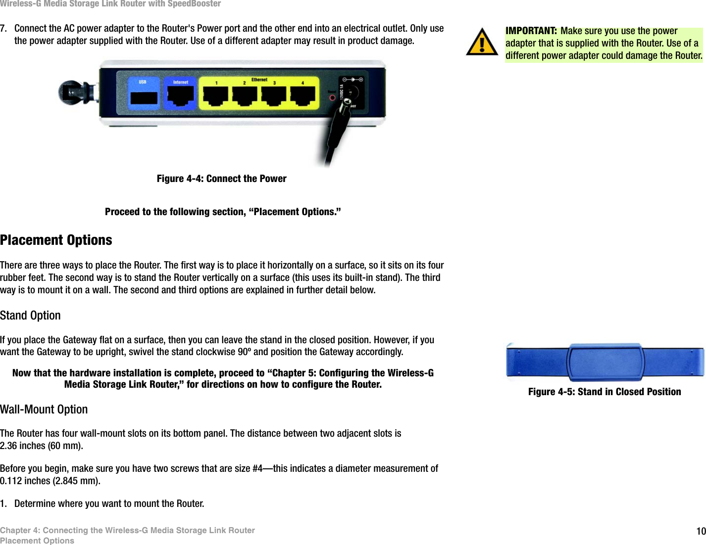
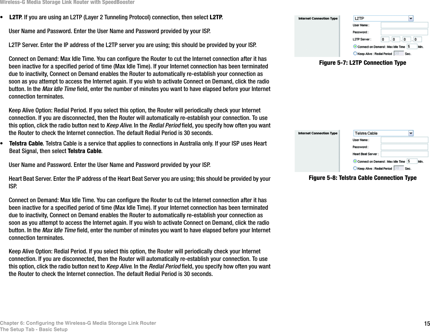
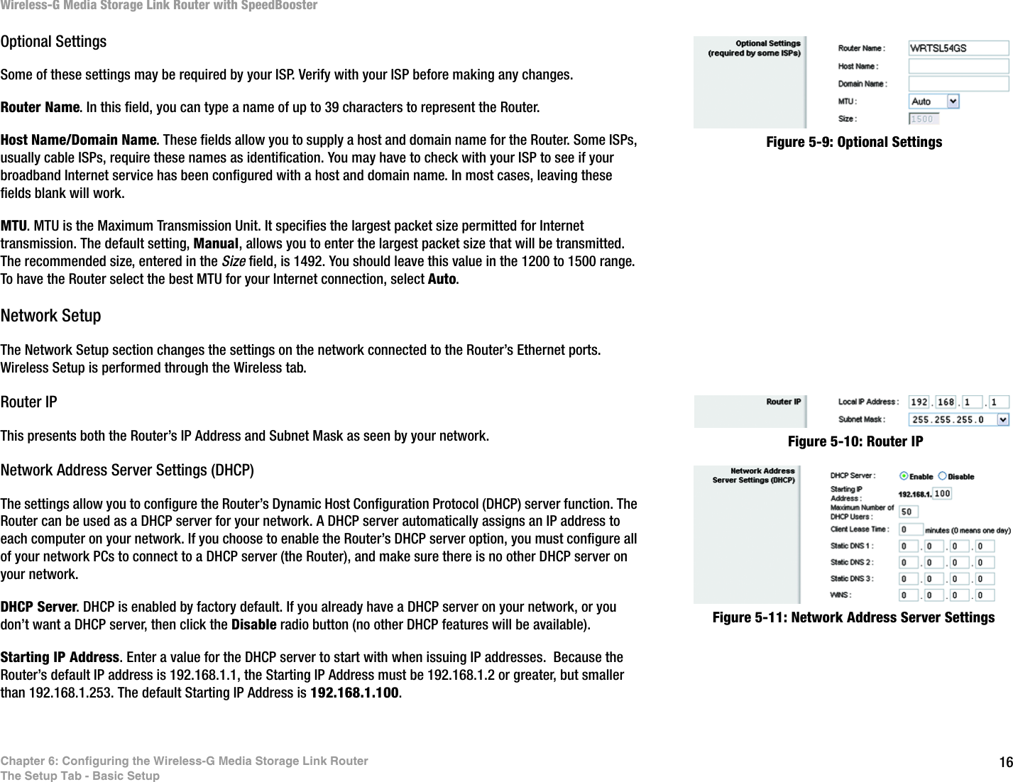
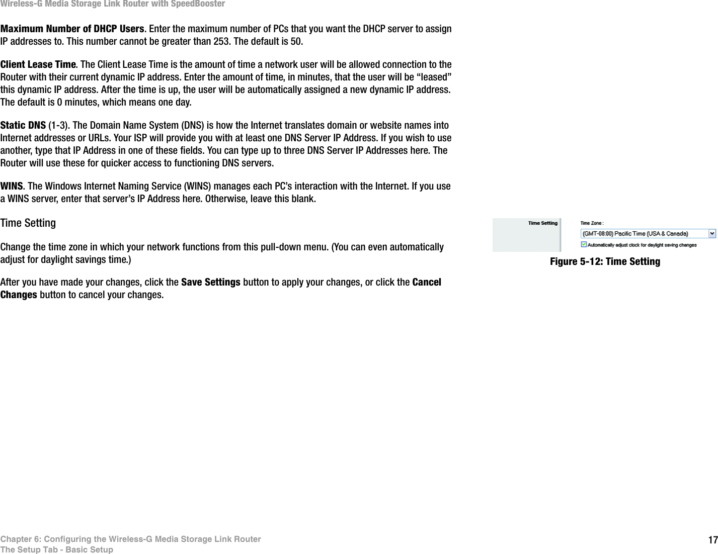
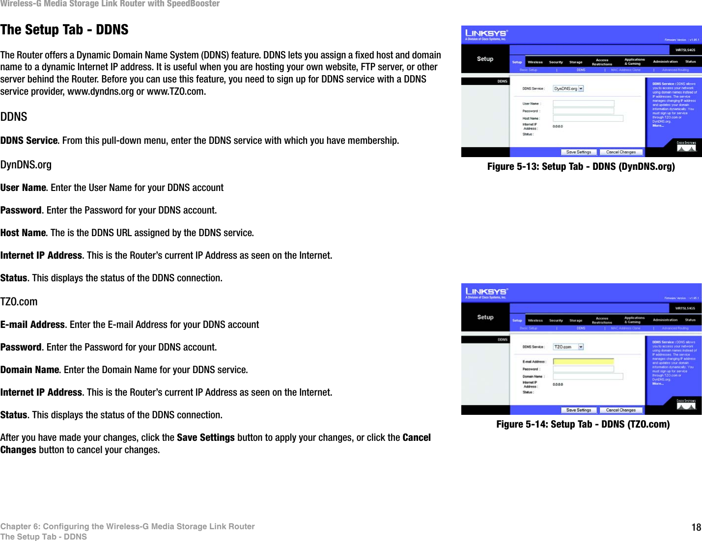
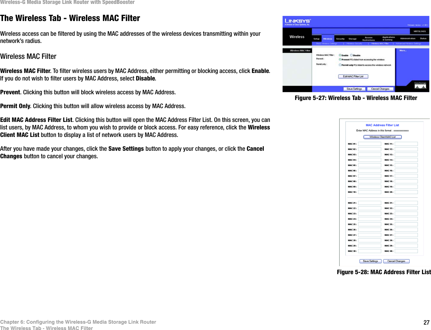
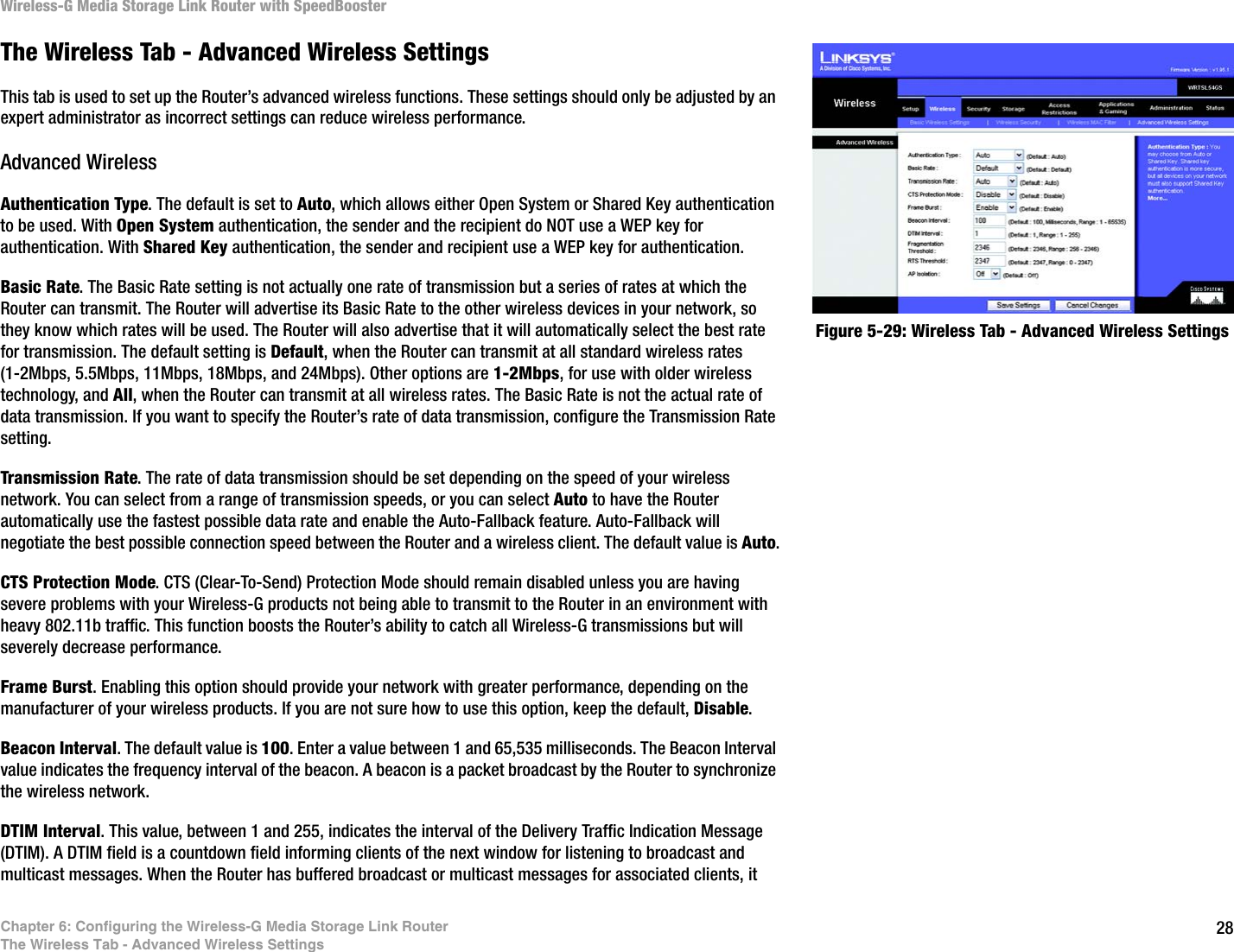
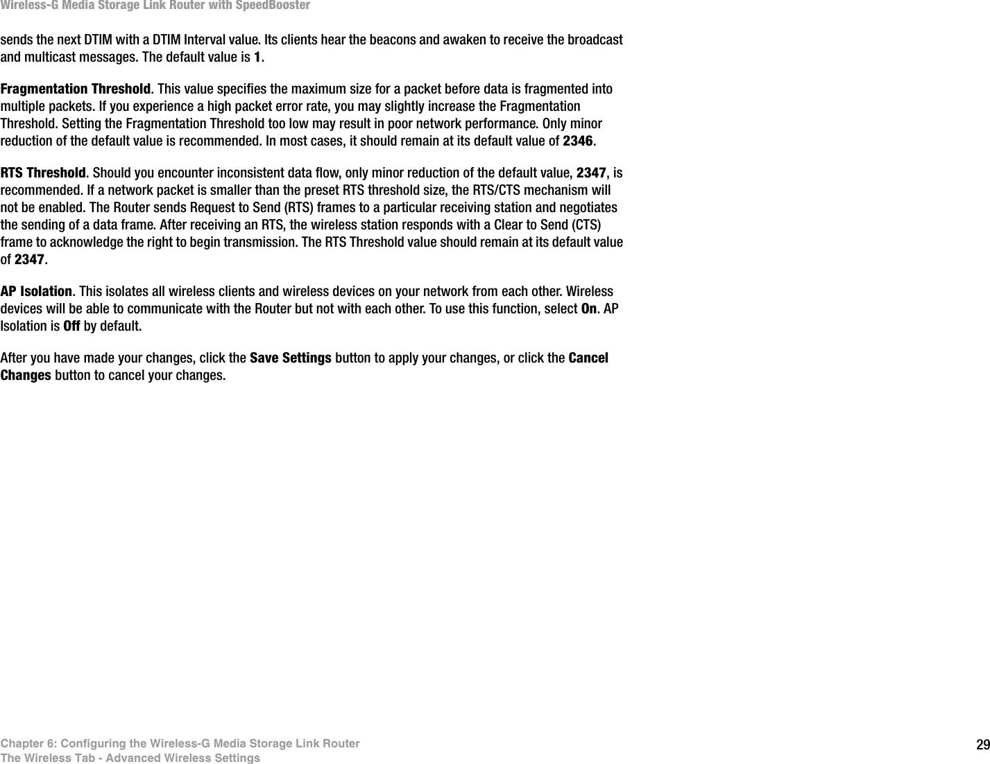
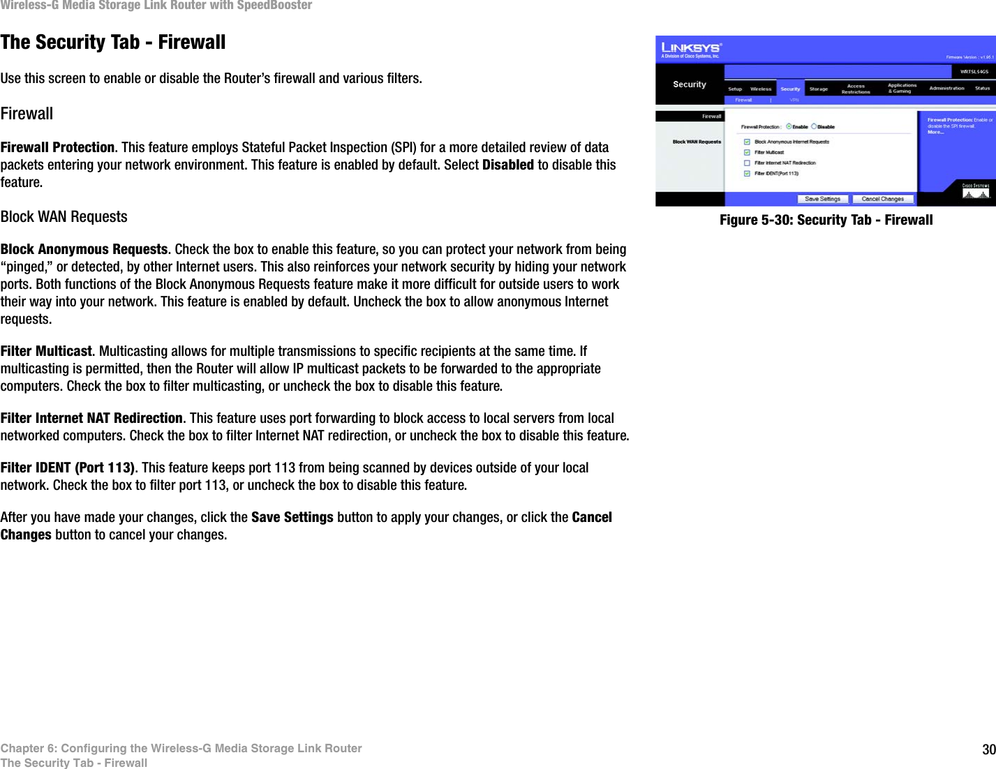
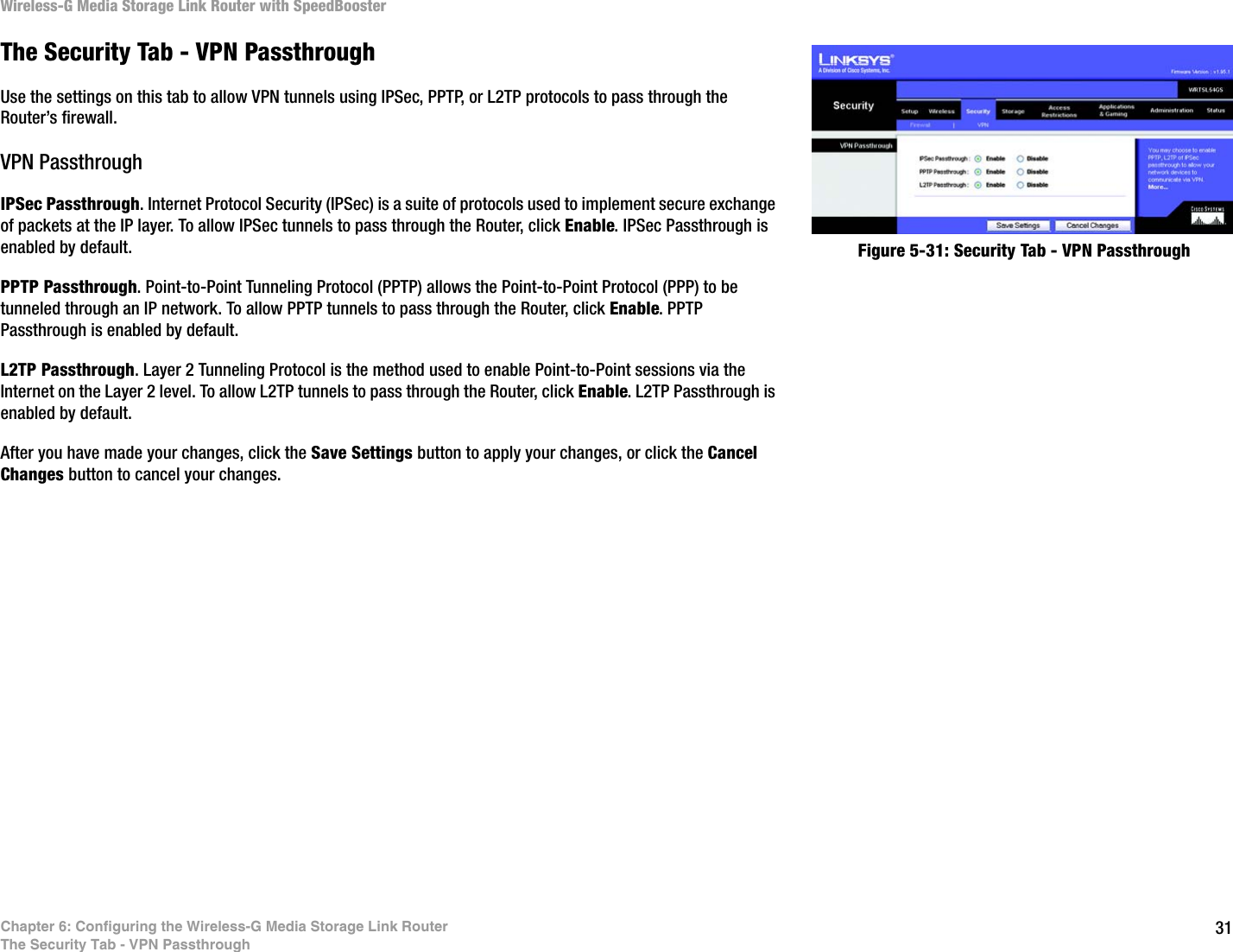
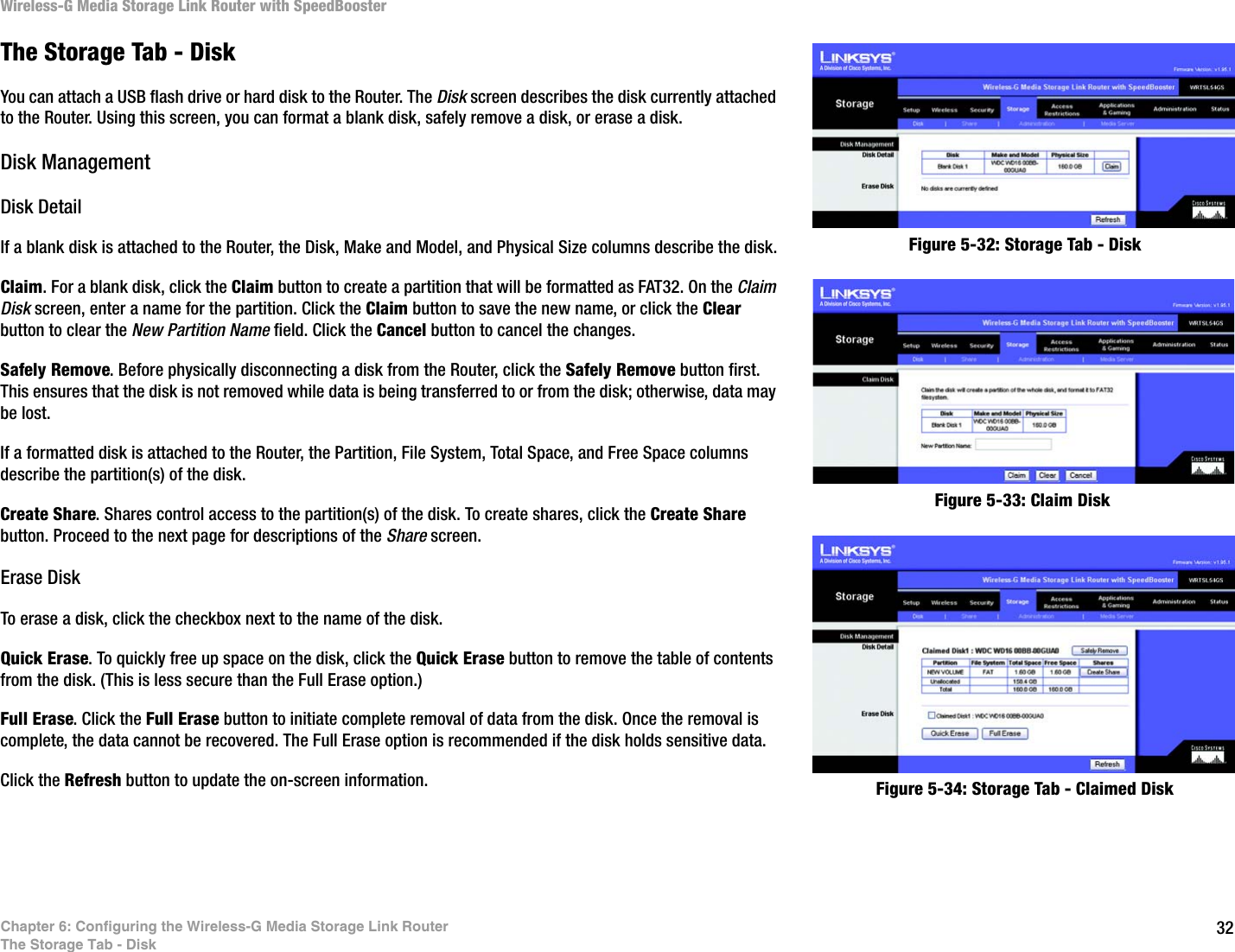
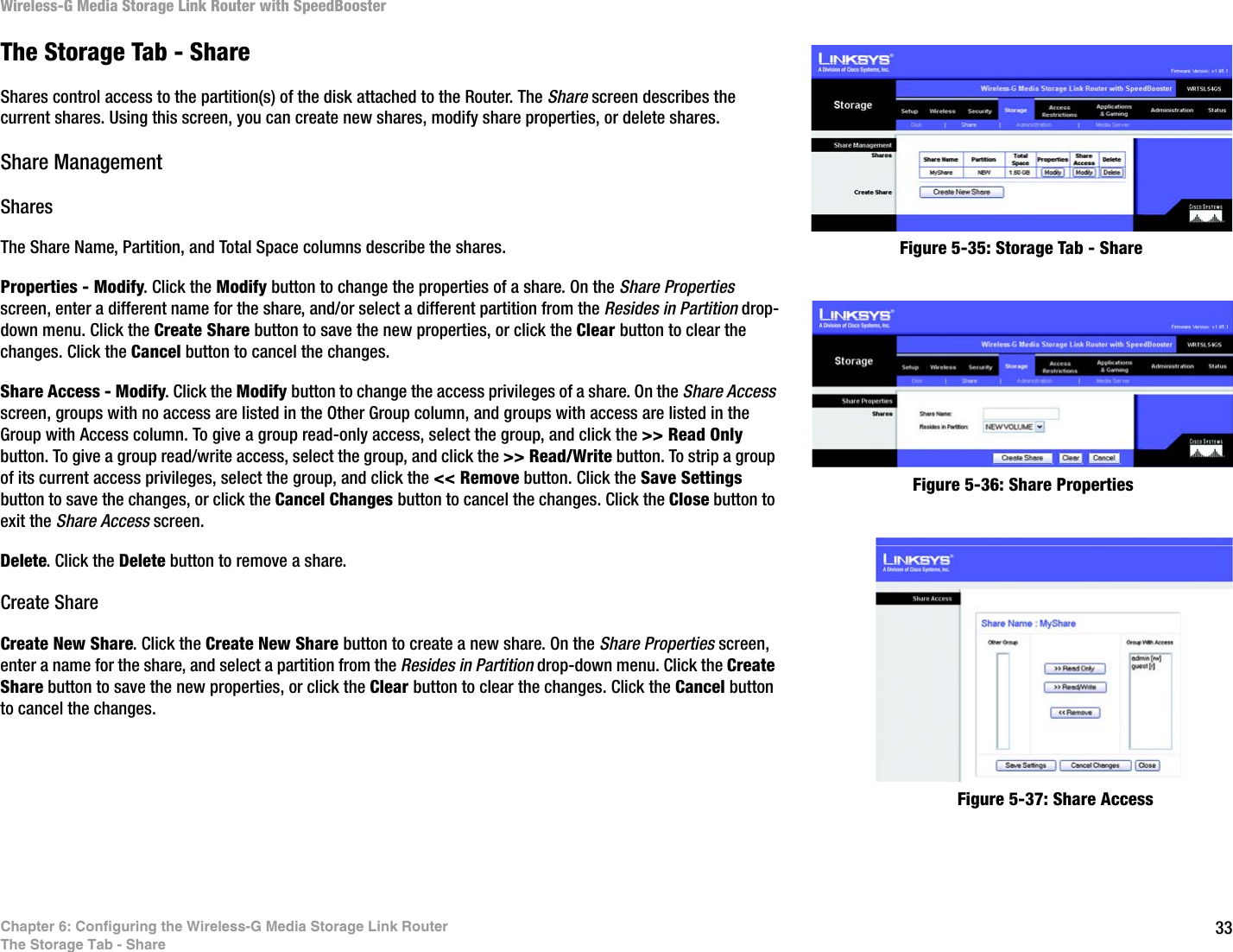
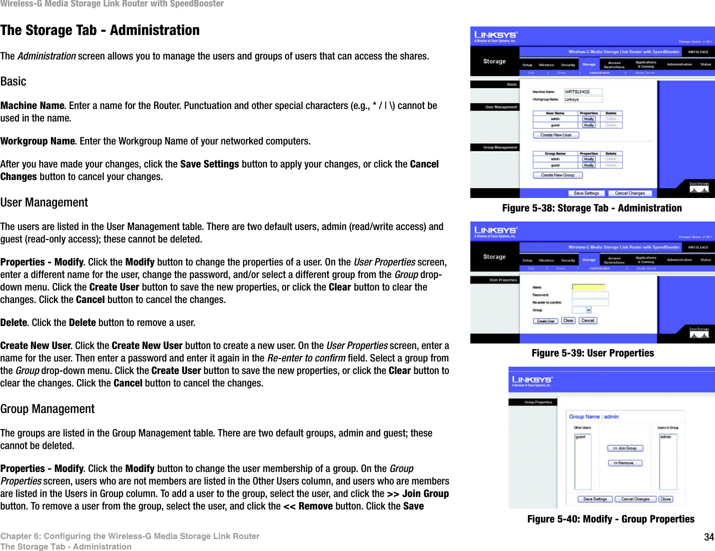
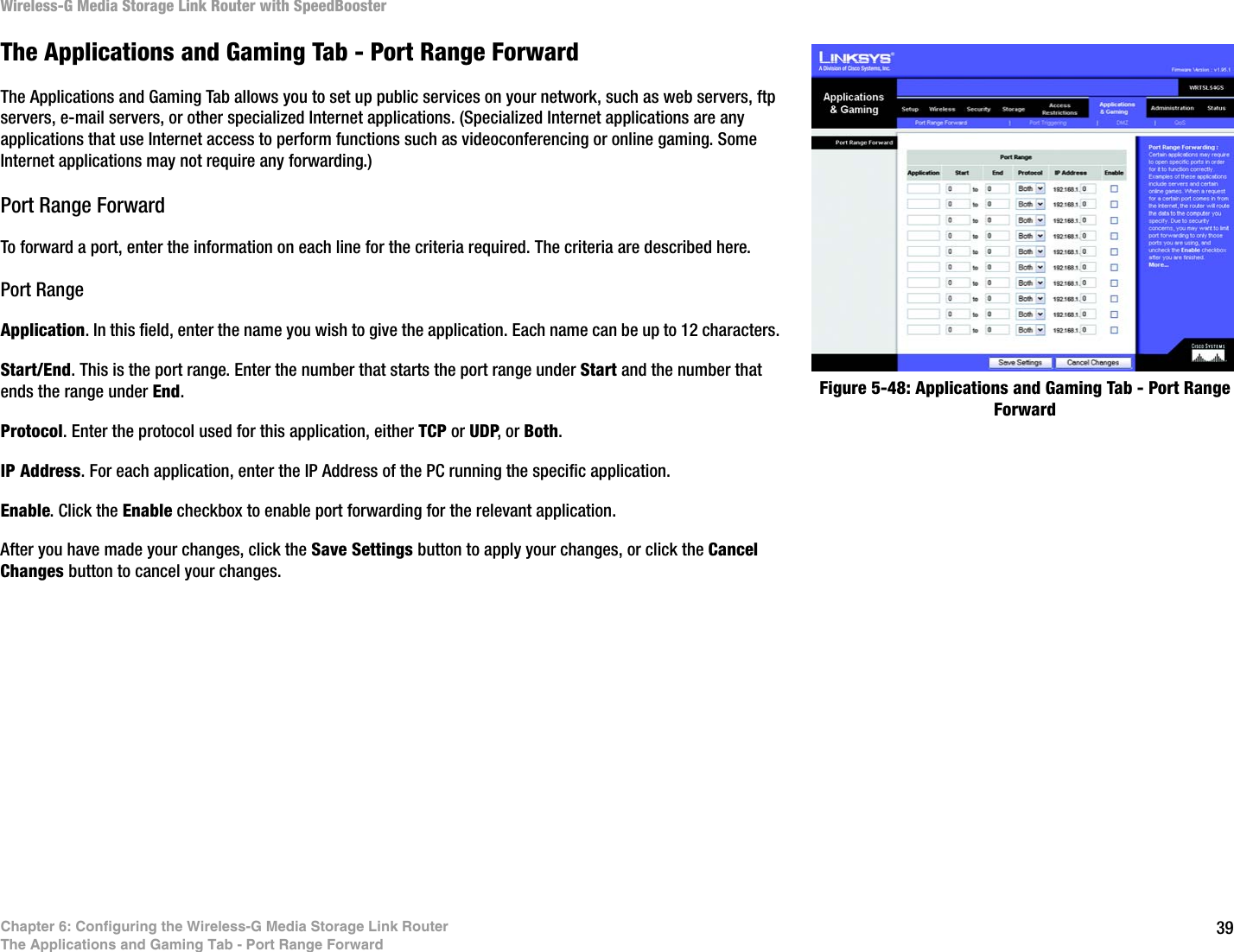
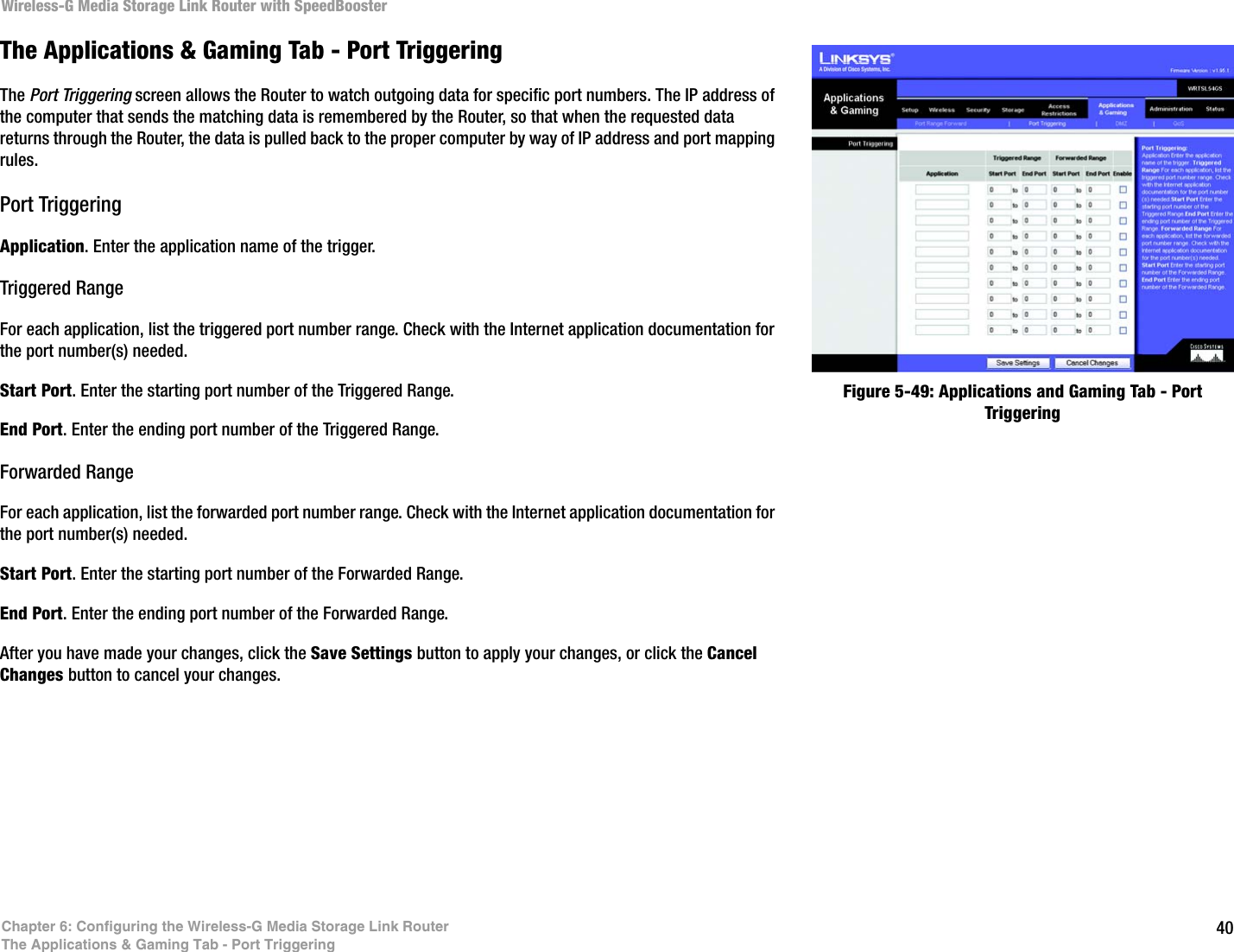
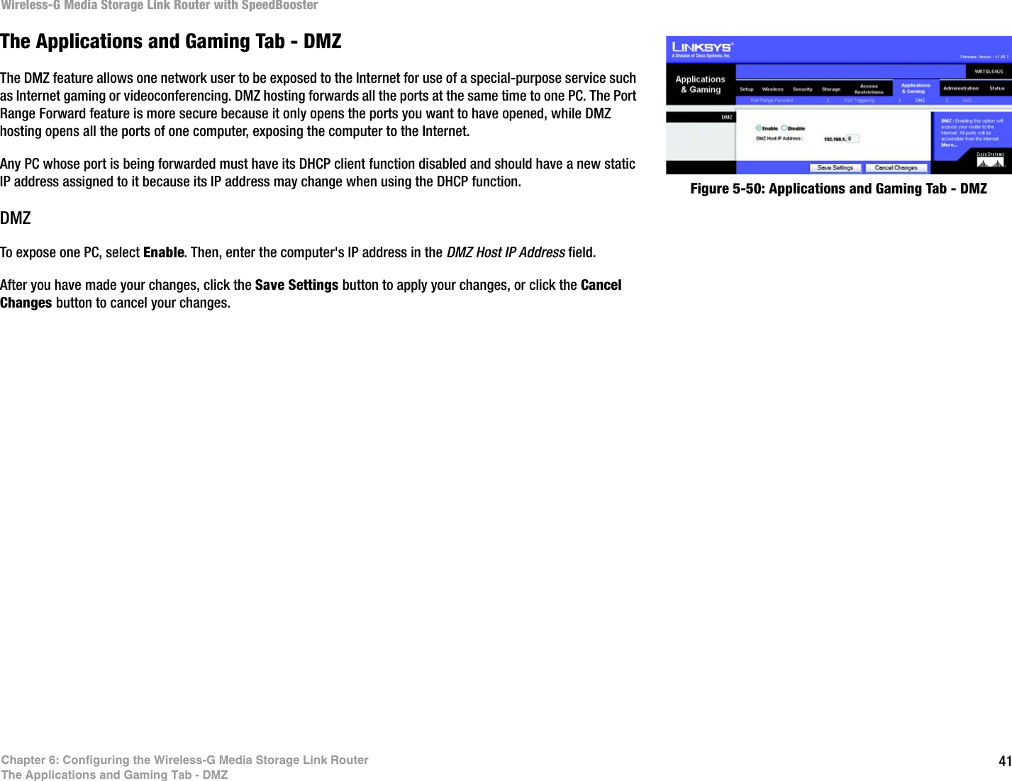
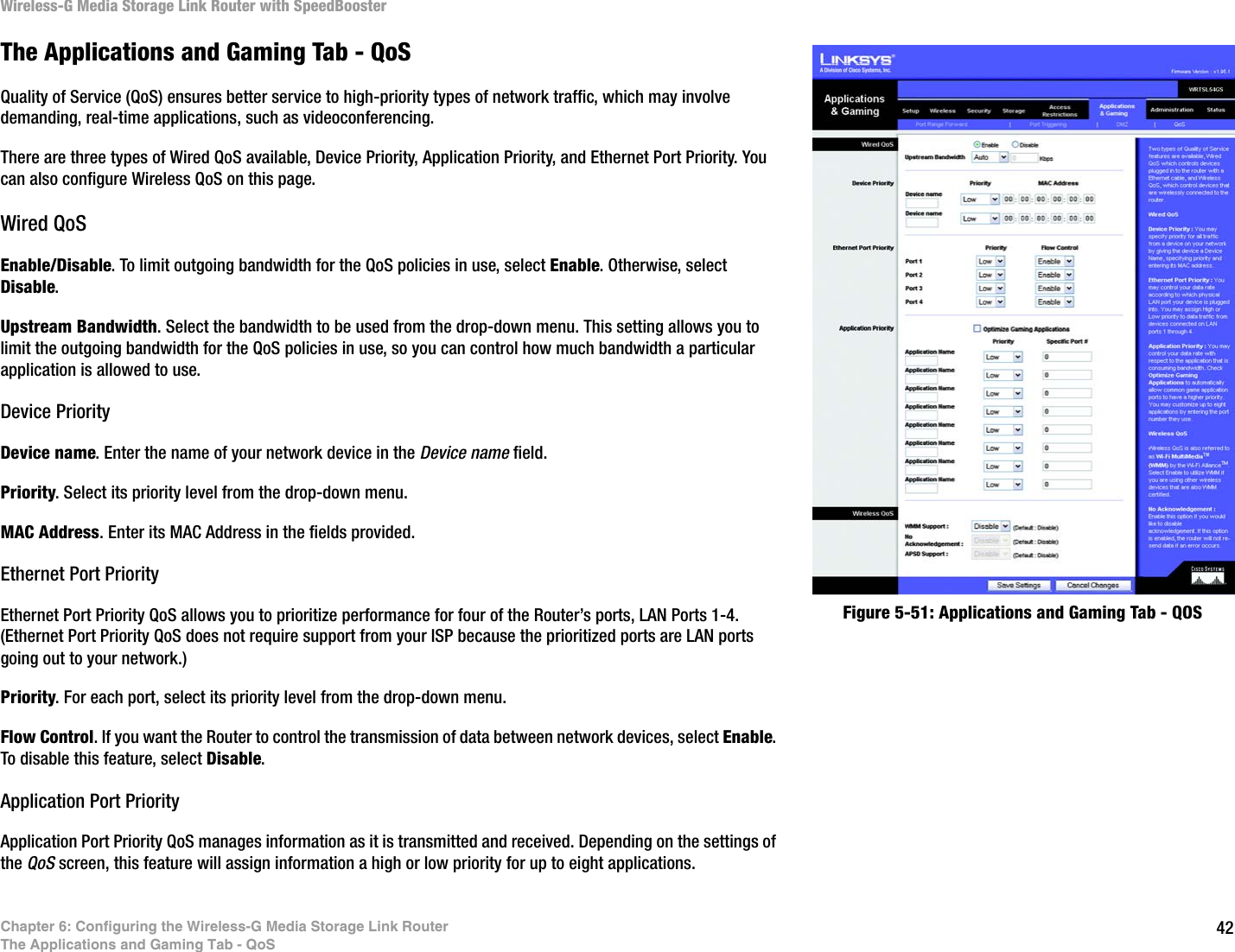
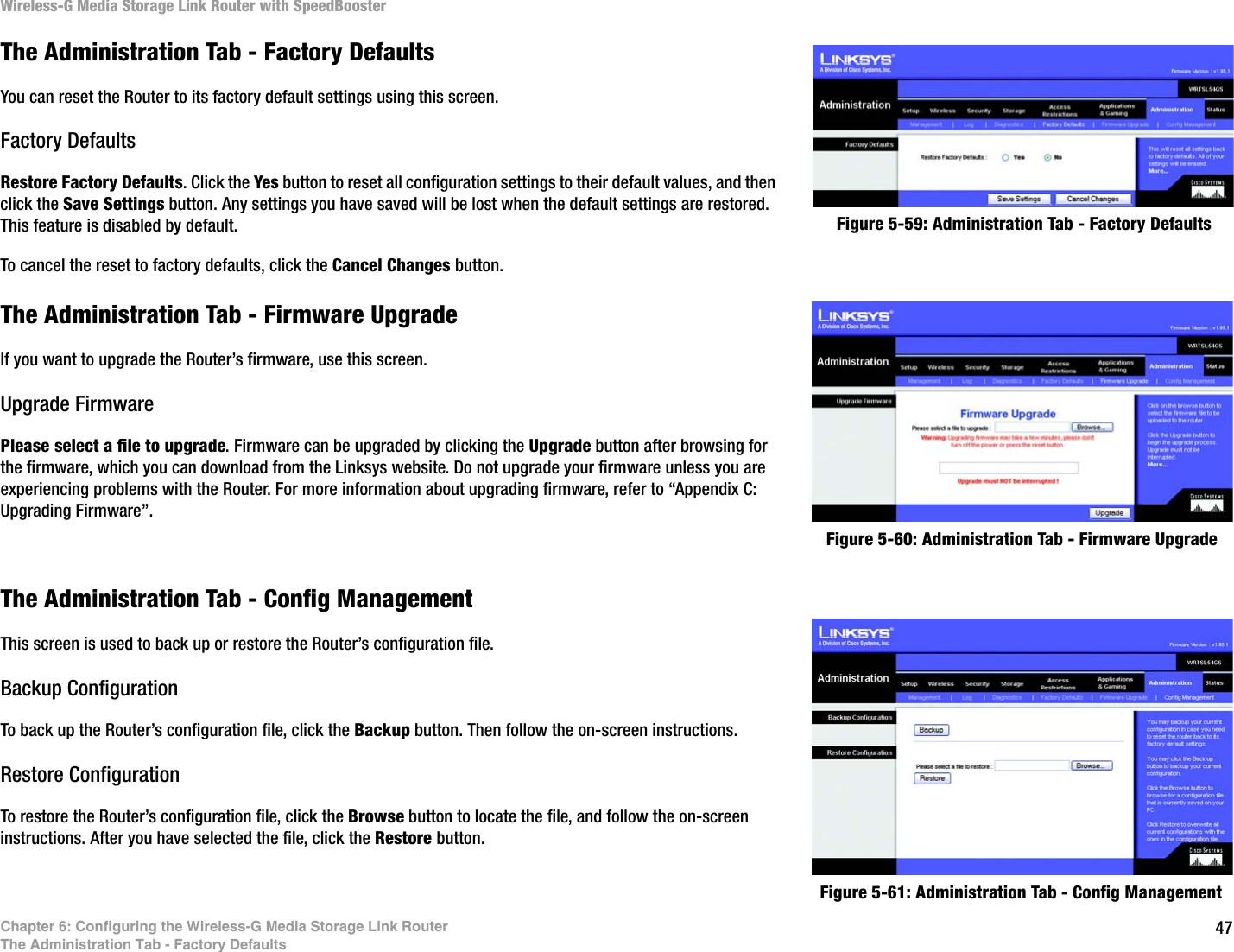
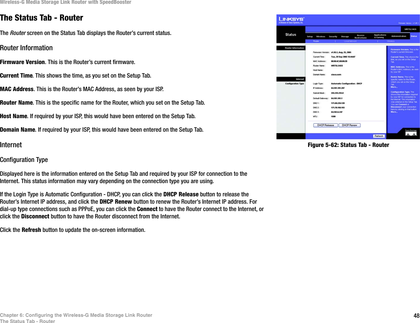
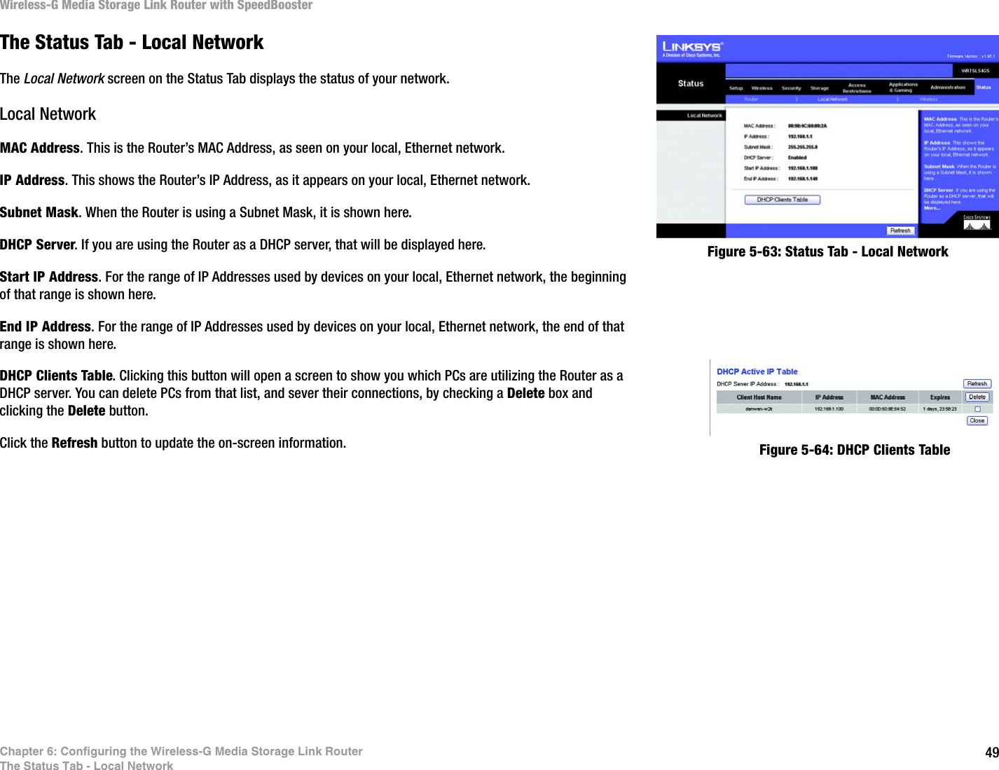
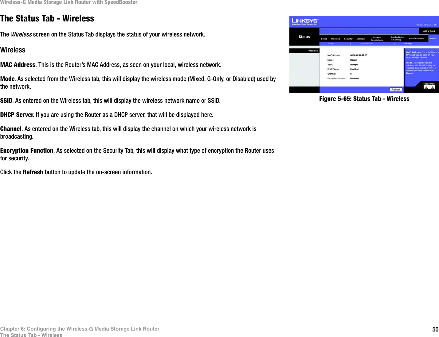
LINKSYS WTSLGS Wireless-G Media Storage Link Router with SB User Manual Book
LINKSYS LLC Wireless-G Media Storage Link Router with SB Book
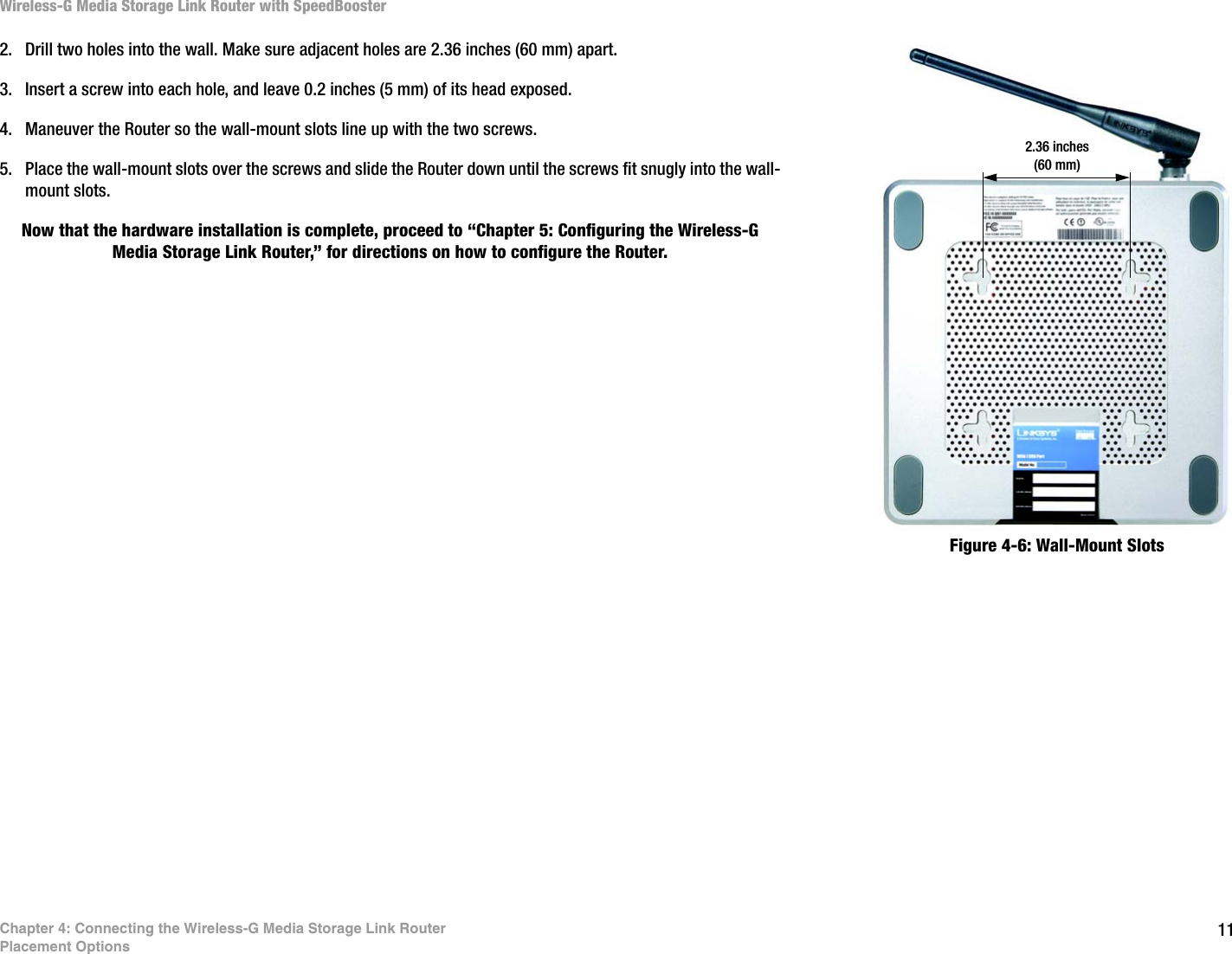
UserManual.wiki
>
LINKSYS
>
WTSLGS User Manual
>
Users Manual 1
Contents
1.
Users Manual 1
2.
Users Manual 2
Users Manual 1
Navigation menu
Upload a User Manual
Namespaces
Wiki Guide
HTML
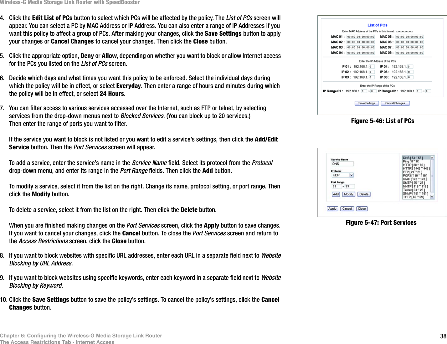
PDF
Info
Views
User Manual
Discussion / Help
Navigation