LINKSYS WUSB54GP Wireless-G USB 2.0 Pen-type Network Adapter User Manual
LINKSYS LLC Wireless-G USB 2.0 Pen-type Network Adapter Users Manual
LINKSYS >
Users Manual
COPYRIGHT & TRADEMARKS
Specifications are subject to change without notice. Linksys is a registered trademark or
trademark of Cisco Systems, Inc. and/or its affiliates in the U.S. and certain other countries.
Copyright © 2003 Cisco Systems, Inc. All rights reserved. Other brands and product
names are trademarks or registered trademarks of their respective holders.
LIMITED WARRANTY
Linksys guarantees that every Wireless-G USB Network Adapter will be free from physical
defects in material and workmanship for three years from the date of purchase, when
used within the limits set forth in the Specifications section of this User Guide. If the product
proves defective during this warranty period, call Linksys Technical Support in order
to obtain a Return Authorization number. BE SURE TO HAVE YOUR PROOF OF PURCHASE
ON HAND WHEN CALLING. When returning a product, mark the Return
Authorization number clearly on the outside of the package and include a copy of your
original proof of purchase. RETURN REQUESTS CANNOT BE PROCESSED WITHOUT
PROOF OF PURCHASE. All customers located outside of the United States of America
and Canada shall be held responsible for shipping and handling charges.
IN NO EVENT SHALL LINKSYS'S LIABILITY EXCEED THE PRICE PAID FOR THE
PRODUCT
FROM DIRECT, INDIRECT, SPECIAL, INCIDENTAL, OR CONSEQUENTIAL DAMAGES
RESULTING FROM THE USE OF THE PRODUCT, ITS ACCOMPANYING SOFTWARE,
OR ITS DOCUMENTATION. LINKSYS OFFERS NO REFUNDS FOR ITS PRODUCTS.
Linksys makes no warranty or representation, expressed, implied, or statutory,
with respect to its products or the contents or use of this documentation and all accompanying
software, and specifically disclaims its quality, performance, merchantability, or
fitness for any particular purpose. Linksys reserves the right to revise or update its products,
software, or documentation without obligation to notify any individual or entity.
Please direct all inquiries to:
Linksys P.O. Box 18558, Irvine, CA 92623.
SAFETY AND REGULATORY NOTICES
FCC STATEMENT
The Wireless-G USB Network Adapter has been tested and found to comply with the
specifications for a Class B digital device, pursuant to Part 15 of the FCC Rules.
Operation is subject to the following two conditions:
(1) This device may not cause harmful interference, and
(2) This device must accept any interference received, including interference that may
cause undesired operation.
These limits are designed to provide reasonable protection against harmful interference
in a residential installation. This equipment generates, uses, and can radiate radio frequency
energy and, if not installed and used according to the instructions, may cause
harmful interference to radio communications. However, there is no guarantee that
interference
will not occur in a particular installation. If this equipment does cause harmful
interference to radio or television reception, which is found by turning the equipment off
and on, the user is encouraged to try to correct the interference by one or more of the
following measures:
• Reorient or relocate the receiving antenna
• Increase the separation between the equipment or devices
• Connect the equipment to an outlet other than the receiver's
• Consult a dealer or an experienced radio/TV technician for assistance
FCC Caution: Any change or modification to the product not expressly approved by
Linksys could void the user's authority to operate the device.
FCC RF Radiation Exposure Statement
To comply with the FCC and ANSI C95.1 RF exposure limits, the antenna(s) for this
device must comply with the following:
• This device complies with FCC RF Exposure limits set forth for an uncontrolled
environment, under 47 CFR 2.1093 paragraph (d)(2) and must
not be co-located or operating in conjunction with any other antenna or transmitter.
End-users must be provided with specific operations for satisfying RF exposure compliance.
Note: Dual antennas used for diversity operation are not considered co-located.
Canadian Department of Communications Industry Canada (IC) Notice
This Class B digital apparatus complies with Canadian ICES-003 and RSS-210.
Cet appareil numérique de la classe B est conforme à la norme NMB-003 et CNR-210
du Canada.
"To prevent radio interference to the licensed service, this device is intended to be operated
indoors and away from windows to provide maximum shielding. Equipment (or its
transmit antenna) that is installed outdoors is subject to licensing."
" Pour empêcher que cet appareil cause du brouillage au service faisant l'objet d'une
licence, il doit être utilisé à l'intérieur et devrait être placé loin des fenêtres afin de fournir
un écran de blindage maximal. Si le matériel (ou son antenne d'émission) est installé à
l'extérieur, il doit faire l'objet d'une licence. "
EC DECLARATION OF CONFORMITY (EUROPE)
Linksys Group declares that the Instant Wireless® Series products included in the Instant
Wireless® Series conform to the specifications listed below, following the provisions of the
European R&TTE directive 1999/5/EC, EMC directive 89/336/EEC, and Low Voltage
directive 73/23/EEC:
For 2.4 GHz devices with 100 mW radios, the following standards were applied:
• ETS 300-826, 301 489-1 General EMC requirements for Radio equipment.
• EN 609 50 Safety
• ETS 300-328-2 Technical requirements for Radio equipment.
Caution: This equipment is intended to be used in all EU and EFTA countries. Outdoor
use may be restricted to certain frequencies and/or may require a license for operation.
Contact local Authority for procedure to follow.
Cisco-Linksys, LLC declares that WUSB54GP ( FCC ID: Q87-WUSB54GP ) is
limited in CH1~CH11 by specified firmware controlled in USA.
Note: Combinations of power levels and antennas resulting in a radiated power level of
above 100 mW equivalent isotropic radiated power (EIRP) are considered as not compliant
with the above mentioned directive and are not allowed for use within the European
community and countries that have adopted the European R&TTE directive 1999/5/EC
and/or the CEPT recommendation Rec 70.03.
For more details on legal combinations of power levels and antennas, contact Linksys
Corporate Compliance.
• Linksys Group vakuuttaa täten että Wireless-G USB Network Adapter tyyppinen laite
on direktiivin 1999/5/EY, direktiivin 89/336/EEC ja direktiivin 73/23/EEC oleellisten
vaatimusten ja sitä koskevien näiden direktiivien muiden ehtojen mukainen.
• Linksys Group déclare que la Wireless-G USB Network Adapter est conforme aux
conditions essentielles et aux dispositions relatives à la directive 1999/5/EC, la directive
89/336/EEC, et à la directive 73/23/EEC.
• Belgique B L'utilisation en extérieur est autorisé sur le canal 11 (2462 MHz), 12 (2467
MHz), et 13 (2472 MHz). Dans le cas d'une utilisation privée, à l'extérieur d'un bâtiment,
au-dessus d'un espace public, aucun enregistrement n'est nécessaire pour
une distance de moins de 300m. Pour une distance supérieure à 300m un enregistrement
auprès de l'IBPT est requise. Pour une utilisation publique à l'extérieur de
bâtiments, une licence de l'IBPT est requise. Pour les enregistrements et licences,
veuillez contacter l'IBPT.
• France F:
2.4 GHz Bande : les canaux 10, 11, 12, 13 (2457, 2462, 2467, et 2472 MHz respectivement)
sont complétement libres d'utilisation en France (en utilisation intérieur).
Pour ce qui est des autres canaux, ils peuvent être soumis à autorisation selon le
départment. L'utilisation en extérieur est soumis à autorisation préalable et très
restreint.
2.4 GHz Band: only channels 10, 11, 12, 13 (2457, 2462, 2467, and 2472 MHz
respectively) may be used freely in France for indoor use. License required for outdoor
installations.
• Deutschland D: Anmeldung im Outdoor-Bereich notwending, aber nicht
genehmigungspflichtig.
Bitte mit Händler die Vorgehensweise abstimmen.
• Germany D: License required for outdoor installations. Check with reseller for procedure
to follow.
• Italia I: E' necessaria la concessione ministeriale anche per l'uso interno. Verificare
con i rivenditori la procedura da seguire. L'uso per installazione in esterni non e' permessa.
• Italy I: License required for indoor use. Use with outdoor installations not allowed.
• The Netherlands NL License required for outdoor installations. Check with reseller for
procedure to follow.
• Nederlands NL Licentie verplicht voor gebruik met buitenantennes. Neem contact op
met verkoper voor juiste procedure.
WUSB54G-UG-3015A KL
Table of Contents
Chapter 1
:
Introduction 1
The Wireless-G USB P en Type Network Adapter1t 1
Features 1
Chapter 2
:
Planning Your Wireless Network 2
Network Topology 2
Ad-Hoc versus Infrastructure Mode 2
Chapter 3: Getting to Know the
Wireless-G USB Network Adapter 4
The Adapter’s Ports 4
The Adapter’s LEDs 4
Chapter 4: Software Installation
and Configuration for Windows 2000 5
Chapter 5: Hardware Installation 9
Connecting the Adapter 9
Chapter 6: Driver Installation for Windows XP 11
Windows XP Wireless Zero Configuration 12
Chapter 7: Using the WLAN Monitor 14
Overview 14
Accessing the WLAN Monitor 14
Link Information 15
Site Survey 17
Profiles 18
Creating a New Profile 20
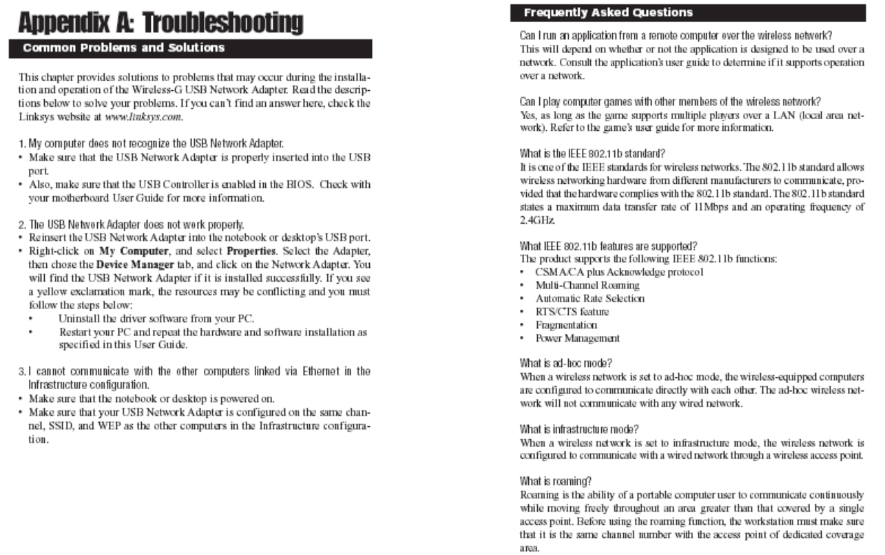
Appendix A: Troubleshooting 26
Common Problems and Solutions 26
Frequently Asked Questions 27
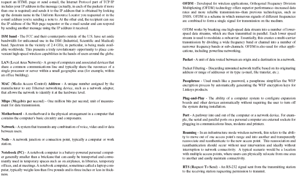
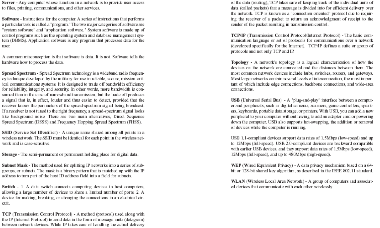
Appendix B: Glossary 30
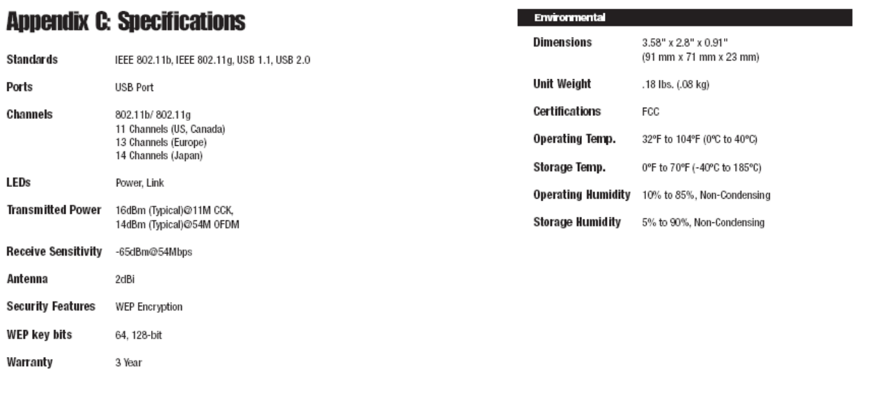
Appendix C: Specifications 38
Environmental 39
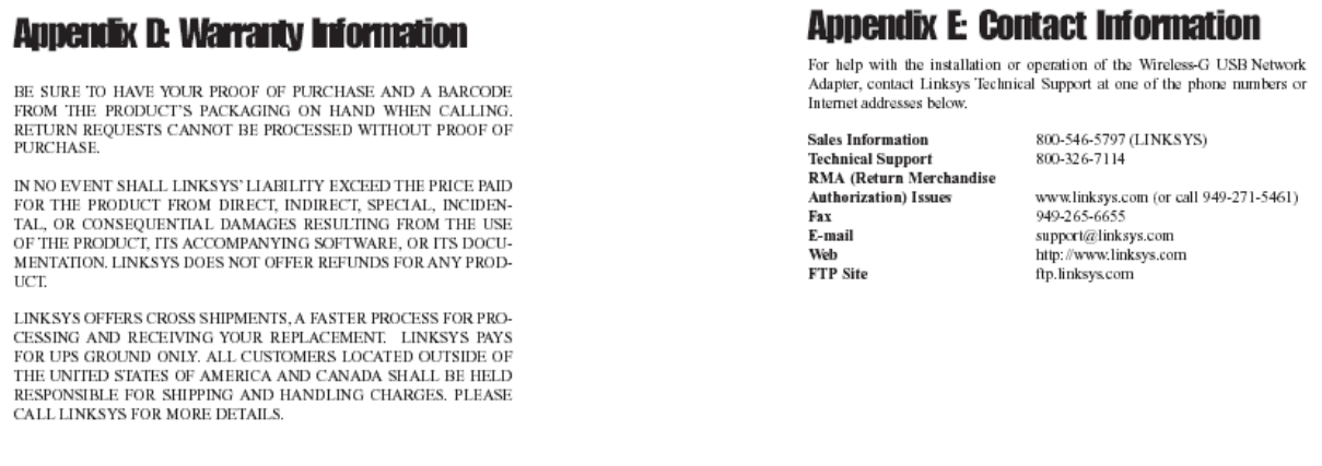
Appendix D: Warranty Information 40
Appendix E: Contact Information 41
Chapter 1: Introduction
Connect your USB-equipped desktop or notebook computer to a wireless network
at incredible speeds with the Linksys Wireless-G USB Network Adapter.
By incorporating two new, blazing fast technologies -- USB 2.0 and Wireless-
G -- the Adapter delivers data rates up to 54Mbps (5 times as fast as 802.11b),
without the trouble of opening up the case of your desktop computer.
To install, simply plug the Adapter into any available USB port. (It's compatible
with both USB 1.1 and 2.0 ports, but 2.0 will yield the fastest speeds.) It
gets its power through the USB connection, so no power cord is necessary. The
included Setup Wizard walks you through configuring the Adapter to your
wireless network settings, step by step. The Wireless-G USB Network Adapter
is also compatible with the Wireless-B (802.11b) network standard, with data
rates up to 11Mbps. And your wireless communications can be protected by
128-bit encryption, so your data stays secure.
The Wireless-G USB Network Adapter's high-gain antenna lets you put your
computer almost anywhere in the building, without the cost and hassle of running
cables. Now you don't have to drill holes in your walls and climb through
the attic or cellar to get connected to the network. Once you're connected, you
can keep in touch with your e-mail, access the Internet, use instant messaging
to chat with friends, and share files and other resources such as printers and
hard disk storage space with other computers on the network.
So don't hassle with running cables through your house -- get connected the
easy way with the Wireless-G USB Network Adapter.
• Compatible with 802.11g and 802.11b (2.4GHz) Stardards
• Support USB 2.0 with up to 54Mbps, High-Speed Data Transfer Rate with
Automatic Fallback
• Plug-and-Play Operation Provides Easy Setup
• Supports up to 128-bit WEP Encryption Security
• Compatible with Microsoft Windows 2000 and XP
The Wireless-G USB Pen Type Network Adapter
Features
Chapter 2: Planning Your Wireless
Network
A wireless local area network (WLAN) is exactly like a regular local area network
(LAN), except that each computer in the WLAN uses a wireless device to
connect to the network. Computers in a WLAN share the same frequency
channel and SSID, which is an identification name for wireless devices.
Unlike wired networks, wireless networks have two different modes in which
they may be set up: infrastructure and ad-hoc. An infrastructure configuration
is a WLAN and wired LAN communicating to each other through an
access point. An ad-hoc configuration is wireless-equipped computers
communicating
directly with each other. Choosing between these two modes
depends on whether or not the wireless network needs to share data or peripherals
with a wired network or not.
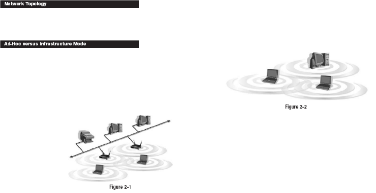
If the computers on the
wireless network need to
be accessed by a wired
network or need to share a
peripheral, such as a
printer,
with the wired network
computers, the wireless
network should be set up
in infrastructure mode.
(See Figure 2-1.) The
basis of infrastructure
mode centers around an
access point, which serves
as the main point of communications in a wireless network. Access points
transmit data to PCs equipped with wireless network cards, which can roam
within a certain radial range of the access point. Multiple access points can be
arranged to work in succession to extend the roaming range, and can be set up
to communicate with your Ethernet (wired) hardware as well.
Network Topology
Ad-Hoc versus Infrastructure Mode
If the wireless network is relatively small and needs to share resources only
with the other computers on the wireless network, then the ad-hoc mode can
be used. (See Figure 2-2.) Ad-hoc mode allows computers equipped with wireless
transmitters and receivers to communicate directly with each other, eliminating
the need for an access point. The drawback of this mode is that, in Ad-
Hoc mode, wireless-equipped computers are not able to communicate with
computers on a wired network. And, of course, communication between the
wireless-equipped computers is limited by the distance and interference directly
between them.
Chapter 3: Getting to Know the
Wireless-G USB Pen Type Network
Adapter
The Network Adapter is connected to your PC through its USB port. All power
is provided through the USB connection, making a power adapter unnecessary.
The Network Adapter’s LEDs show you how the Adapter is functioning.
Power Green. This LED will light up to let you know that the Adapter is
adequately powered over the USB connection.
Link Green. The Link LED will be lit steadily when the Network
Adapter is connected to your wireless network. The LED will
blink when there is wireless network traffic.
The USB Port
The Adapter’s LEDs
Chapter 4: Software Installation and
Configuration for Windows 2000
The Wireless-G USB Network Adapter Setup Wizard will guide you through
the installation procedure. The Setup Wizard will install the WLAN Monitor
and driver, as well as configure the Adapter.
1. Insert the Setup Wizard CD-ROM into your CD-ROM drive. The Setup
Wizard should run automatically, and Figure 4-1 should appear. If it does
not, click the Start button and choose Run. In the field that appears, enter
D:\setup.exe (if “D” is the letter of your CD-ROM drive).
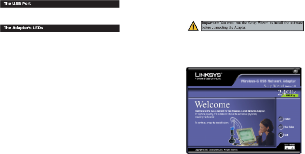
To install the Adapter, click the Install button on theWelcome screen. Click
User Guide to view this User Guide or click Exit to exit the Setup Wizard.
Figure 4-1
Important: You must run the Setup Wizard to install the software
before connecting the Adapter.
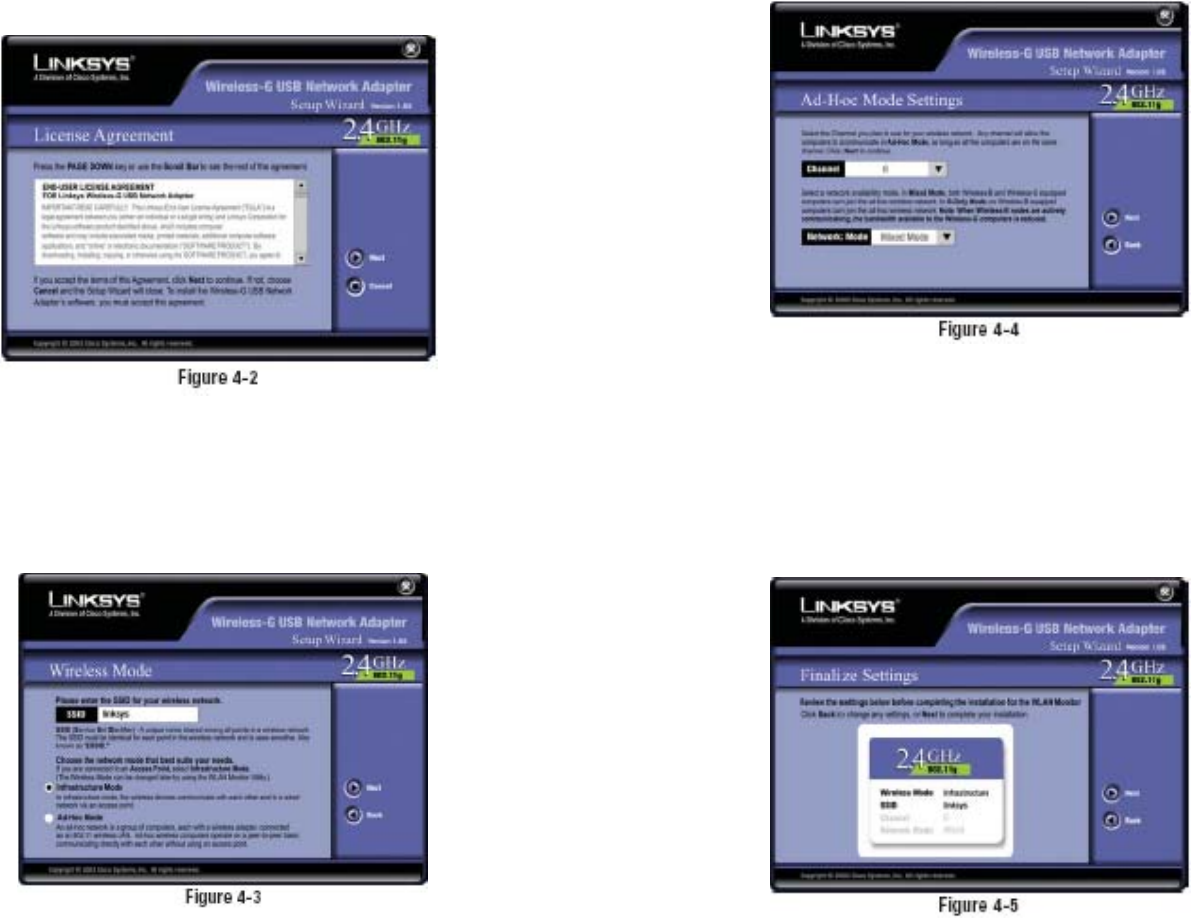
2. Read the License Agreement and click the Next button to continue the
installation. If
you click the
Cancel button,
you will end the
installation.
3. The following screen, shown in Figure 4-3, will ask for some information
about your wireless network. In the SSID field, enter your network’s SSID
(Service Set Identifier). The SSID is your network name and must be identical
for all devices in the network. The default setting is linksys (all lowercase).
Next, choose a wireless mode. Click the Infrastructure Mode radio button
if you want your wireless computers to network with computers on your
wired network using a wireless access point. Click the Ad-Hoc Mode radio
button if you
want multiple
wireless computers
to network
directly
with each other.
Click the Next
button to continue,
or click the
Back button to
return to the
previous page.
4. If you chose
I n f r a s t r u c t u r e
Mode, go to Step
5 now. If you
chose Ad-Hoc
Mode, select the
correct operating
channel for your
network from the
Channel dropdown
menu.
Then, select the
Network Mode
from the dropdown
menu.
Click the Next
button, and go to Step 5. Click the Back button to change any settings.
Channel - The channel you choose should match the channel set on the
other devices in your wireless network. If you are unsure about which channel
to use, select the default channel (Channel 6).
Network Mode - Keep the default setting, Mixed, if you have Wireless-G
and Wireless-B devices in your network. Select G-Only if you have only
Wireless-G devices in your network.
5. The Setup Wizard
will ask you to
review your settings
before it
starts to copy
files. Click the
Next button to
save these settings,
or click the
Back button to
change any settings.
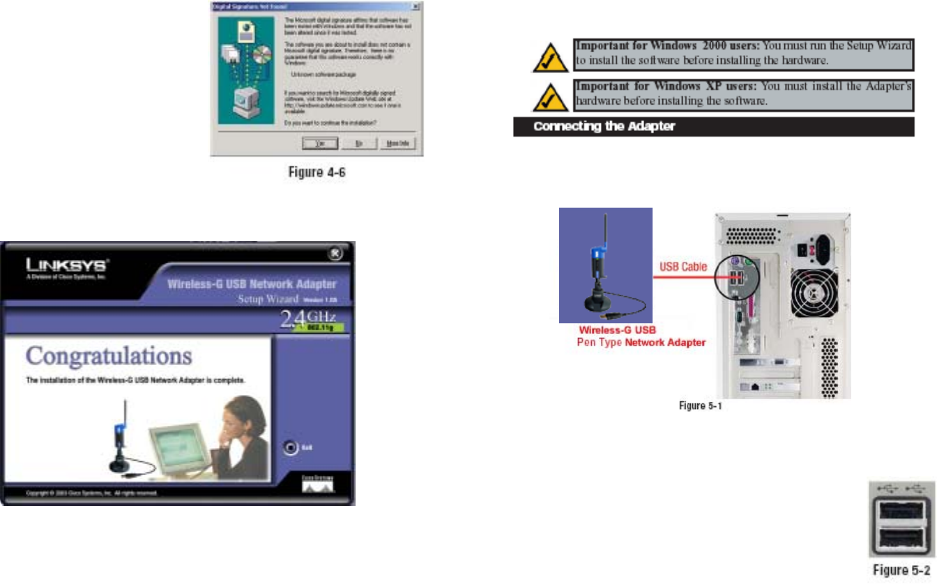
6. At this point, you may see a warning
screen, such as that shown in
Figure 4-6 , asking if you’d like to
cease installation. You can click
the Yes button to continue; the
Adapter will function properly.
7. After the files have been successfully copied, the screen in Figure 4-7 will
appear. Click the Exit button.
Proceed to “Chapter 5: Hardware Installation.”
Chapter 5: Hardware Installation
1. The Adapter comes with the USB cable you will use to connect the Adapter
to your PC. (See Figure 5-1.)
2. Connect one end of the USB cable to the USB port of the Adapter.
3. Connect the other end of the USB cable to one of the USB
ports on your computer (see Figure 5-2).
Adapter
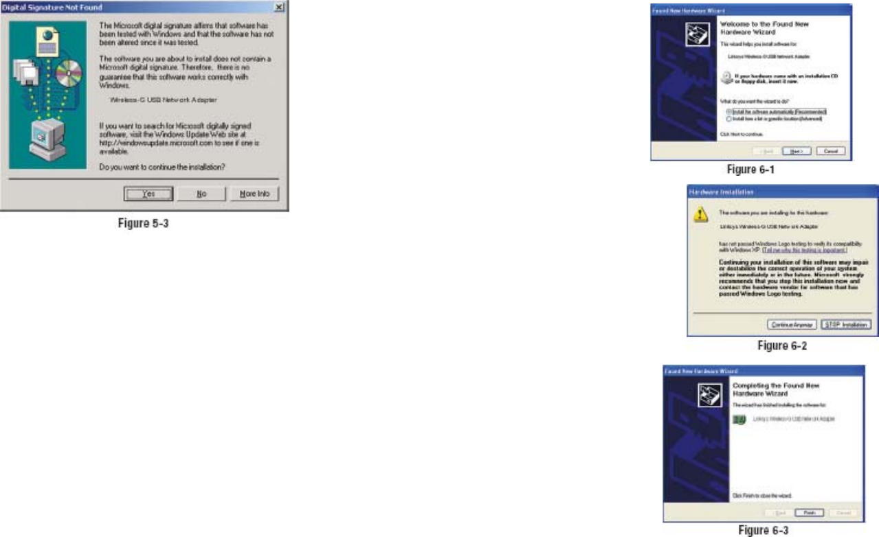
4. When Windows 2000 begins installing the Network Adapter’s driver file, a
screen similar to that shown in Figure 5-3 will appear, stating that a digital
signature was not found. This software has been tested and found to work
properly with Windows 2000. Click the Yes button to continue installation.
If your PC is running Windows XP, proceed to “Chapter 6: Driver
Installation for Windows XP.”
If your PC is running Windows 2000, the installation of the Wireless-B
USB Network Adapter is complete. If you want to check the link information,
search for available wireless networks, or make additional configuration
changes, proceed to “Chapter 7: Using the WLAN Monitor.”
Chapter 6: Driver Installation for
Windows XP
After connecting the Adapter to
your PC, as shown in Chapter 5,
you’ll need to install the driver.
1. Windows XP will
automatically
detect the Adapter.
Insert the Setup CD-ROM
into the CD-ROM drive.
Click the radio button next to
Install the software
automatically
(Recommended)
(as shown in Figure 6-1).
Then click the Next button.
2. A screen similar to that shown in
Figure 6-2 will appear, asking if
you wish to discontinue installation.
This software has been tested
and found to work properly
with Windows XP. Click the
Continue Anyway button to
continue installation.
3. The next screen shows that the
Wizard is complete. Click the
Finish button. The drivers are
now installed.
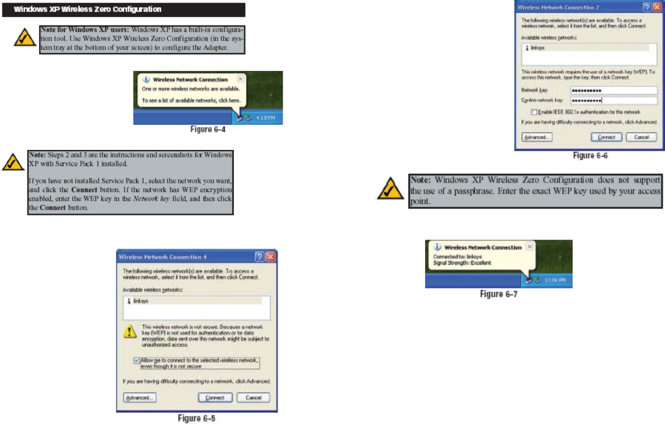
1. After installing the Adapter,
the Windows XP Wireless
Zero Configuration icon
will appear in your computer’s
system tray (see Figure
6-4). Double-click the icon.
2. The screen that appears will show any available wireless network. Select
the network you want.
If this network has WEP
encryption enabled, go to
step 3.
If this network does not
have WEP encryption
enabled, then Figure 6-5
will appear. Make sure the
box next to Allow me to
connect to the selected
wireless network, even
though it is not secure is
checked. Then click the
Connect button, and go to
step 4.
3. If WEP is enabled, the
screen in Figure 6-6 will
appear. Enter the WEP key
of your wireless network in
the Network key field, and
re-enter it in the Confirm
network key field. Then click
the Connect button, and go
to step 4.
4. The screen in Figure 6-7 will appear if your connection is active.
For more information about wireless networking on a Windows XP computer,
click Start and then Help and Support. Enter the keyword wireless in the
field provided, and press the Enter key.
Congratulations! The installation of the Wireless-G USB Network
Adapter is complete.
Chapter 7: Using the WLAN Monitor
Use the WLAN Monitor to check the link information, search for available
wireless networks, or create profiles that hold different configuration settings.
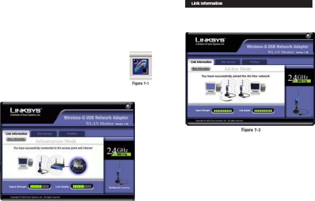
After installing the Adapter, the Wireless-G USB Network Adapter WLAN
Monitor icon will appear in your system tray. Double-click the icon (see Figure
7-1).
The Link Information screen will appear. (See Figure 7-2.) From
this screen, you can find out how strong the current wireless
signal is and how good the connection’s quality is. You can also
click the More Information button to view additional status
information about the current wireless connection. To search for
available wireless networks, click the Site Survey tab. To
perform configuration changes, click the Profiles tab.
Accessing the WLAN Monitor
Overview
The Link Information screen, shown again in Figure 7-3, displays the signal
strength and link quality information about the current connection and provides
a button to click for additional status information.
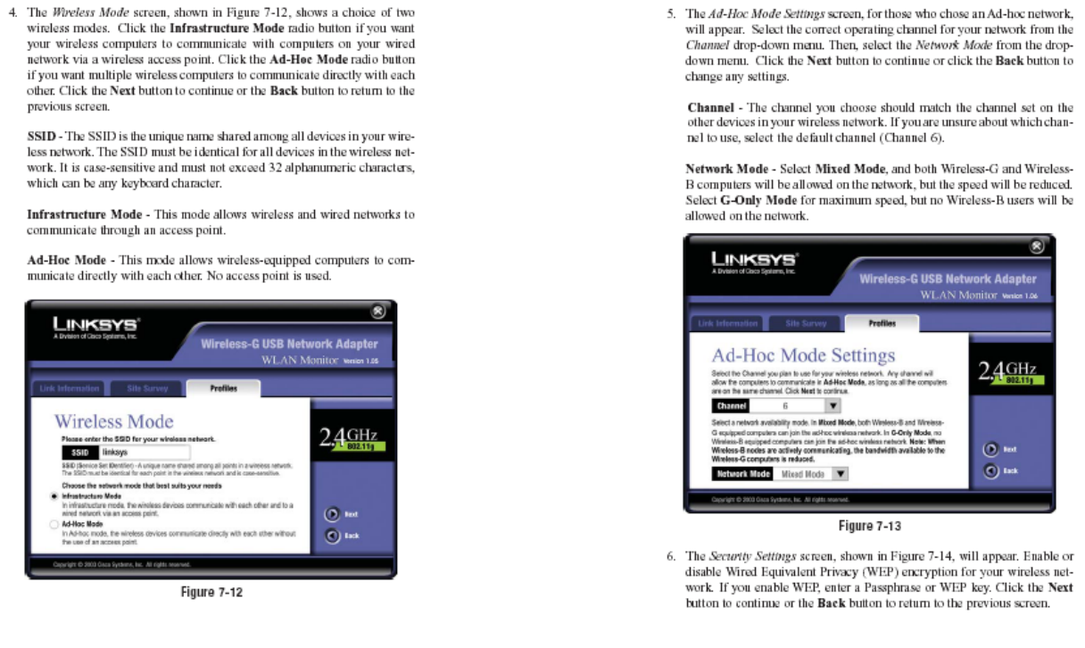
Ad-Hoc Mode or Infrastructure Mode - The screen indicates whether the
Adapter is currently working in ad-hoc or infrastructure mode.
Signal Strength - The Signal Strength bar indicates the signal strength.
Link Quality - The Link Quality bar indicates the quality of the wireless network
connection.
Click the More Information button to view more information about the wireless
network connection, shown on the following page and in Figure 7-4..
Click the X (Close) button in the upper right corner to exit the WLAN Monitor.
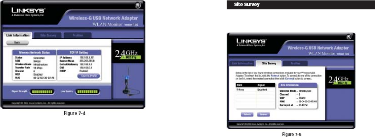
Wireless Network Status
Status - The status of the wireless network connection.
SSID - The unique name of the wireless network.
Wireless Mode - The mode of the wireless network currently in use.
Transfer Rate - The data transfer rate of the current connection.
Channel - The channel to which the wireless network devices are set.
WEP - The status of the WEP encryption security feature.
MAC - The MAC address of the wireless network’s access point.
TCP/IP Setting
IP Address - The IP Address of the Adapter.
Subnet Mask - The Subnet Mask of the Adapter.
Default Gateway - The Default Gateway address of the Adapter.
DNS - The DNS address of the Adapter.
DHCP - The status of the DHCP client.
Signal Strength - The Signal Strength bar indicates the signal strength.
Link Quality - The Link Quality bar indicates the quality of the wireless network
connection.
Click the Back button to return to the initial Link Information screen. Click the
X (Close) button in the upper right corner to exit the WLAN Monitor.
The Site Survey screen, shown in Figure 7-5, displays a list of infrastructure and
ad-hoc networks available for connection.
SSID - The SSID or unique name of the wireless network.
Signal - The percentage of signal strength, from 0 to 100%.
Site Information
Wireless Mode - The mode of the wireless network currently in use.
Channel - The channel to which the wireless network devices are set.
WEP - The status of the WEP encryption security feature.
MAC - The MAC address of the wireless network’s access point.
Surveyed at - The time at which the wireless network was scanned.
Refresh - Click the Refresh button to perform a new search for wireless
devices.
Connect - To connect to one of the networks on the list, select the wireless
network,
and click the Connect button. If the wireless network has WEP encryption
enabled, you will see the screen shown in Figure 7-6.
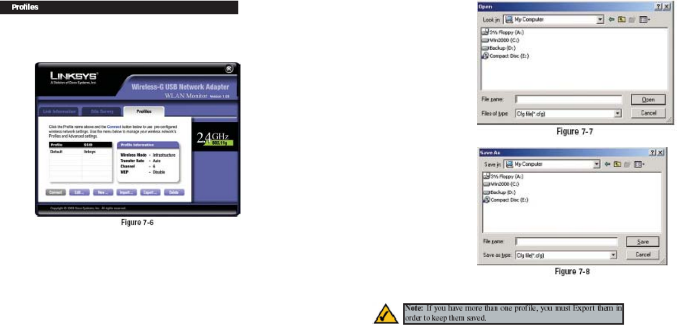
The Profiles screen, shown in Figure 7-6, lets you save different configuration
profiles for different network setups. You can also import or export profiles.
The default profile holds the initial configuration saved when you ran the Setup
Wizard.
Profile - Name of the connection profile.
SSID - The wireless network’s unique name, as set in the connection profile.
Profile Information
Wireless Mode - The mode of the wireless network currently in use.
Transfer Rate - The data transfer rate of the current connection. (In Auto
mode, the Adapter dynamically shifts to the fastest data transfer rate possible
at any given time.)
Channel - The channel to which the wireless network devices are set.
WEP - The status of the WEP encryption security feature.
Connect - To connect to a wireless network using a specific profile, select the
profile, and click the Connect button.
Edit - Select a profile, and click the Edit button to change an existing profile.
New - Click the New button to create a new profile. See the next section,
“Creating a New Profile,” for detailed instructions.
Import - Click the
Import button to
import a profile
that has been saved
in another location.
Select the appropriate
file, as shown in
Figure 7-7, and
click the Open button.
Export - To save
the profile(s) in a
different location,
click the Export
button. Direct
Windows to the
appropriate folder,
as shown in Figure
7-8, and click the
OK button.
Delete - Click the Delete button to delete a profile.
Click the X (Close) button in the upper right corner to exit the WLAN Monitor.
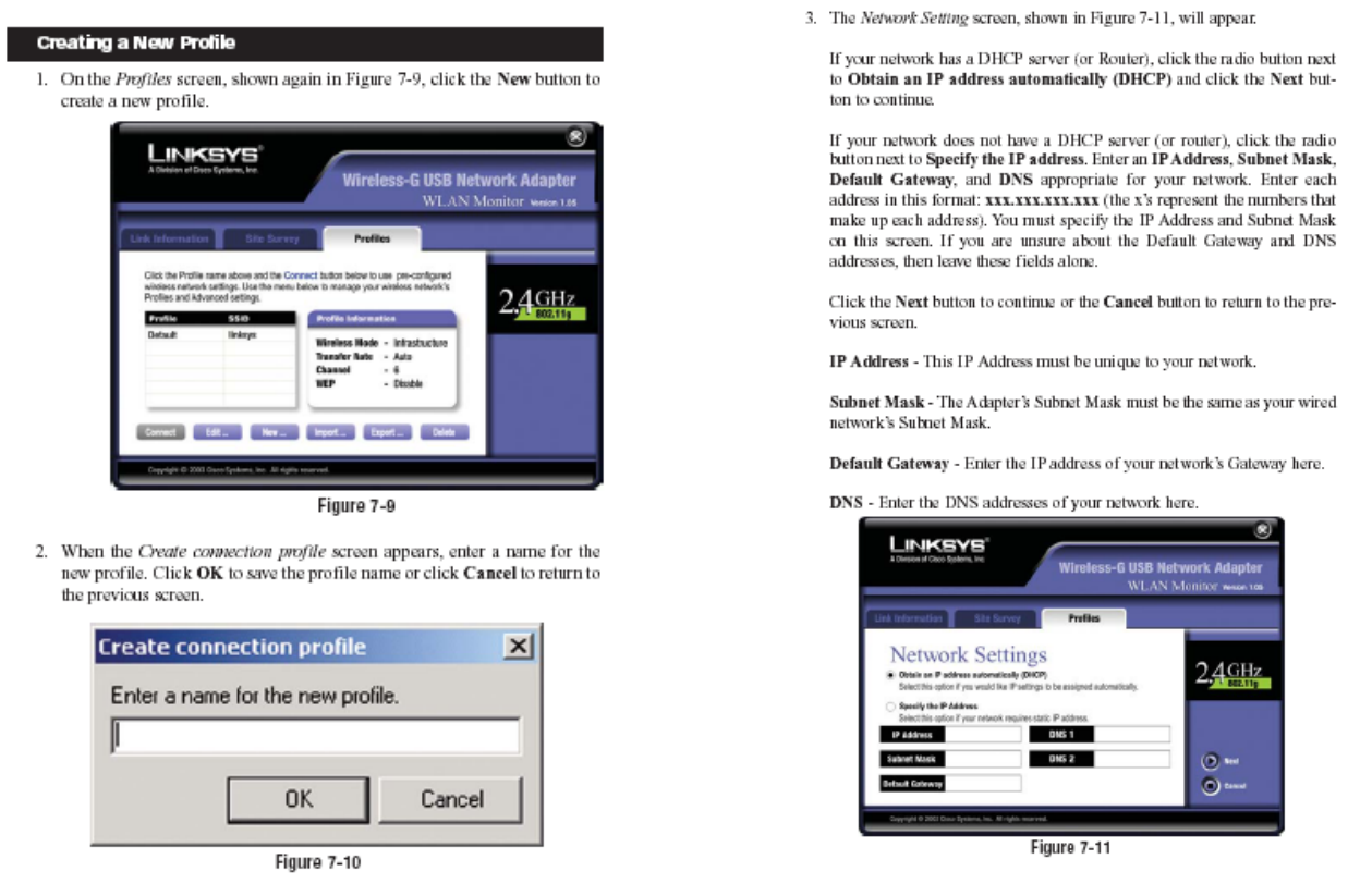
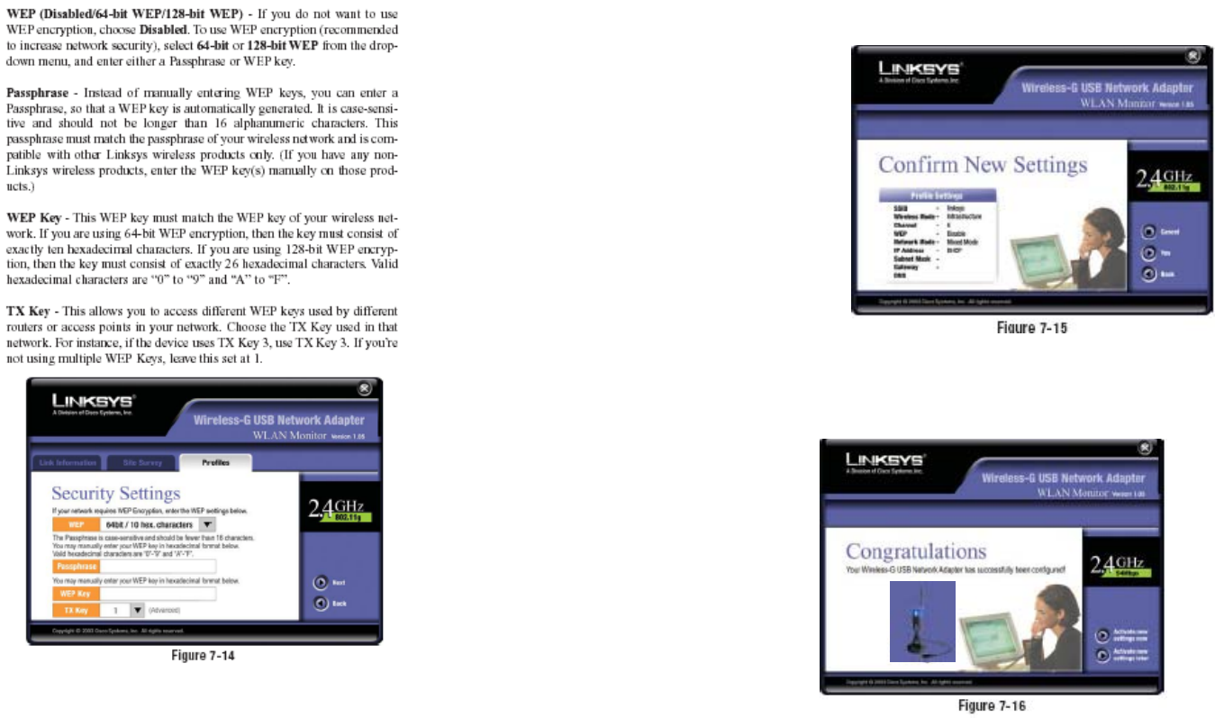
7. The Confirm New Settings screen will appear (shown in Figure 7-15). To
save the new settings, click the Yes button. To cancel the settings and return
to the
P r o f i l e s
screen, click
the Cancel
button. To
edit the new
s e t t i n g s ,
click the
Back button.
8. The Congratulations screen (Figure 7-16) will appear next. Click Activate
new settings now to implement the new settings immediately and return to
the Link Information screen. Click Activate new settings later to keep the
current settings active, and return to the Profiles screen so that you can edit
your profile
or create
another profile.
You have successfully created a connection profile. Click the X (Close) button
in the upper right corner to exit the WLAN Monitor.