LINKSYS WVC200 Wireless-G PTZ Internet Camera with Audio User Manual
LINKSYS LLC Wireless-G PTZ Internet Camera with Audio
UserManual.wiki
>
LINKSYS
>
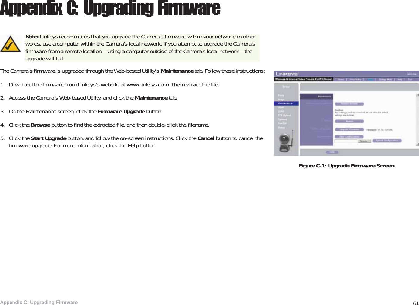
WVC200 User Manual
Manual
Navigation menu
Upload a User Manual
Namespaces
Wiki Guide
HTML
PDF
Info
Views
User Manual
Discussion / Help
Navigation