User manual
A Division of Cisco Systems, Inc.
®
Model No.
PTZ Internet Camera
Wireless-G
WVC210
User Guide
WIRELESS
GHz
2.4
802.11g
with Audio

Wireless-G PTZ Internet Camera with Audio
Copyright and Trademarks
Specifications are subject to change without notice. Linksys is a registered trademark or trademark of Cisco
Systems, Inc. and/or its affiliates in the U.S. and certain other countries. Copyright © 2005 Cisco Systems, Inc. All
rights reserved. Other brands and product names are trademarks or registered trademarks of their respective
holders.
How to Use this Guide
This User Guide has been designed to make understanding networking with the Camera easier than ever. Look for
the following items when reading this guide:
In addition to these symbols, there are definitions for technical terms that are presented like this:
Also, each figure (diagram, screenshot, or other image) is provided with a figure number and description, like
this:
Figure numbers and descriptions can also be found in the “List of Figures” section in the “Table of Contents”.
This exclamation point means there is a Caution or warning and is
something that could damage your property or the Camera.
word: definition.
This checkmark means there is a Note of interest and is something
you should pay special attention to while using the Camera.
This question mark provides you with a reminder about something
you might need to do while using the Camera.
Figure 0-1: Sample Figure Description
WVC210-UG-60113 CB

Wireless-G PTZ Internet Camera with Audio
Table of Contents
Chapter 1: Planning Your Wireless Network. . . . . . . . . . . . . . . . . . . . . . . . . . . . . . . . . 4
Introduction. . . . . . . . . . . . . . . . . . . . . . . . . . . . . . . . . . . . . . . . . . . . . . . . . . . . . . . . . . . 4
Ad-Hoc and Infrastructure Modes. . . . . . . . . . . . . . . . . . . . . . . . . . . . . . . . . . . . . . . . . . 4
Network Layout. . . . . . . . . . . . . . . . . . . . . . . . . . . . . . . . . . . . . . . . . . . . . . . . . . . . . . . . 5
Chapter 2: Getting to Know the PTZ Internet Camera. . . . . . . . . . . . . . . . . . . . . . . . . 6
Camera LCD Screen and Built-in Microphone. . . . . . . . . . . . . . . . . . . . . . . . . . . . . . . . . 6
Camera LEDs. . . . . . . . . . . . . . . . . . . . . . . . . . . . . . . . . . . . . . . . . . . . . . . . . . . . . . . . . . 6
Camera Ports and Button . . . . . . . . . . . . . . . . . . . . . . . . . . . . . . . . . . . . . . . . . . . . . . . . 7
Chapter 3: Connecting the PTZ Internet Camera . . . . . . . . . . . . . . . . . . . . . . . . . . . . . 8
Overview . . . . . . . . . . . . . . . . . . . . . . . . . . . . . . . . . . . . . . . . . . . . . . . . . . . . . . . . . . . . . 8
Connection to a Wired Network for Setup. . . . . . . . . . . . . . . . . . . . . . . . . . . . . . . . . . . . 8
Connection to a Wireless Ad-Hoc Network for Setup . . . . . . . . . . . . . . . . . . . . . . . . . . . 9
Moving the Camera to a Different Network. . . . . . . . . . . . . . . . . . . . . . . . . . . . . . . . . . . 9
Chapter 4: Setting up and Mounting the Wireless-G Internet Camera . . . . . . . . . 11
Setup Wizard. . . . . . . . . . . . . . . . . . . . . . . . . . . . . . . . . . . . . . . . . . . . . . . . . . . . . . . . . 11
Placement Options . . . . . . . . . . . . . . . . . . . . . . . . . . . . . . . . . . . . . . . . . . . . . . . . . . . . 18
Audio Option . . . . . . . . . . . . . . . . . . . . . . . . . . . . . . . . . . . . . . . . . . . . . . . . . . . . . . . . . 18
Chapter 5: Installing and Using the Internet Camera Viewer & Recorder Utility. 19
Overview . . . . . . . . . . . . . . . . . . . . . . . . . . . . . . . . . . . . . . . . . . . . . . . . . . . . . . . . . . . . 19
Installing the Viewer & Recorder Utility. . . . . . . . . . . . . . . . . . . . . . . . . . . . . . . . . . . . . 19
Using the Viewer & Recorder Utility . . . . . . . . . . . . . . . . . . . . . . . . . . . . . . . . . . . . . . . 21
Setting Up the Camera . . . . . . . . . . . . . . . . . . . . . . . . . . . . . . . . . . . . . . . . . . . . . . . . . 25
Using File Finder . . . . . . . . . . . . . . . . . . . . . . . . . . . . . . . . . . . . . . . . . . . . . . . . . . . . . . 29
Chapter 6: Setting up the Linksys SoloLinktm DDNS Service. . . . . . . . . . . . . . . . . 30
Overview . . . . . . . . . . . . . . . . . . . . . . . . . . . . . . . . . . . . . . . . . . . . . . . . . . . . . . . . . . . . 30
Introduction. . . . . . . . . . . . . . . . . . . . . . . . . . . . . . . . . . . . . . . . . . . . . . . . . . . . . . . . . . 30
Setup Wizard for the SoloLink DDNS Service . . . . . . . . . . . . . . . . . . . . . . . . . . . . . . . . 30
SoloLink Registration of Additional Cameras . . . . . . . . . . . . . . . . . . . . . . . . . . . . . . . . 39

Wireless-G PTZ Internet Camera with Audio
Chapter 7: Using the Wireless-G Internet Camera’s Web-based Utility . . . . . . . . 41
Overview . . . . . . . . . . . . . . . . . . . . . . . . . . . . . . . . . . . . . . . . . . . . . . . . . . . . . . . . . . . . 41
How to Access the Web-based Utility . . . . . . . . . . . . . . . . . . . . . . . . . . . . . . . . . . . . . . 41
View Video. . . . . . . . . . . . . . . . . . . . . . . . . . . . . . . . . . . . . . . . . . . . . . . . . . . . . . . . . . . 42
Setup. . . . . . . . . . . . . . . . . . . . . . . . . . . . . . . . . . . . . . . . . . . . . . . . . . . . . . . . . . . . . . . 43
Help. . . . . . . . . . . . . . . . . . . . . . . . . . . . . . . . . . . . . . . . . . . . . . . . . . . . . . . . . . . . . . . . 56
Appendix A: Troubleshooting . . . . . . . . . . . . . . . . . . . . . . . . . . . . . . . . . . . . . . . . . . . . . 57
Appendix B: Wireless Security . . . . . . . . . . . . . . . . . . . . . . . . . . . . . . . . . . . . . . . . . . . . 59
Security Precautions. . . . . . . . . . . . . . . . . . . . . . . . . . . . . . . . . . . . . . . . . . . . . . . . . . . 59
Security Threats Facing Wireless Networks . . . . . . . . . . . . . . . . . . . . . . . . . . . . . . . . . 59
Appendix C: Upgrading Firmware . . . . . . . . . . . . . . . . . . . . . . . . . . . . . . . . . . . . . . . . . 61
Appendix D: vWindows Help . . . . . . . . . . . . . . . . . . . . . . . . . . . . . . . . . . . . . . . . . . . . . . 62
Appendix E: Glossary. . . . . . . . . . . . . . . . . . . . . . . . . . . . . . . . . . . . . . . . . . . . . . . . . . . . . 63
Appendix F: Specifications . . . . . . . . . . . . . . . . . . . . . . . . . . . . . . . . . . . . . . . . . . . . . . . 68
Appendix G: Warranty Information. . . . . . . . . . . . . . . . . . . . . . . . . . . . . . . . . . . . . . . . . 71
Appendix H: Regulatory Information . . . . . . . . . . . . . . . . . . . . . . . . . . . . . . . . . . . . . . . 72
Appendix I: Contact Information. . . . . . . . . . . . . . . . . . . . . . . . . . . . . . . . . . . . . . . . . . . 79

Wireless-G PTZ Internet Camera with Audio
List of Figures
Figure 2-1: Camera LEDS, LCD Screen and Built-in Microphone . . . . . . . . . . . . 6
Figure 2-2: Camera Ports . . . . . . . . . . . . . . . . . . . . . . . . . . . . . . . . . . . . . . . . . . 7
Figure 3-1: Connect the Ethernet Network Cable . . . . . . . . . . . . . . . . . . . . . . . . 8
Figure 3-2: Connect the Power Adapter . . . . . . . . . . . . . . . . . . . . . . . . . . . . . . . 8
Figure 4-1: Setup Wizard - Welcome Screen . . . . . . . . . . . . . . . . . . . . . . . . . . 11
Figure 4-2: The End User License Agreement. . . . . . . . . . . . . . . . . . . . . . . . . . 11
Figure 4-3: Connect Network Cable to Network . . . . . . . . . . . . . . . . . . . . . . . . 12
Figure 4-4: Connect Network Cable to Camera. . . . . . . . . . . . . . . . . . . . . . . . . 12
Figure 4-5: Connect Power to Camera . . . . . . . . . . . . . . . . . . . . . . . . . . . . . . . 12
Figure 4-6: Check LEDs screen. . . . . . . . . . . . . . . . . . . . . . . . . . . . . . . . . . . . . 13
Figure 4-7: Network Cameras Found Screen . . . . . . . . . . . . . . . . . . . . . . . . . . 13
Figure 4-8: Wizard Login Screen. . . . . . . . . . . . . . . . . . . . . . . . . . . . . . . . . . . . 13
Figure 4-9: Basic Settings Screen. . . . . . . . . . . . . . . . . . . . . . . . . . . . . . . . . . . 14
Figure 4-10: Network Settings Screen . . . . . . . . . . . . . . . . . . . . . . . . . . . . . . . 14
Figure 4-11: IP Settings Screen. . . . . . . . . . . . . . . . . . . . . . . . . . . . . . . . . . . . . 15
Figure 4-12: Mode Settings Screen. . . . . . . . . . . . . . . . . . . . . . . . . . . . . . . . . . 15
Figure 4-13: Wireless Settings Screen . . . . . . . . . . . . . . . . . . . . . . . . . . . . . . . 16
Figure 4-14: Security Settings Screen . . . . . . . . . . . . . . . . . . . . . . . . . . . . . . . 16
Figure 4-15: Review New Settings Screen . . . . . . . . . . . . . . . . . . . . . . . . . . . . 17
Figure 4-16: Confirmation Screen. . . . . . . . . . . . . . . . . . . . . . . . . . . . . . . . . . . 17
Figure 4-17: Congratulations Screen. . . . . . . . . . . . . . . . . . . . . . . . . . . . . . . . . 17
Figure 4-18: Stand Option. . . . . . . . . . . . . . . . . . . . . . . . . . . . . . . . . . . . . . . . . 18
Figure 4-19: Camera Desktop Stand. . . . . . . . . . . . . . . . . . . . . . . . . . . . . . . . . 18
Figure 5-1: Install Viewer & Recorder Utility Screen. . . . . . . . . . . . . . . . . . . . . 19
Figure 5-2: Install Viewer & Recorder Utility - Welcome Screen. . . . . . . . . . . . 19
Figure 5-3: Choose Destination Location Screen . . . . . . . . . . . . . . . . . . . . . . . 20
Figure 5-4: Select Program Folder Screen . . . . . . . . . . . . . . . . . . . . . . . . . . . . 20
Figure 5-5: Setup Complete Screen . . . . . . . . . . . . . . . . . . . . . . . . . . . . . . . . . 20

Wireless-G PTZ Internet Camera with Audio
Figure 5-6: Viewer & Recorder Utility Icon . . . . . . . . . . . . . . . . . . . . . . . . . . . . 21
Figure 5-7: Main Screen . . . . . . . . . . . . . . . . . . . . . . . . . . . . . . . . . . . . . . . . . . 21
Figure 5-8: Selecting Camera . . . . . . . . . . . . . . . . . . . . . . . . . . . . . . . . . . . . . . 22
Figure 5-9: Camera Selected. . . . . . . . . . . . . . . . . . . . . . . . . . . . . . . . . . . . . . . 22
Figure 5-10: Set Preset Position Screen . . . . . . . . . . . . . . . . . . . . . . . . . . . . . . 24
Figure 5-11: Camera Setup Screen. . . . . . . . . . . . . . . . . . . . . . . . . . . . . . . . . . 25
Figure 5-12: Recording Schedule Screen . . . . . . . . . . . . . . . . . . . . . . . . . . . . . 26
Figure 5-13: Preferences Screen . . . . . . . . . . . . . . . . . . . . . . . . . . . . . . . . . . . 27
Figure 5-14: The File Finder Desktop Icon . . . . . . . . . . . . . . . . . . . . . . . . . . . . 29
Figure 5-15: File Finder Screen. . . . . . . . . . . . . . . . . . . . . . . . . . . . . . . . . . . . . 29
Figure 6-1: SoloLink Welcome Screen . . . . . . . . . . . . . . . . . . . . . . . . . . . . . . . 30
Figure 6-2: SoloLink for Dynamic IP Address Screen . . . . . . . . . . . . . . . . . . . . 31
Figure 6-3: SoloLink for Convenience Screen. . . . . . . . . . . . . . . . . . . . . . . . . . 31
Figure 6-4: Check Connections Screen. . . . . . . . . . . . . . . . . . . . . . . . . . . . . . . 32
Figure 6-5: Cameras Found Screen. . . . . . . . . . . . . . . . . . . . . . . . . . . . . . . . . . 32
Figure 6-6: Login Screen. . . . . . . . . . . . . . . . . . . . . . . . . . . . . . . . . . . . . . . . . . 33
Figure 6-7: SoloLink DDNS Screen . . . . . . . . . . . . . . . . . . . . . . . . . . . . . . . . . . 33
Figure 6-8: Confirm Active Internet Connection Screen . . . . . . . . . . . . . . . . . . 33
Figure 6-9: Welcome to the SoloLink DDNS Service Screen. . . . . . . . . . . . . . . 34
Figure 6-10: Sign Up Screen. . . . . . . . . . . . . . . . . . . . . . . . . . . . . . . . . . . . . . . 34
Figure 6-11: Confirmation of New Settings Screen. . . . . . . . . . . . . . . . . . . . . . 35
Figure 6-12: Select a Location ID Screen . . . . . . . . . . . . . . . . . . . . . . . . . . . . . 35
Figure 6-13: Confirm Your Location ID Screen . . . . . . . . . . . . . . . . . . . . . . . . . 36
Figure 6-14: Payment Screen . . . . . . . . . . . . . . . . . . . . . . . . . . . . . . . . . . . . . . 36
Figure 6-15: Verification Screen . . . . . . . . . . . . . . . . . . . . . . . . . . . . . . . . . . . . 36
Figure 6-16: Create Links Screen . . . . . . . . . . . . . . . . . . . . . . . . . . . . . . . . . . . 37
Figure 6-17: Successful Registration Screen . . . . . . . . . . . . . . . . . . . . . . . . . . 37
Figure 6-18: Account Confirmation of Camera Screen . . . . . . . . . . . . . . . . . . . 38
Figure 6-19: Successful Setup Screen . . . . . . . . . . . . . . . . . . . . . . . . . . . . . . . 38
Figure 6-20: Port Forwarding Information. . . . . . . . . . . . . . . . . . . . . . . . . . . . . 39

Wireless-G PTZ Internet Camera with Audio
Figure 6-21: Web Utility Login Screen. . . . . . . . . . . . . . . . . . . . . . . . . . . . . . . . 39
Figure 6-22: Web-based Utility Welcome . . . . . . . . . . . . . . . . . . . . . . . . . . . . . 39
Figure 6-23: Find Available Port Screen . . . . . . . . . . . . . . . . . . . . . . . . . . . . . . 40
Figure 7-1: Camera’s Default IP Address . . . . . . . . . . . . . . . . . . . . . . . . . . . . . 41
Figure 7-2: Web-based Utility Welcome . . . . . . . . . . . . . . . . . . . . . . . . . . . . . . 41
Figure 7-3: View Video Screen . . . . . . . . . . . . . . . . . . . . . . . . . . . . . . . . . . . . . 42
Figure 7-4: Security Warning Screen . . . . . . . . . . . . . . . . . . . . . . . . . . . . . . . . 42
Figure 7-5: Basic Screen. . . . . . . . . . . . . . . . . . . . . . . . . . . . . . . . . . . . . . . . . . 43
Figure 7-6: Confirmation Screen. . . . . . . . . . . . . . . . . . . . . . . . . . . . . . . . . . . . 44
Figure 7-7: WEP Key Settings Screen . . . . . . . . . . . . . . . . . . . . . . . . . . . . . . . . 45
Figure 7-8: Image Screen . . . . . . . . . . . . . . . . . . . . . . . . . . . . . . . . . . . . . . . . . 46
Figure 7-9: Maintenance Screen. . . . . . . . . . . . . . . . . . . . . . . . . . . . . . . . . . . . 48
Figure 7-10: Users Screen. . . . . . . . . . . . . . . . . . . . . . . . . . . . . . . . . . . . . . . . . 49
Figure 7-11: DDNS Screen . . . . . . . . . . . . . . . . . . . . . . . . . . . . . . . . . . . . . . . . 50
Figure 7-12: FTP Upload Screen . . . . . . . . . . . . . . . . . . . . . . . . . . . . . . . . . . . . 51
Figure 7-13: Options Screen . . . . . . . . . . . . . . . . . . . . . . . . . . . . . . . . . . . . . . . 52
Figure 7-14: Pan/Tilt Screen . . . . . . . . . . . . . . . . . . . . . . . . . . . . . . . . . . . . . . . 54
Figure 7-15: Status Screen . . . . . . . . . . . . . . . . . . . . . . . . . . . . . . . . . . . . . . . . 55
Figure 7-16: Help Screen . . . . . . . . . . . . . . . . . . . . . . . . . . . . . . . . . . . . . . . . . 56
Figure C-1: Upgrade Firmware Screen . . . . . . . . . . . . . . . . . . . . . . . . . . . . . . . 61

4
Chapter 1: Planning Your Wireless Network
Introduction
Wireless-G PTZ Internet Camera with Audio
Chapter 1: Planning Your Wireless Network
Introduction
A wireless local area network (WLAN) is exactly like a regular local area network (LAN), except that each
computer in the WLAN uses a wireless device to connect to the network. Computers and other devices, such as
peripherals, in a WLAN share the same frequency channel and SSID, which is an identification name for wireless
devices.
Ad-Hoc and Infrastructure Modes
Unlike wired networks, wireless networks have two different modes in which they may be set up: infrastructure
and ad-hoc. An infrastructure configuration is a WLAN and wired LAN communicating to each other through an
access point. An ad-hoc configuration is wireless-equipped computers communicating directly with each other.
Choosing between these two modes depends on whether or not the wireless network needs to share data or
peripherals with a wired network or not.
If the computers on the wireless network need to be accessed by a wired network or need to share a peripheral,
such as a printer, with the wired network computers, the wireless network should be set up in infrastructure
mode. The basis of infrastructure mode centers around an access point, which serves as the main point of
communications in a wireless network. (A wireless router can also be used because a wireless router
incorporates the capabilities of an access point.) Access points transmit data to PCs equipped with wireless
network cards, which can roam within a certain radial range of the access point. Multiple access points can be
arranged to work in succession to extend the roaming range, and can be set up to communicate with your
Ethernet (wired) hardware as well.
If the wireless network is relatively small and needs to share resources only with the other computers on the
wireless network, then the ad-hoc mode can be used. Ad-hoc mode allows computers equipped with wireless
transmitters and receivers to communicate directly with each other, eliminating the need for an access point.
The drawback of this mode is that, in Ad-Hoc mode, wireless-equipped computers are not able to communicate
with computers on a wired network. And, of course, communication between the wireless-equipped computers is
limited by the distance and interference directly between them.
Infrastructure: configuration in which
a wireless network is bridged to a
wired network via an access point.
LAN (Local Area Network): the
computers and networking products
that make up the network in your home
or office.
Ad-hoc: a group of wireless devices
communicating directly to each other
(peer-to-peer) without the use of an
access point.
WLAN (Wireless Local Area
Network): A group of computers and
associated devices that communicate
with each other wirelessly.
Wire and Wireless can not work in parallel.

5
Chapter 1: Planning Your Wireless Network
Network Layout
Wireless-G PTZ Internet Camera with Audio
Network Layout
The PTZ Internet Camera is compatible with all 802.11b and 802.11g routers, such as model numbers BEFW11S4
and WRT54G, as well as access points, including model numbers WAP11 and WAP54G. The Camera will also
communicate with network adapters, such as the Wireless-B and Wireless-G Notebook Adapters (model numbers
WPC11 and WPC54G) for your laptop computers, Wireless-B and Wireless-G PCI Adapters (model numbers
WMP11 and WMP54G) for your desktop PCs, and Wireless-B and Wireless-G USB Adapters (model numbers
WUSB11 and WUSB54G) for your computers when you want to enjoy USB connectivity.
With these, and many other Linksys products, your networking options are limitless. Go to the Linksys website at
www.linksys.com for more information about products that work with the PTZ Internet Camera.
6
Chapter 2: Getting to Know the PTZ Internet Camera
Camera LCD Screen and Built-in Microphone
Wireless-G PTZ Internet Camera with Audio
Chapter 2: Getting to Know the PTZ Internet Camera
Camera LCD Screen and Built-in Microphone
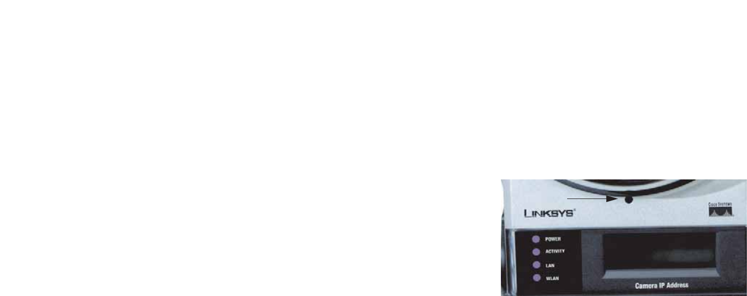
The Camera has a LCD screen that indicates the Camera’s current IP address and whether it is a fixed or dynamic
address. If the Camera uses a fixed IP address, then the screen will display the word “FIXED.” If the Camera uses
a dynamic IP address, then the screen will display the word “DHCP.”
The built-in microphone is located approximately one inch below the LCD screen, in the middle of the Camera’s
front panel. It has a range of approximately 9 feet (3 meters), depending on environmental conditions.
Camera LEDs
The Camera has four LEDs to let you know how the Camera is functioning.
POWER Amber. The POWER LED lights up when the Camera is powered on. It flashes for about 10-15
seconds while the Camera is initializing.
ACTIVITY Green. The ACTIVITY LED flashes when there is activity.
LAN Green. The LAN LED lights up when there is a connection to a wired network. It flashes when
data is transmitted to or received from the wired network.
WLAN Green. The WLAN LED lights up when there is a connection to a wireless network. It flashes
when data is transmitted to or received from the wireless network.
Figure 2-1: Camera LEDS, LCD Screen and
Built-in Microphone
Built-in
Microphone

7
Chapter 2: Getting to Know the PTZ Internet Camera
Camera Ports and Button
Wireless-G PTZ Internet Camera with Audio
Camera Ports and Button
The Camera features three ports and a Reset button on the bottom panel.
POWER The POWER port is where you will connect the power adapter.
MIC IN The MIC IN port is where you will connect the 2.5 mm input jack of your external microphone
(optional).
RESET The RESET button is what you will press if you need to reset the Camera. Insert a paper clip
into the opening next to the Ethernet port. Then press the button and hold it in for five seconds.
IMPORTANT: Resetting the Camera will erase all of
your settings, such as encryption information, and
replace them with the factory defaults. Do not reset
the Camera if you want to retain these settings.

8
Chapter 3: Connecting the PTZ Internet Camera
Overview
Wireless-G PTZ Internet Camera with Audio
Chapter 3: Connecting the PTZ Internet Camera
Overview
Before you set up the Camera, connect it to a wired or wireless network. Proceed to the appropriate section for
your setup.
If you need to move the Camera from a wired network to a wireless network, or vice versa, go to this section,
“Moving the Camera to a Different Network.”
Connection to a Wired Network for Setup
1. Attach the antenna.
2. Connect the Ethernet network cable to your network switch or router.
3. Connect the other end of the cable to the Ethernet port on the Camera.
4. Connect the power adapter to the Power port on the Camera.
5. Plug the power adapter into an electrical outlet.
The Camera’s Ready LED flashes while the Camera is initializing. The Camera is ready for use when the Ready
and Ethernet LEDs are solidly lit.
Proceed to “Chapter 5: Setting up and Mounting the Wireless-G Internet Camera.”
NOTE: You MUST connect the Camera to a PC, router, or switch using the Ethernet network
cable BEFORE powering on the Camera. Otherwise, the Camera will not function.

9
Chapter 3: Connecting the PTZ Internet Camera
Connection to a Wireless Ad-Hoc Network for Setup
Wireless-G PTZ Internet Camera with Audio
Connection to a Wireless Ad-Hoc Network for Setup
1. Make sure your computer has the following wireless settings:
• SSID - linksys
• Network Mode - Ad-Hoc
• Channel - 6
• WEP - Disabled
2. Attach the antenna.
3. Connect the power adapter to the Power port on the Camera.
4. Plug the power adapter into an electrical outlet.
The Camera’s Ready LED flashes while the Camera is initializing. The Camera is ready for use when the Ready
and Wireless LEDs are solidly lit.
Proceed to “Chapter 5: Setting up and Mounting the Wireless-G Internet Camera.”
Moving the Camera to a Different Network
When you move the Camera from a wired network to a wireless network, or vice versa, you must power off the
Camera before connecting to the new network. Proceed to the appropriate instructions.
To move the Camera from a wired network to a wireless network, follow these instructions:
1. Unplug the power adapter from the Camera.
2. Unplug the Ethernet network cable from the Camera.
3. Re-connect the power adapter to the Power port on the Camera.
The Camera’s Ready LED flashes while the Camera is initializing. The Camera is ready for use when the Ready
and Wireless LEDs are solidly lit.

10
Chapter 3: Connecting the PTZ Internet Camera
Moving the Camera to a Different Network
Wireless-G PTZ Internet Camera with Audio
To move the Camera from a wireless network to a wired network, follow these instructions:
1. Unplug the power adapter from the Camera.
2. Connect the Ethernet network cable to your PC, router, or switch.
3. Connect the other end of the cable to the Ethernet port on the Camera.
4. Re-connect the power adapter to the Power port on the Camera.
The Camera’s Ready LED flashes while the Camera is initializing. The Camera is ready for use when the Ready
and LAN LEDs are solidly lit.
11
Chapter 4: Setting up and Mounting the Wireless-G Internet Camera
Setup Wizard
Wireless-G PTZ Internet Camera with Audio
Chapter 4: Setting up and Mounting the Wireless-G
Internet Camera
Setup Wizard
The Wireless-G Internet Camera Setup Wizard will guide you through the installation and configuration procedure.
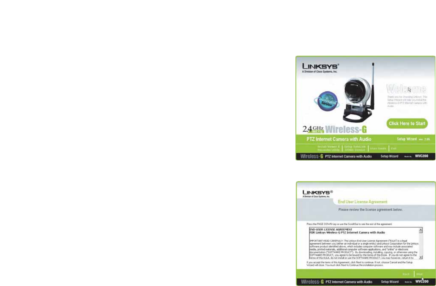
1. Insert the Setup CD-ROM into your CD-ROM drive. The Setup Wizard should run automatically, and the
Welcome screen should appear. If it does not, click the Start button and choose Run. In the field provided,
enter D:\wvc210.exe (if “D” is the letter of your CD-ROM drive).
•Setup. Click the Click Here to Start button to begin the installation process.
•Install Viewer & Recorder Utility. Click this button to install the Camera’s Viewer & Recorder Utility on
your PC.
•Setup SoloLink DDNS Service. Click the Setup SoloLink DDNS Service button to configure and use
Linksys’s Dynamic Domain Name System (DDNS) service.
•User Guide. Click this button to open the PDF file of this User Guide.
•Exit. Click the Exit button to exit the Setup Wizard.
2. The next screen shows the End User License Agreement. Read through this and, if you accept the terms of the
Agreement, click Next to continue.
Figure 4-2: The End User License Agreement
Figure 4-1: Setup Wizard - Welcome Screen
12
Chapter 4: Setting up and Mounting the Wireless-G Internet Camera
Setup Wizard
Wireless-G PTZ Internet Camera with Audio
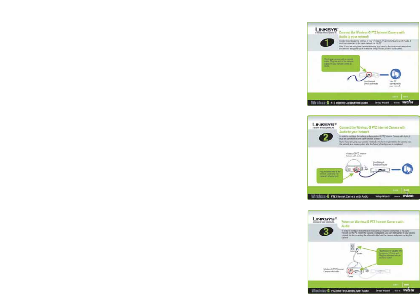
3. The next three screens show how to connect the Camera to your network, starting with connecting a network
cable to your network’s router or switch. Once you have done this, click Next.
4. Next, connect that network cable to the Camera’s RJ-45 port, as shown. Once you have done this, click Next.
5. Once that is done, connect the Camera’s power cable to the Camera’s power port, as shown. Once you have
done this, click Next.
Figure 4-4: Connect Network Cable to Camera
Figure 4-3: Connect Network Cable to Network
Figure 4-5: Connect Power to Camera
13
Chapter 4: Setting up and Mounting the Wireless-G Internet Camera
Setup Wizard
Wireless-G PTZ Internet Camera with Audio
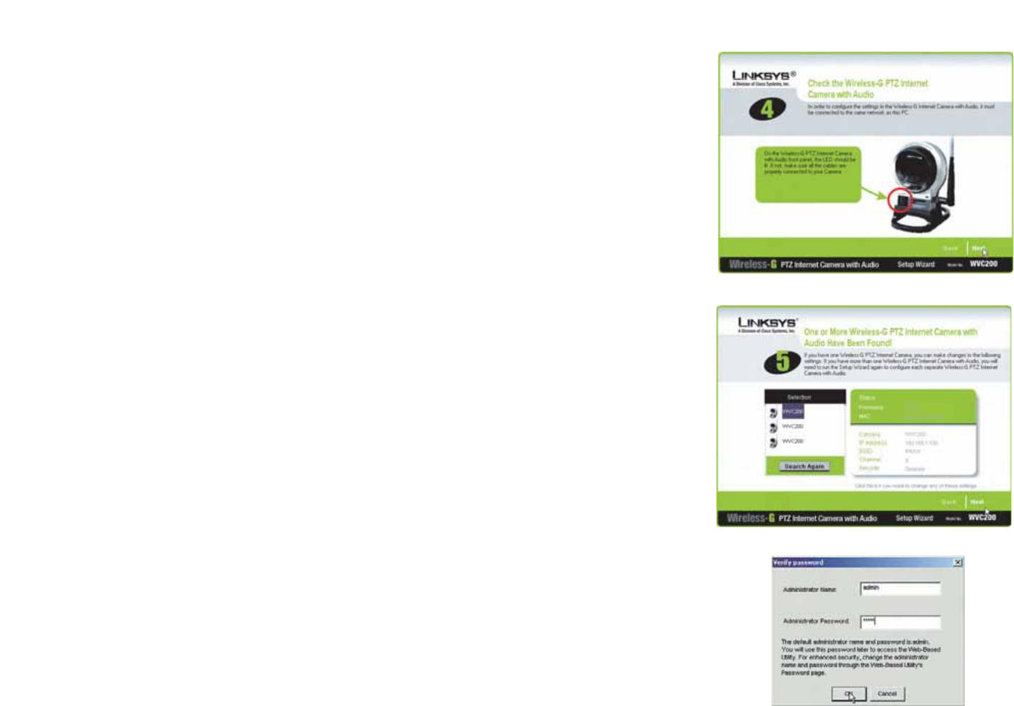
6. Now, check the Camera’s LEDs to verify that they’re functioning properly. Then, click Next.
7. The Wizard will now display a list of Internet Cameras on your network, along with the status information for
the Camera whose name is highlighted. In the Selection box, click the name of the Camera you are currently
installing. Write down the IP address of the Camera, so you can use it to access the Web-based Utility later.
Click the Next button.
8. For increased network security, enter a name and password for administrator access to the Camera. In
lowercase letters, enter admin in the Administrator Name and Administrator Password fields. (You can
change these settings through the Camera’s Web-based Utility later.) Then, click the OK button.
Figure 4-6: Check LEDs screen
Figure 4-7: Network Cameras Found Screen
Figure 4-8: Wizard Login Screen
14
Chapter 4: Setting up and Mounting the Wireless-G Internet Camera
Setup Wizard
Wireless-G PTZ Internet Camera with Audio
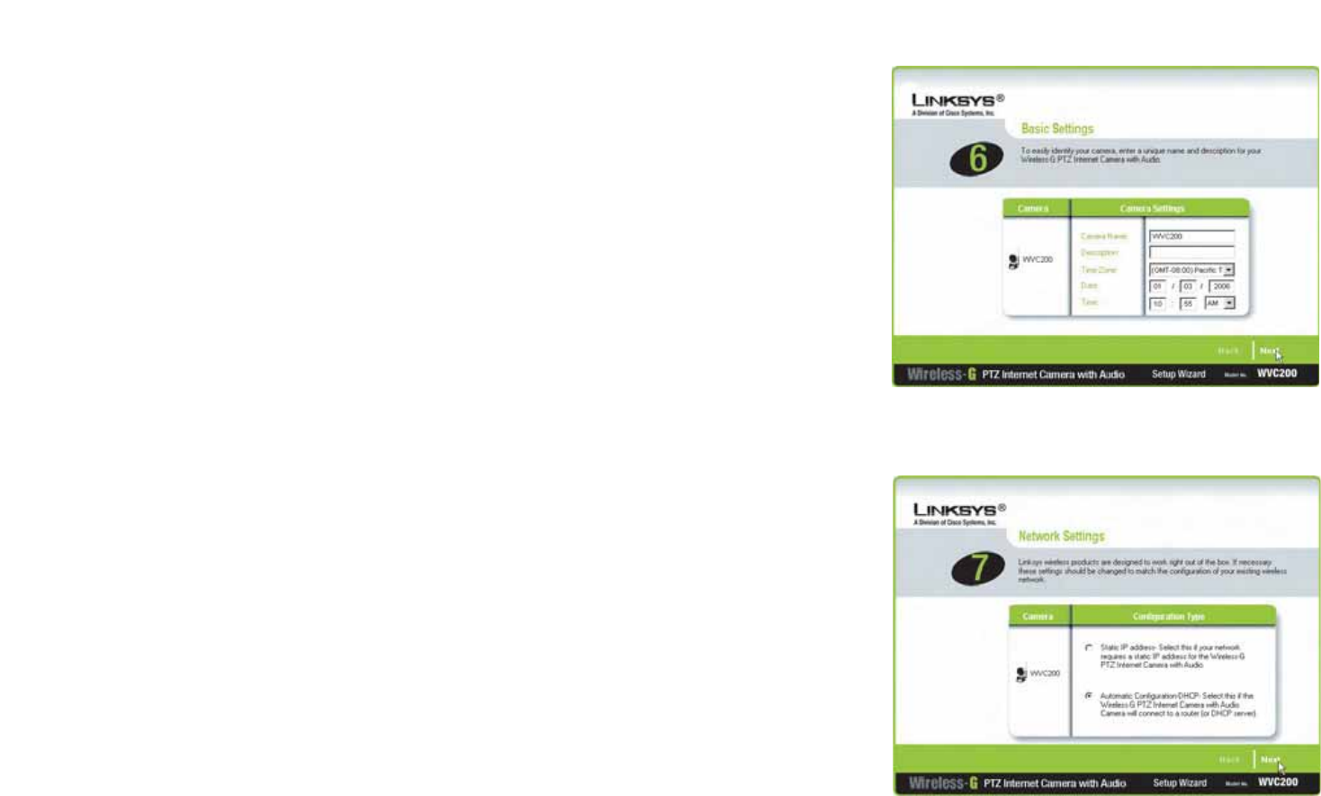
9. On the Basic Settings screen, you can alter the following settings:
•Camera Name. You can give the Camera a unique name. Memorable names are helpful, especially if you
are using multiple Cameras on the same network. It should have 15 characters or fewer.
•Description. You may enter additional information, such as location, in this field. It has a maximum length
of 32 characters.
•Time Zone. Select the time zone for the Camera’s location.
•Date. Enter today’s date in the fields provided.
•Time. Enter the current time in the fields provided.
When you have finished making your changes, click Next.
10. If you need to assign a static IP address to the Camera, select Static IP address. If your network has a DHCP
server, keep the default setting, Automatic Configuration-DHCP.
Then, click Next.
Figure 4-9: Basic Settings Screen
Figure 4-10: Network Settings Screen
15
Chapter 4: Setting up and Mounting the Wireless-G Internet Camera
Setup Wizard
Wireless-G PTZ Internet Camera with Audio
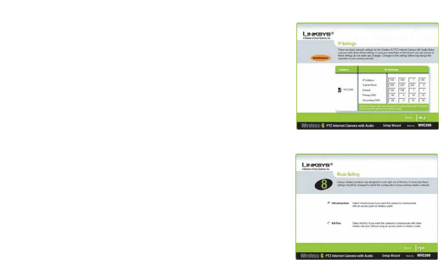
11. If you selected Automatic Configuration-DHCP, proceed to the next step.
If you selected Static IP Address, the IP Settings screen will appear. Enter an IP Address, Subnet Mask, and
Default Gateway appropriate for your network. You must specify an IP Address and Subnet Mask on this
screen. If you are unsure about the Default Gateway, it is better to leave this field blank. Then complete the
Primary DNS and/or Secondary DNS fields. You must enter at least one DNS address, which can be obtained
from your ISP. Click Next to continue.
12. The Mode Setting screen will appear next. Click the Infrastructure radio button if you want the Camera to
communicate using an access point or wireless router. Click the Ad-Hoc radio button if you want the Camera
to communicate without using an access point or wireless router. After making your selection, click Next.
Figure 4-11: IP Settings Screen
Figure 4-12: Mode Settings Screen
16
Chapter 4: Setting up and Mounting the Wireless-G Internet Camera
Setup Wizard
Wireless-G PTZ Internet Camera with Audio
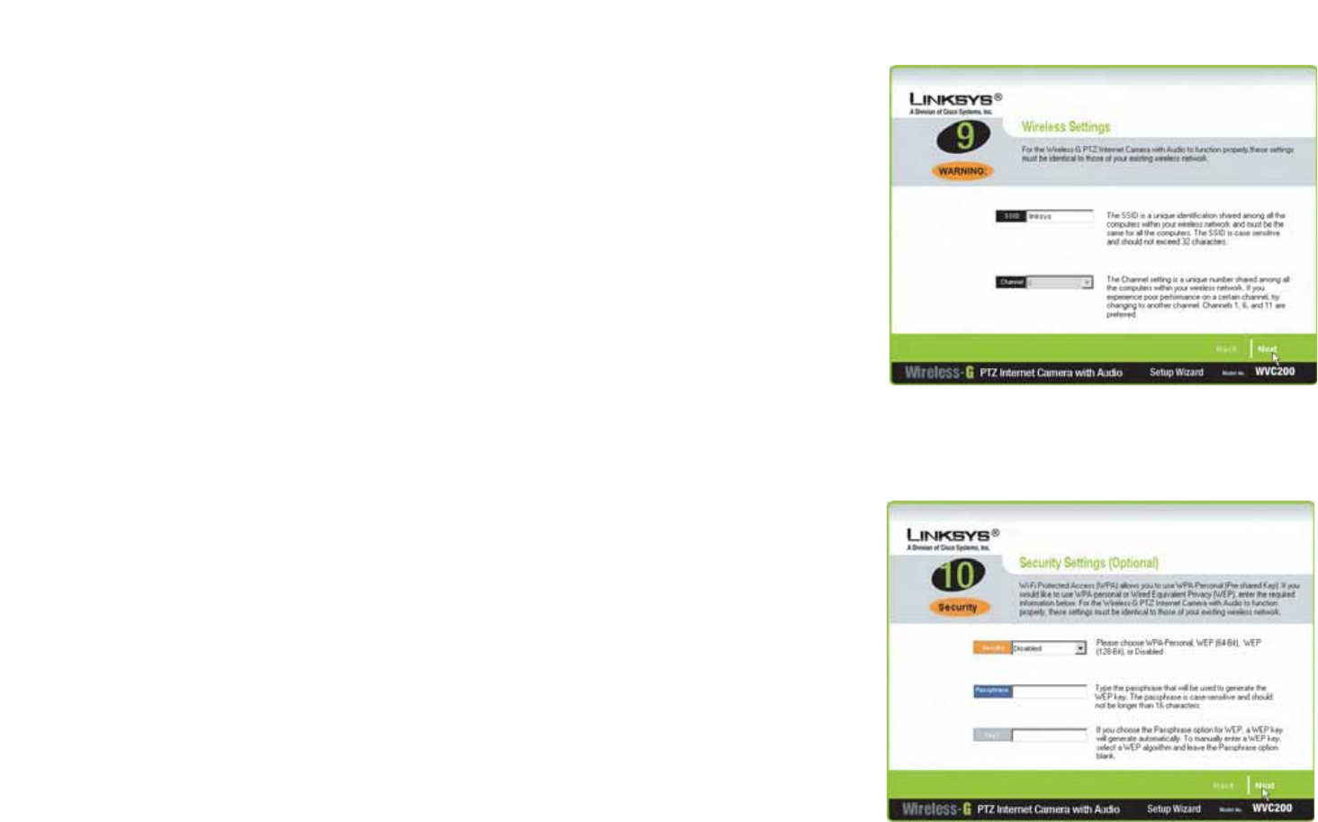
13. The Wireless Settings screen will appear, so you can change the wireless settings. Enter your wireless
network’s SSID or network name. If you chose Ad-Hoc mode, select the channel at which the network
broadcasts its wireless signal.
•SSID. The SSID must be identical for all devices in a wireless network. It is case-sensitive and should
have 32 alphanumeric characters or fewer. (You can use any keyboard character, but do not use any
spaces.)
•Channel. If you set the Camera to Ad-Hoc mode, select the appropriate channel from the drop-down
menu. All devices in your wireless ad-hoc network must use the same channel in order to function
correctly.
Then, click the Next button.
The Security Settings screen will appear. If your network has WEP encryption enabled, then select the level
of WEP encryption and enter a Passphrase. If you want to manually enter a WEP key, leave the Passphrase
field blank, and enter the WEP key in the Key 1 field. If your network has WPA-Personal encryption enabled,
enter a WPA Shared Key. If your network has WEP and WPA-Personal encryption disabled, keep the default
setting, Disabled.
•WEP. To enable WEP encryption, select 64-Bit Keys or 128-Bit Keys from the drop-down menu. Then
enter a Passphrase. If you want to manually enter a WEP key, leave the Passphrase field blank.
•Passphrase. If you enabled WEP encryption, you can enter a Passphrase, so a WEP key will be
automatically generated. If you want to manually enter a WEP key, leave the Passphrase field blank. The
Passphrase is case-sensitive and should have 16 alphanumeric characters or fewer. It must match the
passphrase of your wireless network and is compatible with Linksys wireless products only. (You will
have to enter the WEP key(s) manually on any non-Linksys wireless products.)
•Key 1. If you want to manually enter a WEP key, complete this field. If you are using 64-bit WEP
encryption, then the key must consist of exactly 10 hexadecimal characters. If you are using 128-bit WEP
encryption, then the key must consist of 26 hexadecimal characters. Valid hexadecimal characters are
“0” through “9” and “A” through “F”.
•WPA-Personal. To enable WPA-Personal encryption, enter a WPA Shared Key from 8 to 63 characters.
•WPA Shared Key. If you enabled WPA-Personal encryption, enter the WPA Shared Key that you’re using
on your wireless network.
Click the Next button.
Figure 4-13: Wireless Settings Screen
Figure 4-14: Security Settings Screen
17
Chapter 4: Setting up and Mounting the Wireless-G Internet Camera
Setup Wizard
Wireless-G PTZ Internet Camera with Audio
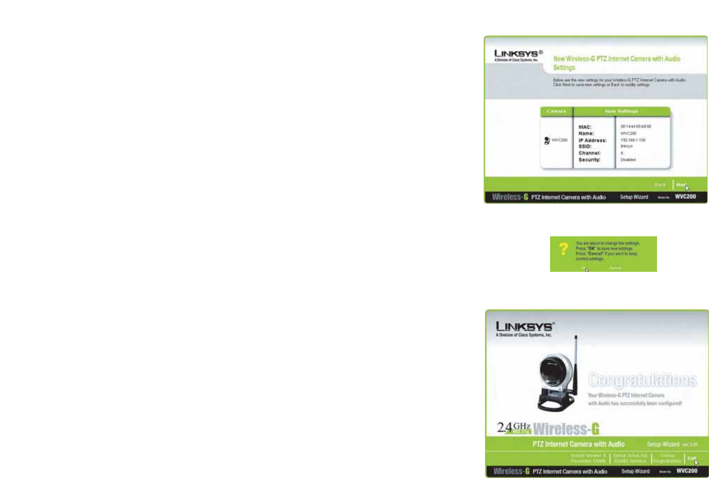
Review your settings before the Setup Wizard starts to copy your files. Click the Next button to continue.
14. If you want to save the new settings, click the OK button. If you want to cancel your changes, click the Cancel
button.
15. After the files have been successfully copied, the Congratulations screen will appear.
•Install Viewer & Recorder Utility. Click this button to install the Camera’s Utility on your PC.
•Setup SoloLink DDNS Service. Click the Setup SoloLink DDNS Service button to set up and configure
the Linksys Dynamic Domain Name System (DDNS) service.
•Exit. Click the Exit button if you want to install the Camera’s Utility later.
Continue to the “Placement Options” section.
Figure 4-15: Review New Settings Screen
Figure 4-17: Congratulations Screen
Figure 4-16: Confirmation Screen
18
Chapter 4: Setting up and Mounting the Wireless-G Internet Camera
Placement Options
Wireless-G PTZ Internet Camera with Audio
Placement Options
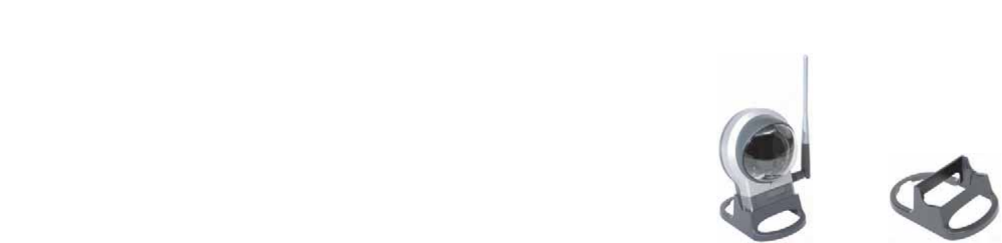
There are two ways to place the Camera. The first way is to place the Camera horizontally on a surface using the
included stand. The second way is to mount the camera on a wall using an optional wall mount stand.
Stand Option
1. The Camera includes a Camera Desktop Stand. Insert the bottom end of the camera into the Stand.
2. Place the Camera, and adjust its aim accordingly.
Wall Mount Option
The Camera has a standard camera mount that allows you to attach it to an optional wall mount stand.
1. Determine where you want to mount the Camera. Attach the wall mount stand to the wall.
2. Attach the camera to the wall mount.
3. Adjust the Camera’s aim and focus accordingly.
Proceed to the next section, “Audio Option.”
Audio Option
If you want to use your own microphone instead of the Camera’s built-in microphone, then follow these
instructions:
1. Connect the 2.5 mm input jack of your microphone to the Camera’s MIC IN port on its bottom panel. The built-
in microphone will automatically be disabled.
2. Place the external microphone in an appropriate location.
The installation of the Wireless-G Internet Camera is complete. Go to “Chapter 6: Installing the
Wireless-G Internet Camera Viewer & Recorder Utility.”
If advanced users wish to access the Camera through its Web-based Utility, then proceed to “Chapter 8:
Using the Wireless-G Internet Camera Web-based Utility.”
Figure 4-18: Stand Option Figure 4-19: Camera
Desktop Stand
19
Chapter 5: Installing and Using the Internet Camera Viewer & Recorder Utility
Overview
Wireless-G PTZ Internet Camera with Audio
Chapter 5: Installing and Using the Internet Camera Viewer &
Recorder Utility
Overview
This chapter will instruct you on how to install and use the Internet Camera Viewer & Recorder Utility on your PC.
The Utility allows you to easily view and record the Camera’s video.
If another Internet Camera Viewer & Recorder Utility has already been installed on your PC, you should uninstall it
before installing this Internet Camera Viewer & Recorder Utility.
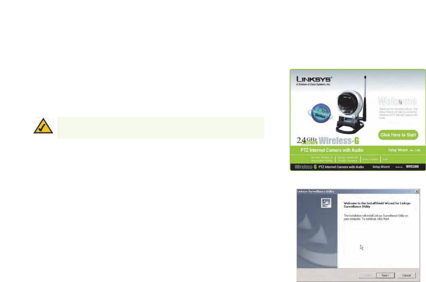
Installing the Viewer & Recorder Utility
1. On the Welcome or Congratulations screen of the Setup Wizard, click the Install Viewer & Recorder Utility
button.
2. The Welcome screen will appear. Click the Next button to proceed.
Figure 5-1: Install Viewer & Recorder Utility Screen
Figure 5-2: Install Viewer & Recorder Utility -
Welcome Screen
NOTE: To view video using a web browser, you must use Internet Explorer version 5.5 or
higher. The View Video feature will not work with other web browsers. If you do not use
Internet Explorer v5.5, use the Viewer & Recorder Utility instead.
20
Chapter 5: Installing and Using the Internet Camera Viewer & Recorder Utility
Installing the Viewer & Recorder Utility
Wireless-G PTZ Internet Camera with Audio
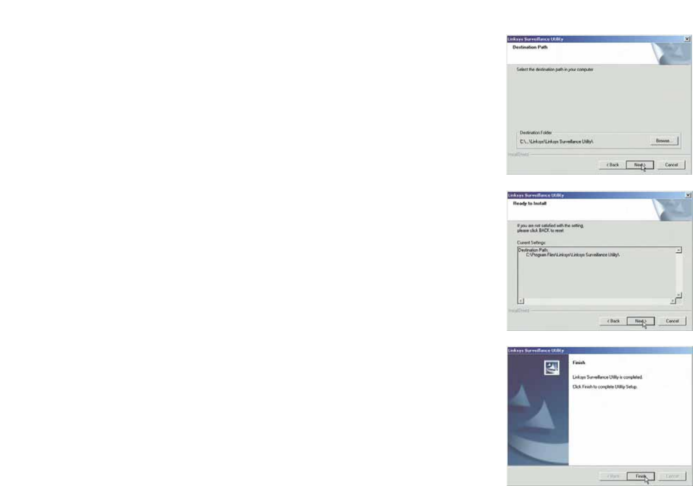
3. The Choose Destination Location screen will appear. To install the Viewer & Recorder Utility files in the default
folder, click the Next button. To select a different folder, click the Browse button and follow the on-screen
directions.
4. The Select Program Folder screen will appear. To add program icons to the default folder, click the Next
button. If you wish, you can rename the default folder. To add program icons to an existing folder, select one
from the Existing Folders listed, and then click the Next button.
5. When the setup is complete, click the OK button.
To learn how to use the Viewer & Recorder Utility, proceed to the next section, Using the Viewer &
Recorder Utility.
To set up the Linksys SoloLink Service, go to Chapter 6: Setting up the Linksys SoloLink DDNS Service.
Advanced users: If you want to use the Camera’s Web-based Utility, go to Chapter 7: Using the
Wireless-G Internet Camera Web-based Utility.
Figure 5-3: Choose Destination Location Screen
Figure 5-4: Select Program Folder Screen
Figure 5-5: Setup Complete Screen
21
Chapter 5: Installing and Using the Internet Camera Viewer & Recorder Utility
Using the Viewer & Recorder Utility
Wireless-G PTZ Internet Camera with Audio
Using the Viewer & Recorder Utility
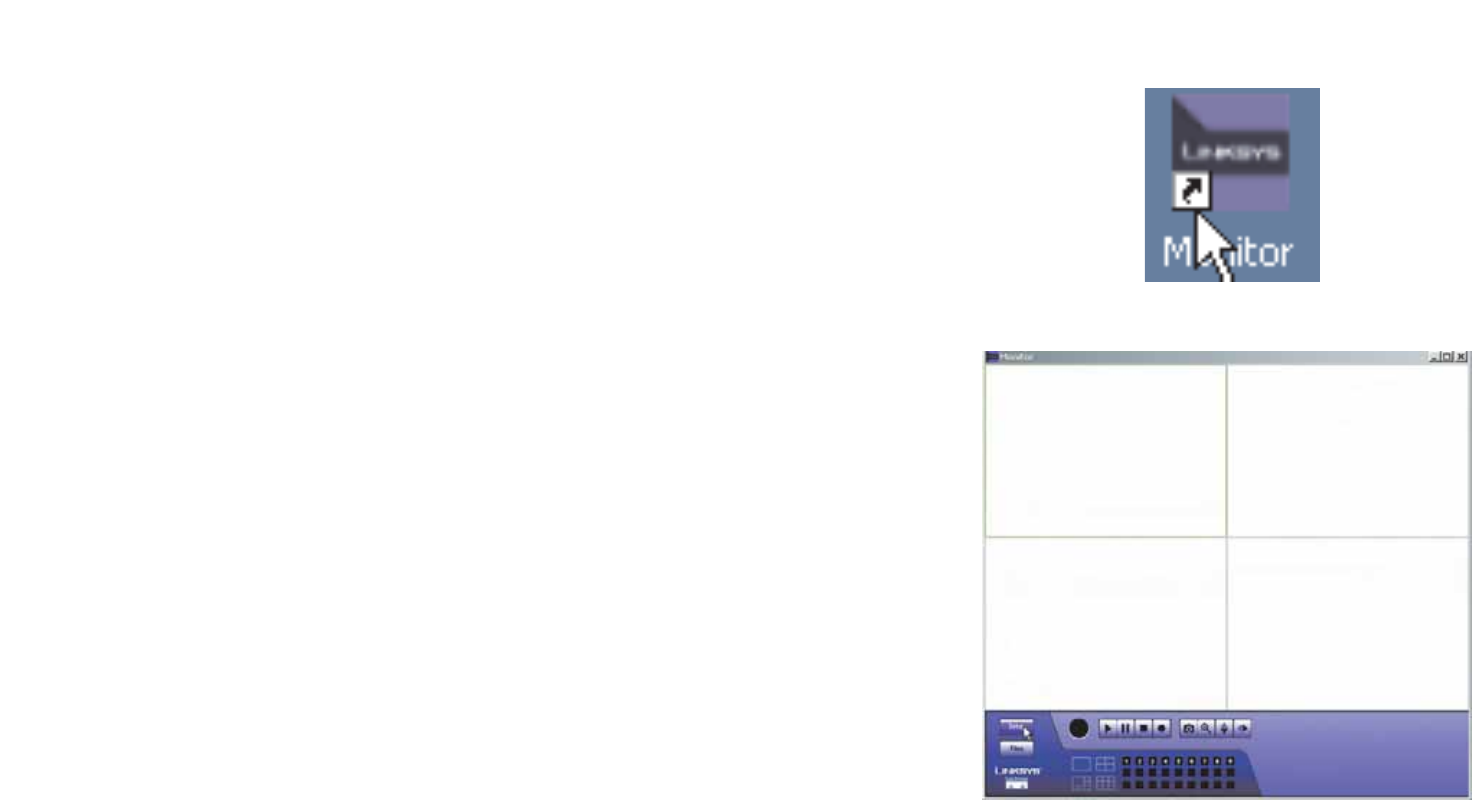
After the Viewer & Recorder Utility has been installed, the Viewer & Recorder Utility icon will be displayed in two
locations, one on your desktop and one in the system tray of your desktop’s taskbar.
There are two ways to open the Viewer & Recorder Utility:
• Double-click the icon on your desktop (the icon acts as a shortcut)
• Right-click the icon in the system tray, and then click Monitor.
You will see the Utility’s main screen. From this screen, you can control Cameras, view video, and schedule
recordings.
To minimize any of the Utility’s screens, click the X button in the upper right-hand corner. To request help
information, click the ? button in the upper right-hand corner. To close the Utility, right-click the Viewer &
Recorder Utility icon in your desktop’s system tray. Then click Exit.
Figure 5-6: Viewer & Recorder Utility Icon
Figure 5-7: Main Screen
22
Chapter 5: Installing and Using the Internet Camera Viewer & Recorder Utility
Using the Viewer & Recorder Utility
Wireless-G PTZ Internet Camera with Audio
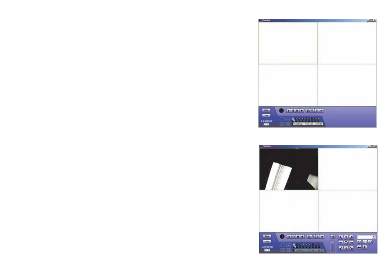
Selecting A Camera
When you first access the Utility’s main screen, you will want to select a camera to view and manage the
camera’s video. To select a camera, click one of the numbered buttons, 1-9, on the bottom of the screen.
Selecting that number, will bring up the camera assigned to it, which is described later.
Once you’ve selected the camera, more buttons will appear along with the video feed.
Figure 5-8: Selecting Camera
Figure 5-9: Camera Selected
23
Chapter 5: Installing and Using the Internet Camera Viewer & Recorder Utility
Using the Viewer & Recorder Utility
Wireless-G PTZ Internet Camera with Audio
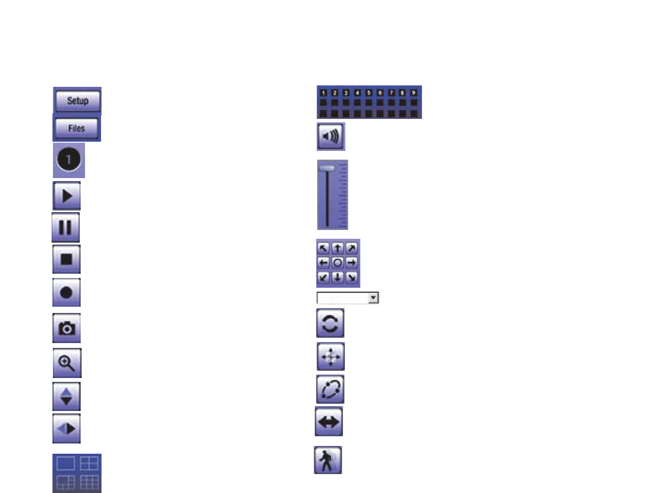
Using the Main Screen
Navigation through the main screen is performed through the icons at the bottom. Here is a list of the icons and a
short explanation of each
Setup - Clicking this button opens the Setup
Window.
Files - Clicking this button opens File Finder, which
allows you to browse through previously saved
recordings.
Play - Use this to re-start viewing, after using the
Stop or Pause button.
Camera Setting - This indicates the Channel (or
Camera) setting used by the Camera within the Utility.
Pause - Clicking this pauses the video playback.
Stop - This will terminate the connection to the camera,
halting both the viewing and the recording (if in progress).
Record - Clicking this begins recording a video stream.
While recording, this button will be blue. To stop
recording, click the Stop button.
Snapshot - Clicking this takes a image of the current
video.
Zoom - Clicking this magnifies a section of the window.
Click the icon and then click the portion of the screen you
want to magnify. Click the icon again to return
magnification to normal.
Flip - Click this to have the image swapped top-to-bottom.
Mirror - Click this to have the image swapped left-to-
right.
Screen Layout - Select the number of Channels
(Cameras) to be displayed on screen
Speaker Volume - When audio is available, raising or lowering this bar
will change the volume.
Mute - When audio is available, clicking this will silence the audio.
Camera Selection - Clicking the camera number you wish to
view on the main screen.
Position- Clicking these arrows will position the camera, with the center
icon returning the camera to a neutral position.
Preset Position - Select the desired preset position from the drop-down
list. Set these positions from the Set Preset Position button, below.
Refresh - Clicking this button updates the Preset Position list, in the
event it was changed by an Administrator.
Set Preset Position - Clicking this button sets a preset camera position,
which is explained further in Setting Presets.
Patrol - Move through the Preset positions in the sequence defined by
the Camera Administrator.
Auto Pan - Clicking this button moves the camera from left to right from
its current position then returns the camera to the same position it was in
before you clicked the Auto Pan button.
Motion Detection - Clicking this button enables Motion Detection and
moves the camera to your preset motion detection camera position.
24
Chapter 5: Installing and Using the Internet Camera Viewer & Recorder Utility
Using the Viewer & Recorder Utility
Wireless-G PTZ Internet Camera with Audio
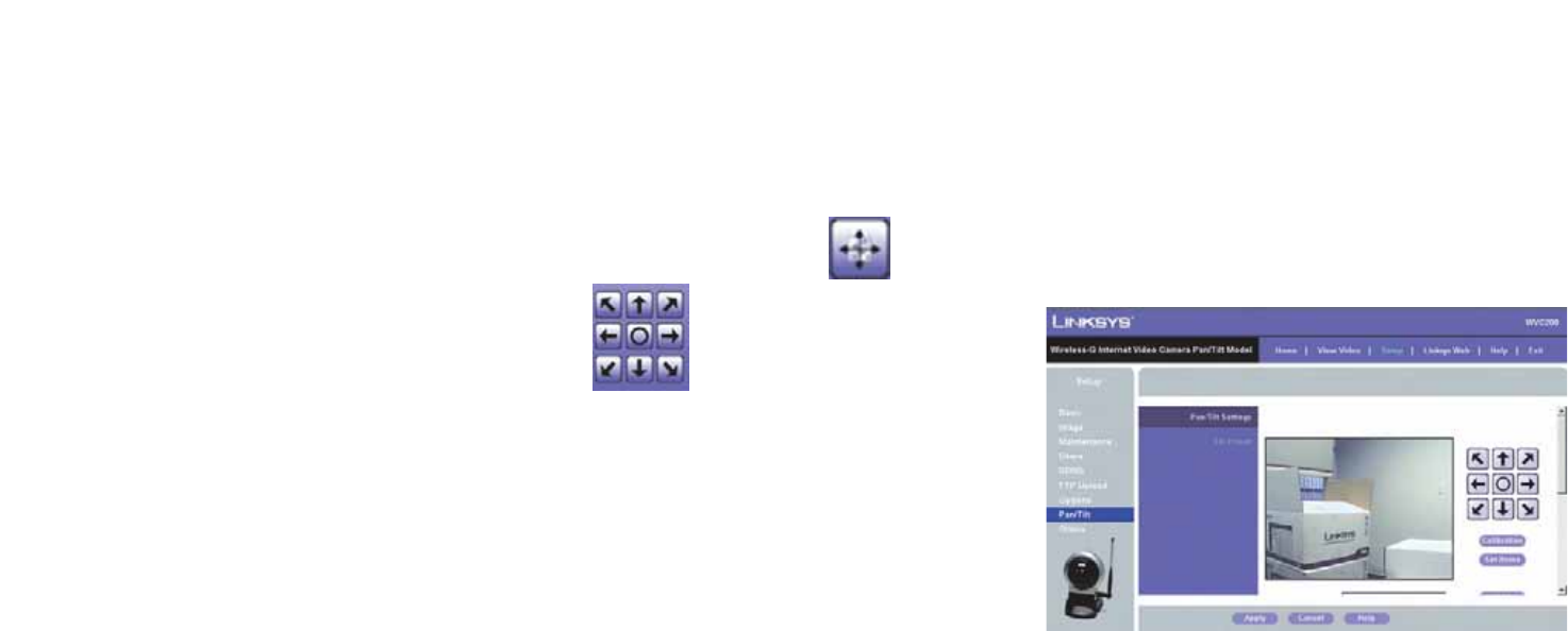
Setting Presets
Preset camera positions can have various uses, in addition to being a part of the Patrol function. To preset camera
positions, do the following:
1. Click the Set Preset Position button on the View Video page to set the position.
2. Position the camera with the Positioning buttons.
3. You see the Set Preset Position screen, select the Preset Number, enter a Preset Name, then click the
Add button.
4. Click the Apply button when finished or the Cancel button if you decide not to set the Preset Position.
Figure 5-10: Set Preset Position Screen
25
Chapter 5: Installing and Using the Internet Camera Viewer & Recorder Utility
Setting Up the Camera
Wireless-G PTZ Internet Camera with Audio
Setting Up the Camera
The Camera’s setup functions are performed by clicking the Setup button on the Main screen. This will open the
Setup screen.
Several setup options appear on the left-hand side of the screen. They are Camera Setup, Recording Schedule,
and Preferences. Each of these options is described below.
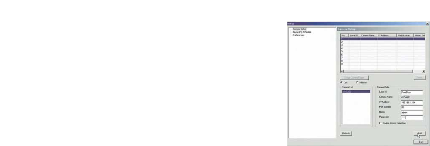
Camera Setup
Adding a Camera
You can add one of the nine cameras displayed from the Main screen by doing the following:
1. Select the LAN or Internet radio buttons, depending on if this camera is situated on your local network or
accessed over the Internet
2. Enter the camera’s data into the Camera Data fields:
Local ID. Enter a name for the camera (this name will be included in the name of recorded video files).
IP Address. Enter the camera’s IP Address here.
Port Number. Enter the port number assigned to this camera.
User (Name). Enter the user name set to this camera when it was setup.
Password. Enter the password set to this camera when it was setup.
3. Select Enable Motion Detection if you wish this to be enabled.
4. Click the line you wish to assign to the camera in the box at the top of the screen. After the camera has been
added, you can view it by clicking its assigned number on the Main screen.
5. Click the Add button to add the camera.
Deleting a Camera
You can delete any of the nine cameras displayed from the Setup screen by doing the following:
1. Select the camera you want to delete from the list in the box at the top of the screen.
2. Click the Delete button.
Figure 5-11: Camera Setup Screen
26
Chapter 5: Installing and Using the Internet Camera Viewer & Recorder Utility
Setting Up the Camera
Wireless-G PTZ Internet Camera with Audio
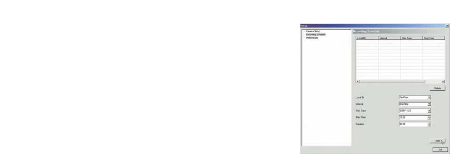
Recording Schedule
Scheduling a Recording
You can record video while watching, or schedule recordings to occur when you are absent. Recordings are
stored in a standard Microsoft ASF file format, and can be played using Microsoft’s Windows Media Player, or in
a standard AVI (MJPEG) file format.
To set the Recording Preferences:
1. Enter the recording schedule’s data into the drop-down fields on this screen:
Local ID.
Interval. Select when or how often you want this recording to occur.
Start Date. From the calendar that appears when you click the drop-down menu, select the date when this
schedule will begin.
Start Time. Enter the time when this schedule will begin.
Duration. Enter the amount of time before this schedule expires.
2. Click the line you wish to assign to the schedule in the box at the top of the screen.
3. Click the Add button to schedule the recording.
Deleting a Schedule
You can delete any of the nine schedules displayed on this screen by doing the following:
1. Select the camera you want to delete from the list in the box at the top of the screen.
2. Click the Delete button.
Click the Exit button to close the Setup screen.
Figure 5-12: Recording Schedule Screen
27
Chapter 5: Installing and Using the Internet Camera Viewer & Recorder Utility
Setting Up the Camera
Wireless-G PTZ Internet Camera with Audio
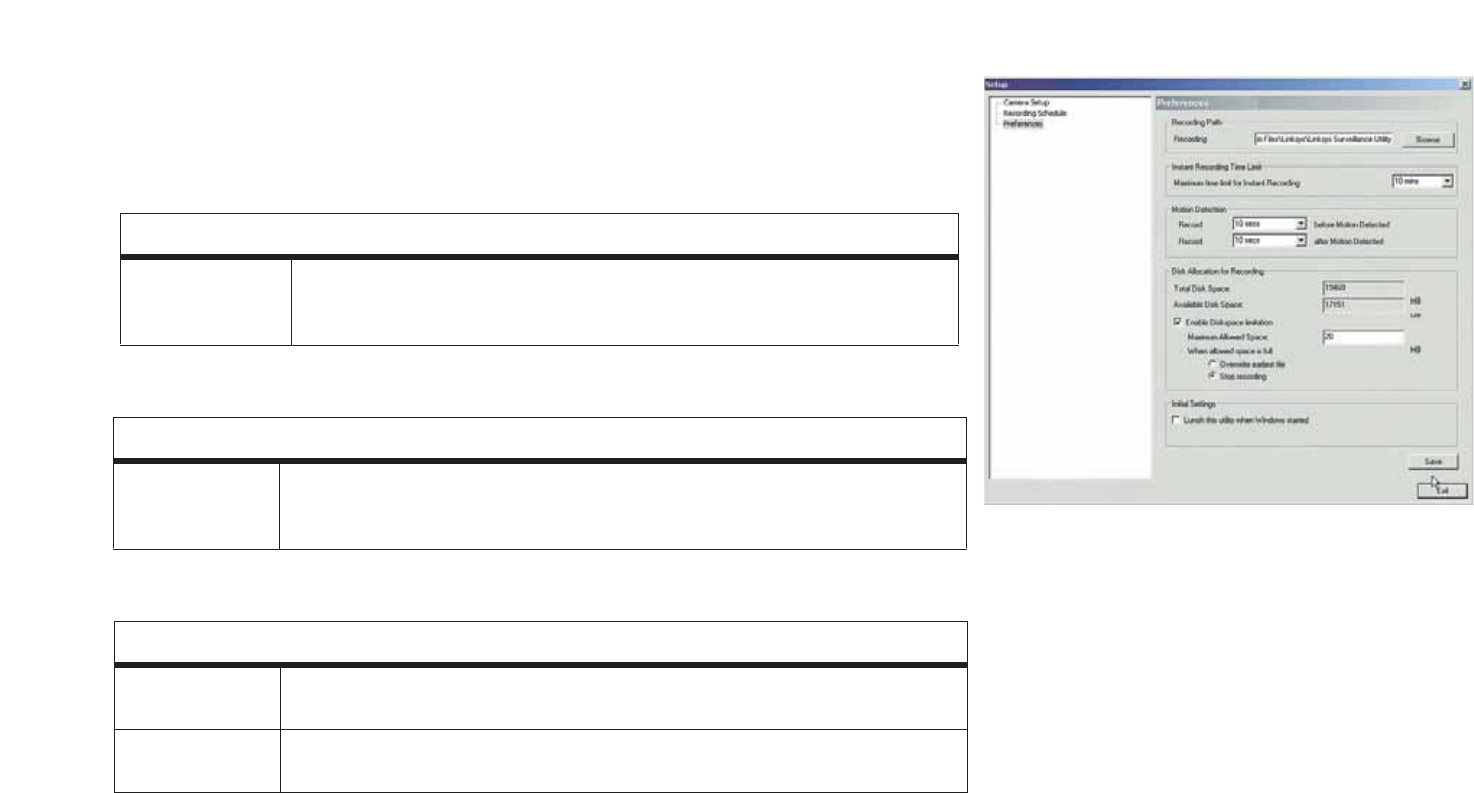
Preferences
Setting Preferences
Refer to the following tables when changing preferences.
Recording Path
Recording This is the Drive and Folder on your PC where recorded files will be saved. The
default location is C:\Program Files\Linksys\Linksys Surveillance Utility\Local ID\File
Type. You can also click the Browse button to select the desired drive and folder.
Instant Recording Time Limit
Maximum time
limit for Instant
Recording
This sets the maximum size of a recording. (Recordings are started by clicking the
Record button on the Main screen.)
Motion Detection
Record before
Motion Detected Set the time so the Utility will start recording a certain time before the Utility detects
motion in a Camera's field of view.
Record after
Motion Detected Set the time so the Utility will stop recording a certain time after the Utility detects
motion in a Camera's field of view.
Figure 5-13: Preferences Screen

28
Chapter 5: Installing and Using the Internet Camera Viewer & Recorder Utility
Setting Up the Camera
Wireless-G PTZ Internet Camera with Audio
Once you set the preferences on this screen, click the Save button to save your changes. Clicking the Help button
will bring up helpful information about this page. Click the Exit button to close the Setup screen.
Disk Allocation for Recording
Total Disk Space This shows the total amount of storage space on your hard drive.
Available Disk
Space This shows the amount of storage space available on your hard drive.
Enable Disk Space
Limitation This feature allows you to limit the amount of space your recordings occupy on your
hard drive. Click the box for this feature and then enter the Maximum Allowed Space
in the next box. The Maximum Allowed Space is the amount of space on your hard
drive you’ll allow your recordings to take up, which should be smaller than the
available room you have left on your drive along with space for your operating system
and other programs. Plan for when that space gets full by clicking either Overwrite
Earliest File, which will delete old recordings as new ones fill the space, or Stop
Recording, which will end your recording once you fill the space. Allow a minimum of
300 MB storage space per camera. If you will be using the same drive that Windows is
installed on to store your recordings, make sure you leave at least ten percent of
available disk space free.
Initial Settings
Launch this Utility
when Windows
Started
Check this to have this utility start when Windows starts.
29
Chapter 5: Installing and Using the Internet Camera Viewer & Recorder Utility
Using File Finder
Wireless-G PTZ Internet Camera with Audio
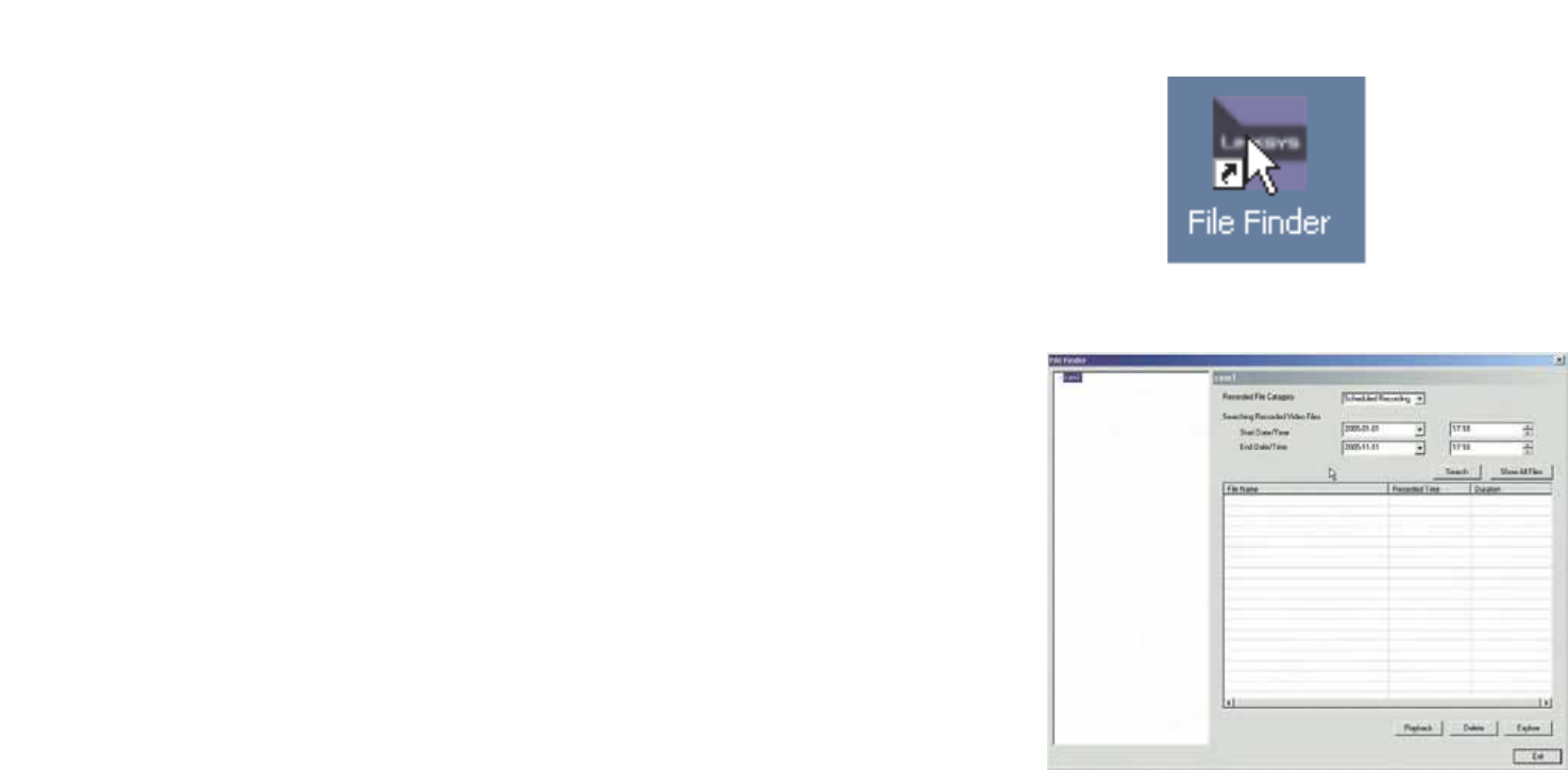
Using File Finder
To view the recordings saved for each camera you’ve assigned to the Utility, click the number of the camera and
then click the Files button. This will open the File Finder.
You can also open File Finder by clicking the icon placed on your desktop when you installed the Utility.
Recorded File Category. From this drop-down menu, select the type of recorded file you wish to view.
Searching Recorded Video Files. You can narrow your search by the time range in which the file was recorded.
Click the Search button to search for the files. To display all of your recorded files, click the Show All Files
button.
The files will be shown by name (File Name), when the file was recorded (Recorded Time), and length of file
(Duration).
To play the recorded file, click the Playback button. To delete the file, click the Delete button. If you cannot find
the file, you can browse for it by clicking the Explore button. Click the Exit button to close the File Finder.
To set up the Linksys SoloLink Service, go to Chapter 6: Setting up the Linksys SoloLink DDNS Service.
If you want to use the Camera’s Web-based Utility, go to Chapter 7: Using the Wireless-G Internet Camera
Web-based Utility.
Figure 5-14: The File Finder Desktop Icon
Figure 5-15: File Finder Screen
30
Chapter 6: Setting up the Linksys SoloLinktm DDNS Service
Overview
Wireless-G PTZ Internet Camera with Audio
Chapter 6: Setting up the Linksys SoloLinkTM DDNS Service
Overview
This chapter will briefly discuss the Linksys SoloLink DDNS Service, explain how to set up your SoloLink account,
and describe how to register additional Cameras on your SoloLink account. You need only one SoloLink account.
Once you have set up your account, you can register additional Cameras, one at a time, through each Camera’s
Web-based Utility. This way each Camera can take advantage of the SoloLink DDNS Service.
Introduction
The SoloLink DDNS (Dynamic Domain Name System) Service lets you assign a fixed host and domain name to a
dynamic Internet IP address. The instructions in this chapter will guide you through the setup needed for use of
the SoloLink DDNS Service. For the most current information about the SoloLink DDNS Service, visit
www.linksys.com/sololink. For a free, 90-day trial period of your SoloLink account, use the Access ID Card
included with the Camera.
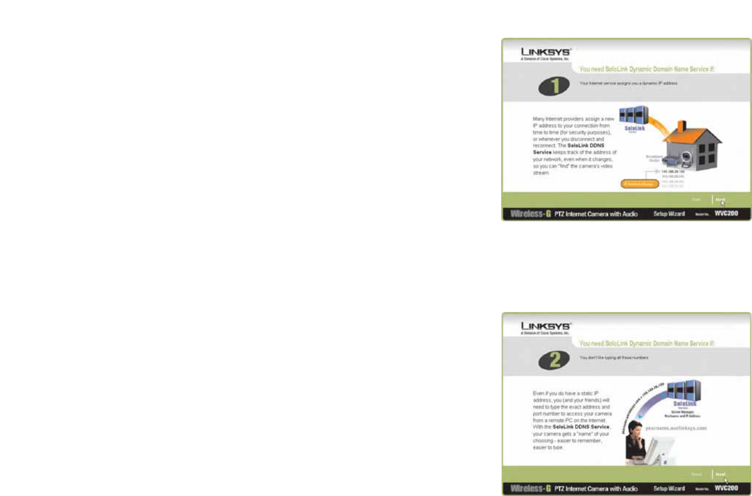
You may want to use the Linksys SoloLink DDNS Service if one of the following applies to you:
Dynamic IP Address - Your Internet service assigns you a dynamic IP address. Many Internet service providers
(ISPs) assign a new IP address to your connection from time to time (for security purposes), or whenever you
disconnect and reconnect. The SoloLink service keeps track of your network’s address, even when it changes, so
you can “find” the Camera.
Convenience - There are a couple of ways the SoloLink service can be convenient. If you have a static IP address,
you can use the SoloLink service to enter a “name” and port number for remote access of the Camera via the
Internet. There’s no need to type an entire IP address. For example, you can give a Camera a “name” such as
cam1.myhouse.ourlinksys.com.
Also, some DDNS services require your PC to continuously run software that lets them keep track of your IP
address. If your PC isn’t powered on when your IP address changes, you won’t be able to find the Camera on the
Internet. The SoloLink service keeps track of where the Camera is.
Setup Wizard for the SoloLink DDNS Service
1. On the Welcome or Congratulations screen of the Setup Wizard, click the Setup SoloLink DDNS Service
button. Figure 6-1: SoloLink Welcome Screen
31
Chapter 6: Setting up the Linksys SoloLinktm DDNS Service
Setup Wizard for the SoloLink DDNS Service
Wireless-G PTZ Internet Camera with Audio
2. The next screen explains why you would want to use the SoloLink DDNS Service if your network is using a
dynamic IP address. Click the Next button.
3. The next screen explains why you would find the SoloLink DDNS Service convenient if you would prefer to
access the Camera using a name rather than a series of numbers (its IP address). Click the Next button to
continue.
Figure 6-3: SoloLink for Convenience Screen
Figure 6-2: SoloLink for Dynamic IP Address Screen
32
Chapter 6: Setting up the Linksys SoloLinktm DDNS Service
Setup Wizard for the SoloLink DDNS Service
Wireless-G PTZ Internet Camera with Audio
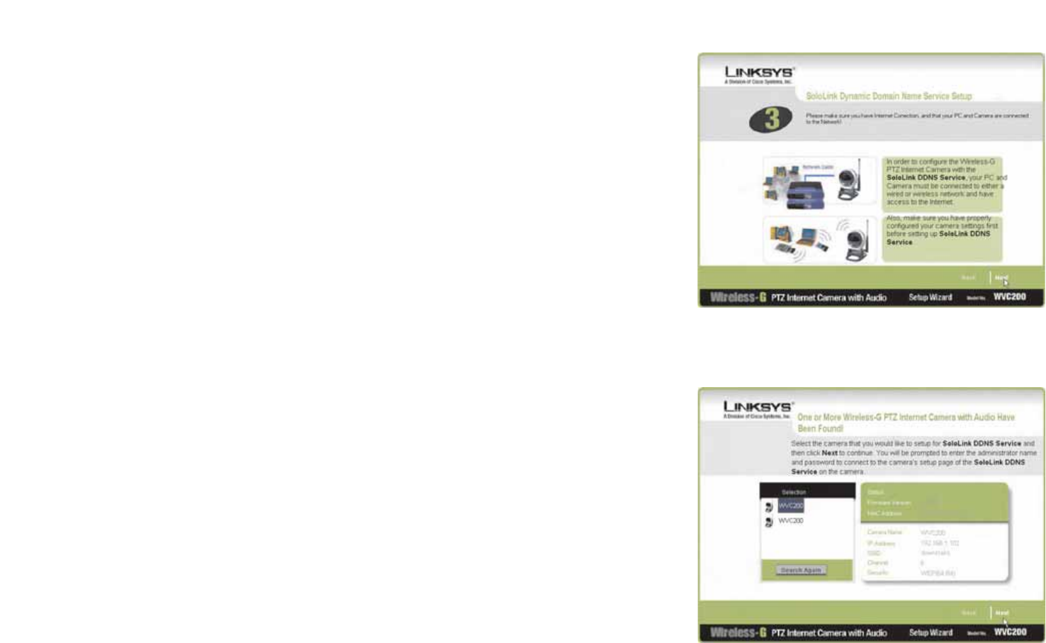
4. Make sure your network has an active Internet connection. Verify that your PC and Camera are connected to
the network and the Camera is configured properly. Click Next.
5. A list of Wireless-G Internet Cameras on your network and their status information is displayed next. In the
Selection box, click the name of the Camera you are currently setting up. Then, click the Next button.
Figure 6-4: Check Connections Screen
Figure 6-5: Cameras Found Screen
33
Chapter 6: Setting up the Linksys SoloLinktm DDNS Service
Setup Wizard for the SoloLink DDNS Service
Wireless-G PTZ Internet Camera with Audio
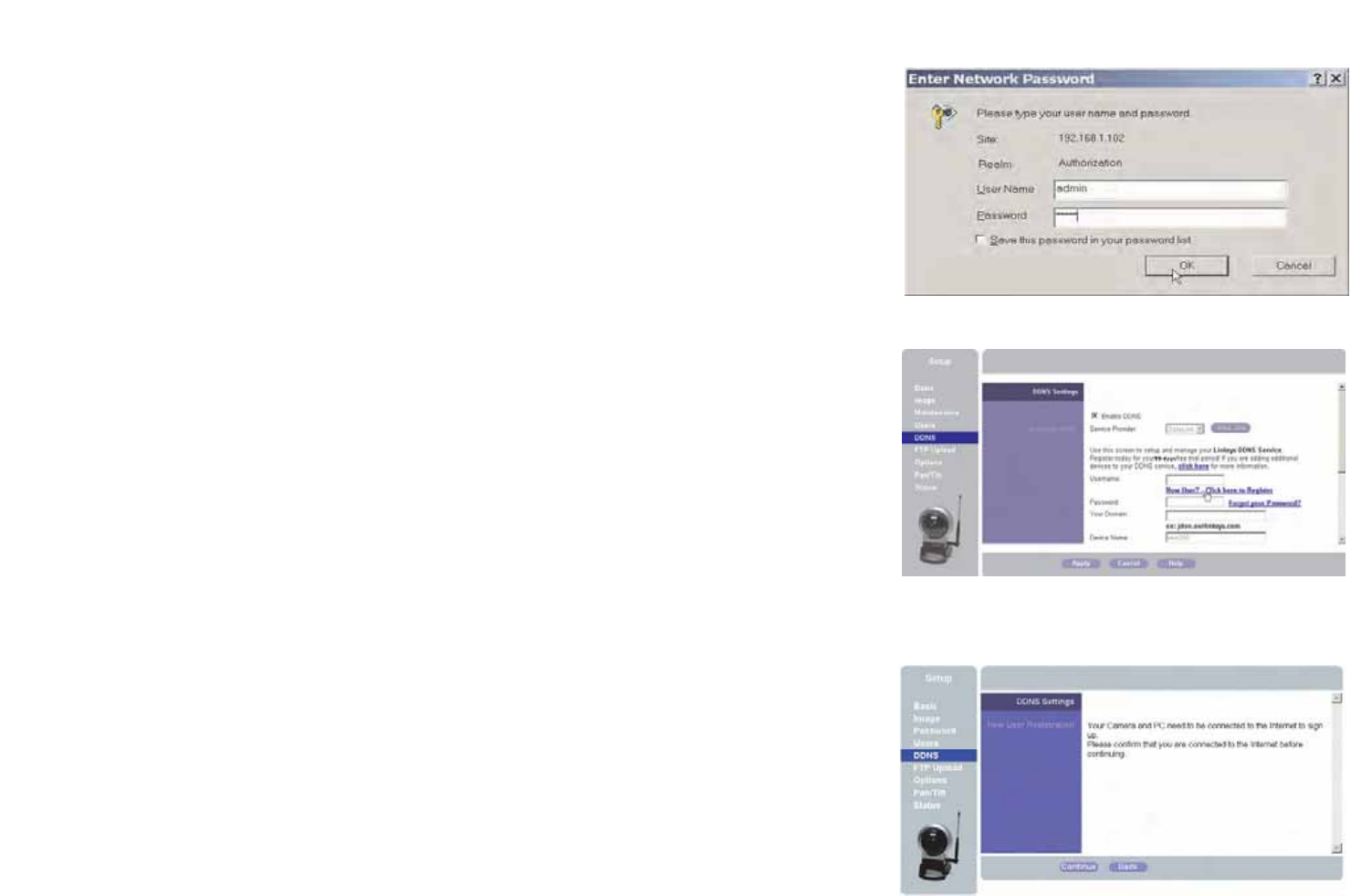
6. To ensure security, you will be asked to enter a user name and password before you can access the Camera.
If you have not changed the Camera’s user name and password, then enter admin in the User name and
Password fields (admin is the default). Then, click the OK button.
7. Your web browser will automatically start up, and the SoloLink DDNS screen of the Camera’s Web-based
Utility will appear. Click the Enable DDNS checkbox, then click New User ? - Click here to Register.
8. Verify that your network has an active Internet connection and click Continue.
Figure 6-6: Login Screen
Figure 6-7: SoloLink DDNS Screen
Figure 6-8: Confirm Active Internet Connection Screen

34
Chapter 6: Setting up the Linksys SoloLinktm DDNS Service
Setup Wizard for the SoloLink DDNS Service
Wireless-G PTZ Internet Camera with Audio
9. On the Welcome to the SoloLink DDNS Service screen, click Set up a NEW Account.
10. On the Sign Up screen, enter the Access ID for your free trial offer. It is provided on the Promotion Card
included with the Camera. (If you don’t have an Access ID, then leave the Access ID field blank.)
Then enter your account and user information. Enter a Username and Password for your account. Enter the
Password again in the Confirm Password field.
Complete the following required fields: First Name, Last Name, Phone, and Email. You can also enter your
postal address and choose to receive updates by e-mail. Then, click Continue.
Figure 6-9: Welcome to the SoloLink DDNS Service Screen
Figure 6-10: Sign Up Screen
35
Chapter 6: Setting up the Linksys SoloLinktm DDNS Service
Setup Wizard for the SoloLink DDNS Service
Wireless-G PTZ Internet Camera with Audio
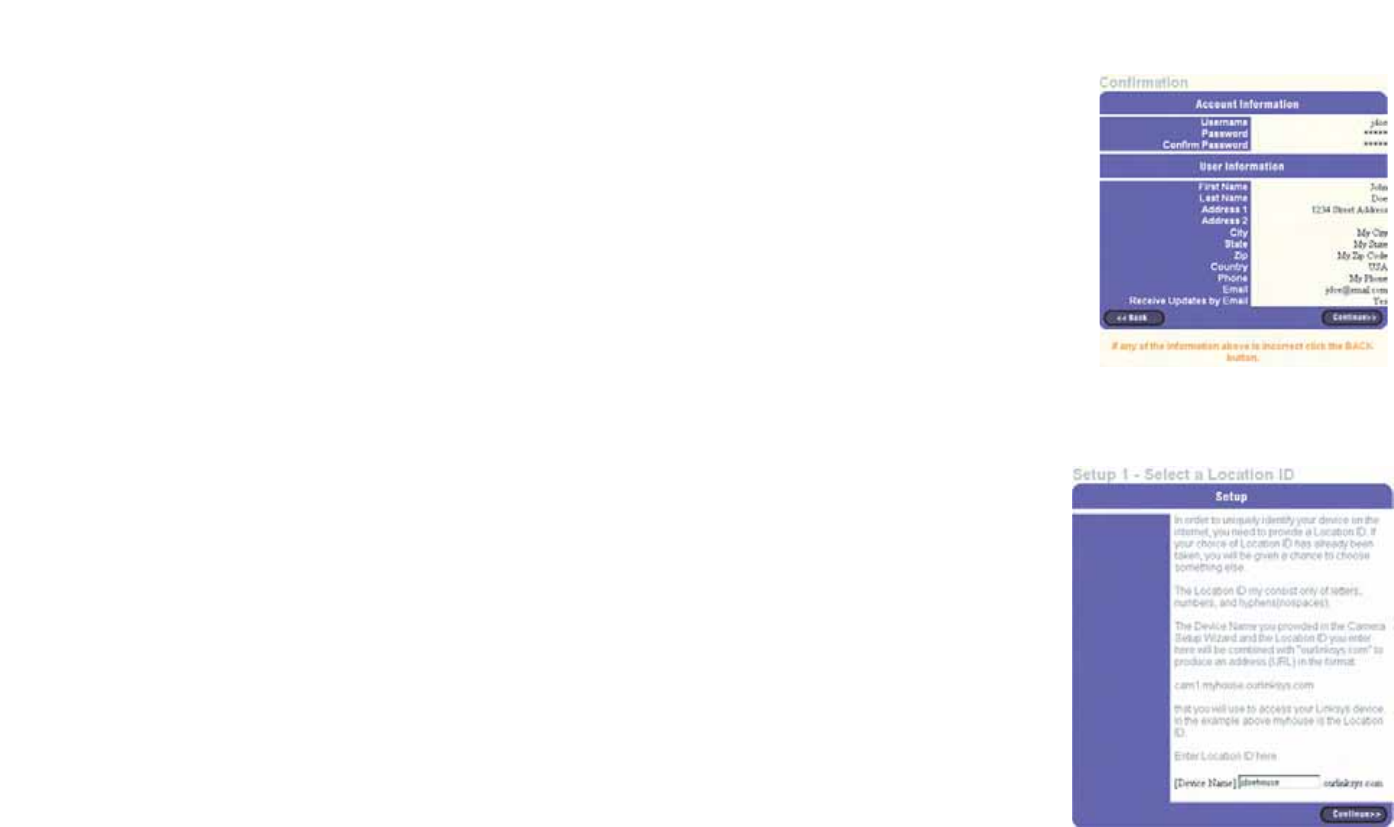
11. Review your information on the Confirmation screen. If the new settings are correct, click Continue.
12. On the Select a Location ID screen, enter a Location ID, which can be a name describing your network’s
location. It will be combined with the Camera’s Device Name and ourlinksys.com to create a convenient URL
you can use to access the Camera. Click Continue.
Figure 6-12: Select a Location ID Screen
Figure 6-11: Confirmation of New Settings Screen
36
Chapter 6: Setting up the Linksys SoloLinktm DDNS Service
Setup Wizard for the SoloLink DDNS Service
Wireless-G PTZ Internet Camera with Audio
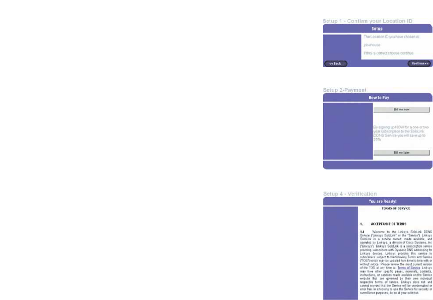
13. On the Confirm your Location ID screen, verify that the Location ID is correct. Then, click Continue.
14. On the Payment screen, choose one of two payment plans, Bill me now or Bill me later. (If you did not enter
an Access ID, then you have one choice, Bill me now.)
If you click Bill me later, go to step 15.
If you click Bill me now, you will see a screen asking for billing information. Follow the on-screen instructions
and then go to step 15.
15. Read the Terms of Service agreement on the Verification screen. Click Create Account to accept the terms of
service.
Figure 6-14: Payment Screen
Figure 6-13: Confirm Your Location ID Screen
Figure 6-15: Verification Screen
37
Chapter 6: Setting up the Linksys SoloLinktm DDNS Service
Setup Wizard for the SoloLink DDNS Service
Wireless-G PTZ Internet Camera with Audio
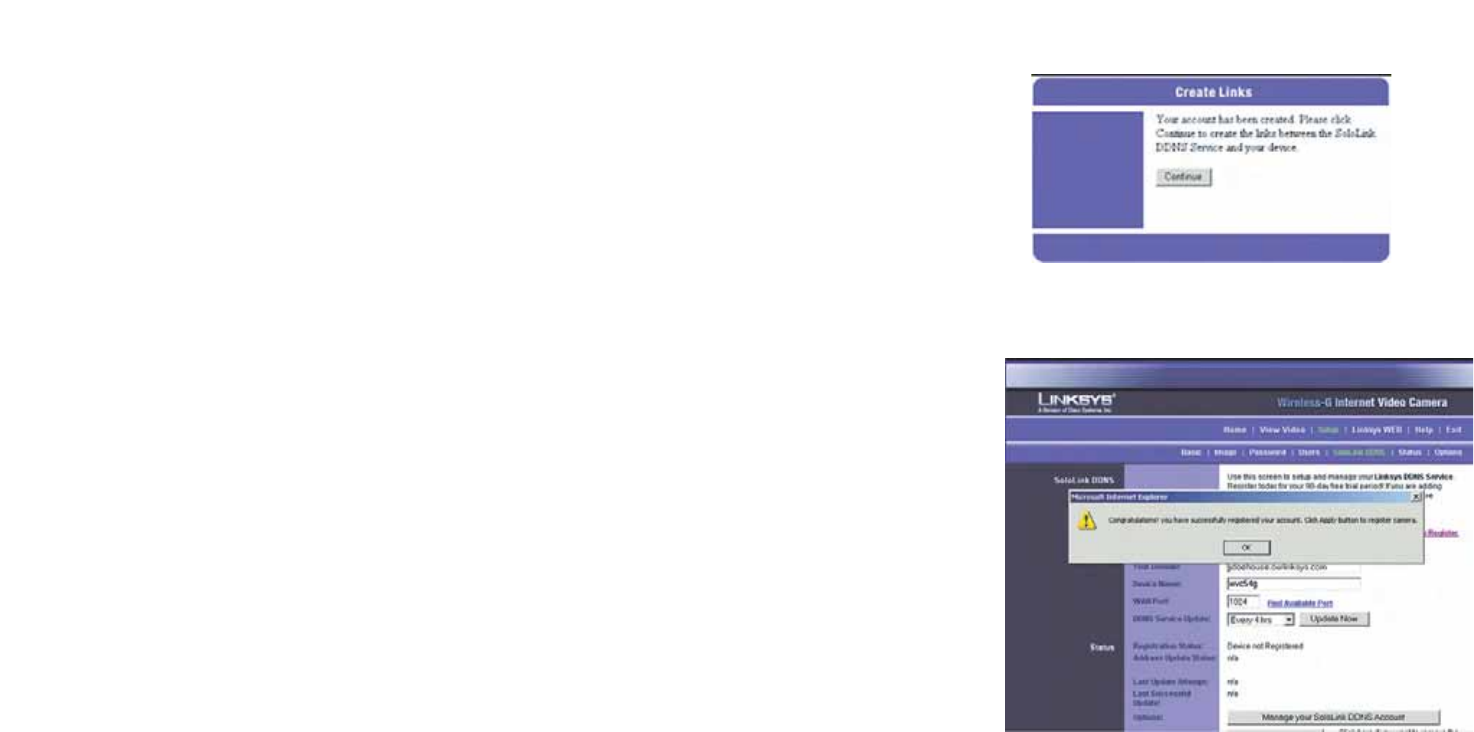
16. On the Create Links screen, click Continue. The SoloLink DDNS Service will send your account information to
the Camera.
17. A pop-up screen will inform you that you have successfully registered your account. Click OK.
At the bottom of the SoloLink DDNS screen, click the Apply button to register the Camera with your account.
Figure 6-16: Create Links Screen
Figure 6-17: Successful Registration Screen
38
Chapter 6: Setting up the Linksys SoloLinktm DDNS Service
Setup Wizard for the SoloLink DDNS Service
Wireless-G PTZ Internet Camera with Audio
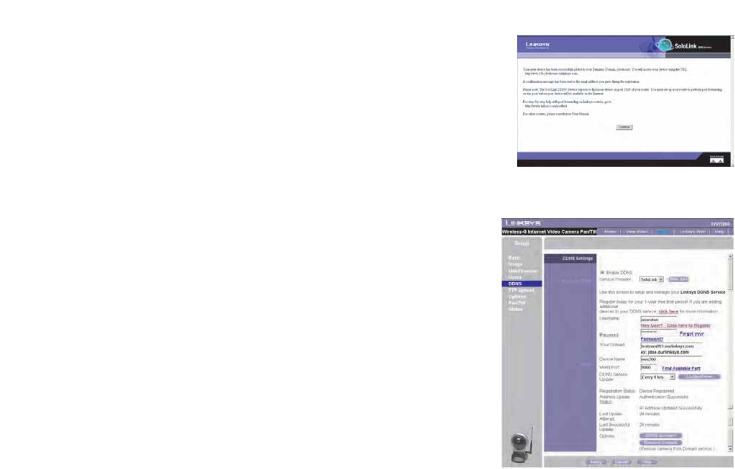
18. A confirmation page will display the link or address you will use to access the Camera and the port number
the SoloLink DDNS Service will use to find the Camera. Click Continue.
19. A pop-up screen will inform you that you have successfully set up the SoloLink DDNS Service for the Camera.
Click OK.
Figure 6-18: Account Confirmation of Camera Screen
Figure 6-19: Successful Setup Screen
39
Chapter 6: Setting up the Linksys SoloLinktm DDNS Service
SoloLink Registration of Additional Cameras
Wireless-G PTZ Internet Camera with Audio
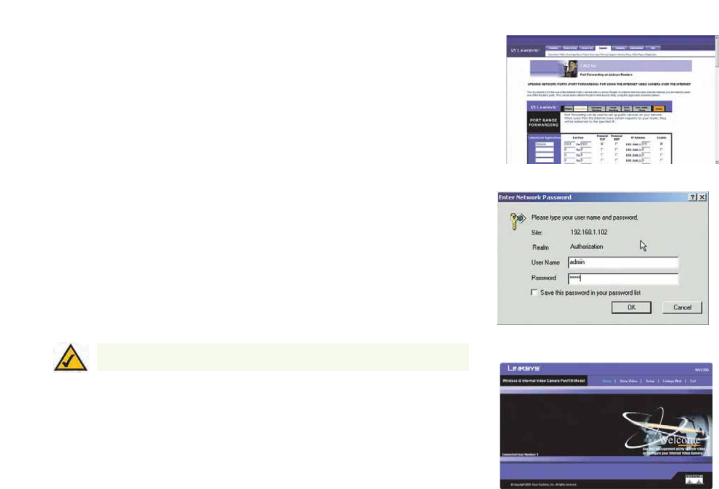
20. Set up port forwarding on your network router, so the SoloLink DDNS Service will be able to track the
Wireless-G Internet Camera. Go to www.linksys.com/portfwd for instructions on how to configure a Linksys
router.
For other routers, refer to your router’s documentation.
The SoloLink DDNS setup is complete. If you want to register more Cameras with your SoloLink account,
proceed to the “SoloLink Registration of Additional Cameras” section.
For more information about the Camera’s Web-based Utility, proceed to “Chapter 8: Using the
Wireless-G Internet Camera Web-based Utility.”
SoloLink Registration of Additional Cameras
After you have set up your SoloLink account, you can add more Cameras to your SoloLink account using each
Camera’s Web-based Utility. Follow these instructions for each Camera you add:
1. To access a Camera’s Web-based Utility, launch Internet Explorer, enter the Camera’s IP address in the
Address field, then press Enter.
2. A login screen will appear. (Windows XP users will see a similar screen.) Enter admin (the default user name
and password) in the User Name and Password fields. Then click the OK button.
3. The Welcome screen will appear. Click the Setup tab.
4. Click the SoloLink DDNS tab.
NOTE: Make sure you set up the port forwarding feature on your network router, so the SoloLink
DDNS Service will be able to access the Camera.
Figure 6-20: Port Forwarding Information
Figure 6-21: Web Utility Login Screen
Figure 6-22: Web-based Utility Welcome
40
Chapter 6: Setting up the Linksys SoloLinktm DDNS Service
SoloLink Registration of Additional Cameras
Wireless-G PTZ Internet Camera with Audio
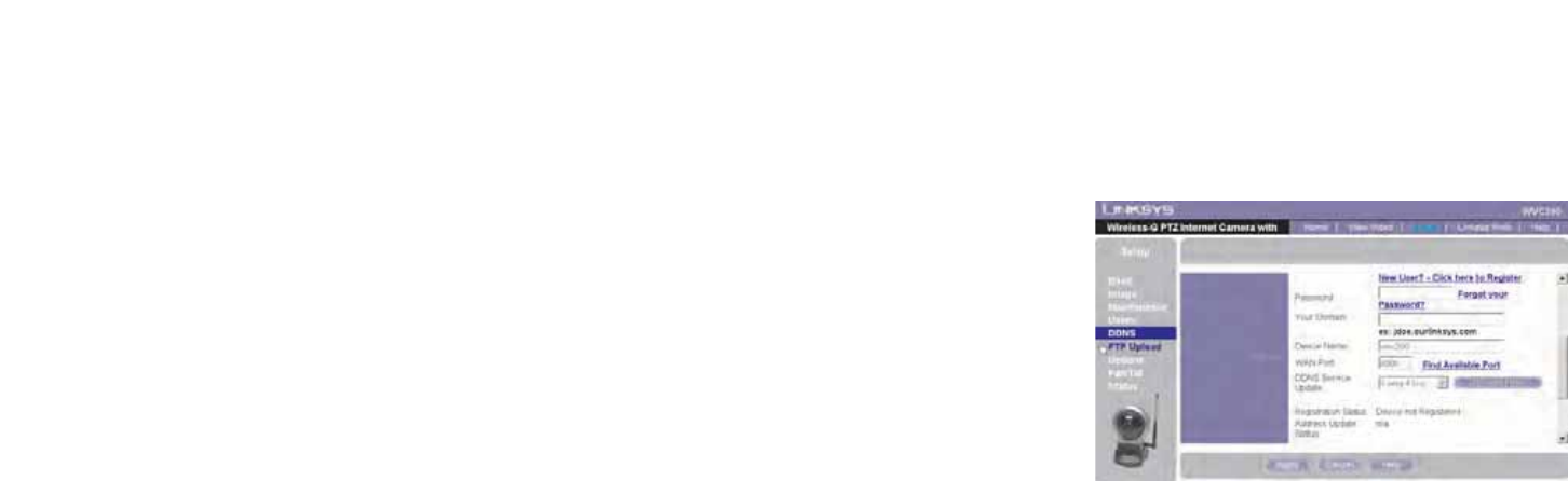
5. In the Username, Password, and Your Domain fields, enter your SoloLink account information.
6. In the Device Name field, give the Camera a unique name. The DDNS service will not work if multiple Cameras
have the same Device Name.
7. In the WAN Port field, enter a unique port number. This is the number of the port you will use to access the
Camera remotely. If you need to find an available port, click Find Available Port and follow the on-screen
instructions. The DDNS service will not work if multiple Cameras use the same WAN port.
8. Depending on how often you want the DDNS service to update the dynamic IP address, select the appropriate
time interval from the DDNS Service Update drop-down menu. To update the dynamic IP address immediately,
click the Update Now button.
9. Click the Apply button on the SoloLink DDNS screen. The Camera will automatically register itself with your
SoloLink account.
10. Set up port forwarding on your network router, so the SoloLink DDNS Service will be able to track the
Wireless-G Internet Camera. Go to www.linksys.com/portfwd for instructions on how to configure a Linksys
router.
For other routers, refer to your router’s documentation.
The Camera has been added to your SoloLink account.
For more information about the Camera’s Web-based Utility, proceed to “Chapter 7: Using the
Wireless-G Internet Camera Web-based Utility.”
Figure 6-23: Find Available Port Screen

41
Chapter 7: Using the Wireless-G Internet Camera’s Web-based Utility
Overview
Wireless-G PTZ Internet Camera with Audio
Chapter 7: Using the Wireless-G Internet Camera’s
Web-based Utility
Overview
Use the Camera’s Web-based Utility to access and alter its settings. This chapter will describe each webpage in
the Utility and its features. The Utility can be accessed via the web browser of a computer connected to the
Camera.
How to Access the Web-based Utility
To access the Utility, launch Internet Explorer, and enter the Camera’s IP address in the Address field. (If there are
no DHCP servers available, the camera automatically default to 192.168.1.115.) Then press Enter.
To ensure security, you will be asked to enter a user name and password before you can access the Camera. If
you have not changed the Camera’s user name and password, then enter admin in the User name and Password
fields (admin is the default). Then, click the OK button.
The Welcome screen of the Web-based Utility will appear.
You have six tabs available:
•Home. To return to the Welcome screen, click the Home tab.
•View Video. To view the Camera’s video, click the View Video tab. Go to the “View Video” section for more
information.
•Setup. To alter the Camera’s settings, click the Setup tab. Go to the “Setup” section for more information.
•Linksys WEB. To go to the Linksys website, www.linksys.com, click the Linksys WEB tab.
•Help. The Help screen allows you to get information about the various Setup screens, download the latest
Viewer & Recording Utility, download this User Guide, download Acrobat Reader, restore factory defaults, and
upgrade the Camera’s firmware. Go to the “Help” section for more information.
•Exit. To close the Utility, click the Exit tab.
Figure 7-2: Web-based Utility Welcome
Figure 7-1: Camera’s Default IP Address
42
Chapter 7: Using the Wireless-G Internet Camera’s Web-based Utility
View Video
Wireless-G PTZ Internet Camera with Audio
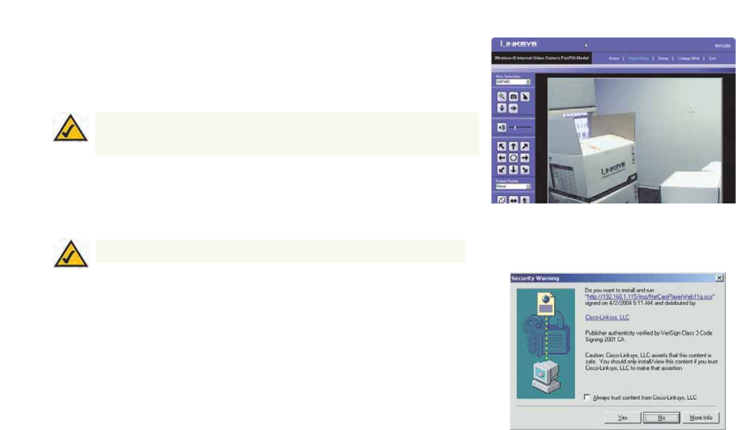
View Video
Follow these instructions to view the Camera’s video.
1. Click the View Video tab on the Welcome screen.
2. A Security Warning screen about an OCX plug-in may appear. To enable your computer to see the Camera’s
video, click the Yes button.
3. A screen will appear showing you the video from the Camera.
NOTE: For added security, you should always change the Login Name and Password through the
Utility’s Users screen.
Figure 7-4: Security Warning Screen
NOTE: To view video using a web browser, you must use Internet Explorer version 5.5 or higher. The
View Video feature will not work with Netscape. Netscape users should use the Viewer & Recorder
Utility instead.
Figure 7-3: View Video Screen

43
Chapter 7: Using the Wireless-G Internet Camera’s Web-based Utility
Setup
Wireless-G PTZ Internet Camera with Audio
Setup
The Basic screen will appear. You have six tabs available:
•Basic. To configure the Camera’s basic, LAN, and wireless settings, use the Basic screen.
•Image. Customize the video settings on the Image screen.
•Maintenance. Reset the Camera’s factory defaults and upgrade the Camera’s firmware from this tab.
•Users. Designate user’s level of access and manage passwords for the Camera on this screen.
•DDNS. DDNS (Dynamic Domain Name System) lets you assign a fixed host and domain name to a dynamic
Internet IP address.
•FTP Upload. Manage the uploading of images to an FTP site from this tab.
•Options. The e-mail alert options, Universal Plug and Play (UPnP) setting, and Alternate Port settings are
configured on the Options screen.
•Pan/Tilt. Set and calibrate the Camera’s pan and tilt options from this screen.
•Status. Status information and a log are displayed on this screen.
To save your changes, click the Apply button. To cancel any unsaved changes, click the Cancel button. To get
additional information about a screen’s features, click the Help button.
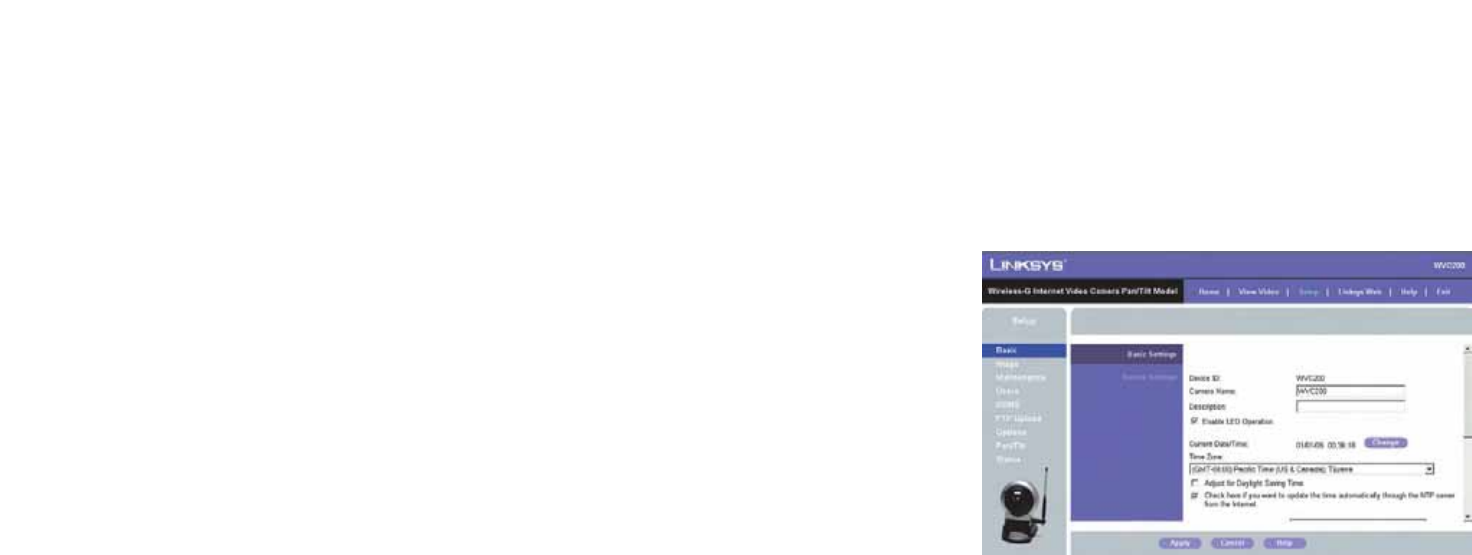
Basic
The Basic screen allows you to alter the Camera’s settings, including the network and wireless configuration.
Device Settings
Device ID. Displayed here is the Camera’s identification name, which is used by the Camera and the Utility to
exchange data.
Camera Name. You may assign any name to the Camera. Unique, memorable names are helpful, especially if you
are using multiple Cameras on the same wireless network. You can enter up to 15 characters.
Description. Enter information about the Camera in this field. You can enter up to 32 characters.
LED Operation. This feature allows you enable or disable the Camera’s LEDs.
Figure 7-5: Basic Screen

44
Chapter 7: Using the Wireless-G Internet Camera’s Web-based Utility
Setup
Wireless-G PTZ Internet Camera with Audio
Date. Enter the current date.
Time. Enter the current time.
Time Zone. Select the time zone for the Camera’s location.
Network Time Protocol. If you want to update the Camera’s time through an NTP (Network Time Protocol) server
on the Internet, click the first checkbox. When the NTP feature is enabled, the daylight savings option will be
available. If you want to adjust the Camera’s current time for daylight savings, click the second checkbox.
LAN Settings
Configuration Type. If the Bridge will obtain an IP address automatically from a DHCP server, then select
Automatic Configuration - DHCP. If you will assign the Camera a static IP address, then select Static IP
Address, and complete the IP Address, Subnet Mask, Gateway, and DNS fields.
IP Address, Subnet Mask, Gateway, Primary DNS, Secondary DNS. Complete these fields if the Camera will
use a static IP address. You need to enter at least one DNS address.
Wireless Settings
SSID. Enter the network’s SSID or network name here.
Network Type. Select the network’s mode, Infrastructure or Ad-hoc.
Channel No. If the Camera is set to ad-hoc mode, select its channel setting from the drop-down menu.
Security. To use WEP encryption, click the Enable radio button. You will be asked to confirm that you want to
enable wireless security for the Camera. Click the OK button. Then click the Edit Security Settings button. For
more information, go to the “Security Settings” section. To disable WEP encryption, click the Disable radio
button.
To save your changes, click the Apply button. To cancel any unsaved changes, click the Cancel button. To get
additional information about the screen’s features, click the Help button.
Security Settings
Configure the Camera’s WEP encryption settings on this screen. Make sure all devices on your wireless network
use the same settings.
Default Transmit Key. Select which WEP key (1-4) will be used when your network’s access point or wireless
router sends and receives data.
Figure 7-6: Confirmation Screen
45
Chapter 7: Using the Wireless-G Internet Camera’s Web-based Utility
Setup
Wireless-G PTZ Internet Camera with Audio
WEP Encryption. Select the level of WEP encryption you wish to use, 64 Bit Keys (10 Hex chars) or 128 Bit
Keys (26 Hex chars).
Passphrase. Instead of manually entering WEP keys, you can use a Passphrase to generate them. It is case-
sensitive and should not be longer than 16 alphanumeric characters. (This Passphrase is compatible with Linksys
wireless products only. If you are also using non-Linksys wireless products, you will need to enter your WEP keys
manually on those products.) After entering the Passphrase, click the Generate button to create WEP key(s).
Key 1-4. If you are used a Passphrase, the WEP keys will be displayed after you have generated them. If you are
not using a Passphrase, manually enter a set of values in each field. (For 128-bit WEP, only one WEP key is
permitted.) If you are using 64-bit WEP encryption, then each key must consist of exactly 10 hexadecimal
characters. If you are using 128-bit WEP encryption, then the key must consist of exactly 26 hexadecimal
characters. Valid hexadecimal characters are “0” through “9” and “A” through “F”.
WPA-Personal. To enable WPA-Personal encryption, enter a WPA Shared Key from 8 to 63 characters.
WPA Shared Key. If you enabled WPA-Personal encryption, enter the WPA Shared Key that you’re using on your
wireless network.
Authentication. The default is set to Open System, for which the sender and the recipient do NOT use a WEP
key for authentication. You can also choose Shared Key, when the sender and recipient use a WEP key for
authentication. This setting should match the one on your network’s access point or wireless router.
To save your changes, click the Apply button. To cancel your changes, click the Cancel button. To get additional
information about the screen’s features, click the Help button.
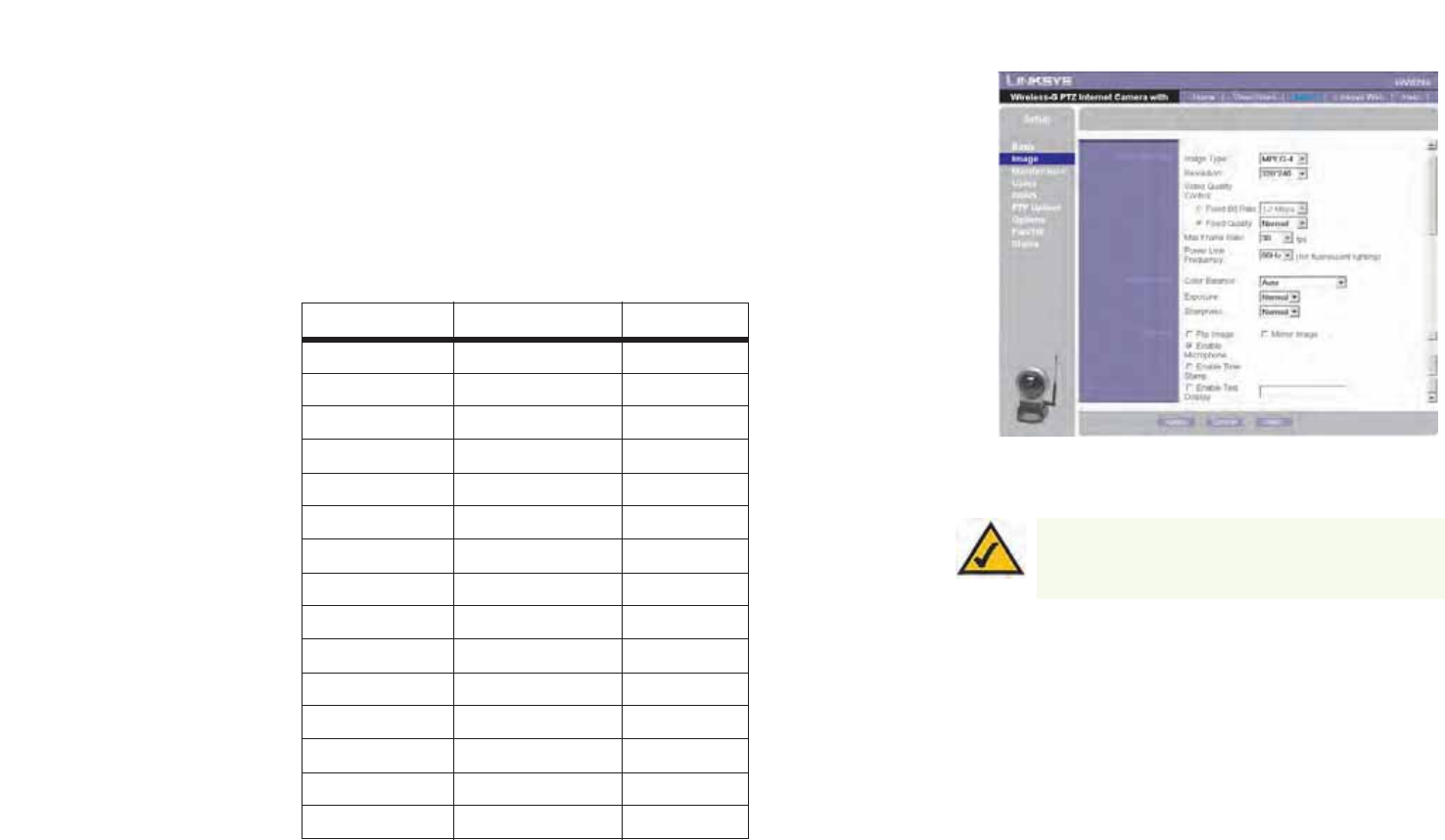
Image
The Image screen allows you to alter the Camera’s video settings.
Video Settings
Image Type. Select the desired type:
• MPEG-4 gives smooth motion and high quality images, but the video image quality will deteriorate if
sufficient bandwidth is not available.
• MJPEG requires more bandwidth than MPEG-4, but if the bandwidth is insufficient, the frame rate will
drop, and the image quality will remain at the same level.
Resolution. Select the resolution you want for viewing or recording the Camera’s video. Select 640 * 480 for the
highest resolution, 320*240 for medium resolution, and select 160*120 for the lowest resolution.
Figure 7-7: WEP Key Settings Screen
46
Chapter 7: Using the Wireless-G Internet Camera’s Web-based Utility
Setup
Wireless-G PTZ Internet Camera with Audio
Fix Quality. Select the level of quality you want for viewing or recording the Camera’s video. The range varies
from Very Low to Very High.
Fix Bit Rate. Select the level of quality you want for viewing or recording the Camera’s video. The range varies
from 64 kbps to 2 Mbps.
You may find it helpful to know what the bit rates are for video viewing or recording at different resolutions and
image quality levels. The following table lists these estimated bit rates.
Estimated Bit Rates for Video Viewing or Recording
Resolution Quality Level Bit Rate
640 x 480 Very High 4000kbps
640 x 480 High 3200kbps
640 x 480 Normal 1200kbps
640 x 480 Low 480kbps
640 x 480 Very Low 160kbps
320 x 240 Very High 1000kbps
320 x 240 High 800kbps
320 x 240 Normal 300kbps
320 x 240 Low 120kbps
320 x 240 Very Low 40kbps
160 x 120 Very High 800kbps
160 x 120 High 400kbps
160 x 120 Normal 200kbps
160 x 120 Low 100kbps
160 x 120 Very Low 40kbps
Figure 7-8: Image Screen
NOTE: Video quality and/or performance may be
affected by the number of users connected to the
Camera.

47
Chapter 7: Using the Wireless-G Internet Camera’s Web-based Utility
Setup
Wireless-G PTZ Internet Camera with Audio
Video Quality Control. Select the desired Maximum bandwidth for the video stream. Note that you can specify
EITHER the Bandwidth OR the Frame Rate, not both. If Bandwidth is defined, the frame rate will be adjusted as
necessary to achieve the best possible frame rate at that bandwidth that the network can carry.
The default values for the bandwidth is Unlimited, which allows you to specify the desired frame rate.
Max Frame Rate. Select the maximum frame rate for the camera. Reducing this will lower the amount of
bandwidth required by the camera.
Power Line Frequency. Select the power line frequency (50Hz or 60Hz) used in your region, to improve the
picture quality under florescent lighting.
Adjustments
Color Balance. Select the desired option to match the current environment and lighting.
Exposure. If necessary, you can adjust the exposure to obtain a better image. For example, if the camera is facing
minimal light, the image may be too dark. In this case, you can increase the exposure.
Sharpness. Select the desired option for the sharpness. You can select a Sharpness value between -3 and 3.
Options
Flip Image/Mirror Image. The Flip setting will rotate the image 180° vertically; the Mirror setting will rotate the
image 180° horizontally. If the camera is mounted upside-down on the ceiling, check both the Flip and Mirror
settings to have the image rotated to the correct position.
Enable Microphone. Enable audio by checking this checkbox. Using Audio will increase the bandwidth
requirements slightly.
Time Stamp. If you want a time stamp shown on the video, click the checkbox next to Enable.
Text Display. If you want text shown on the video, click the checkbox next to Enable. Then complete the Text field
with up to 20 characters.
To save your changes, click the Apply button. To cancel any unsaved changes, click the Cancel button. To get
additional information about the screen’s features, click the Help button.
48
Chapter 7: Using the Wireless-G Internet Camera’s Web-based Utility
Setup
Wireless-G PTZ Internet Camera with Audio
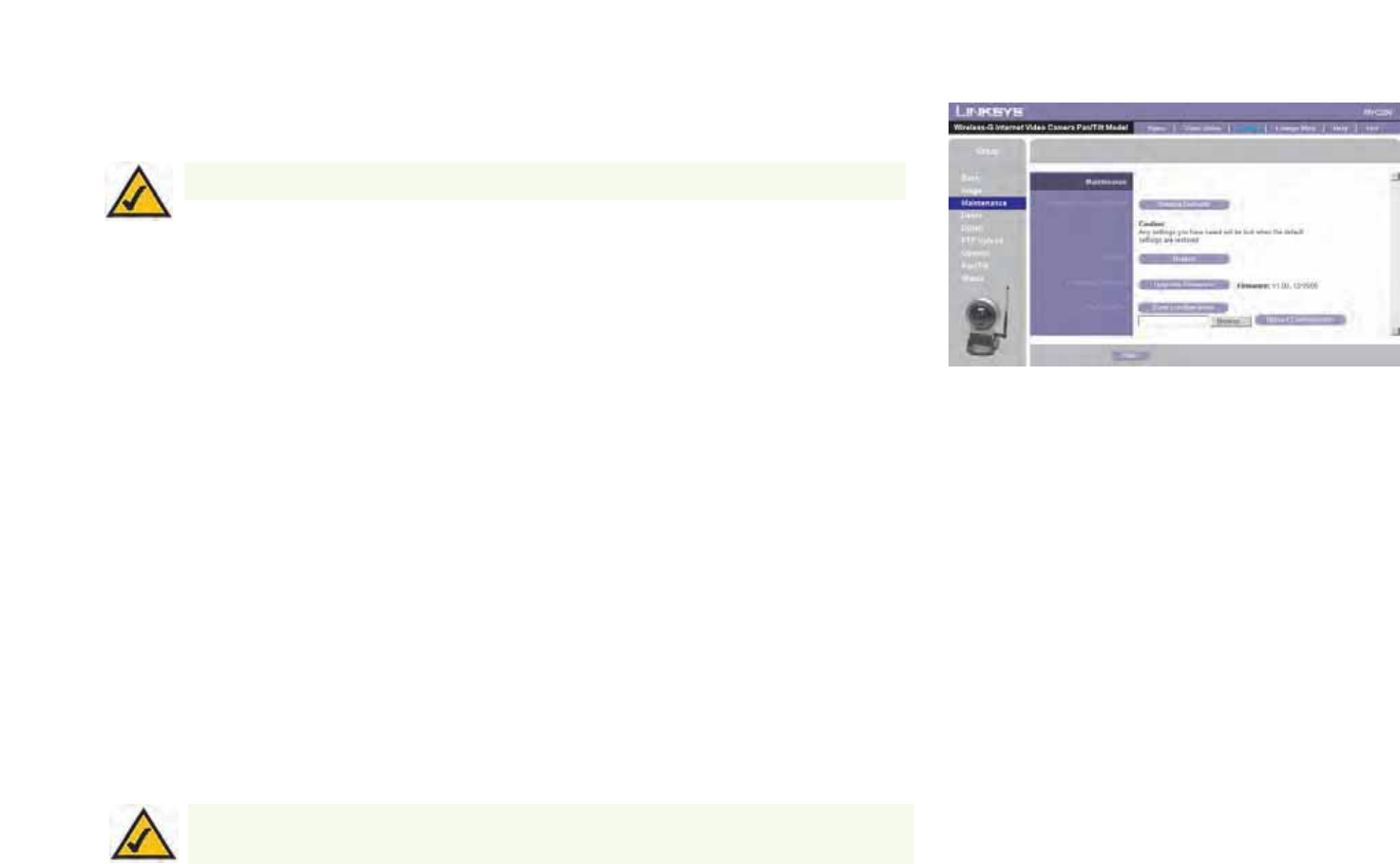
Maintenance
The Maintenance screen allows you to reset the Camera’s factory defaults and upgrade the firmware.
Restore Factory Defaults. To restore the Camera’s factory default settings, click the Restore Defaults button.
Firmware. New firmware versions are posted at www.linksys.com and can be downloaded for free. If the Camera
is functioning well, there is no need to download a newer firmware version, unless that version has a new feature
that you want to use. Loading new firmware onto the Camera does not always enhance its performance.
Linksys recommends that you upgrade the Camera’s firmware within your network; in other words, use a
computer within the Camera’s local network. If you attempt to upgrade the Camera’s firmware from a remote
location—using a computer outside of the Camera’s local network—the upgrade will fail.
To upgrade the firmware:
1. Go to the Linksys website, www.linksys.com, and download the firmware upgrade file for the Camera. Then
extract the file.
2. From the Help screen, click the Firmware Upgrade button.
3. You will see the Upgrade Firmware screen. Click the Browse button to find the extracted file, and then
double-click it.
4. Click the Start Upgrade button, and follow the on-screen instructions. To cancel the upgrade, click the
Cancel button. For further help, click the Help button.
Figure 7-9: Maintenance Screen
NOTE: When you restore the Camera’s factory defaults, you will lose the settings you have
saved previously.
NOTE: When you upgrade the Camera’s firmware, you may lose the settings you have
saved previously.
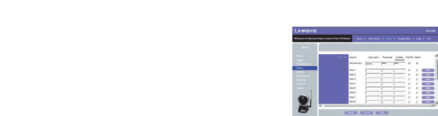
49
Chapter 7: Using the Wireless-G Internet Camera’s Web-based Utility
Setup
Wireless-G PTZ Internet Camera with Audio
Users
The Users screen allows you to designate access rights for Camera users.
User Name. Complete this field with a name of your choice.
Password and Verify Password. Enter your new password in both fields. The password should have eight
characters or fewer.
Pan/Tilt. This box sets a user’s access to the Pan/Tilt options. Click this box to set access.
Setup. Allows users to configure the camera without having to give them administrator rights.
Click the Add button to set the user’s information.
To save your changes, click the Apply button. To cancel any unsaved changes, click the Cancel button. To get
additional information about the screen’s features, click the Help button. Figure 7-10: Users Screen
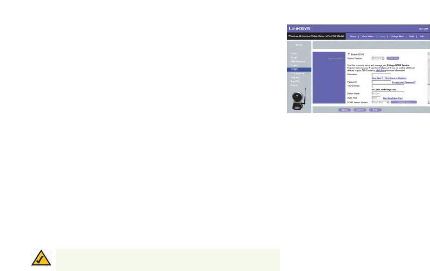
50
Chapter 7: Using the Wireless-G Internet Camera’s Web-based Utility
Setup
Wireless-G PTZ Internet Camera with Audio
DDNS
The DDNS screen allows you to set up and configure your DDNS Service. DDNS (Dynamic Domain Name System)
lets you assign a fixed host and domain name to a dynamic Internet IP address. If you have already set up your
SoloLink account, then you can use this screen to register additional Cameras.
Enable DDNS. Click this box to enable a DDNS service with the Camera.
Service Provider. Select your DDNS service provider from this drop-down menu.
Username. Enter the username you have set up on your SoloLink account. If you are a new user, click New
User? - Click here to Register. The New User Registration screen will appear. Click the Continue button, or
click the Back screen to return to the previous screen. Your web browser will automatically start up, and you will
visit a website to set up your SoloLink account. Follow the on-screen instructions. For more information, refer to
“Chapter 7: Setting up the Linksys SoloLink DDNS Service,” which will guide you through setup of your SoloLink
account.
Password. Enter the password you have set up on your SoloLink account. If you have forgotten your password,
click Forgot your Password?
The Password Request screen will appear. Complete the Domain name field. Click the Request Password button
to request your username and password, which will be e-mailed to the e-mail address registered with your
SoloLink DDNS account. Click the Cancel button to cancel your change. Click the Back button to return to the
previous screen.
Your Domain. Enter the host and domain name you have set up on your SoloLink account. It should be in this
format: <Location ID>.ourlinksys.com. For example, if myhouse is the Location ID, then the host and domain
name would be myhouse.ourlinksys.com.
Device Name. Enter the name you have given the Camera.
WAN Port. Enter the number of the port you will use to remotely access the Camera. If you need to find an
available port, click Find Available Port and follow the on-screen instructions.
DDNS Service Update. Depending on how often you want the DDNS service to update the dynamic IP address,
select the appropriate time interval from the drop-down menu. To update the dynamic IP address immediately,
click the Update Now button.
NOTE: If you use the Camera’s DDNS feature, then you must also configure the port forwarding
feature on your network router. Go to www.linksys.com/portfwd for instructions on how to configure
a Linksys router. For other routers, refer to your router’s documentation.
Figure 7-11: DDNS Screen
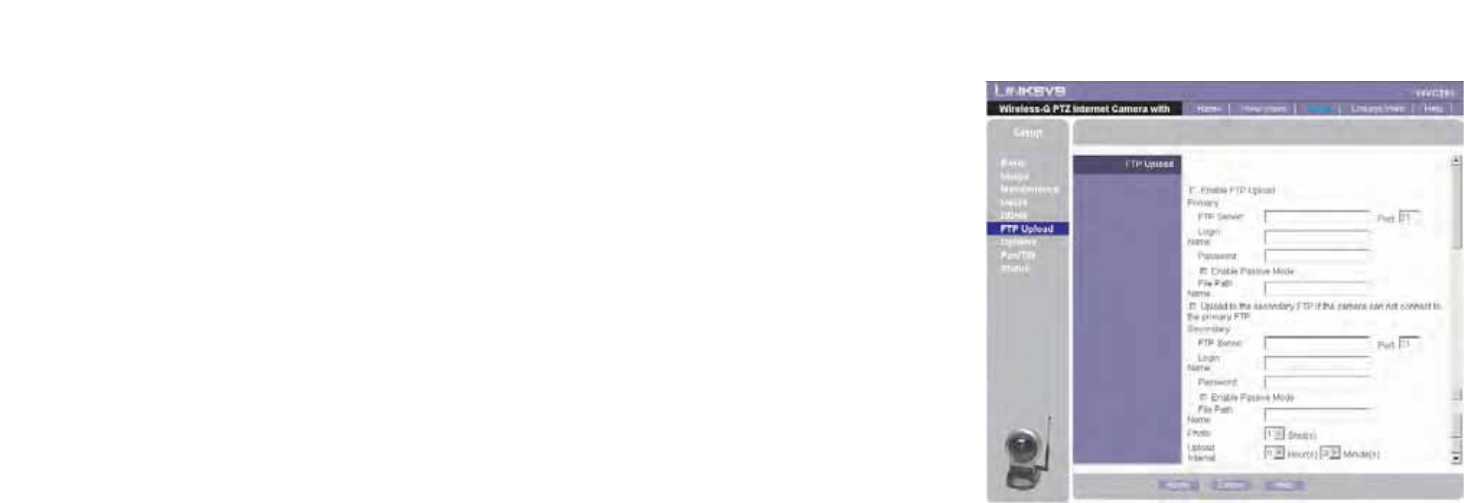
51
Chapter 7: Using the Wireless-G Internet Camera’s Web-based Utility
Setup
Wireless-G PTZ Internet Camera with Audio
FTP Upload
The FTP Upload screen allows you to manage images uploaded to an FTP server.
Enable FTP Upload. Check this box to enable the FTP Upload feature. If enabled, you must enter details of the
FTP Server.
Primary FTP Server. Enter the name or IP address of the Primary FTP Server.
Secondary FTP Server. Enter the name or IP address of the Secondary FTP Server. If the Camera is unable to
connect to the Primary FTP Server, it will try to connect to the Secondary FTP Server. The Camera can connect to
only one server at a time and will only connect to the Secondary FTP Server when it is unable to connect to the
Primary FTP Server.
Login Name. Enter the Login name required to gain access to the FTP server.
Password. Enter the password required to gain access to the FTP server.
Photo. Enter the desired photo shot here. Up to four snapshots can be uploaded per interval.
Enable Passive Mode. Use the checkbox to enable the Passive Mode feature as required.
File Pathname. Enter the desired pathname here.
Upload Interval. Select the desired option for the upload interval.
To save your changes, click the Apply button. To cancel any unsaved changes, click the Cancel button. To get
additional information about the screen’s features, click the Help button.
Figure 7-12: FTP Upload Screen
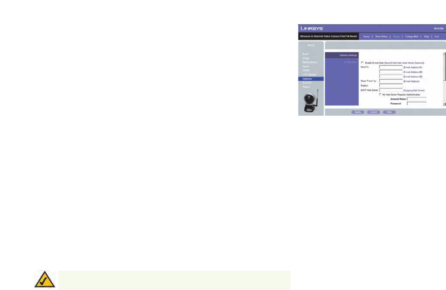
52
Chapter 7: Using the Wireless-G Internet Camera’s Web-based Utility
Setup
Wireless-G PTZ Internet Camera with Audio
Options
The Options screen allows you to alter the Camera’s e-mail alert features, UPnP configuration, and Alternate Port
settings.
E-mail Alert
You can choose to be notified when the Camera detects motion in its field of view. You will be sent a text-only e-
mail or an e-mail with video attached.
E-mail Alert. If you want to be notified by e-mail when the Camera detects motion, then select Enable from the
drop-down menu. Otherwise, select Disable.
Send to. In each field, enter an e-mail address that will receive e-mail alerts. (You can enter up to three e-mail
addresses.)
Show “From” as. Enter the text that you want displayed in the From field of any e-mail alert message.
Subject. Enter the subject heading that you want to be used.
SMTP Mail Server. Enter the IP address of the outgoing mail SMTP server. If it requires authentication, click the
checkbox, and enter the account name and password in the Account Name and Password fields.
Pan/Tilt. This option is only available if your camera is fitted with a Pan/Tilt control. If available, select the desired
option to resolve conflict between the Pan/Tilt and Motion Detection features.
Delay between E-mails. Specify the minimum time interval between e-mail alerts. The default is 2 minutes.
E-Mail Video. If you want e-mail sent with a video attachment, select Enable from the drop-down menu. Then
select the length of video you want, up to a maximum of 5 seconds. The default is 2 seconds. If you want text-
only e-mail sent to you, select Disable from the drop-down menu.
Area/Sensitivity. Click this button to enter the motion detection sub-screen. You can set the area or areas of the
video image to be examined, and adjust the sensitivity of detection for each area.
Figure 7-13: Options Screen
NOTE: Motion detection can be triggered by rapid changes in lighting condition, as well as by
moving objects. For this reason, it should only be used indoors.

53
Chapter 7: Using the Wireless-G Internet Camera’s Web-based Utility
Setup
Wireless-G PTZ Internet Camera with Audio
Other
UPnP. When enabled, the Camera’s Universal Plug and Play (UPnP) feature allows a UPnP-enabled computer to
easily detect the Camera. The Camera’s UPnP feature is disabled by default. If your computer is UPnP-enabled,
then click the checkbox next to UPnP.
Alternate Port. If you want the Camera to be able to use an alternate port for communications, click the
checkbox. Then enter the port number you want in the Port Number field (from 1024 to 65534, the default is
1024). If you already have a Web Server on your LAN, then you should enable the Alternate Port and use this port
number instead of port 80.
To save your changes, click the Apply button. To cancel any unsaved changes, click the Cancel button. To get
additional information about the screen’s features, click the Help button.
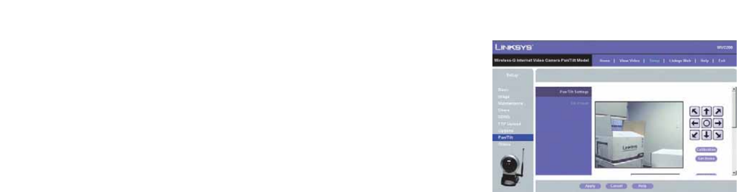
54
Chapter 7: Using the Wireless-G Internet Camera’s Web-based Utility
Setup
Wireless-G PTZ Internet Camera with Audio
Pan/Tilt
The Pan/Tilt screen allows you to manage the Camera’s preset positions as well as the pan and tile.
Set Positions. Set the desired position through adjusting the control panel.
Calibration. Click this button to reset the calibration of Pan/Tilt area.
Set Home. Set the desired position and then click this button to set Home position.
Current Position. Name the current desired position and then click the Add button to add into the preset list.
Preset Positions. Select the preset position you don't need and then click the Delete button to remove.
Pan/Tilt Movement. Enable this if you want to use the Pan/Tilt Movement feature.
Reset. Click this button to reset Default Home Position.
Preset Rotation Sequence. This feature determines how the camera will move when it is set to Rotate. You can
set a number of Preset Positions; the camera will go to the first position, then move through the list of present
positions until it is finished. The camera will stop at the last position in the list.
To create the Preset Sequence, select the desired Preset Position in the left column, select the desired time to
remain at this position, and click the Add >> button. Repeat until the desired sequence is complete.
To delete a position from the Sequence, select the desired position and click the Delete button.
To save your changes, click the Apply button. To cancel any unsaved changes, click the Cancel button. To get
additional information about the screen’s features, click the Help button.
Figure 7-14: Pan/Tilt Screen
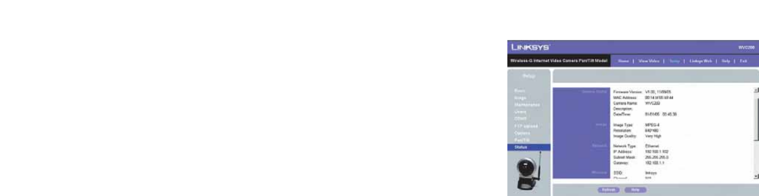
55
Chapter 7: Using the Wireless-G Internet Camera’s Web-based Utility
Setup
Wireless-G PTZ Internet Camera with Audio
Status
The Status screen allows you to view the Camera’s status information and log.
System
Firmware Version. The version of the current firmware installed.
MAC Address. The MAC Address of the Camera is displayed here.
Camera Name. The name you gave to the Camera is displayed here.
Description. Information about the Camera, such as location, is displayed here.
Date/Time. The current date and time are shown here.
Image
Image Type. This displays the compression type of the video stream.
Resolution. This displays the image size of the video stream.
Image Quality. This displays the image quality of the video stream.
Network
Network Type. The wireless network’s mode is shown here.
IP Address. The Camera’s IP Address is displayed here.
Subnet Mask. The Camera’s Subnet Mask is shown here.
Gateway. The Camera’s Gateway address is displayed here.
Wireless
SSID. The wireless network’s SSID or name is shown here.
Channel. The wireless network’s channel setting is displayed here.
Security. The wireless network’s encryption level is shown here.
Figure 7-15: Status Screen
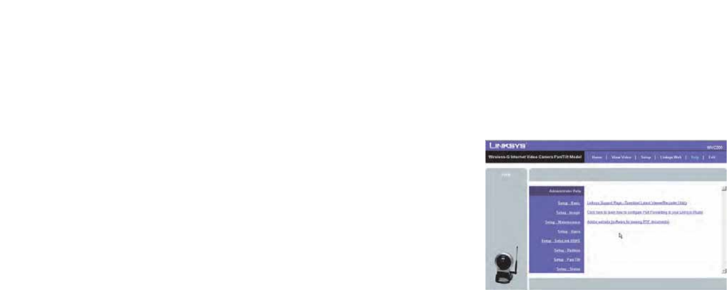
56
Chapter 7: Using the Wireless-G Internet Camera’s Web-based Utility
Help
Wireless-G PTZ Internet Camera with Audio
Log
System Log. This shows the Camera’s activities. To empty the log, click the Clear Log button.
System Log Server. This allows the Camera to upload System Log files to a System Log Server.
To get the Camera’s most up-to-date information, click the Refresh button. To get additional information about
the screen’s features, click the Help button.
Help
Through the Help screen, you’ll find links to additional resources for the Camera and its Utility. If you click the
Help tab directly from the Welcome screen, then you will see the User Help screen and will only be able to access
these resources. If you first log in to access the Camera’s Setup and then click the Help tab, you will see the
Administrator Help screen and will be able to restore factory defaults and upgrade the Camera’s firmware.
Setup. Click any of the topics in the bar on the left to get help information.
Linksys Support Page - Download Latest Viewer/Recorder Utility. Click this link to download the most recent
version of the Viewer & Recorder Utility from the Linksys website, www.linksys.com.
Click here to learn how to configure Port Forwarding in your Linksys Router. If you are going to use the
SoloLink DDNS Service, you need to set up port forwarding on your router. For instructions on how to configure a
Linksys router, click this link. If you have a different router, refer to your router’s documentation.
Online User Guide in PDF Format and Adobe website (software for viewing PDF documents). Click the
Online User Guide in PDF Format link to view the latest version of the Camera’s user guide. It will be in Adobe
Acrobat Portable Document File (.pdf) format, so you will need Acrobat Reader to view this pdf. If you do not have
the Acrobat Reader, click the Adobe website link to download it.
Figure 7-16: Help Screen

57
Appendix A: Troubleshooting
Wireless-G PTZ Internet Camera with Audio
Appendix A: Troubleshooting
This appendix provides solutions to problems that may occur during the installation and operation of the
Wireless-G Internet Camera. Read the description below to solve your problems. If you can't find an answer here,
check the Linksys website at www.linksys.com.
1. I can't connect to the Wireless Network Camera with my Web Browser to configure it.
It is possible that your PC's IP address is not compatible with the IP address of the Wireless Network Camera.
Use the Windows utility to configure the Wireless Network Camera with a valid IP address.
2. The Windows utility doesn't list any Wireless Network Cameras.
Check the following:
• The Wireless Network Camera is installed, LAN connections are OK, it is powered ON and startup is
complete.
• Ensure that your PC and the Wireless Network Camera are on the same network segment. (If you don't
have a router, this could be the case.)
• Ensure that your PC has the TCP/IP network protocol loaded. In Windows, this is done by using Control
Panel-Network.
If an entry for TCP/IP -> Network card is not listed, use Add - Protocol - Microsoft - TCP/IP to add it. You then
need to select the new entry (TCP/IP -> Network card), click Properties, and configure the IP Address tab. If
your LAN has a DHCP Server, you can select "Obtain an IP Address automatically". Otherwise, you must select
"Specify an IP Address", and enter values for IP Address, Subnet Mask, and Gateway. All devices on your LAN
must use compatible values. Remember that each device needs a unique IP Address, and the same Subnet
Mask.
3. When I try to connect to the Wireless Network Camera, I get prompted for a user name and
password.
You SHOULD be prompted for a user name and password when you first connect to the camera. Enter the
Administrator ID and Password set on the User screen. The Username/Password prompt indicates that the
Administrator has restricted access to specified users. Ask the Administrator for your Username and
Password.

58
Appendix A: Troubleshooting
Wireless-G PTZ Internet Camera with Audio
4. I can't connect to the Wireless Network Camera using a Wireless connection.
If a LAN cable is connected to the LAN port, the Wireless interface is disabled. Only one interface can be
active.
Check that your PC and the Wireless Network Camera have compatible Wireless settings.
• Mode (Infrastructure or Ad-hoc) must be correct.
• ESSID must match.
• WEP settings must match.
• In Ad-hoc mode, the Channel should match, although this is often not required.
5. Video quality may suddenly deteriorate.
This can happen when an additional viewer connects to the Wireless Network Camera, overloading the
camera or the available bandwidth. The image size and quality can be adjusted to cater for the required
number of viewers and the available bandwidth.
6. The motion detection feature doesn't send me any E-mails.
It may be that the SMTP (Simple Mail Transport Protocol) server used by the camera to send the E-mail will
not accept mail. (This is to prevent Spam being sent from the server.). Try using a different SMTP server, or
contact your ISP to see if SMTP access is being blocked.
7. Using the motion detection feature, I receive E-mails which don't show any moving objects.
The motion detection feature doesn't actually detect motion. It compares frames to see if they are different.
Major differences between frames are assumed to be caused by moving objects.
But the motion detector can also be triggered by sudden changes in the level of available light or movement
of the camera itself.
Try to avoid these situations. The motion detection feature works best in locations where there is good steady
illumination, and the camera is mounted securely. This feature can NOT be used if the camera is outdoors.
8. The image is blurry.
Try cleaning the dome, or adjusting the Image Quality setting on the Image screen. Video created will the
lower settings will contain less detail; this is the trade-off for using less bandwidth.

59
Appendix B: Wireless Security
Security Precautions
Wireless-G PTZ Internet Camera with Audio
Appendix B: Wireless Security
Linksys wants to make wireless networking as safe and easy for you as possible. The current generation of
Linksys products provide several network security features, but they require specific action on your part for
implementation. So, keep the following in mind whenever you are setting up or using your wireless network.
Security Precautions
The following is a complete list of security precautions to take (at least steps 1 through 5 should be followed):
1. Change the default SSID.
2. Disable SSID Broadcast.
3. Change the default password for the Administrator account.
4. Change the SSID periodically.
5. Use the highest encryption algorithm possible. Use WPA if it is available. Please note that this may reduce
your network performance.
6. Change the WEP encryption keys periodically.
Security Threats Facing Wireless Networks
Wireless networks are easy to find. Hackers know that in order to join a wireless network, wireless networking
products first listen for “beacon messages”. These messages can be easily decrypted and contain much of the
network’s information, such as the network’s SSID (Service Set Identifier). Here are the steps you can take:
Change the administrator’s password regularly. With every wireless networking device you use, keep in mind
that network settings (SSID, WEP keys, etc.) are stored in its firmware. Your network administrator is the only
person who can change network settings. If a hacker gets a hold of the administrator’s password, he, too, can
change those settings. So, make it harder for a hacker to get that information. Change the administrator’s
password regularly.
Note: Some of these security features are available
only through the network router or access point. Refer
to the router or access point’s documentation for more
information.

60
Appendix B: Wireless Security
Security Threats Facing Wireless Networks
Wireless-G PTZ Internet Camera with Audio
SSID. There are several things to keep in mind about the SSID:
1. Disable Broadcast
2. Make it unique
3. Change it often
Most wireless networking devices will give you the option of broadcasting the SSID. While this option may be
more convenient, it allows anyone to log into your wireless network. This includes hackers. So, don’t broadcast
the SSID.
Wireless networking products come with a default SSID set by the factory. (The Linksys default SSID is “linksys”.)
Hackers know these defaults and can check these against your network. Change your SSID to something unique
and not something related to your company or the networking products you use.
Change your SSID regularly so that any hackers who have gained access to your wireless network will have to
start from the beginning in trying to break in.
MAC Addresses. Enable MAC Address filtering. MAC Address filtering will allow you to provide access to only
those wireless nodes with certain MAC Addresses. This makes it harder for a hacker to access your network with
a random MAC Address.
WEP Encryption. Wired Equivalent Privacy (WEP) is often looked upon as a cure-all for wireless security
concerns. This is overstating WEP’s ability. Again, this can only provide enough security to make a hacker’s job
more difficult.
There are several ways that WEP can be maximized:
1. Use the highest level of encryption possible
2. Use “Shared Key” authentication
3. Change your WEP key regularly
Implementing encryption may have a negative impact on your network’s performance, but if you are transmitting
sensitive data over your network, encryption should be used.
These security recommendations should help keep your mind at ease while you are enjoying the most flexible
and convenient technology Linksys has to offer.
Important: Always remember that each device in
your wireless network MUST use the same encryption
method and encryption key or your wireless network
will not function properly.
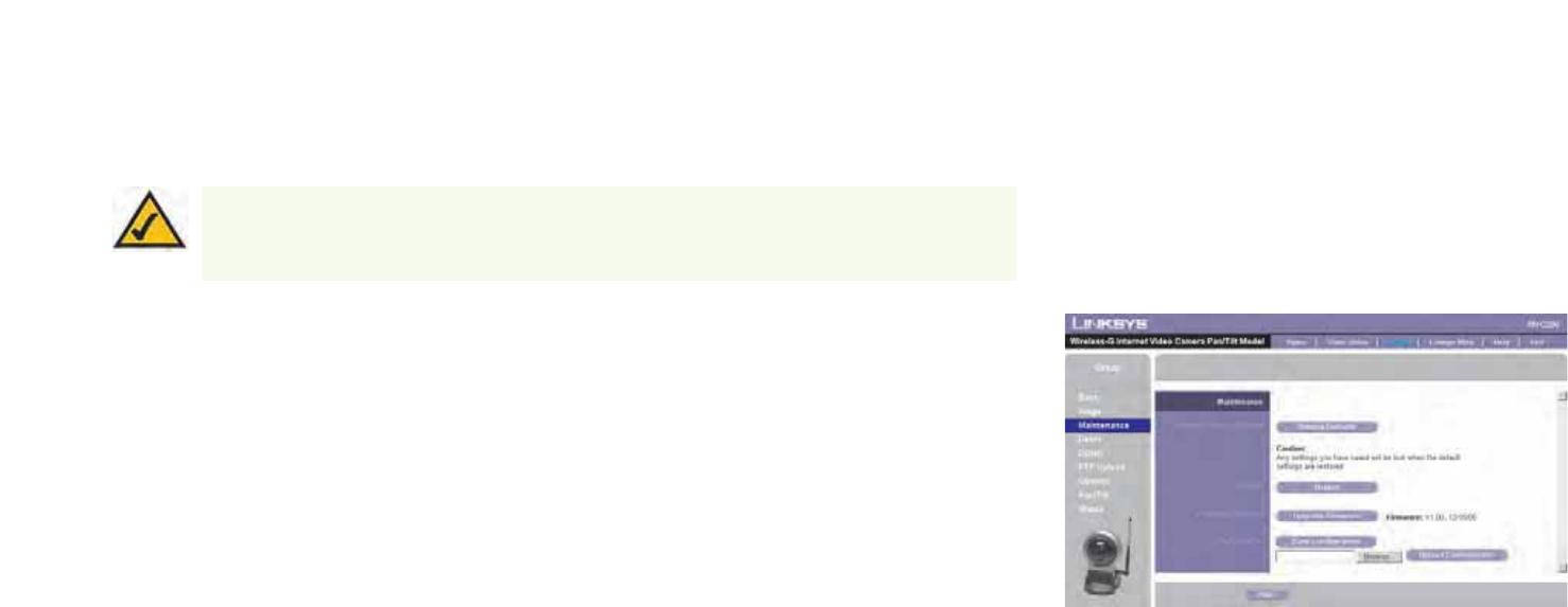
61
Appendix C: Upgrading Firmware
Wireless-G PTZ Internet Camera with Audio
Appendix C: Upgrading Firmware
The Camera's firmware is upgraded through the Web-based Utility's Maintenance tab. Follow these instructions:
1. Download the firmware from Linksys’s website at www.linksys.com. Then extract the file.
2. Access the Camera’s Web-based Utility, and click the Maintenance tab.
3. On the Maintenance screen, click the Firmware Upgrade button.
4. Click the Browse button to find the extracted file, and then double-click the filename.
5. Click the Start Upgrade button, and follow the on-screen instructions. Click the Cancel button to cancel the
firmware upgrade. For more information, click the Help button.
Figure C-1: Upgrade Firmware Screen
Note: Linksys recommends that you upgrade the Camera’s firmware within your network; in other
words, use a computer within the Camera’s local network. If you attempt to upgrade the Camera’s
firmware from a remote location—using a computer outside of the Camera’s local network—the
upgrade will fail.

62
Appendix D: vWindows Help
Wireless-G PTZ Internet Camera with Audio
Appendix D: vWindows Help
Almost all wireless products require Microsoft Windows. Windows is the most used operating system in the world
and comes with many features that help make networking easier. These features can be accessed through
Windows Help and are described in this appendix.
TCP/IP
Before a computer can communicate with an access point or router, TCP/IP must be enabled. TCP/IP is a set of
instructions, or protocol, all PCs follow to communicate over a network. This is true for wireless networks as well.
Your PCs will not be able to utilize wireless networking without having TCP/IP enabled. Windows Help provides
complete instructions on enabling TCP/IP.
Shared Resources
If you wish to share printers, folders, or files over your network, Windows Help provides complete instructions on
using shared resources.
Network Neighborhood/My Network Places
Other PCs on your network will appear under Network Neighborhood or My Network Places (depending upon the
version of Windows you’re running). Windows Help provides complete instructions on adding PCs to your
network.

63
Appendix E: Glossary
Wireless-G PTZ Internet Camera with Audio
Appendix E: Glossary
This glossary contains some basic networking terms you may come across when using this product. For more
advanced terms, see the complete Linksys glossary at http://www.linksys.com/glossary.
Access Point - A device that allows wireless-equipped computers and other devices to communicate with a
wired network. Also used to expand the range of a wireless network.
Ad-hoc - A group of wireless devices communicating directly with each other (peer-to-peer) without the use of
an access point.
AES (Advanced Encryption Standard) - A security method that uses symmetric 128-bit block data encryption.
Bandwidth - The transmission capacity of a given device or network.
Bit - A binary digit.
Boot - To start a device and cause it to start executing instructions.
Broadband - An always-on, fast Internet connection.
Browser - An application program that provides a way to look at and interact with all the information on the
World Wide Web.
Byte - A unit of data that is eight bits long
Cable Modem - A device that connects a computer to the cable television network, which in turn connects to the
Internet.
Daisy Chain - A method used to connect devices in a series, one after the other.
DDNS (Dynamic Domain Name System) - Allows the hosting of a website, FTP server, or e-mail server with a
fixed domain name (e.g., www.xyz.com) and a dynamic IP address.
Default Gateway - A device that forwards Internet traffic from your local area network.
DHCP (Dynamic Host Configuration Protocol) - A networking protocol that allows administrators to assign
temporary IP addresses to network computers by "leasing" an IP address to a user for a limited amount of time,
instead of assigning permanent IP addresses.

64
Appendix E: Glossary
Wireless-G PTZ Internet Camera with Audio
DMZ (Demilitarized Zone) - Removes the Router's firewall protection from one PC, allowing it to be "seen" from
the Internet.
DNS (Domain Name Server) - The IP address of your ISP's server, which translates the names of websites into IP
addresses.
Domain - A specific name for a network of computers.
Download - To receive a file transmitted over a network.
DSL (Digital Subscriber Line) - An always-on broadband connection over traditional phone lines.
Dynamic IP Address - A temporary IP address assigned by a DHCP server.
EAP (Extensible Authentication Protocol) - A general authentication protocol used to control network access.
Many specific authentication methods work within this framework.
Encryption - Encoding data transmitted in a network.
Ethernet - IEEE standard network protocol that specifies how data is placed on and retrieved from a common
transmission medium.
Firewall - A set of related programs located at a network gateway server that protects the resources of a
network from users from other networks.
Firmware - The programming code that runs a networking device.
FTP (File Transfer Protocol) - A protocol used to transfer files over a TCP/IP network.
Full Duplex - The ability of a networking device to receive and transmit data simultaneously.
Gateway - A device that interconnects networks with different, incompatible communications protocols.
Half Duplex - Data transmission that can occur in two directions over a single line, but only one direction at a
time.
HTTP (HyperText Transport Protocol) - The communications protocol used to connect to servers on the World
Wide Web.
Infrastructure - A wireless network that is bridged to a wired network via an access point.
IP (Internet Protocol) - A protocol used to send data over a network.

65
Appendix E: Glossary
Wireless-G PTZ Internet Camera with Audio
IP Address - The address used to identify a computer or device on a network.
IPCONFIG - A Windows 2000 and XP utility that displays the IP address for a particular networking device.
IPSec (Internet Protocol Security) - A VPN protocol used to implement secure exchange of packets at the IP layer.
ISP (Internet Service Provider) - A company that provides access to the Internet.
LAN - The computers and networking products that make up your local network.
MAC (Media Access Control) Address - The unique address that a manufacturer assigns to each networking
device.
Mbps (MegaBits Per Second) - One million bits per second; a unit of measurement for data transmission.
NAT (Network Address Translation) - NAT technology translates IP addresses of a local area network to a different
IP address for the Internet.
Network - A series of computers or devices connected for the purpose of data sharing, storage, and/or
transmission between users.
Packet - A unit of data sent over a network.
Passphrase - Used much like a password, a passphrase simplifies the WEP encryption process by automatically
generating the WEP encryption keys for Linksys products.
Ping (Packet INternet Groper) - An Internet utility used to determine whether a particular IP address is online.
POP3 (Post Office Protocol 3) - A standard mail server commonly used on the Internet.
Port - The connection point on a computer or networking device used for plugging in cables or adapters.
Power over Ethernet (PoE) - A technology enabling an Ethernet network cable to deliver both data and power.
PPPoE (Point to Point Protocol over Ethernet) - A type of broadband connection that provides authentication
(username and password) in addition to data transport.
PPTP (Point-to-Point Tunneling Protocol) - A VPN protocol that allows the Point to Point Protocol (PPP) to be
tunneled through an IP network. This protocol is also used as a type of broadband connection in Europe.
RADIUS (Remote Authentication Dial-In User Service) - A protocol that uses an authentication server to control
network access.

66
Appendix E: Glossary
Wireless-G PTZ Internet Camera with Audio
RJ-45 (Registered Jack-45) - An Ethernet connector that holds up to eight wires.
Roaming - The ability to take a wireless device from one access point's range to another without losing the
connection.
Router - A networking device that connects multiple networks together.
Server - Any computer whose function in a network is to provide user access to files, printing, communications,
and other services.
SMTP (Simple Mail Transfer Protocol) - The standard e-mail protocol on the Internet.
SNMP (Simple Network Management Protocol) - A widely used network monitoring and control protocol.
SPI (Stateful Packet Inspection) Firewall - A technology that inspects incoming packets of information before
allowing them to enter the network.
SSID (Service Set IDentifier) - Your wireless network's name.
Static IP Address - A fixed address assigned to a computer or device that is connected to a network.
Static Routing - Forwarding data in a network via a fixed path.
Subnet Mask - An address code that determines the size of the network.
Switch - 1. A data switch that connects computing devices to host computers, allowing a large number of
devices to share a limited number of ports. 2. A device for making, breaking, or changing the connections in an
electrical circuit.
TCP (Transmission Control Protocol) - A network protocol for transmitting data that requires acknowledgement
from the recipient of data sent.
TCP/IP (Transmission Control Protocol/Internet Protocol) - A set of instructions PCs use to communicate over a
network.
Telnet - A user command and TCP/IP protocol used for accessing remote PCs.
TFTP (Trivial File Transfer Protocol) - A version of the TCP/IP FTP protocol that has no directory or password
capability.
Throughput - The amount of data moved successfully from one node to another in a given time period.

67
Appendix E: Glossary
Wireless-G PTZ Internet Camera with Audio
TKIP (Temporal Key Integrity Protocol) - a wireless encryption protocol that provides dynamic encryption keys for
each packet transmitted.
Topology - The physical layout of a network.
TX Rate - Transmission Rate.
Upgrade - To replace existing software or firmware with a newer version.
Upload - To transmit a file over a network.
URL (Uniform Resource Locator) - The address of a file located on the Internet.
VPN (Virtual Private Network) - A security measure to protect data as it leaves one network and goes to another
over the Internet.
WAN (Wide Area Network)- The Internet.
WEP (Wired Equivalent Privacy) - A method of encrypting network data transmitted on a wireless network for
greater security.
WLAN (Wireless Local Area Network) - A group of computers and associated devices that communicate with
each other wirelessly.
WPA (Wi-Fi Protected Access) - a wireless security protocol using TKIP (Temporal Key Integrity Protocol)
encryption, which can be used in conjunction with a RADIUS server.

68
Appendix F: Specifications
Wireless-G PTZ Internet Camera with Audio
Appendix F: Specifications
Standards IEEE802.11g, IEEE802.11b, IEEE802.3, IEEE802.3u, 802.11e (Wireless QoS)
Ports Ethernet, Antenna, Microphone, Power
Protocols TCP/IP, HTTP, DHCP, SMTP, FTP, NTP, DNS, UPnP and DDNS
Button One Reset Button
Cabling Type UTP CAT 5
LEDs Power, Ethernet, Wireless-G
Sensor 1/5" CMOS
Focal Length 500mm~Infinity
Frame Rate Up to 30 fps
Resolution 640x480, 320x240, 160x120
Illumination 2LUX@F2.0
Field of View 60 degrees
Auto Patrol 9 Definable Preset Points by User
Pan ± 67 degrees
Tilt -34 degrees (down) to +30 degrees (up)
WebUI Built in Web UI for Easy Browser-Based Configuration (HTTP)

69
Appendix F: Specifications
Wireless-G PTZ Internet Camera with Audio
Web Browser Internet Explorer 5.x, or Above
Event Logging Event Logging
Web F/W Upgrade Firmware Upgradable Through Web-Browser
Dual Codec MPEG-4 Simple Profile, MJPEG
Snapshot JPEG
Modulation NTSC and PAL
Image Position Flip and Mirror
Image Settings Brightness and Contrast
Night Vision IR Filter cut for low light
Motion Detection Send Video Clip to an email address on motion detection
Compression G.726
Sampling Rate 8 KHz
Dual Bit Rate 16Kbps
Brightness Auto/Manual Adjustment
Monitor and Recording Software Included software for multiple camera monitoring and recording to your hard drive with advanced search by time
and date. Recording can be set up to record by motion trigger, manual or schedule recording and playback on
Windows Media Player without the need for a proprietary player.
WEP/WPA WEP 64bit/128bit, WPA-TKIP, WPA-PSK

70
Appendix F: Specifications
Wireless-G PTZ Internet Camera with Audio
User List User Rights List to View Video and/or to Camera Control Functions
Username/Password Logon authentication 20 characters username and 8 characters password
NTP Network Time Protocol
SMTP Simple Mail Transfer Protocol Client allows video clips to be emailed
FTP Client FTP Client facilitates scheduling transfer of images to an FTP server
DDNS Dynamic DNS facilitates reaching the camera by a name irrespective of what the IP address is. Sololink, DynDNs,
and TZO is supported
UPnP Allows autodiscovery of the camera by other UPnP devices
Dimensions 1.26" x 7.83" x 6.89"
(W x H x D) (32 mm x 199 mm x 175 mm)
Unit Weight 1.01 lbs. (0.46 kg)
Power 5DVC 2.5A Switching Power Supply
Certifications FCC, CE and UL
Operating Temp. 0 ºC to 40 ºC (-32 ºF to 104 ºF)
Storage Temp. -20 ºC to 70 ºC (-4 ºF to 140 ºF)
Operating Humidity 10% to 80%, Non-Condensing
Storage Humidity 0% to 90%, Non-Condensing

71
Appendix G: Warranty Information
Wireless-G PTZ Internet Camera with Audio
Appendix G: Warranty Information
LIMITED WARRANTY
Linksys warrants to You that, for a period of three years (the “Warranty Period”), your Linksys Product will be substantially
free of defects in materials and workmanship under normal use. Your exclusive remedy and Linksys' entire liability under
this warranty will be for Linksys at its option to repair or replace the Product or refund Your purchase price less any
rebates. This limited warranty extends only to the original purchaser.
If the Product proves defective during the Warranty Period call Linksys Technical Support in order to obtain a Return
Authorization Number, if applicable. BE SURE TO HAVE YOUR PROOF OF PURCHASE ON HAND WHEN CALLING. If You are
requested to return the Product, mark the Return Authorization Number clearly on the outside of the package and include a
copy of your original proof of purchase. RETURN REQUESTS CANNOT BE PROCESSED WITHOUT PROOF OF PURCHASE. You
are responsible for shipping defective Products to Linksys. Linksys pays for UPS Ground shipping from Linksys back to You
only. Customers located outside of the United States of America and Canada are responsible for all shipping and handling
charges.
ALL IMPLIED WARRANTIES AND CONDITIONS OF MERCHANTABILITY OR FITNESS FOR A PARTICULAR PURPOSE ARE LIMITED
TO THE DURATION OF THE WARRANTY PERIOD. ALL OTHER EXPRESS OR IMPLIED CONDITIONS, REPRESENTATIONS AND
WARRANTIES, INCLUDING ANY IMPLIED WARRANTY OF NON-INFRINGEMENT, ARE DISCLAIMED. Some jurisdictions do not
allow limitations on how long an implied warranty lasts, so the above limitation may not apply to You. This warranty gives
You specific legal rights, and You may also have other rights which vary by jurisdiction.
This warranty does not apply if the Product (a) has been altered, except by Linksys, (b) has not been installed, operated,
repaired, or maintained in accordance with instructions supplied by Linksys, or (c) has been subjected to abnormal
physical or electrical stress, misuse, negligence, or accident. In addition, due to the continual development of new
techniques for intruding upon and attacking networks, Linksys does not warrant that the Product will be free of
vulnerability to intrusion or attack.
TO THE EXTENT NOT PROHIBITED BY LAW, IN NO EVENT WILL LINKSYS BE LIABLE FOR ANY LOST DATA, REVENUE OR PROFIT,
OR FOR SPECIAL, INDIRECT, CONSEQUENTIAL, INCIDENTAL OR PUNITIVE DAMAGES, REGARDLESS OF THE THEORY OF
LIABILITY (INCLUDING NEGLIGENCE), ARISING OUT OF OR RELATED TO THE USE OF OR INABILITY TO USE THE PRODUCT
(INCLUDING ANY SOFTWARE), EVEN IF LINKSYS HAS BEEN ADVISED OF THE POSSIBILITY OF SUCH DAMAGES. IN NO EVENT
WILL LINKSYS’ LIABILITY EXCEED THE AMOUNT PAID BY YOU FOR THE PRODUCT. The foregoing limitations will apply even
if any warranty or remedy provided under this Agreement fails of its essential purpose. Some jurisdictions do not allow the
exclusion or limitation of incidental or consequential damages, so the above limitation or exclusion may not apply to You.
Please direct all inquiries to: Linksys, P.O. Box 18558, Irvine, CA 92623.

72
Appendix H: Regulatory Information
Wireless-G PTZ Internet Camera with Audio
Appendix H: Regulatory Information
FCC Statement
This equipment has been tested and found to comply with the limits for a Class B digital device, pursuant to Part 15 of the
FCC Rules. These limits are designed to provide reasonable protection against harmful interference in a residential
installation. This equipment generates, uses and can radiate radio frequency energy and, if not installed and used in
accordance with the instructions, may cause harmful interference to radio communications. However, there is no
guarantee that interference will not occur in a particular installation. If this equipment does cause harmful interference to
radio or television reception, which can be determined by turning the equipment off and on, the user is encouraged to try
to correct the interference by one of the following measures:
• Reorient or relocate the receiving antenna.
• Increase the separation between the equipment and receiver.
• Connect the equipment into an outlet on a circuit different from that to which the receiver is connected.
• Consult the dealer or an experienced radio/TV technician for help.
This device complies with Part 15 of the FCC Rules. Operation is subject to the following two conditions: (1) This device
may not cause harmful interference, and (2) this device must accept any interference received, including interference that
may cause undesired operation.
FCC Caution
Any changes or modifications not expressly approved by the party responsible for compliance could void the user's
authority to operate this equipment.
FCC Radiation Exposure Statement
This equipment complies with FCC radiation exposure limits set forth for an uncontrolled environment. This equipment
should be installed and operated with minimum distance 20cm between the radiator & your body. To maintain compliance
with FCC RF exposure compliance requirements, please avoid direct contact to the transmitting antenna during
transmitting.
This transmitter must not be co-located or operating in conjunction with any other antenna or transmitter.
We declare that the product is limited in CH1~CH11 by specified firmware controlled in the USA.

73
Appendix H: Regulatory Information
Wireless-G PTZ Internet Camera with Audio
Safety Notices
Do not use this product near water, for example, in a wet basement or near a swimming pool.
Avoid using this product during an electrical storm. There may be a remote risk of electric shock from lightning.
Industry Canada (Canada)
Operation is subject to the following two conditions:
1) This device may not cause interference and
2) This device must accept any interference, including interference that may cause undesired operation of the device.
This device has been designed to operate with an antenna having a maximum gain of 3.3 dBi. Antenna having a higher gain
is strictly prohibited per regulations of Industry Canada. The required antenna impedance is 50 ohms.
This device complies with Canadian ICES-003 and RSS210 rules.
Cet appareil est conforme aux normes NMB-003 et RSS210 d'Industry Canada.
Caution: Risk of explosion if battery is replaced by an incorrect
type. Dispose of used batteries according to the instructions.
74
Appendix H: Regulatory Information
Wireless-G PTZ Internet Camera with Audio
User Information for Consumer Products Covered by EU Directive 2002/96/EC on Waste Electric and Electronic
Equipment (WEEE)
This document contains important information for users with regards to the proper disposal and recycling of Linksys
products. Consumers are required to comply with this notice for all electronic products bearing the following symbol:
75
Appendix H: Regulatory Information
Wireless-G PTZ Internet Camera with Audio

76
Appendix H: Regulatory Information
Wireless-G PTZ Internet Camera with Audio
77
Appendix H: Regulatory Information
Wireless-G PTZ Internet Camera with Audio
78
Appendix H: Regulatory Information
Wireless-G PTZ Internet Camera with Audio
For more information, visit www.linksys.com.

79
Appendix I: Contact Information
Wireless-G PTZ Internet Camera with Audio
Appendix I: Contact Information
Need to contact Linksys?
Visit us online for information on the latest products and updates
to your existing products at: http://www.linksys.com or
ftp.linksys.com
Can't find information about a product you want to buy
on the web? Do you want to know more about networking
with Linksys products? Give our advice line a call at: 800-546-5797 (LINKSYS)
Or fax your request in to: 949-823-3002
If you experience problems with any Linksys product,
you can call us at: 800-326-7114
Don't wish to call? You can e-mail us at: support@linksys.com
If any Linksys product proves defective during its warranty period,
you can call the Linksys Return Merchandise Authorization
department for obtaining a Return Authorization Number at: 949-823-3000
(Details on Warranty and RMA issues can be found in the Warranty
Information section in this Guide.)