LINKSYS WVC54GC Compact Wireless-G Internet Video Camera User Manual Book
LINKSYS LLC Compact Wireless-G Internet Video Camera Book
UserManual.wiki
>
LINKSYS
>
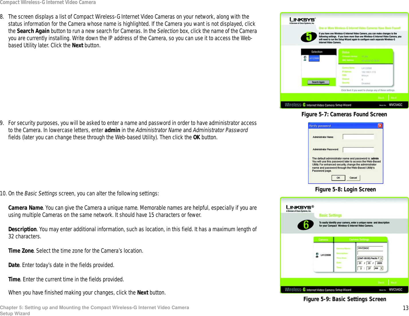
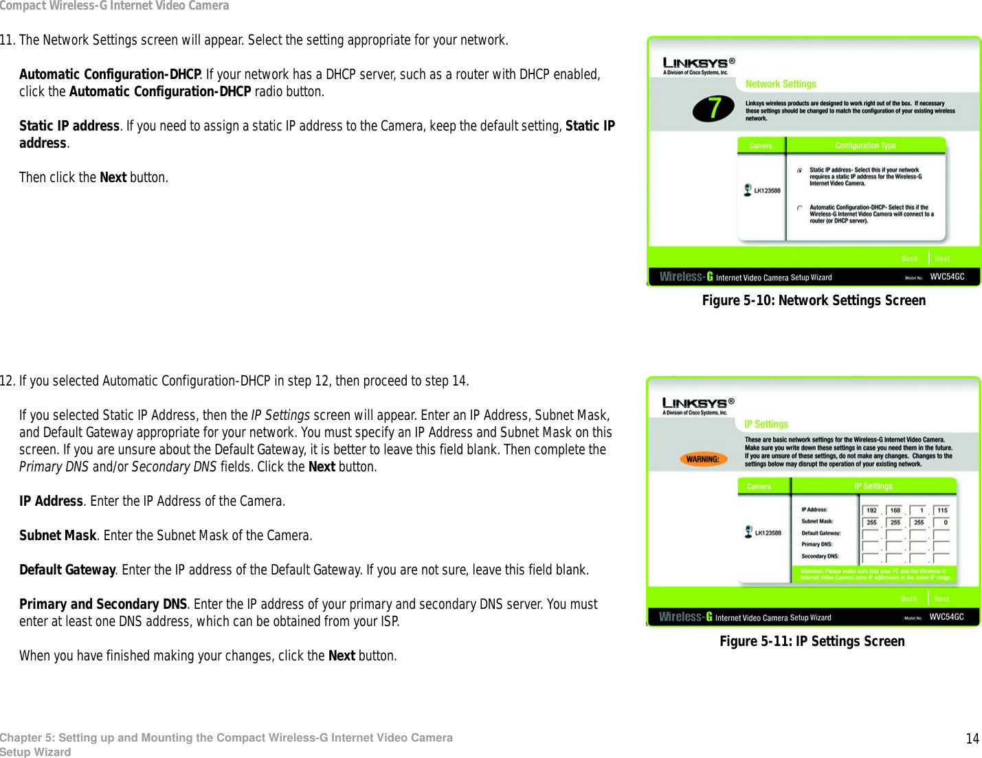
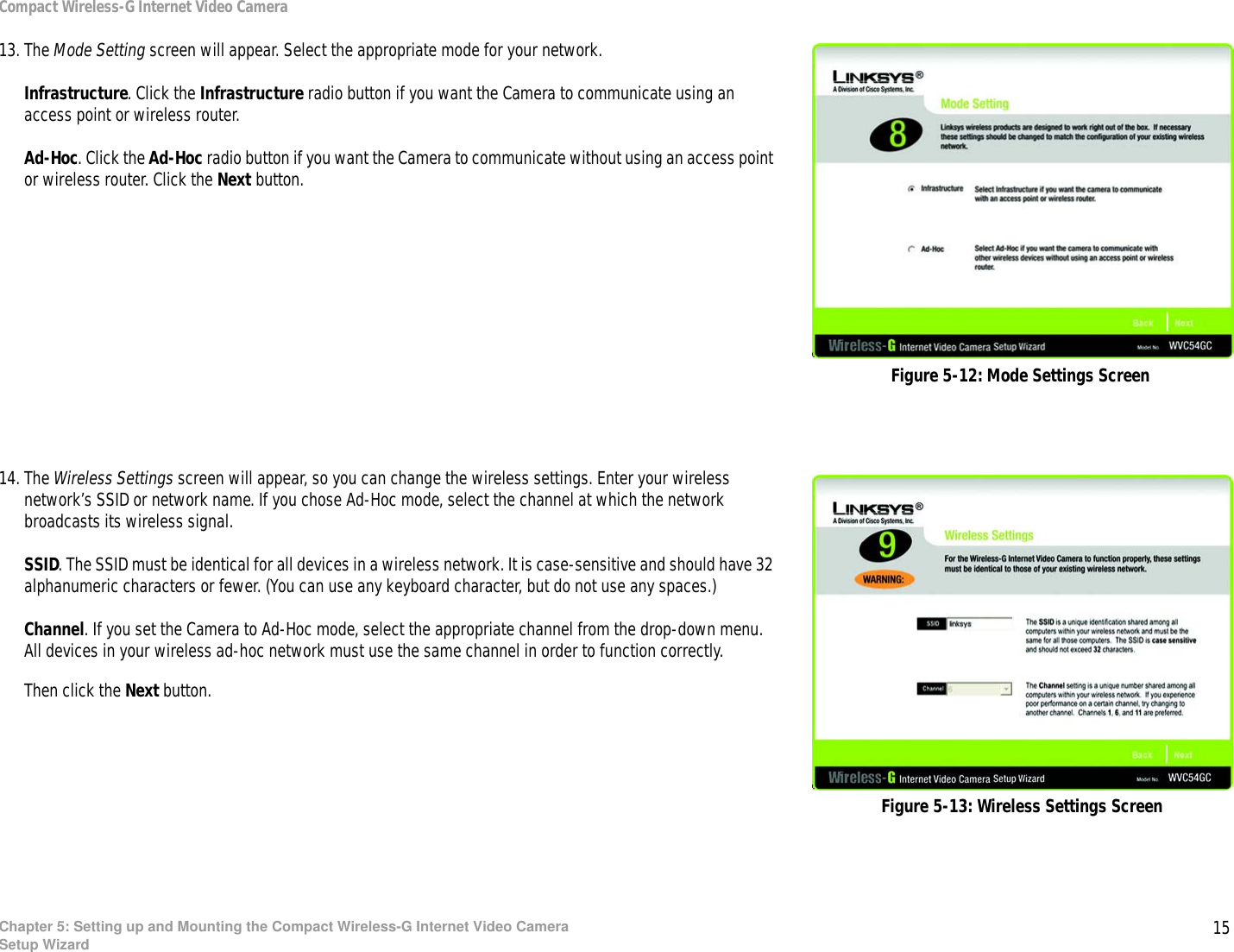
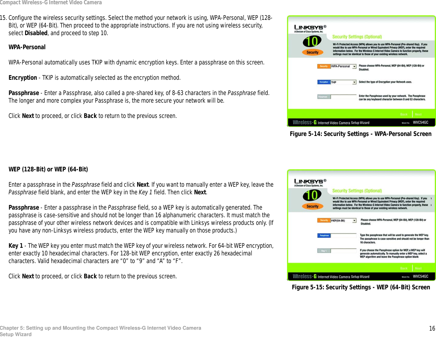
WVC54GC User Manual
Manual
Navigation menu
Upload a User Manual
Namespaces
Wiki Guide
HTML
PDF
Info
Views
User Manual
Discussion / Help
Navigation