LINKSYS WVC80N Wireless-N Internet Home Monitoring Camera User Manual
LINKSYS LLC Wireless-N Internet Home Monitoring Camera
LINKSYS >
User manual
USER GUIDE
Wireless-N Internet
Home Monitoring
Camera
Model: WVC80N
About This Guide
i
Wireless-G Internet Home Monitoring Camera
About This Guide
Icon Descriptions
While reading through the User Guide you may see
various icons that call attention to specific items. Below is
a description of these icons:
NOTE: This check mark indicates that there is
a note of interest and is something that you
should pay special attention to while using the
product.
WARNING: This exclamation point indicates
that there is a caution or warning and it is
something that could damage your property or
product.
WEB: This globe icon indicates a noteworthy
website address or e-mail address.
Online Resources
Website addresses in this document are listed without
http:// in front of the address because most current web
browsers do not require it. If you use an older web browser,
you may have to add http:// in front of the web address.
Resource Website
Linksys www.linksys.com
Linksys International www.linksys.com/international
Glossary www.linksys.com/glossary
Network Security www.linksys.com/security
Copyright and Trademarks
Linksys is a registered trademark or
trademark of Cisco Systems, Inc. and/
or its affiliates in the U.S. and certain
other countries. Copyright © 2007
Cisco Systems, Inc. All rights reserved.
Other brands and product names are
trademarks or registered trademarks
of their respective holders.

Table of Contents
ii
Wireless-G Internet Home Monitoring Camera
Chapter 1: Product Overview 4
Front Panel. . . . . . . . . . . . . . . . . . . . . . . . . . . . . . . . . . . . . . . . . . . . . . . . . . 4
Back Panel . . . . . . . . . . . . . . . . . . . . . . . . . . . . . . . . . . . . . . . . . . . . . . . . . . 4
Bottom Panel . . . . . . . . . . . . . . . . . . . . . . . . . . . . . . . . . . . . . . . . . . . . . . . . 4
Chapter 2: Setting Up and Mounting the Camera 5
Setup Wizard . . . . . . . . . . . . . . . . . . . . . . . . . . . . . . . . . . . . . . . . . . . . . . . . 5
Placement Options . . . . . . . . . . . . . . . . . . . . . . . . . . . . . . . . . . . . . . . . . . . . 9
Chapter 3: Installing and Using the Camera Utility 11
Overview. . . . . . . . . . . . . . . . . . . . . . . . . . . . . . . . . . . . . . . . . . . . . . . . . . .11
Installing the Camera Utility . . . . . . . . . . . . . . . . . . . . . . . . . . . . . . . . . . . . . . .11
Using the Camera Utility for the First Time. . . . . . . . . . . . . . . . . . . . . . . . . . . . . .11
Using the Camera Utility . . . . . . . . . . . . . . . . . . . . . . . . . . . . . . . . . . . . . . . . .12
Chapter 4: Advanced Conguration with the Web-based Utility 19
Overview. . . . . . . . . . . . . . . . . . . . . . . . . . . . . . . . . . . . . . . . . . . . . . . . . . .19
How to Access the Web-based Utility . . . . . . . . . . . . . . . . . . . . . . . . . . . . . . . . .19
View Video . . . . . . . . . . . . . . . . . . . . . . . . . . . . . . . . . . . . . . . . . . . . . . . . . .19
Setup > Basic . . . . . . . . . . . . . . . . . . . . . . . . . . . . . . . . . . . . . . . . . . . . . . . .21
Setup > Image . . . . . . . . . . . . . . . . . . . . . . . . . . . . . . . . . . . . . . . . . . . . . . .22
Setup > Administration. . . . . . . . . . . . . . . . . . . . . . . . . . . . . . . . . . . . . . . . . .23
Setup > Users . . . . . . . . . . . . . . . . . . . . . . . . . . . . . . . . . . . . . . . . . . . . . . . .24
Setup > Options . . . . . . . . . . . . . . . . . . . . . . . . . . . . . . . . . . . . . . . . . . . . . .24
Setup > Motion Detection . . . . . . . . . . . . . . . . . . . . . . . . . . . . . . . . . . . . . . . .25
Setup > Status . . . . . . . . . . . . . . . . . . . . . . . . . . . . . . . . . . . . . . . . . . . . . . .27
Help . . . . . . . . . . . . . . . . . . . . . . . . . . . . . . . . . . . . . . . . . . . . . . . . . . . . . .27
Appendix A: Troubleshooting 29
Common Problems and Solutions . . . . . . . . . . . . . . . . . . . . . . . . . . . . . . . . . . .29
Frequently Asked Questions. . . . . . . . . . . . . . . . . . . . . . . . . . . . . . . . . . . . . . .30
Appendix B: Wireless Security Checklist 32
General Network Security Guidelines . . . . . . . . . . . . . . . . . . . . . . . . . . . . . . . . .32
Additional Security Tips . . . . . . . . . . . . . . . . . . . . . . . . . . . . . . . . . . . . . . . . .32
Appendix C: Specications 33
Appendix D: Warranty Information 34
Appendix E: Regulatory Information 35
FCC Statement . . . . . . . . . . . . . . . . . . . . . . . . . . . . . . . . . . . . . . . . . . . . . . .35
FCC Radiation Exposure Statement . . . . . . . . . . . . . . . . . . . . . . . . . . . . . . . . . .35
Safety Notices. . . . . . . . . . . . . . . . . . . . . . . . . . . . . . . . . . . . . . . . . . . . . . . .35
Industry Canada Statement . . . . . . . . . . . . . . . . . . . . . . . . . . . . . . . . . . . . . . .35
Avis d’Industrie Canada. . . . . . . . . . . . . . . . . . . . . . . . . . . . . . . . . . . . . . . . . .36

Table of Contents
iii
Wireless-G Internet Home Monitoring Camera
Wireless Disclaimer . . . . . . . . . . . . . . . . . . . . . . . . . . . . . . . . . . . . . . . . . . . .36
Avis de non-responsabilité concernant les appareils sans l . . . . . . . . . . . . . . . . . .36
User Information for Consumer Products Covered by EU Directive 2002/96/EC on Waste
Electric and Electronic Equipment (WEEE) . . . . . . . . . . . . . . . . . . . . . . . . . . . . . .37
Chapter 1 Product Overview
4
Wireless-G Internet Home Monitoring Camera
Chapter 1:
Product Overview
Thank you for choosing the Linksys Wireless-G Internet
Home Monitoring Camera. The Camera sends live video
through the Internet to a web browser anywhere in the
world! This compact, self-contained unit lets you keep an
eye on your home, your kids, your workplace—whatever’s
important to you.
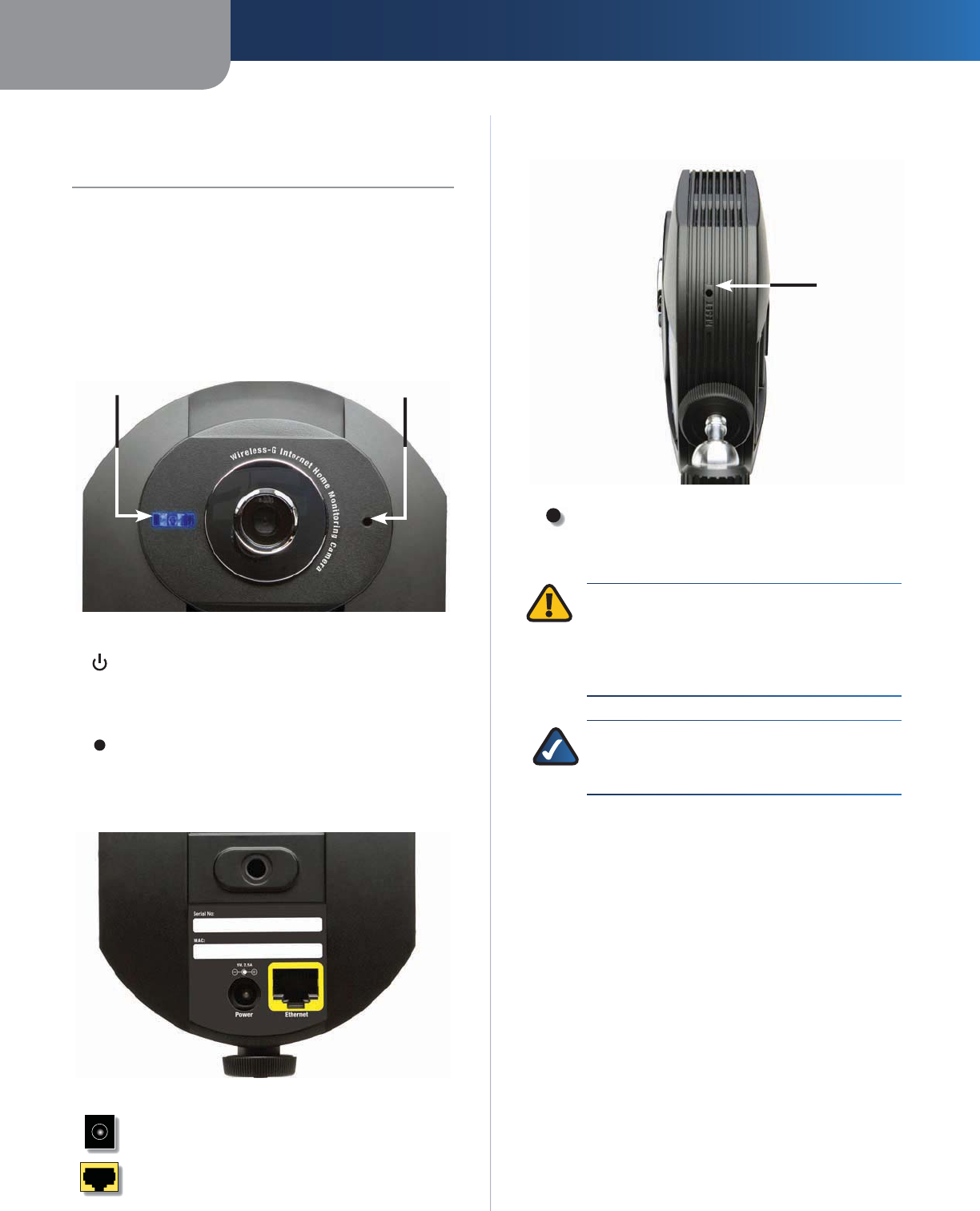
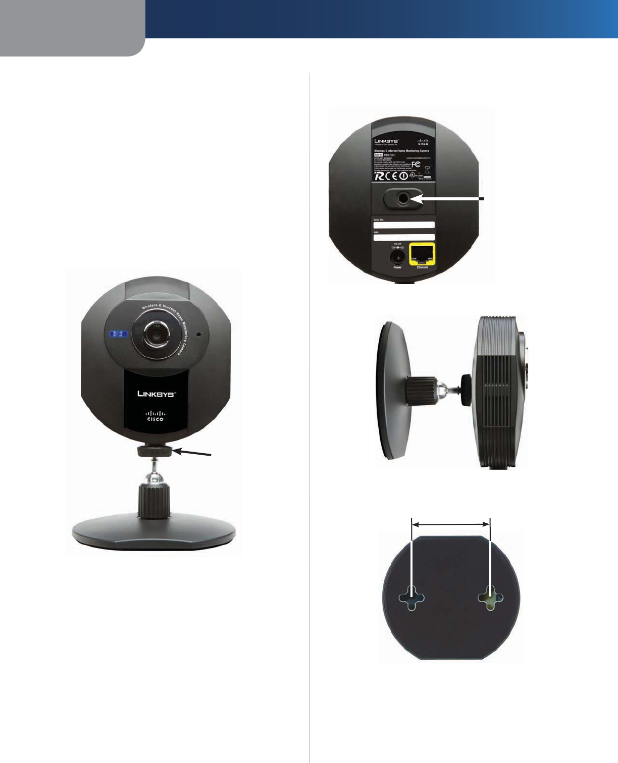
Front Panel
Power LED Microphone
Power (Blue) This LED lights up when the
Camera is powered on. It flashes while the
Camera is booting up and remains lit when the
Camera is ready for use.
Microphone The microphone is used to record
the ambient sound.
Back Panel
Power The Power port is where you will
connect the power adapter.
Ethernet The Ethernet port is where you
connect the Ethernet network cable.
Bottom Panel
Reset Button
Opening
Reset This button is used to reset the Camera.
Insert a paper clip into the opening. Then press
the button and hold it in for five seconds.
WARNING: Resetting the Camera will erase all
of your settings, such as encryption information,
and replace them with the factory defaults. Do
not reset the Camera if you want to retain your
settings.
NOTE:
The Camera’s factory default settings are.
user name: admin
password: admin
Chapter 2 Setting Up and Mounting the Camera
5
Wireless-G Internet Home Monitoring Camera
Chapter 2:
Setting Up and Mounting
the Camera
Setup Wizard
The Wireless-G Internet Home Monitoring Camera Setup
Wizard will guide you through the installation and
configuration procedure.
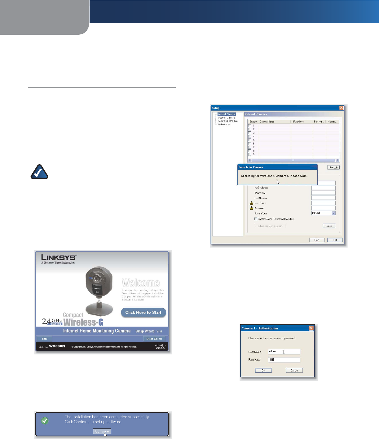
Insert the Setup CD-ROM into your CD-ROM drive.
The Setup Wizard should run automatically, and the
Welcome screen should appear. If not, click Start,
then select Run, and then in the field provided, enter
D:\SetupWizard.exe (if “D” is the letter of your CD-
ROM drive).
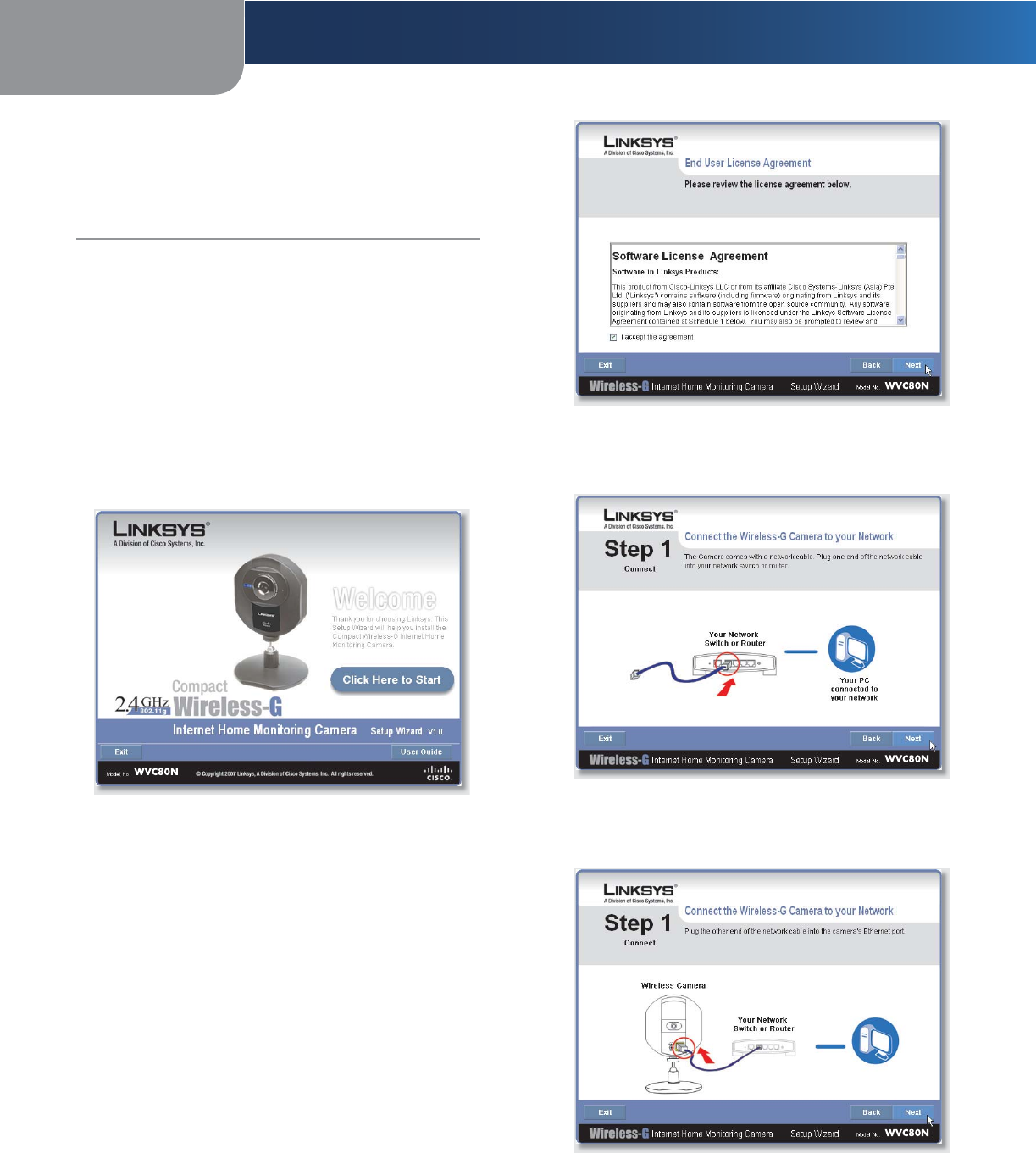
Setup Wizard - Welcome Screen
Click Next, then click Click Here to Start to continue.
The Setup Wizard displays the following options.
Setup Camera Click this to begin the installation
process.
Install Camera Utility Click this to install the Camera
Utility on your PC.
User Guide Click this to open the PDF file of this User
Guide.
Exit Click this to exit the Setup Wizard.
To install the Camera, click Setup Camera.
On the End User License Agreement screen, check the
box next to I accept the agreement and click Next
if you agree and want to continue the installation, or
click Exit to end the installation.
1.
2.
•
•
•
•
3.
End User License Agreement
Connect the included network cable to your network
router or switch. Click Next.
Connect Network Cable to the Switch or Router
Connect the other end of the network cable to the
Camera’s Ethernet port. Click Next.
Connect Network Cable to the Camera
4.
5.
Chapter 2 Setting Up and Mounting the Camera
6
Wireless-G Internet Home Monitoring Camera
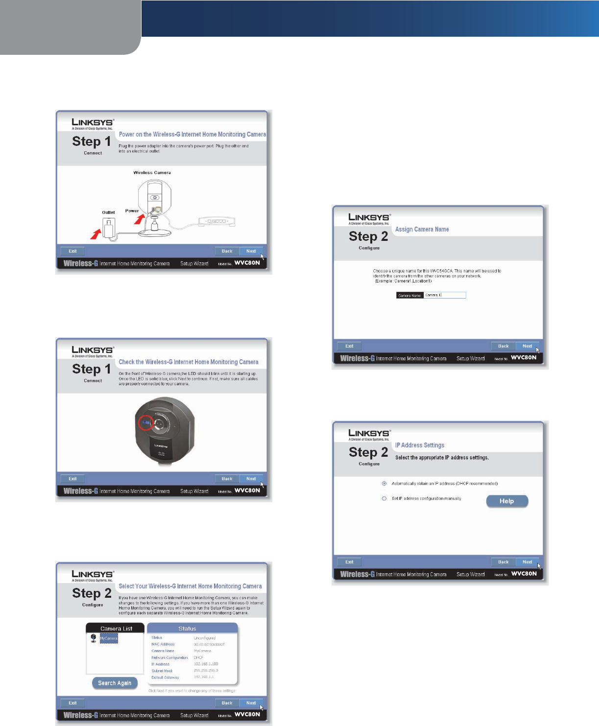
Plug the included power adapter into the Camera’s
Power port. Plug the other end into an electrical outlet.
Click Next.
Power On the Camera
Make sure the LED is lit on the Camera’s front panel. If it
is not lit, make sure the cables are properly connected
to the Camera. Click Next.
Check the LED
The Wizard searches for the Wireless-G Internet Home
Monitoring Camera on your network, then displays the
Camera found along with status information.
Camera Found on Network
6.
7.
8.
If the Camera you want is not displayed, click Search
Again to run a new search for Cameras.
Otherwise, in the Camera List box, click the name of the
Camera you are installing. Write down the Camera’s IP
address shown in the Status box, so you can use it to
access the Web-based Utility later. Click Next.
Enter a name for the Camera. Memorable names are
helpful, especially if you are using multiple Cameras
on the same network. It should have 15 characters or
fewer. After you have entered the name, click Next.
Assign the Camera Name
Select how to assign an IP Address to the Camera,
either automatically or manually. Then click Next.
IP Address Settings
Automatically obtain an IP Address Select this
option if you want to automatically assign an IP address
to the Camera using DHCP.
If you are not sure which option to choose, Linksys
recommends this option.
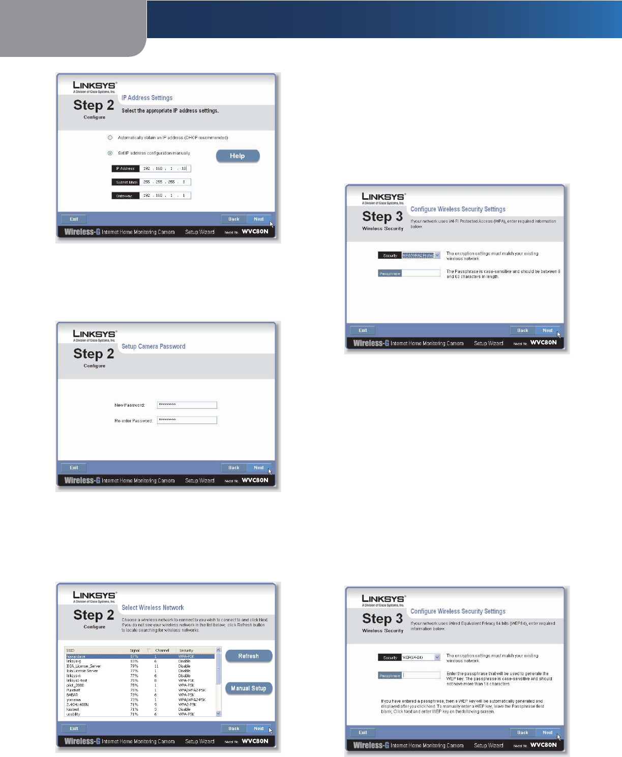
Set IP address configuration manually Select
this option if you want to manually assign a static IP
address to the Camera.
If you select this option, fill in the IP Address,Subnet
Mask, and Gateway fields.
9.
10.
•
•
Chapter 2 Setting Up and Mounting the Camera
7
Wireless-G Internet Home Monitoring Camera
Enter the Static IP Address
If you want to keep the Camera’s default password
(admin), leave the fields unchanged and click Next.
If you want to change the password, enter the new
password, re-enter to confirm, then click Next.
Enter the Camera Password
The Wizard will search for wireless networks, then list
the wireless networks found. If the wireless network
you want to connect to is not listed, click Refresh to
update the list. Select the wireless network that you
want to connect the Camera to, then click Next.
Select Wireless Network
11.
12.
The Wizard displays the wireless security method that
your network is using: WPA/WPA2-Personal,WEP
(128-Bit), or WEP (64-Bit). Follow the appropriate
instructions below. If you are not using wireless
security, select Disabled and go to step 14.
WPA/WPA2-Personal
Enter a passphrase in the
Passphrase field and click Next. The passphrase is case-
sensitive and must be from 8 to 63 characters in length.
Security Settings - WPA/WPA2-Personal
WEP (64-Bit) or WEP (128-Bit) To generate the WEP
key automatically, enter a passphrase in the Passphrase
field and click Next. The passphrase is case-sensitive and
should not be longer than 16 characters. It must match
the passphrase of your other wireless network devices
and is compatible with Linksys wireless products only.
(If you have any non-Linksys wireless products, enter
the WEP key manually on those products.)
To manually enter a WEP key, leave the Passphrase field
blank, click Next, and enter the WEP key on the next
screen. This WEP key must match the WEP key of your
wireless network. For 64-bit WEP encryption, enter
exactly 10 hexadecimal characters. For 128-bit WEP
encryption, enter exactly 26 hexadecimal characters.
Valid hexadecimal characters are “0” to “9” and “A” to “F”.
After you have entered the WEP key, click Next.
Security Settings - WEP (64-Bit) or WEP (128-Bit)
13.
•
•
Chapter 2 Setting Up and Mounting the Camera
8
Wireless-G Internet Home Monitoring Camera
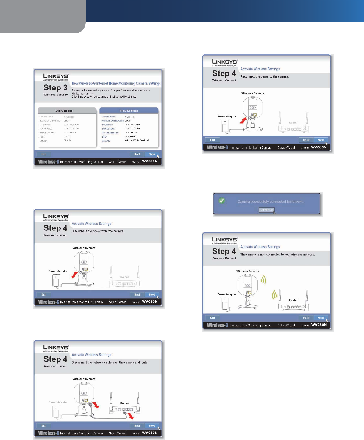
Review the Camera’s settings. To make changes to the
settings, click Back to go back to the previous screen.
If the settings are correct, click Save to continue.
Save the Camera Settings
When the Wizard informs you that the new Camera
settings have been saved, click Continue.
Disconnect the power from the camera. Click Next.
Disconnect the Power
Disconnect the network cable from the Camera and
from your switch or router. Click Next.
Disconnect the Network Cable
14.
15.
16.
17.
Reconnect the power to the Camera. Click Next.
Reconnect the Power
The Setup Wizard displays Camera successfully
connected to network. Click Continue, then click
Next on the following screen.
Camera Successfully Connected to Network
Camera Connected to Wireless Network
The Congratulations screen appears.
Install Camera Utility Click this to install the Camera’s
Utility.
Online Registration Click this to register your Camera
online.
Exit Click this to exit the Setup Wizard and install the
Camera’s utility later.
Go to the “Placement Options” section.
18.
19.
20.
•
•
•
Chapter 2 Setting Up and Mounting the Camera
9
Wireless-G Internet Home Monitoring Camera
Placement Options
The Camera can stand on a surface or be mounted on a
wall. Depending on the positioning you want, you attach
the Camera head to its stand at two different points.
Stand Option
Follow these steps to stand the Camera on a surface.
Insert the screw end of the stand into the hole on the
bottom panel.
Tighten the screw and then the thumbscrew.
Place the Camera, and adjust the tilt of its head
accordingly, as described below in section “Camera
Head Tilting”.
Thumbscrew
(tightened)
Camera in Standing Position
Wall Mount Option
You use the Camera’s stand to mount the Camera on a
wall. The stand has two wall-mount slots that are spaced
58 mm (2.28 inches) apart.
Insert the screw end of the stand into the hole on the
back panel.
Tighten the screw end and then the thumbscrew.
Determine where you want to mount the Camera.
Attach two screws to the wall, so that the Camera’s
wall-mount slots line up with the two screws.
Maneuver the Camera so the screws are inserted into
the two slots.
1.
2.
3.
1.
2.
3.
4.
Adjust the tilt of its head accordingly, as described
below in section “Camera Head Tilting”.
Hole for Attaching Stand
(Wall-Mount Option)
Wall Mount Option
Camera in Wall-Mounting Position (side view)
58 mm
(2.28 inches)
Wall-Mount Slots
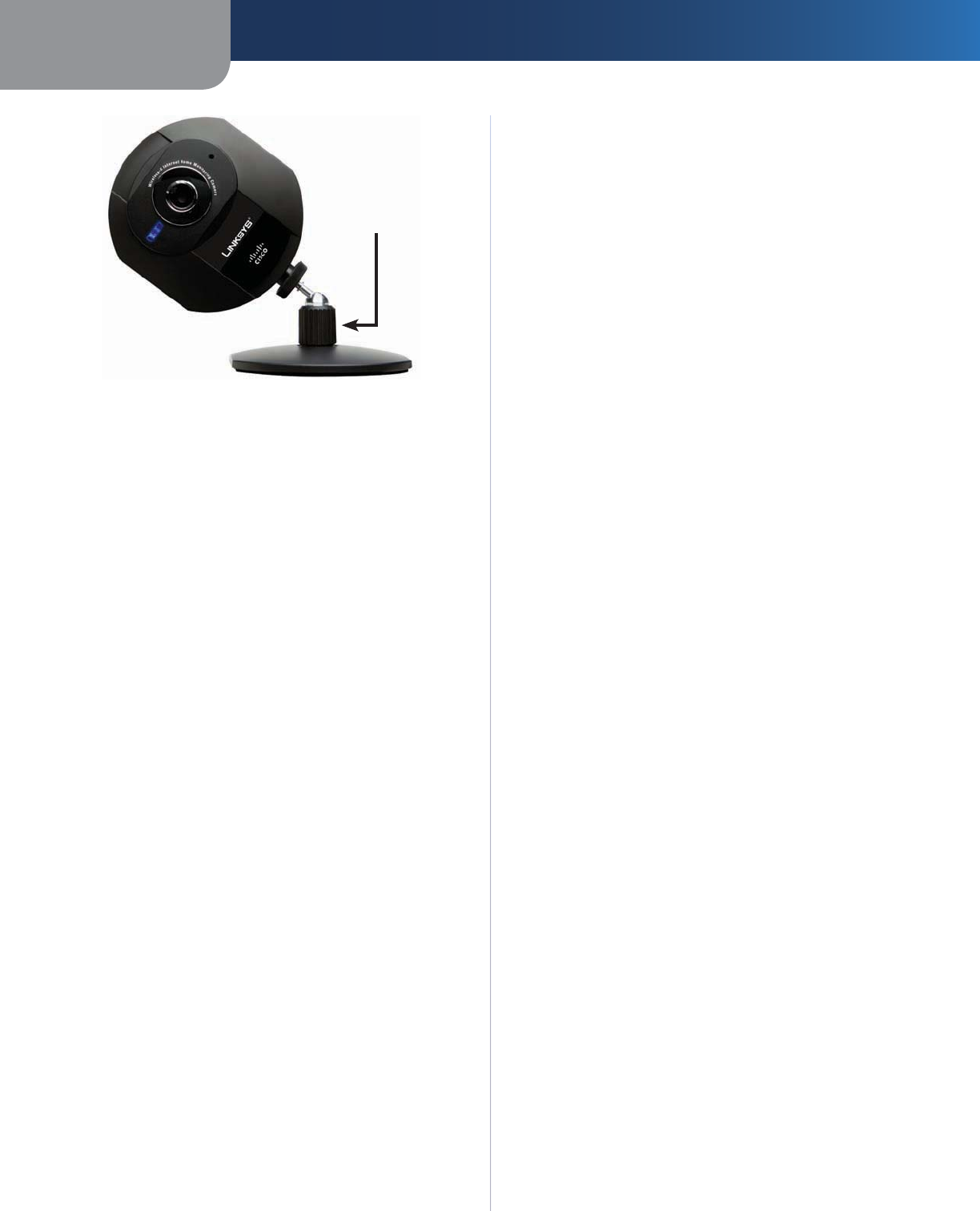
Camera Head Tilting
After the Camera is assembled, you can tilt the Camera
head on its ball joint using the lock nut on the camera
stand. Loosen the lock nut, tilt the camera head as desired,
then tighten the lock nut to secure the position.
5.
Chapter 2 Setting Up and Mounting the Camera
10
Wireless-G Internet Home Monitoring Camera
Lock Nut
Camera Tilting Feature with Stand Option
The installation of the Wireless-G Internet Home
Monitoring Camera is complete. Go to “Chapter 3:
Installing and Using the Camera Utility.”
For information about advanced configuration using
the Camera’s Web-based Utility, go to “Chapter 4:
Advanced Configuration with the Web-Based Utility.”
Chapter 3 Installing and Using the Camera Utility
11
Wireless-G Internet Home Monitoring Camera
Chapter 3:
Installing and Using the
Camera Utility
Overview
This chapter will instruct you on how to install and use the
Camera Utility on your PC. The Utility allows you to easily
view and record the Camera’s video.
If another Wireless-B or Wireless-G Internet Camera Utility
is already installed on your PC, Linksys recommends that
you uninstall it before installing this Camera Utility.
NOTE: To view video using a web browser, you
must use Internet Explorer version 5.5 or higher.
The View Video feature will not work with
other web browsers. If you do not use Internet
Explorer v5.5, use the Camera Utility instead.
Installing the Camera Utility
On the Welcome or Congratulations screen of the Setup
Wizard, click Install Camera Utility.
Install Camera Utility Screen
The Setup Wizard begins to install the Camera Utility.
The progress of the installation is displayed.
When the Setup Wizard informs you that the
installation is complete, click Continue. The Utility will
automatically start up and display the Setup screen.
Camera Utility Installation Completed
Go to the “Using the Camera Utility for the First Time”
section.
1.
2.
3.
Using the Camera Utility for the First Time
The Camera Utility starts up automatically after the Utility
is successfully installed. This section describes the steps to
follow to set up the Camera.
The Camera Utility displays the Setup screen and
searches for your Wireless-G Camera.
Setup Screen - Searching for Camera
When the Authorization screen appears, enter your
User Name and Password:
User Name Enter admin in this field.
Password If you did NOT change the password
in Step 11 of section “Setup Wizard” in “Chapter 2:
Setting Up and Mounting the Camera,” enter admin
in this field. Otherwise, enter the new password.
Authorization Screen
Click Save, then Yes to save the Camera’s settings.
To learn how to use the Camera Utility, go to “Using
the Camera Utility.”
Advanced users: If you want to use the Camera’s Web-
based Utility, go to “Chapter 4: Advanced Configuration
with the Web-Based Utility.”
1.
2.
•
•
3.
Chapter 3 Installing and Using the Camera Utility
12
Wireless-G Internet Home Monitoring Camera
Using the Camera Utility
After the Camera Utility is installed, its icon is displayed on
the Desktop and in the System Tray of the Taskbar. To open
the Camera Utility, use either icon as follows:
Double-click the icon on your desktop
Right-click the icon in the system tray, then click
Wireless-G Internet Home Monitoring Camera.
Desktop Icon System Tray Icon
When you are finished using the Camera Utility, exit the
Utility as follows:
Close each open Utility window by clicking Exit or by
clicking the X button in the upper-right corner.
Right-click the Utility’s system tray icon and select Exit.
Monitor Window
After you open the Utility, the Monitor window is displayed.
The Monitor window contains the following sections:
Camera Status, Motion Detection Events, Hard Disk Quota,
the viewing area containing video displays for Channels
1-9, video layout controls, and video control buttons.
Monitor Window
To display the Setup window, click Setup. To display the
Playback window, click Playback. To get help information,
click Help.
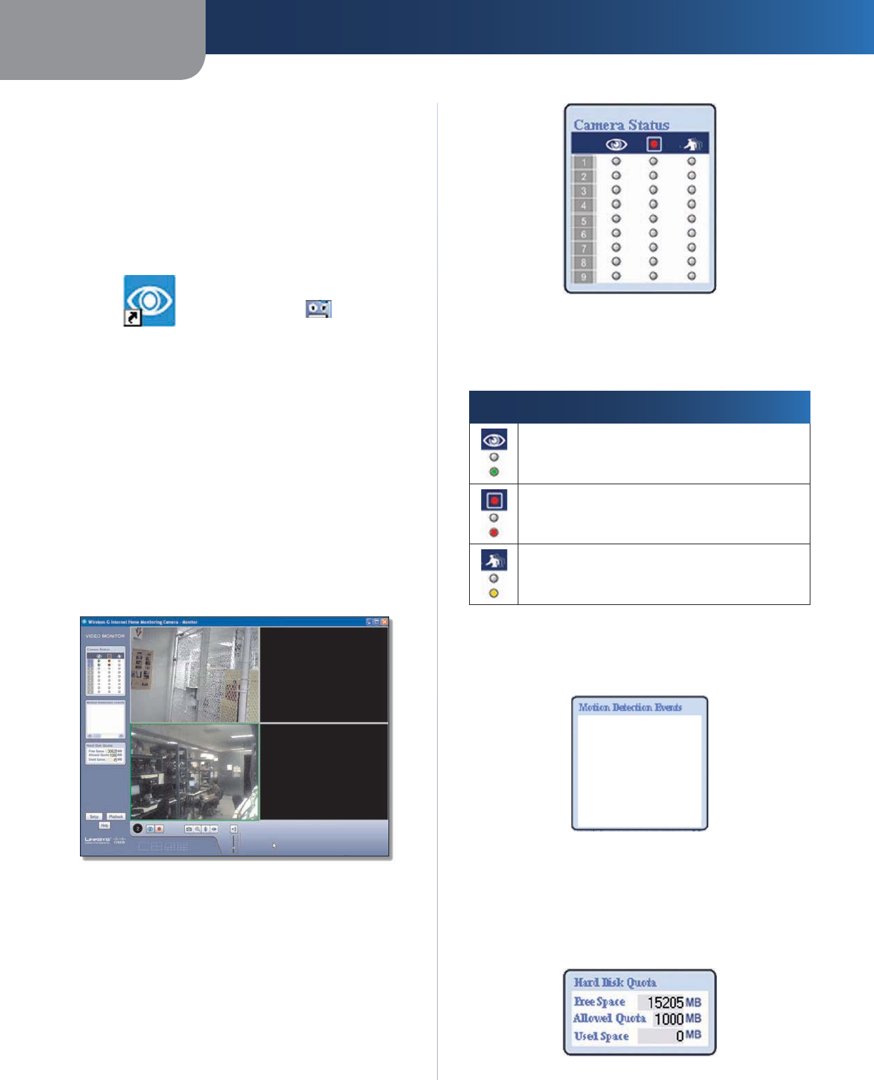
Camera Status
This section of the Monitor window provides the following
status information for all the Cameras the Utility has
detected: Camera is being viewed, Camera is being
recorded, motion detection is enabled on the Camera:
•
•
•
•
Camera Status
A blue channel number (1-9) means a Camera has been
detected on that channel. Each Camera’s status is given by
colored indicators as described in the following table.
Icon Status Indications
Viewing Status:
Clear - Camera’s video is not being viewed.
Green - Camera’s video is being viewed.
Recording Status:
Clear - Camera’s video is not being recorded.
Red - Camera’s video is being recorded.
Motion Detection Status:
Clear - Camera’s motion detection is disabled.
Yellow - Camera’s motion detection is enabled.
Motion Detection Events
If motion detection is enabled, this section of the Monitor
window lists the most recent motion detection events.
Motion Detection Events
Hard Disk Quota
This section of the Monitor window lists information
related to the amount of hard disk that is allocated for
recorded video.
Hard Disk Quota
Chapter 3Installing and Using the Camera Utility
13
Wireless-G Internet Home Monitoring Camera
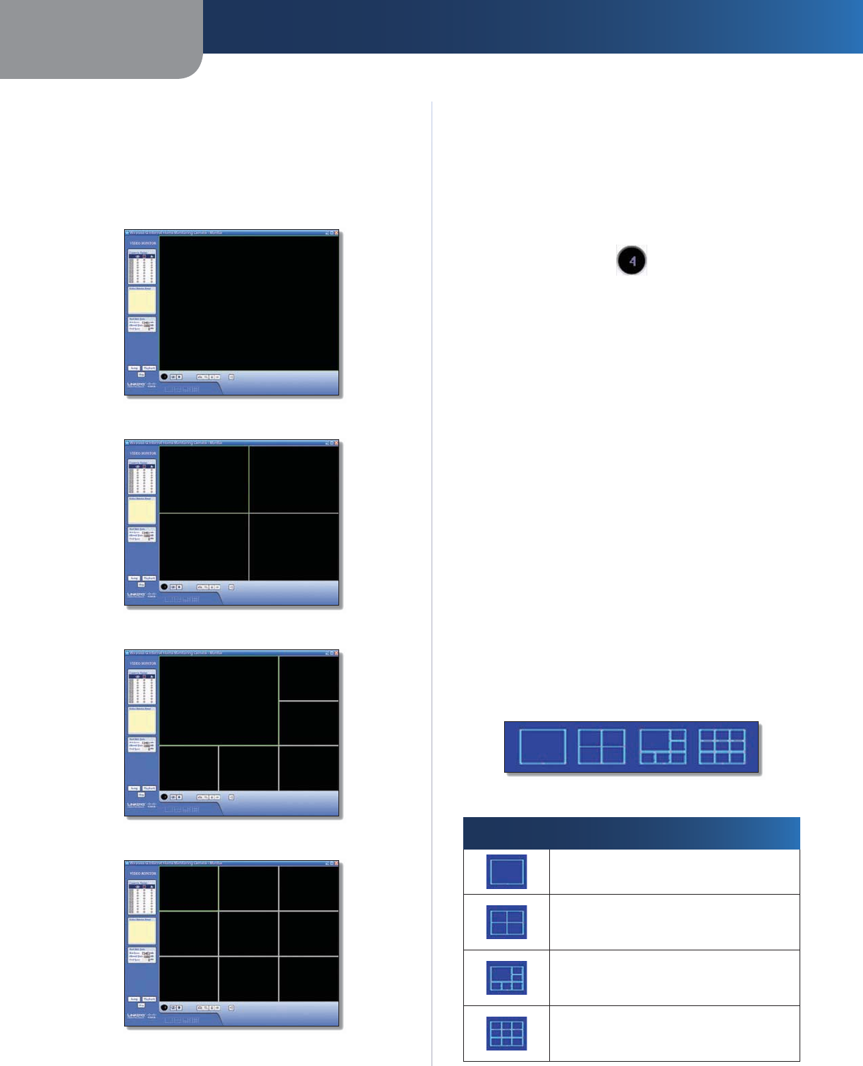
Viewing Area
The Viewing Area takes up most of the Monitor window.
The Viewing Area can have four different layouts, with
video windows for one, four, six, or nine Cameras. The
layout is selected using the video layout controls described
in “Video Layout Controls’”.
Viewing Area - Single-Camera Display
Viewing Area - Four-Camera Display
Viewing Area - Six-Camera Display
Viewing Area - Nine-Camera Display
Multiple-Camera Layouts
In a multiple-Camera layout, one of the video windows
is always outlined in green. This indicates the currently
selected Camera. The Video Control buttons can be used
to perform various functions on the video from this
Camera. For information on the video control buttons,
refer to “Video Control Buttons” below.
Channel Number of Selected Camera
The channel number of the selected Camera is indicated
below the lower left corner of the Viewing Area. To specify
a different Camera as the selected Camera, click on that
Camera’s video window.
Each Camera can be displayed using any of the video
windows in the layout. To move a Camera from one video
window to another, click and drag the Camera’s video
window to another video window. The two Cameras
originally assigned to each of the two windows will then
swap places. This is especially useful for the six-Camera
layout, which has one large video window and five smaller
ones. A Camera assigned to one of the smaller windows
can be quickly enlarged by dragging it to the large
window.
To quickly view any Camera’s video at full scale, double-
click that Camera’s video window. The layout will change
to a single-camera display of the selected Camera’s video.
Video Layout Controls
This section of the Monitor window lets you change the
layout of the viewing area. To select a particular layout,
click the layout’s icon.
Video Layout Icons
Icon Function
Click this icon to display video from one
Camera only.
Click this icon to display video from up to
four Cameras. The video windows are all
of equal size.
Click this icon to display video from up
to six Cameras, with one large video
window and five small video windows.
Click this icon to display video from up to
nine Cameras. The video windows are all
of equal size.
Chapter 3Installing and Using the Camera Utility
14
Wireless-G Internet Home Monitoring Camera
Video Control Buttons
The video control buttons are located along the lower
left edge of the viewing area. These buttons act upon the
selected Camera as explained below.
Button Function
View Click this button to view the
current video.
Record Click this button to record* the
current video.
Snapshot
Click this button to take a
snapshot of the
current video image
.
Zoom Click this button to zoom into
current video display. The zoom factor
cycles through 1x, 2x, and 4x.
Flip Click this button to flip the current
video display top-to-bottom.
Mirror Click this button to reverse the
current video display left-to-right.
Sound Click this button to toggle the
sound on or off.
Volume Slide this bar upward to increase
the volume. Slide the bar downward to
decrease the volume.
* During recording, the Utility’s System Tray icon turns
into an animated icon (arrow moves up and down). When
recording ends, the icon reverts to its original state.
Recording In Progress No Recording In Progress
Playback Window
The Playback window is used to play back videos that you
have recorded and saved.
Playback Screen
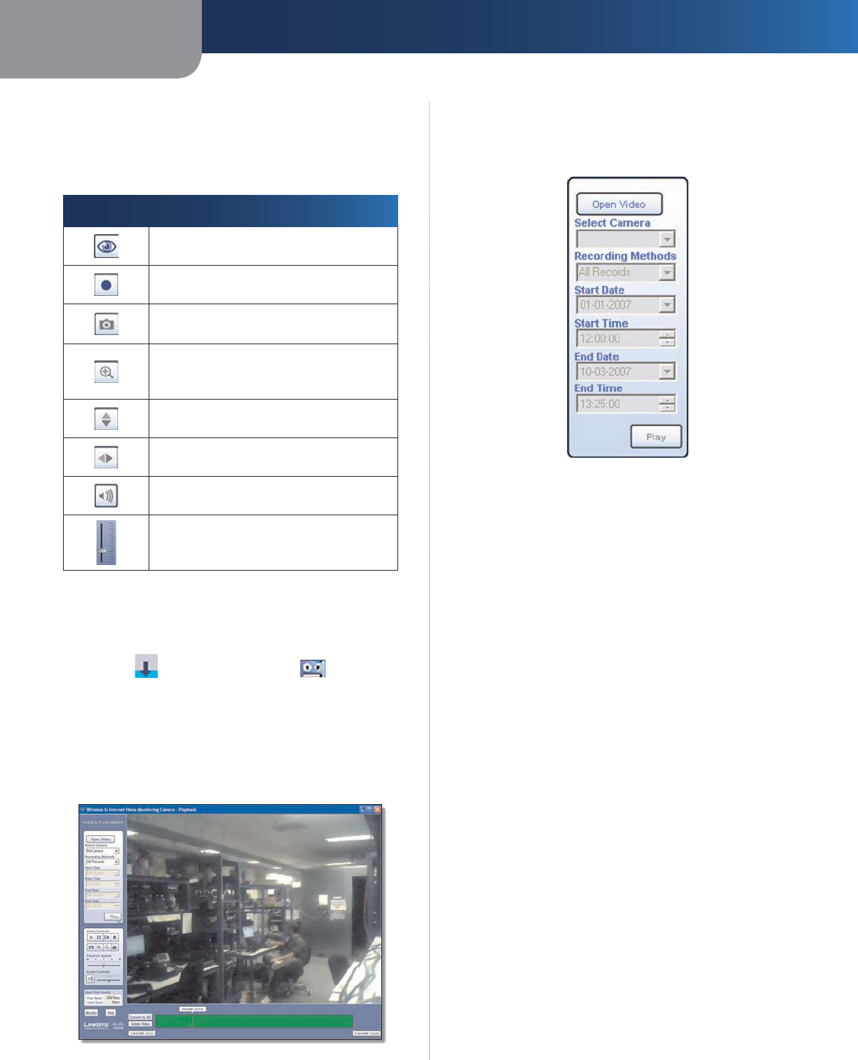
Video Selection
This section of the Playback window lets you select the
video(s) for playback.
Playback Selection
Open Video Click this button if you want to select the
folder containing the videos on your computer. Otherwise,
use the remaining fields to select the video from the
default recording folder (indicated by the Recording Path
field of the Setup > Preferences screen).
Select Camera Select the Camera that recorded the
video.
Recording Methods Specify the criteria to be used to
select the video for the selected Camera:
All Records Displays all recorded videos for the
selected Camera.
Select Period Limits the video selections to the range
defined by Start Date/Time and End Date/Time.
Motion Detection Limits the selections to videos that
were recorded as a result of motion detection.
If the Recording Methods field is set to Select Period,
define the date and time period by filling in the following
fields.
Start Date Specify the starting date in mm-dd-yyyy
format.
Start Time Specify the starting time in hh:mm:ss
format.
End Date Specify the ending date in mm-dd-yyyy
format.
End Time Specify the ending time in hh:mm:ss
format.
Play Click this button to begin playing the selected
videos.
•
•
•
•
•
•
•
Chapter 3Installing and Using the Camera Utility
15
Wireless-G Internet Home Monitoring Camera
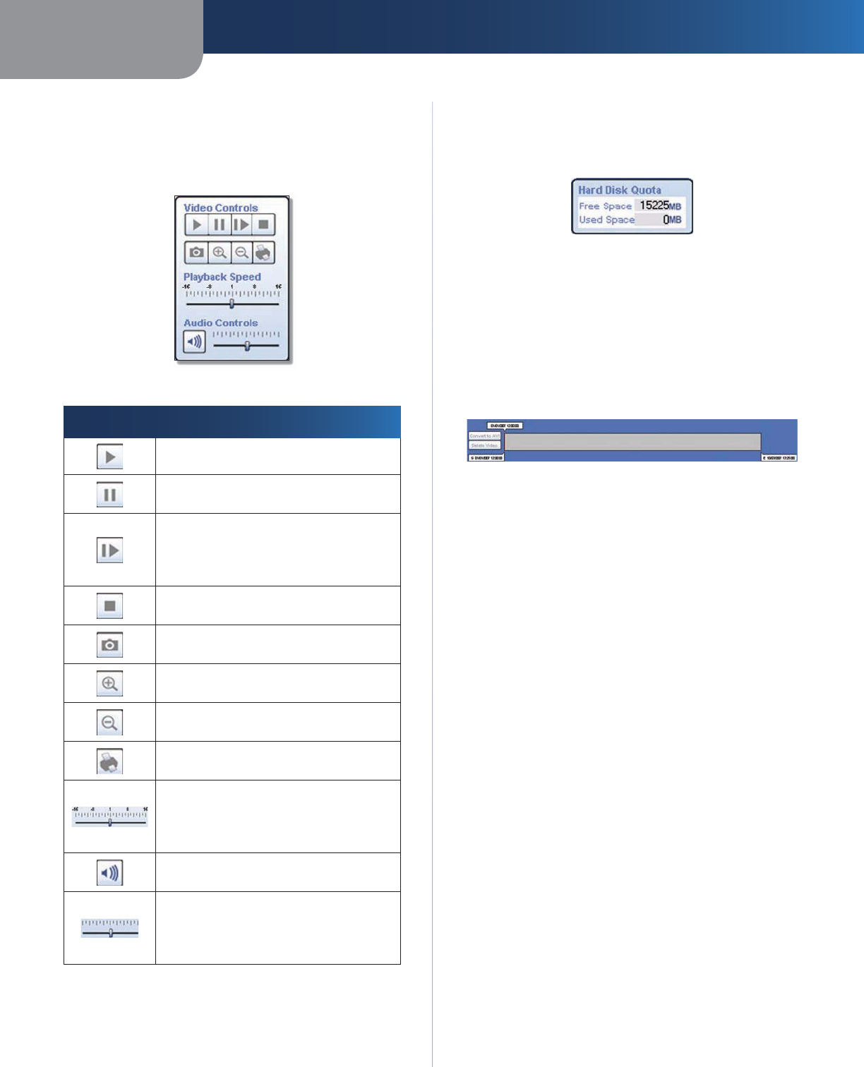
Basic Video Controls
This section of the Playback window lets you perform basic
functions on the video(s) you have selected for playback.
The controls and their functions are described below.
Basic Video Controls
Control Function
Play Click this button to play the video.
Pause Click this button to pause the
video.
Frame by Frame Click this button
to play exactly one video frame. Each
successive click advances playback
exactly one frame.
Stop Click this button to stop video
playback.
Snapshot Click this button to capture a
still image of the current video display.
Zoom In Click this button to zoom in
on the video display.
Zoom Out Click this button to zoom
out of the video display.
Print Click this button to print the
current video image.
Playback Speed Slide this bar to adjust
the playback speed. Slide it to the left
for slower playback or to the right for
faster playback.
Sound Click this button to turn the
sound on or off.
Volume Slide this bar to adjust the
sound volume. Slide it to the left to
lower the volume or to the right to raise
the volume.
Hard Disk Quota
This section of the Playback window indicates how much
hard disk is allocated for recorded video.
Hard Disk Quota
Advanced Video Controls
Advanced video functions are performed using the
advanced video controls. These controls are located
below the viewing area and consist of two buttons and
three markers. Each marker displays the date and time of
a specific point in the video. If you reposition a marker, the
displayed date and time will change accordingly.
Video Controls
Convert to AVI To convert the currently playing video to
AVI format, click this button, select a destination folder for
the AVI file, and then click OK.
Delete Video Click this button to delete the video from
your computer.
<mm/dd/yyyy hh:mm:ss> This marker displays the date
and time of the current point in the video. As playback
proceeds, this marker moves to the right. To immediately
move to another point in the video, slide this marker to
the desired point.
S <mm/dd/yyyy hh:mm:ss> This marker is used to select
the starting point for playback. By default this marker is
always set to the start of the video. If you want to start
playback at a later point in the video, move this marker to
the right.
E <mm/dd/yyyy hh:mm:ss> This marker is used to select
the ending point for playback. By default this marker is
always set to the end of the video. If you want to stop
playback at an earlier point in the video, move this marker
to the left.
Other Buttons
Click Monitor to open the Monitor window. Click Help to
display help information.
Chapter 3Installing and Using the Camera Utility
16
Wireless-G Internet Home Monitoring Camera
Setup Screen
The Setup screen is accessed by clicking the Setup button
on the Monitor window of the Camera Utility. There are
four tabs along the left side of the Setup screen: Network
Camera, Internet Camera, Recording Schedule, and
Preferences. By default, the Network Camera tab is
selected when the Setup screen is opened. These tabs
display screens whose functions are described below.
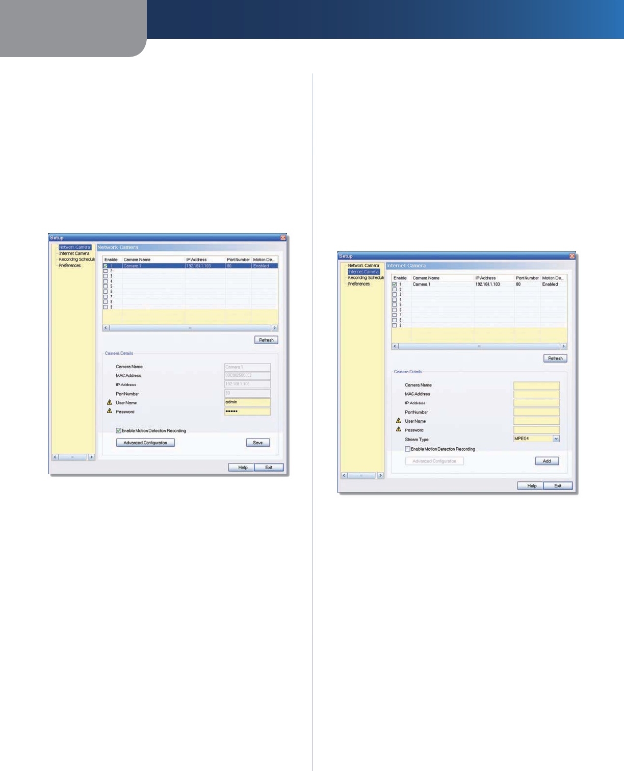
Setup > Network Camera
Click the Network Camera tab to set up a network Camera.
Setup > Network Camera
The upper section of the Setup > Network Camera screen
contains a list of all Wireless-G Cameras that have been
detected (up to 9). The Camera Details section of the
screen provides information about the selected Camera.
Camera List
Enable Check this box to enable the Camera. Uncheck
the box to disable the Camera.
Camera Name Displays the name of the Camera.
IP Address Displays the Camera’s IP address.
Port Number Displays the Camera’s port number.
Motion Detection Recording Indicates if motion
detection recording is enabled or disabled.
Camera Details
Camera Name Displays the name of the Camera that you
specified while running the Setup Wizard.
MAC Address
Displays the Camera’s MAC address.
IP Address Displays the Camera’s IP address.
Port Number Displays the Camera’s port number.
User Name and Password Displays the user name. The
password is displayed as “•••••“ for security reasons.
Enable Motion Detection To enable motion detection
recording, check this checkbox. The default is disabled.
Click
Advanced Configuration
to open the Web-based Utility.
Click Save to save your changes, or click Exit to exit without
saving changes. Click Help to display help information.
Setup > Internet Camera
To set up a Camera located on the Internet, click the
Internet Camera tab, then fill in the fields and click Add.
Setup > Internet Camera
Camera Name Enter the name assigned to the Camera.
MAC Address Enter
the Camera’s MAC address.
IP Address Enter the Camera’s IP address.
Port Number Enter the Camera’s port number.
User Name and Password Enter the Camera’s user name
and password.
Stream Type Select either MJPEG or MPEG4 (default).
Enable Motion Detection Recording
Check the box to
enable motion detection recording. The default is disabled.
Add After you have entered all of the information for the
Camera, click this button to add the Camera to the list.
Advanced Configuration Click this button to open the
Web-based Utility in your web browser.
Click Advanced Configuration to open the Web-based
Utility. Click Exit to exit without saving your changes. Click
Help to display help information.
Chapter 3Installing and Using the Camera Utility
17
Wireless-G Internet Home Monitoring Camera
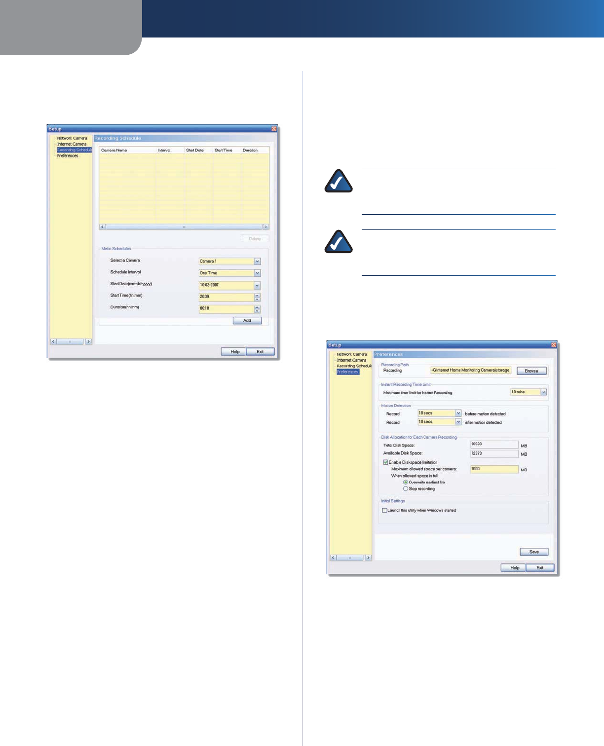
Setup > Recording Schedule
To set up a recording schedule for a Camera, then click the
Recording Schedule tab.
Setup > Recording Schedule
To schedule a recording for a Camera, follow these steps.
Fill in the following fields.
Select a Camera Select the Camera that will be
recorded from the drop-down menu.
Schedule Interval Select the days on which you
want the Camera to record. The choices are One
Time, Every Day, Mon-Fri, Sat-Sun, Sun, Mon, Tue,
Wed, Thu, Fri, and Sat. (All settings except One Time
cause recording to occur on a recurring basis.)
Start Date (mm-dd-yyyy) Enter the date to start
the recording, in mm-dd-yyyy format.
Start Time (hh:mm) Enter the time to start the
recording, in hh:mm format.
Duration (hh:mm) Enter the duration of the
recording in hh:mm format.
Click Add to save the new scheduled recording
information.
The scheduled recording will appear in the list of
scheduled recordings at the top of the screen.
To delete a scheduled recording, select the recording from
the list, and click Delete.
Click Help to display help information. Click Exit to exit
without saving your changes.
1.
•
•
•
•
•
2.
3.
Memory Requirements for Video Recordings
You may find it helpful to know how much memory is
required to hold a video recording. For information on
estimated bit rates for a typical video recording at each
available resolution and video, refer to the “Setup > Image”
section of “Chapter 4: Advanced Configuration with the
Web-Based Utility.”
NOTE: In order for the scheduled recordings to
occur, the Camera Utility must be running on a
networked PC.
NOTE: The maximum length of a recording file
is one hour. If a recording is more than one hour
long, then multiple files will be saved.
Setup > Preferences
To configure the Camera’s preference settings, click the
Preferences tab.
Setup > Preferences
The Setup > Preferences screen allows you to configure the
following settings.
Recording Path
Recording This is the drive and folder where recorded
video files will be saved on your computer. The default is
C:\Program Files\Wireless-G Internet Home Monitoring
Camera\storage
.

Chapter 3Installing and Using the Camera Utility
18
Wireless-G Internet Home Monitoring Camera
Instant Recording Time Limit
Maximum Time Limit for Instant Recording This is the
maximum length of a recording that is started by clicking
the Record button on the Monitor window. The default is
10 min.
Motion Detection
The following two settings apply only if the Motion
Detection Recording feature is enabled.
Record before motion detected This is the length of
time prior to the detection of motion that will be saved
with the recording. Having this additional footage can
help to show the motion more clearly when it occurs.
Record after motion detected This is the length
of time that the Camera will continue to record after
motion is detected.
Disk Allocation for Each Camera Recording
Total Disk Space This is the total amount of storage
space on your PC’s hard drive.
Available Disk Space This is the total amount of
remaining storage space on your PC’s hard drive.
Enable Diskspace Limitation If you want to limit the
amount of disk space used by each Camera, check this
box, then fill in the fields below.
Maximum allowed space per camera Enter the
maximum allowed space per camera in MB. The default
is 1000 MB.
When allowed space is full Select the action to take
when the space limit is reached, either Overwrite
earliest file (default), or Stop recording.
Initial Settings
Launch this Utility when Windows started Check this
box if you want to have this utility started automatically
whenever Windows is started.
Click Save to save any settings you have changed on the
screen, or click Exit to exit without saving your changes.
Click Help to display help information.
If you want to use the Camera’s Web-based Utility, go
to “Chapter 4: Advanced Configuration with the Web-
Based Utility.”
•
•
•
•
Chapter 4 Advanced Configuration with the Web-based Utility
19
Wireless-G Internet Home Monitoring Camera
Chapter 4:
Advanced Configuration
with the Web-based Utility
Overview
Use the Camera’s Web-based Utility to access and alter its
settings. This chapter will describe each web page in the
Utility and its features. The Utility can be accessed via the
web browser of a computer connected to the Camera.
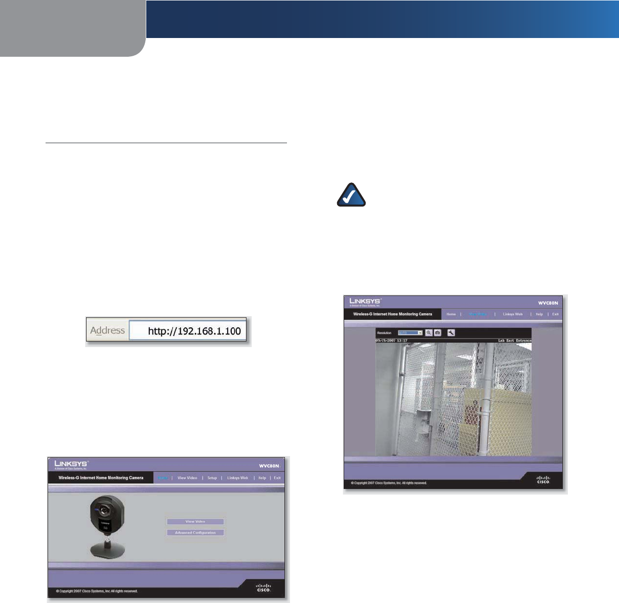
How to Access the Web-based Utility
You can access the Utility using either of these methods.
Launch Internet Explorer, and enter the Camera’s IP
address in the Address field. Then, press Enter.
Enter the Camera’s IP Address
From the Monitor window of the Camera Utility,
select the Camera, then click the Setup button. (For
instructions on how to launch the Camera Utility, refer
to “Using the Camera Utility” in “Chapter 3: Installing
and Using the Camera Utility.”
The Welcome screen of the Web-based Utility will appear.
Web-Based Utility Welcome Screen
There are six tabs across the top of the Welcome screen:
Home,View Video,Setup,Linksys Web,Help, and Exit.
Home – Select this tab to return to the Welcome
screen.
View Video – Select this tab to view the Camera’s video.
Go to the “View Video” section for more information.
Setup – Select this tab to alter the Camera’s settings.
Go to the “Setup” sections for more information.
Linksys Web – Select this tab to go to the Linksys
website, www.linksys.com.
•
•
•
•
•
•
Help – Select this tab to display the Help screen. Go to
the “Help” section for more information.
Exit – Select this tab to close the Utility.
View Video
Follow these instructions to view the Camera’s video.
Click the View Video tab on the Welcome screen.
NOTE: To view video using a web browser,
you must use Internet Explorer version 5.5 or
higher. The View Video feature will not work
with Netscape. Netscape users should use the
Camera Utility instead.
The View Video screen appears, showing the live video
from the Camera.
View Video Screen (640x480 Resolution)
The top of the View Video screen contains a number of
controls that are used to adjust the video display. These
controls and their functions are described in the sections
below.
There are four selectable tabs across the top of the View
Video screen: Home,Linksys Web,Help, and Exit.
Home – Select this tab to return to the Welcome screen,
or to edit the Camera’s settings with the Web-based
Utility (select Setup or Advanced Configuration on
the Welcome screen).
Linksys Web – Select this tab to go to the Linksys
website, www.linksys.com.
Help – Select this tab to display the Help screen. Go to
the “Help” section for more information.
Exit – Select this tab to close the Utility.
•
•
1.
2.
•
•
•
•
Chapter 4 Advanced Configuration with the Web-based Utility
20
Wireless-G Internet Home Monitoring Camera
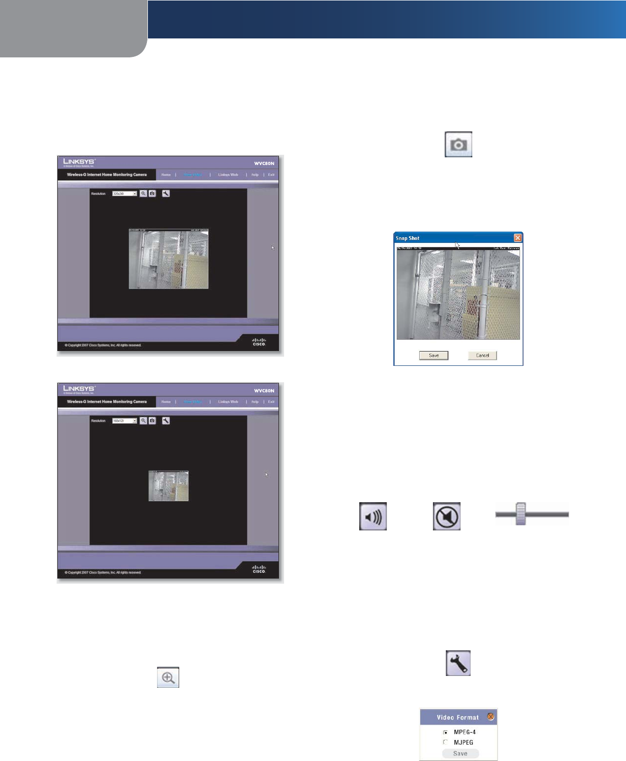
Resolution
Use the Resolution drop-down menu to select the display
resolution. Possible values are Auto (default), 640x480,
320x240, or 160x120. The display changes to the new
resolution immediately after it is selected.
View Video Screen (320x240 Resolution)
View Video Screen (160x120 Resolution)
Zoom Factor
You use the Zoom button to zoom in and out of the
displayed video.
Zoom Button
When you click the button, the cursor changes to a
magnifying glass labeled with the current zoom factor
(cycles through 1x, 2x, and 4x). Position the cursor over the
part of the image you want to magnify and click once.
Snapshot
You use the Snapshot button to capture a still image of
the video display.
Snapshot Button
When you click this button, the Snap Shot window
appears. Click Save to save the image, or click Cancel to
exit without saving the image.
Snap Shot Window
Audio
Use the Audio button to toggle the sound on or off from
the Camera’s built-in microphone. The button’s appearance
indicates whether the sound is on or off. When the sound
is on, you can adjust the volume by sliding the volume
control to the left to lower the volume, or to the right to
increase the volume.
Audio Button:
Sound ON
Audio Button:
Sound OFF
Volume Adjustment
Video Format
To s
elect the video format, click
the Video Format button,
and
the Video Format window appears. Select either
MPEG-4 or MJPEG, then click Save. To exit without saving,
click the X in the upper-right corner of the window.
Video Format Button
Video Format Window
Chapter 4 Advanced Configuration with the Web-based Utility
21
Wireless-G Internet Home Monitoring Camera
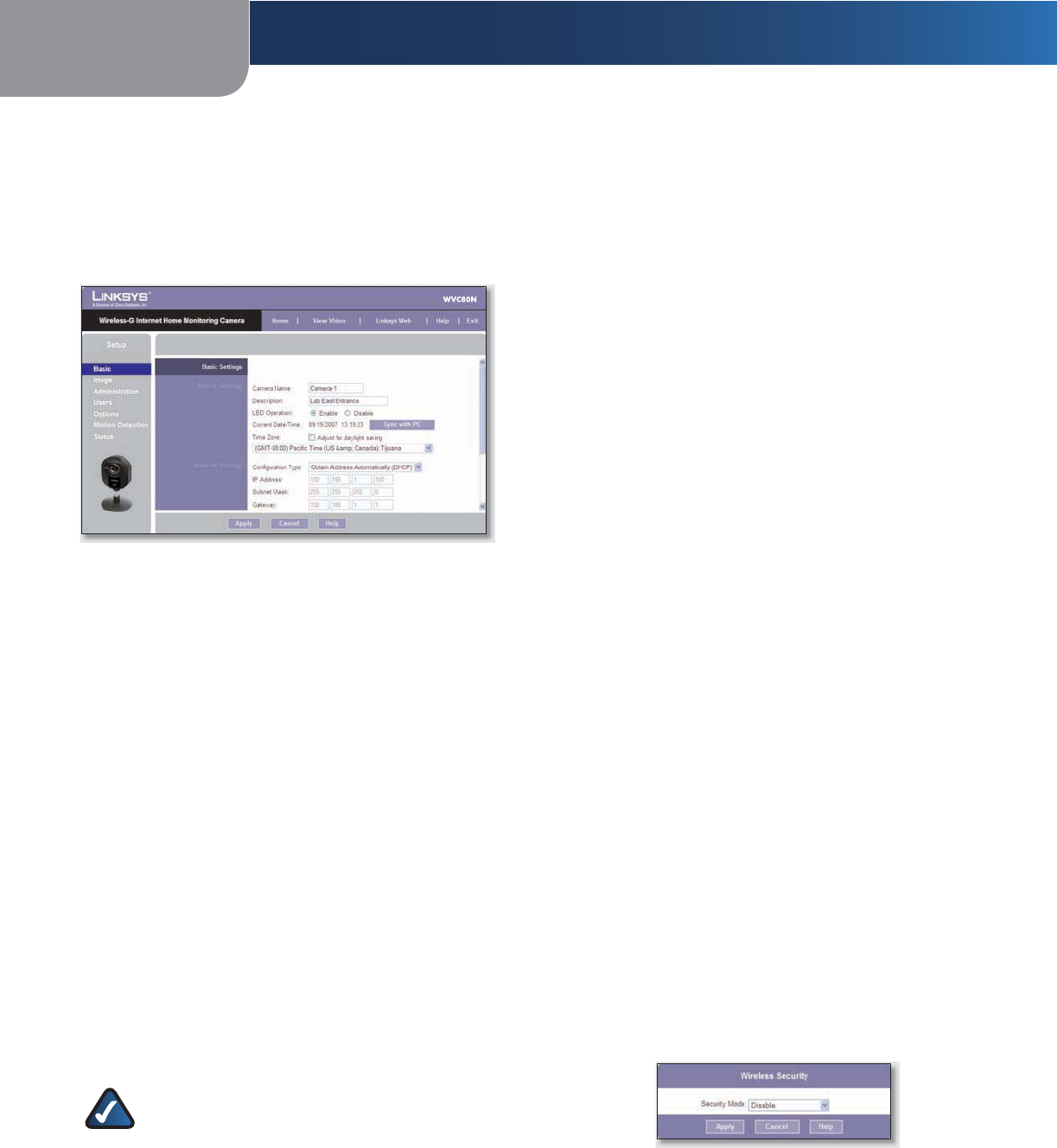
Setup > Basic
The Setup > Basic screen appears when you click the Setup
tab or Advanced Configuration on the Welcome screen.
The Setup > Basic screen allows you to alter the Camera’s
Device settings, Network settings, Wireless settings, and
Security settings.
Setup > Basic Screen
Edit the settings on this screen as needed. Then, to save
your changes, click Apply. To cancel any unsaved changes,
click Cancel. To get additional information about the
screen’s features, click Help.
Device Settings
Camera Name You may assign the Camera any name
up to 15 characters long. Unique, memorable names
are helpful, especially if you use multiple Cameras on
the same wireless network.
Description Enter information about the Camera in
this field. You can enter up to 32 characters.
LED Operation This feature allows you to enable or
disable the Camera’s LED.
Current Date/Time This displays the Camera’s current
date and time. If it is incorrect, click Sync with PC to
use your computer’s date and time.
Time Zone Select the time zone for the Camera’s
location.
Adjust for Daylight Saving Time Select this to adjust
the Camera’s current time for Daylight Saving Time.
NOTE: You must unselect this option when
Daylight Saving Time finishes.
•
•
•
•
•
•
Network Settings
Configuration Type If you want to automatically
assign the Camera an IP address from a DHCP server,
then select Obtain Address Automatically (DHCP)
(default). If you want to assign the Camera a static IP
address, then select Fixed IP Address, and complete
the IP Address, Subnet Mask,Gateway,Primary DNS and
Secondary DNS fields.
IP Address, Subnet Mask, Gateway, Primary DNS,
Secondary DNS Complete these fields if you want
to assign the Camera a static IP address. You need to
enter at least one DNS address.
Wireless Settings
SSID Enter the network’s SSID or network name here.
Network Type Select the network’s mode, Ad-hoc or
Infrastructure.
Channel No If the Camera is set to Ad-hoc mode,
select its channel setting from the drop-down menu.
Security Click Edit Security Settings to display the
Wireless Security screen.
Setup > Basic > Wireless Security
The Wireless Security screen is used to configure the
Camera’s wireless security settings to match your wireless
network settings. The settings are as follows.
Security Mode Select the wireless security mode used
by your wireless network:
Disable (no wireless security)
WEP
WPA/WPA2 Personal.
The method selected determines which other fields are
displayed on the screen. The different security modes
and the fields that accompany them are described in
detail below.
Disable
This option implements no security on your wireless
network. Data is not encrypted before transmission.
Wireless Security - Disable Security Mode
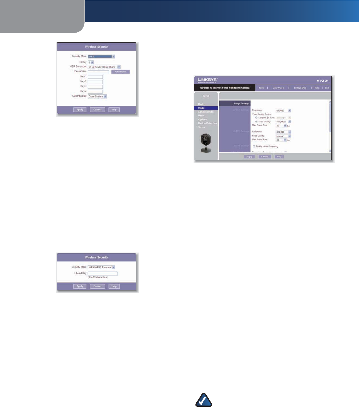
WEP
WEP is a basic encryption method, which is not as
secure as later methods such as WPA-Personal or WPA2
Personal. However, it is supported by all clients.
•
•
•
•
•
•
•
•
•
•
•
Chapter 4 Advanced Configuration with the Web-based Utility
22
Wireless-G Internet Home Monitoring Camera
Wireless Security - WEP Security Mode
TX Key Select the number of the key used on the
wireless network.
WEP Encryption Select the appropriate option
for key length based on your network settings.
Passphrase Type in the passphrase used to
generate WEP keys on your network and click
Generate.
Key 1 - Key 4 Key values can be entered manually
or generated from a passphrase.
Authentication Select the appropriate
authentication type used on the wireless network.
WPA/WPA2 Personal
This method offers TKIP encryption with dynamic
encryption keys.
Wireless Security - WPA/WPA2 Personal Security Mode
Shared Key Enter the shared key of 8 to 63
characters that will be used to access the wireless
network.
When you are finished editing the Camera’s wireless
security settings, click Apply to save your changes and
return to the Setup > Basic screen. Click Cancel at any
time to cancel any unsaved changes and return to the
Setup > Basic screen. To get additional information about
the screen’s features, click Help.
•
•
•
•
•
•
•
Setup > Image
The Setup > Image screen allows you to alter the Camera’s
video settings.
Setup > Image Screen
MPEG4 Settings
Resolution Set the resolution for viewing and recording
the Camera’s video: 640x480 (high resolution) 320x240
(medium resolution), or 160x120 (low resolution).
Video Quality Control Select either Constant Bit Rate
or Fixed Quality for the video stream.
Constant Bit Rate Select the bit rate you want for
viewing or recording the Camera’s video. The range
varies from 64 Kbps to 1.2 Mbps.
Fixed Quality Select the level of quality you want for
viewing or recording the Camera’s video. The range
varies from Very Low to Very High.
Max Frame Rate Select the maximum frame rate for the
camera. Reducing this lowers the amount of bandwidth
required by the camera. The range is from 1 to 30.
MJPEG Settings
Resolution Set the resolution for viewing and recording
the Camera’s video: 640x480 (high resolution) 320x240
(medium resolution), or 160x120 (low resolution).
Fixed Quality Select the level of quality you want for
viewing or recording the Camera’s video. The range varies
from Very Low to Very High.
Max Frame Rate Select the maximum frame rate for the
camera. Reducing this lowers the amount of bandwidth
required by the camera. The range is from 1 to 30.
NOTE: Video quality and/or performance may
be affected by the number of users connected
to the Camera.
It may be helpful to know the bit rates for video viewing or
recording at different resolutions and image quality levels.
The following table lists these estimated bit rates.
•
•
Chapter 4 Advanced Configuration with the Web-based Utility
23
Wireless-G Internet Home Monitoring Camera
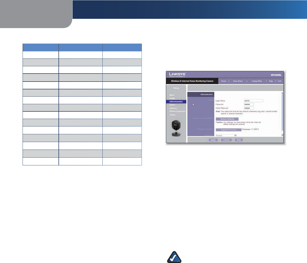
Estimated Bit Rates for Video Viewing or Recording
Resolution Quality Level Bit Rate in kbps
640 x 480 Very High 4000
640 x 480 High 3200
640 x 480 Normal 1200
640 x 480 Low 480
640 x 480 Very Low 160
320 x 240 Very High 1000
320 x 240 High 800
320 x 240 Normal 300
320 x 240 Low 120
320 x 240 Very Low 40
160 x 128 Very High 800
160 x 128 High 400
160 x 128 Normal 200
160 x 128 Low 100
160 x 128 Very Low 40
Mobile Settings
Enable Mobile Streaming Select this option to enable
video streaming to a mobile device.
Video Adjustments
Power Line Frequency Select the power line frequency
(50Hz or 60Hz) used in your region, to improve the picture
quality under fluorescent lighting.
White Balance Select the desired option to match the
current environment and lighting.
Brightness If necessary, you can adjust the brightness to
obtain a better image. For example, if the camera is facing
a bright light, the image may be too dark. In this case, you
can increase the brightness. You can select a Brightness
value between -3 and 3.
Sharpness Select the desired option for the sharpness.
You can select a Sharpness value between -3 and 3.
Options
Enable Microphone Select this to enable audio.
Using
Audio increases the bandwidth requirements slightly.
Enable Time Stamp Select this to display a time stamp
on the video.
Enable Text Display To display text on the video, select
this, then enter up to 20 characters in the field.
To save your changes, click Apply. To cancel any unsaved
changes, click Cancel. To get additional information about
the screen’s features, click Help.
Setup > Administration
The Setup > Administration screen allows you to change
the Camera’s login name and password, reset the factory
defaults, upgrade the firmware, and set the language.
Setup > Administration Screen
Login
These fields are used to change the login name and
password used to access the Camera. For security purposes,
you should change these from the default values (both set
to admin).
Login Name Enter the login name for the Camera.
Password Enter the password for the Camera.
Verify Password Re-enter the password to verify.
Restore Factory Defaults
Restore Defaults To restore the Camera to its factory
default settings, click Restore Defaults.
NOTE: This will overwrite the Camera’s settings
with the factory defaults.
Any changes you
made to the Camera’s settings will be lost; you
will not be able to recover them.
Firmware Upgrade
Upgrade Firmware New firmware versions are posted at
www.linksys.com and can be downloaded for free. If the
Camera is functioning satisfactorily, there is no need to
download a newer firmware version, unless that version
has a new feature that you want to use. Loading new
firmware onto the Camera does not always enhance its
performance.
Linksys recommends that you upgrade the Camera’s
firmware within your network; in other words, use a
computer within the Camera’s local network. If you
attempt to upgrade the Camera’s firmware from a remote
location—using a computer outside of the Camera’s local
network—the upgrade will fail.
Chapter 4 Advanced Configuration with the Web-based Utility
24
Wireless-G Internet Home Monitoring Camera
To upgrade the firmware:
Go to the Linksys website, www.linksys.com, and
download the firmware upgrade file for the Camera.
Then extract the file.
From the Setup > Administration screen, click Upgrade
Firmware.
You will see the Upgrade Firmware screen. Click Browse
to find the extracted file, and then double-click it.
Click Start Upgrade, and follow the on-screen
instructions. To cancel the upgrade, click Cancel.
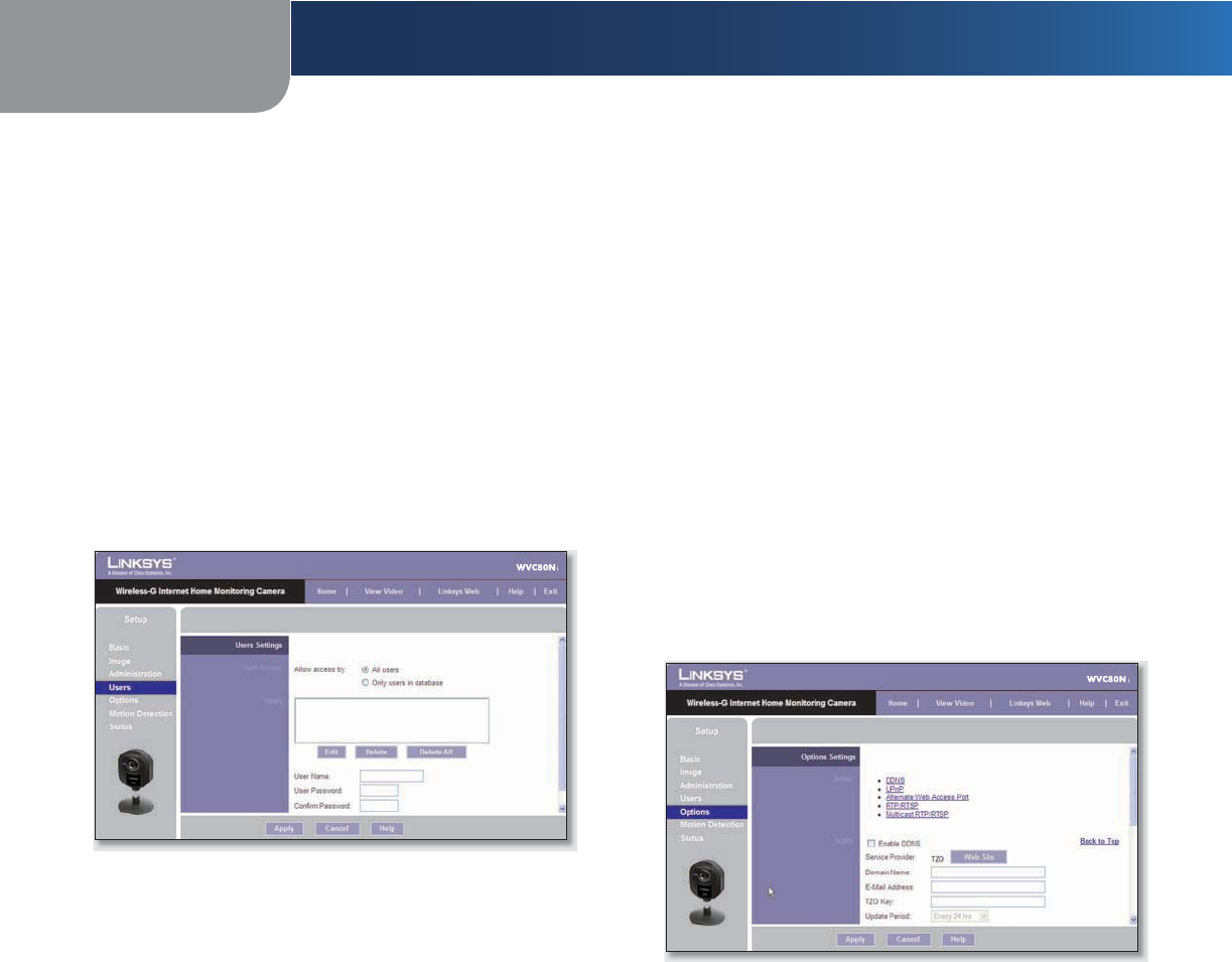
Setup > Users
The Setup > Users screen lets you designate access rights
for the Camera’s users.
Setup > Users Screen
Users Settings
Use this to assign access rights to the Camera’s users.
Allow access by Select how access is to be granted, either
All users or Only users in database. If you select Only
users in database, edit the user database as needed, as
described below.
Users This lists the user database (the users who have
access to the Camera).
Editing the Database
To add a user to the database:
Enter the user’s name in the User Name field.
Enter the password in the Password and Confirm
Password fields.
Click Add User to save the user in the database.
To edit a user’s record in the database:
Select the user from the Users list, then click Edit.
Edit the User Name and/or Password as needed.
Click Add User to save the updated information.
1.
2.
3.
4.
1.
2.
3.
1.
2.
3.
Other operations:
Clear While editing a user’s information, click Clear to
clear the User Name,Password, and Confirm Password
fields and start over.
Delete To delete a user’s record from the database,
select the user from the list, then click Delete.
Delete All To clear the database, click Delete All, then
click OK to confirm.
To save your changes, click Apply. To cancel any unsaved
changes, click Cancel. To get additional information about
the screen’s features, click Help.
Setup > Options
The Setup > Options screen allows you to set up and
configure DDNS Service, UPnP configuration, and
Alternate Port settings. DDNS (Dynamic Domain Name
System) lets you assign a fixed host and domain name to a
dynamic Internet IP address.
Setup > Options Screen
DDNS
Enable DDNS Select this option to enable DDNS service
with the Camera.
Service Provider This is the DDNS service provider,
which is preset to TZO.
Domain Name Enter the domain name assigned to you
by your DDNS service provider.
E-Mail Address Enter the E-mail address used to register
the DDNS service.
TZO Key Enter the TZO key provided by your DDNS
service provider.
Update Period Use this to set the schedule for checking
whether the Internet IP address has been changed. Specify
how often to check, from Every 10 mins to Every 24 hrs,
as well as the time to start checking, in hh:mm format.
•
•
•
Chapter 4 Advanced Configuration with the Web-based Utility
25
Wireless-G Internet Home Monitoring Camera
NOTE: If you use the Camera’s DDNS feature,
then you must also configure the port
forwarding feature on your network router. Go
to www.linksys.com/portfwd for instructions
on how to configure a Linksys router. For other
routers, refer to your router’s documentation.
To save your changes, click Apply. To cancel any unsaved
changes, click Cancel. To get additional information about
the screen’s features, click Help.
UPnP
Enable/Disable When enabled, the Camera’s Universal
Plug and Play (UPnP) feature allows a UPnP-enabled
computer to easily detect the Camera. The Camera’s UPnP
feature is disabled by default. If your computer is UPnP-
enabled, select this option.
Alternate Access Web Port
Enable/Disable If you want the Camera to be able to use
an alternate port for communications, select this option.
Then, enter the desired port number in the range from
1024 to 65534 in the Port Number field. The default port
number is 1024.
If you already have a Web Server on your LAN, then you
should enable the Alternate Port and use this port number
instead of port 80.
RTP/RTSP
You can view a Camera’s live video stream using various
multimedia player applications such as QuickTime,
RealPlayer, or Windows Media Player, or using a mobile
phone that supports RTSP. To do this, first configure the
RTP/RTSP settings in this section as needed, then open
the multimedia player, then point the player to the
appropriate URL listed below (where <Camera IP Address>
is the IP address of the Camera you want to view).
QuickTime or RealPlayer:
rtsp://< Camera IP Address>/img/video.sav
Windows Media Player:
http://<Camera IP Address>/img/video.asf
Mobile phone with RTSP support:
http://<Camera IP Address>/img/video.asf
RTSP Port To change the RTSP Port number, enter the
desired number in the range of 1024 to 65535. The
default is 554.
RTP Data Port To change the RTP Data Port, enter the
desired number in the range of 1024 to 65535.
Max RTP Data Packet To change the maximum length
of RTP data packets, enter the desired maximum length in
the range of 400 to 1400.
•
•
•
Multicast RTP/RTSP
Enable/Disable Select Enable to enable the Multicast
RTP/RTSP feature, or Disable to disable the feature.
Video Address To change the Video Address, enter
the new address in the field provided. The default Video
Address, 224.2.0.1, can be used for multicasting and does
not normally need to be reconfigured. If this address needs
to be changed, contact your network administrator.
Video Port To change the Video Port, enter the new
port number (even values only, from 1024 to 65534) in
the field provided. The default Video Port, 2240, can be
used for multicasting and does not normally need to be
reconfigured. If this port number needs to be changed,
contact your network administrator.
Audio Address To change the Audio Address, enter
the new address in the field provided. The default Audio
Address 224.2.0.1, can be used for multicasting and does
not normally need to be reconfigured. If this address needs
to be changed, contact your network administrator.
Audio Port To change the Audio Port, enter the new
port number (even values only, from 1024 to 65534) in
the field provided. The default Audio Port, 2242, can be
used for multicasting and does not normally need to be
reconfigured. If this port number needs to be changed,
contact your network administrator.
Time to Live Enter the maximum length of time (usually
measured as the number of network routers that can
be passed before the data arrives at its destination or is
dropped) within which the data must reach its destination.
The value must be from 1 to 255. The default value is 16.
To save your changes, click Apply. To cancel any unsaved
changes, click Cancel. To get additional information about
the screen’s features, click Help.
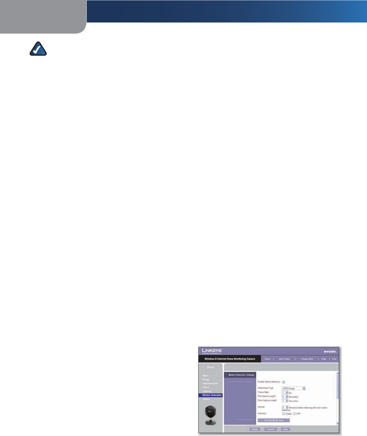
Setup > Motion Detection
The Setup > Motion Detection screen allows you to
configure the Camera’s motion detection settings.
Setup > Motion Detection Screen
Chapter 4Advanced Configuration with the Web-based Utility
26
Wireless-G Internet Home Monitoring Camera
Trigger Motion Detection
Enable Motion Detection Check this box to enable
Motion Detection.
Attachment Type Select the type of attachment to be
sent, either JPEG or Video. If JPEG is selected, a series of
images will be attached to the e-mail as individual files. If
Video is selected, a single video file will be attached.
Frame Rate If the Attachment Type field is set to JPEG,
select the frame rate (number of frames to be captured
per second), from 1 to 5. The default value is 1.
Video Format If the Attachment Type is set to Video,
select the video format, either ASF, MPEG-4, or 3GP.
Pre-Capture Length This refers to video footage up to
the moment when motion is detected. Select how many
seconds’ worth of this video will be saved. This value must
be between 0 and 4 seconds.
Post-Capture Length Select how many seconds’ worth
of video will be saved starting from the moment motion is
detected. This value must be between 1 and 5 seconds.
Interval Enter the time in minutes that must pass
between motion detection events. Valid values are 0-5,
10, or 15. The default is 2. A value of 0 indicates no delay
between events.
Action(s) Select the action(s) to be performed upon
motion detection. Select E-Mail to send an e-mail with a
video attachment to a selected recipient., or select FTP to
send the video to a selected FTP server.
E-Mail Alert
If the Action(s) field is set to E-Mail, fill in the following
fields:
Send To Enter the e-mail address where e-mail will be
sent upon motion detection. You can optionally specify
up to three addresses.
Show “From” as Enter the e-mail address to be used as
the From field in the e-mail to be sent.
Subject Enter the Subject field for the e-mail, consisting
of 48 alphanumeric characters or less.
SMTP Port Number Enter the SMTP port number from 1
to 65535. The default is 25.
SMTP Mail Server If you want to use an SMTP mail server,
check the box next to Specify a SMTP Mail Server. Then
enter the mail server’s name in the field provided.
My Mail Server Requires Authentication If you are using
an SMTP mail server that requires authentication (you
must log in with a username and password), check this
box, then fill in the Account Name and Password fields.
Test E-Mail Click this button to send a test e-mail to the
address indicated by the Send To field.
FTP
If the Action(s) field is set to FTP, fill in the following fields:
FTP Server Enter the FTP server name.
Port Enter the FTP server’s port number.
Login Name and Password Enter the login name and
password for the account on the FTP server.
Passive Mode Select Enable (default) to enable passive
mode, or Disable to disable it.
File Path Name Enter the path to the location where the
file will be saved on the FTP server.
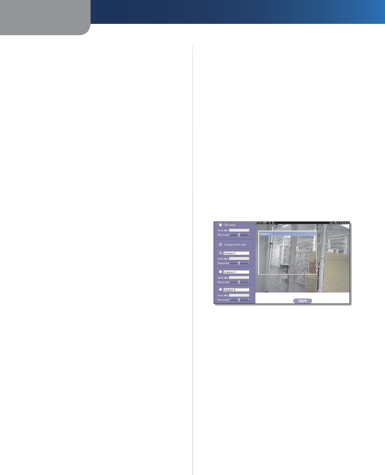
Set Sensitivity Area
Set Sensitivity Area If you want to specify the sensitivity
area settings for motion detection, click this button to
display the Set Sensitivity Area window. The Set Sensitivity
Area window lets you specify the area of the video screen
that is used to detect motion. This is either the full screen,
or up to three user-defined custom areas within the full
screen.
Set Sensitivity Area Window
The following fields appear on the left side of the Set
Sensitivity Area window for each sensitivity area. Specify
the settings as needed, then click Apply.
Full Screen or Window 2-4 This is the name of the
sensitivity area, either Full screen by default, or if
Setting Custom Area is selected, Window 2, Window 3,
or Window 4 (custom areas). To change a custom
area name to a more appropriate name, such as Front
Door, enter the new name in this field.
Setting Custom Area To specify custom area(s) within
the full screen, check this box, then configure up to
three custom sensitivity areas. By default only one
area, Window 2, is selected. To create an additional
area, check the box next to its name. You can move
or resize each area as needed. Custom areas may also
overlap.
Threshold Slide this to the left to reduce the area’s
sensitivity, or to the right to increase sensitivity.
•
•
•
Chapter 4 Advanced Configuration with the Web-based Utility
27
Wireless-G Internet Home Monitoring Camera
New Motion Trigger Schedule
This section allows you to create a schedule that
determines when motion detection will be active. To do
this, you define one or more “trigger” events, or periods
during which motion detection will be in effect. For each
trigger event, fill in the following fields.
Trigger Motion Detection Specify how often this trigger
event occurs: Every day,Weekdays (Mon - Fri), or on
specific days of the week (Sunday to Saturday).
Start Time and End Time Select the starting and ending
times for the event.
Add Click Add to add the new event to the schedule.
Clear Click Clear to clear the schedule of all events.
Delete To delete an event from the Schedule List, select
the event, then click Delete.
Schedule List This displays all of the scheduled trigger
events that you have defined and saved. It is empty by
default.
To save your changes, click Apply. To cancel any unsaved
changes, click Cancel. To get additional information about
the screen’s features, click Help.
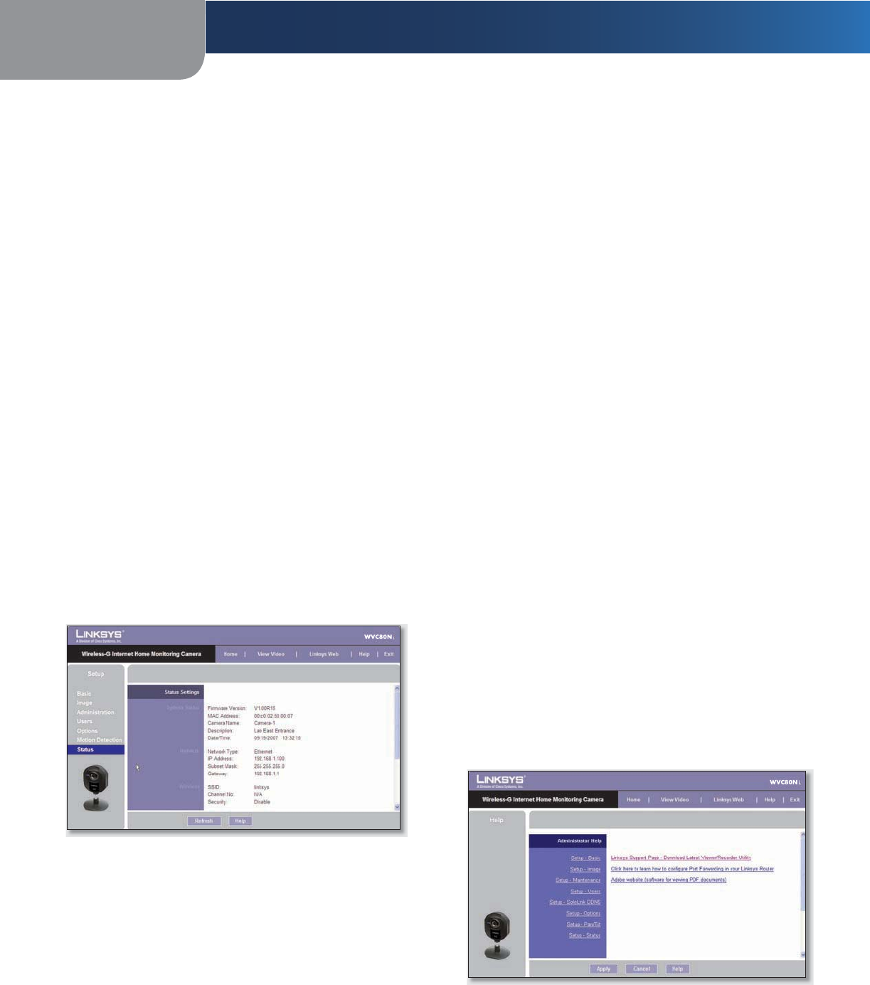
Setup > Status
The Setup > Status screen allows you to view the Camera’s
status information and log.
Setup > Status Screen
System Status
Firmware Version The version of the current firmware
installed.
MAC Address The MAC Address of the Camera is
displayed here.
Camera Name The name you gave to the Camera is
displayed here.
Description Information about the Camera, such as
location, is displayed here.
Date/Time The current date and time are shown here.
Network
Network Type The wireless network’s mode is shown
here.
IP Address The Camera’s IP Address is displayed here.
Subnet Mask The Camera’s Subnet Mask is shown here.
Gateway The Camera’s Gateway address is displayed
here.
Wireless
SSID The wireless network’s SSID or name is shown here.
Channel No The wireless network’s channel setting is
displayed here.
Security The wireless network’s encryption level is shown
here.
Log
System Log This shows the Camera’s activities. To empty
the log, click Clear Log.
To get the Camera’s most up-to-date information, click
Refresh. To get additional information about the screen’s
features, click Help.
Help
Through the Help screen, you’ll find links to additional
resources for the Camera and its Utility. If you select the
Help tab directly from the Welcome screen, then you will
see the User Help screen and will only be able to access
these resources. If you first log in to access the Camera’s
Setup and then select the Help tab, you will see the
Administrator Help screen and will be able to restore
factory defaults and upgrade the Camera’s firmware.
Setup > Help Screen
Setup Click any of the topics in the bar on the left to
get help information.
•

Chapter 4Advanced Configuration with the Web-based Utility
28
Wireless-G Internet Home Monitoring Camera
Linksys Support Page - Download Latest Viewer/
Recorder Utility Click this link to download the most
recent version of the Camera Utility from the Linksys
website, www.linksys.com.
Click here to learn how to configure Port Forwarding
in your Linksys Router If you are going to use the
DDNS Service, you need to set up port forwarding
on your router. For instructions on how to configure
a Linksys router, click this link. If you have a different
router, refer to your router’s documentation.
Adobe website (software for viewing PDF
documents) If you do not have Adobe Acrobat
Reader, click this link to download it.
•
•
•

Appendix A Troubleshooting
29
Wireless-G Internet Home Monitoring Camera
Appendix A:
Troubleshooting
This appendix consists of two parts: “Common Problems
and Solutions” and “Frequently Asked Questions.” This
appendix provides solutions to problems that may occur
during the installation and operation of the Wireless-G
Internet Home Monitoring Camera. Read the description
below to solve your problems. If you can’t find an answer
here, check the Linksys website at www.linksys.com.
Common Problems and Solutions
I can’t view the Camera’s video using Internet Explorer.
Make sure the OCX plug-in was correctly installed.
If you’re not sure, re-install the plug-in by following
these instructions
On the Welcome screen of the Camera’s Web-
based Utility, click View Video.
A screen mentioning a security warning about
an OCX plug-in will appear. Click Yes to allow the
plug-in to be installed.
You should then be able to view the Camera’s
streaming video.
If you still cannot view the video, make sure you
have the rights to install the plug-in in your PC’s
Internet Explorer. If not, log into your computer as an
administrator and install the plug-in.
Then you can check if the OCX plug-in has been
installed. Follow these instructions:
From Internet Explorer, go to Tools and Internet
Options.
On the General screen, click Settings under
Temporary Internet files.
Click View Objects. You should see a file named
NetCamPlayerWeb Control installed.
The OCX plug-in is installed in Internet Explorer, but I
cannot view any video.
Make sure Microsoft Internet Explorer 5.5 or higher is
installed. Then delete the OCX plug-in by following
these instructions:
From Internet Explorer, go to Tools and Internet
Options.
On the General screen, click Settings under
Temporary Internet files.
Click View Objects.
You should see a file named NetCamPlayerWeb
Control installed. Delete this file from the list.
•
•
•
•
•
•
•
•
•
•
The next time you click View Video from the web
browser, you will be prompted to re-install the
OCX plug-in.
When powering on the Camera, I can’t immediately
access the Camera from my computer.
Make sure the Camera’s LED is continuously lit. When it
is flashing, the Camera is initializing.
I’m not able to play my recording video les.
Make sure you have Microsoft Windows Media Player
7 or higher. If you don’t, you can download the latest
version from www.microsoft.com.
I have two Cameras and see two WVC54GCAs listed in
my Camera Utility. When I click to view both Cameras, I
see the video of only one Camera.
Make sure that the Cameras have different camera or
device names. You can change this by using the Web-
based Utility or running the Setup Wizard. If you use
the Web-based Utility, log in and click the Setup tab.
Then on the Basic screen, change the Camera Name.
When I view video remotely via the Internet, the video is
very slow.
Video performance is greatly affected by your Internet
connection speed. You can lower the Camera’s image
quality to speed up the video. Through the Camera’s
Web-based Utility, click the Setup and Image tabs, and
then lower the image quality on the Image screen.
I cannot access the Setup tab of the Camera’s Web-based
Utility.
Make sure you have administrator rights. Only an
administrator can change the Camera’s settings.
I want to access the Camera when I’m away from home,
but somehow I can’t connect.
If your network uses a dynamic IP address supplied
by your ISP, then the IP address you use to reach the
Camera will change as well. You need to use the TZO
DDNS Service, so you can access the Camera using its
domain name while the service keeps track of the IP
address changes. To set up a Dynamic Domain Name
Service (DDNS) account, click the Setup tab of the
Camera’s Web-based Utility, then click the Options
tab. Then configure the settings in the DDNS section
of the screen.
Important: To allow remote access to the Camera, you
will also have to use the port forwarding feature on
your network router.
•

Appendix A Troubleshooting
30
Wireless-G Internet Home Monitoring Camera
Frequently Asked Questions
Can I view video using a Macintosh or Netscape
Navigator?
The Camera is designed for computers running a
Windows operating system and Internet Explorer 5.5
or higher. You cannot view video on a Macintosh. If
you only have Netscape, you can view video using the
Camera Utility. See “Chapter 3: Installing and Using the
Camera Utility.”
Can I directly connect the Camera to wired and wireless
networks at the same time?
No. Before powering on the Camera, you should
decide if you want to connect the Camera to a wireless
network via an access point or to a wired network. If
your wireless and wired networks are bridged, then
you can access the Camera from any networked
computer, but the Camera must be directly connected
to only one of the networks.
To connect the Camera to a wireless network, power
on the Camera with no network cable attached.
The Camera will be ready for use when the LED is lit
continuously.
To connect the Camera to a wired network, connect
the network cable to the Camera, and then power it
on. The Camera will be ready for use when the LED is
lit continuously.
Can I install the Camera outdoors?
No, the Camera was not designed for outdoors usage.
I’ve recorded video for a few hours. Why do I see multiple
les saved on my computer?
The recording function saves video in chunks; each
chunk is a maximum of one hour in duration. For
example, if you have recorded five continuous hours,
then you will see five files saved on your computer.
This keeps files from getting too large.
Do I need to install the Linksys Multi-Camera Viewer and
Recorder Utility?
Installation is optional. You can view video using
Microsoft Internet Explorer 5.5 or higher. If you don’t
want to use the recording function, then you don’t
need to install the Multi-Camera Viewer and Recorder
Utility.
Can I specify who gets to view the Camera’s video?
Yes. Access the Camera’s Web-based Utility, and click
the Setup tab. After you log in, click the Users tab.
You will be able to restrict access to users you have
entered in the database. See “Chapter 4: Advanced
Configuration with the Web-based Utility.”
Can I add a time stamp to the video?
Yes. Access the Camera’s Web-based Utility, and
click the Setup tab. After you log in, click the Image
tab. You will be able to add a time stamp as well as
descriptive text to the video. See “Chapter 4: Advanced
Configuration with the Web-based Utility.”
How many users can view the Camera’s video at the
same time?
Users at four different PCs can simultaneously view the
Camera’s video.
What is the IEEE 802.11b standard?
It is one of the IEEE standards for wireless networks. T he
802.11b standard allows wireless networking hardware
from different manufacturers to communicate,
provided that the hardware complies with the 802.11b
standard. T he 802.11b standard states a maximum data
transfer rate of 11Mbps and an operating frequency of
2.4GHz.
What is the IEEE 802.11g standard?
It is one of the IEEE standards for wireless networks. T he
802.11g standard allows wireless networking hardware
from different manufacturers to communicate,
provided that the hardware complies with the 802.11g
standard. T he 802.11g standard states a maximum data
transfer rate of 54Mbps and an operating frequency of
2.4GHz.
What IEEE 802.11b features are supported?
The product supports the following IEEE 802.11b
functions:
CSMA/CA plus Acknowledge protocol
Multi-Channel Roaming
Automatic Rate Selection
RTS/CTS feature •Fragmentation
Power Management
What IEEE 802.11g features are supported?
The product supports the following IEEE 802.11g
functions:
CSMA/CA plus Acknowledge protocol
OFDM protocol
Multi-Channel Roaming
Automatic Rate Selection
RTS/CTS feature
•
•
•
•
•
•
•
•
•
•

Appendix A Troubleshooting
31
Wireless-G Internet Home Monitoring Camera
Fragmentation
Power Management
What is ad-hoc mode?
When a wireless network is set to ad-hoc mode, the
wireless-equipped computers are configured to
communicate directly with each other. The ad-hoc
wireless network will not communicate with any wired
network.
What is infrastructure mode?`
When a wireless network is set to infrastructure mode,
the wireless network is configured to communicate
with a wired network through a wireless access point
or router.
WEB: If your questions are not addressed here,
refer to the Linksys website, www.linksys.com
•
•

Appendix B Wireless Security Checklist
32
Wireless-G Internet Home Monitoring Camera
Appendix B:
Wireless Security Checklist
Wireless networks are convenient and easy to install, so
homes with high-speed Internet access are adopting them
at a rapid pace. Because wireless networking operates by
sending information over radio waves, it can be more
vulnerable to intruders than a traditional wired network.
Like signals from your cellular or cordless phones, signals
from your wireless network can also be intercepted. Since
you cannot physically prevent someone from connecting
to your wireless network, you need to take some additional
steps to keep your network secure.
1. Change the default wireless
network name or SSID
Wireless devices have a default wireless network name
or Service Set Identifier (SSID) set by the factory. This
is the name of your wireless network, and can be up
to 32 characters in length. Linksys wireless products
use linksys as the default wireless network name. You
should change the wireless network name to something
unique to distinguish your wireless network from other
wireless networks that may exist around you, but do not
use personal information (such as your Social Security
number) because this information may be available for
anyone to see when browsing for wireless networks.
2. Change the default password
For wireless products such as access points, routers, and
gateways, you will be asked for a password when you
want to change their settings. T hese devices have a default
password set by the factory. The Linksys default password
is admin. Hackers know these defaults and may try to
use them to access your wireless device and change your
network settings. To thwart any unauthorized changes,
customize the device’s password so it will be hard to
guess.
3. Enable MAC address filtering
Linksys routers and gateways give you the ability to
enable Media Access Control (MAC) address filtering. The
MAC address is a unique series of numbers and letters
assigned to every networking device. With MAC address
filtering enabled, wireless network access is provided
solely for wireless devices with specific MAC addresses.
For example, you can specify the MAC address of each
computer in your home so that only those computers can
access your wireless network.
4. Enable encryption
Encryption protects data transmitted over a wireless
network. Wi-Fi Protected Access (WPA/WPA2) and Wired
Equivalency Privacy (WEP) offer different levels of security
for wireless communication.
A network encrypted with WPA/WPA2 is more secure
than a network encrypted with WEP, because WPA/WPA2
uses dynamic key encryption. To protect the information
as it passes over the airwaves, you should enable the
highest level of encryption supported by your network
equipment.
WEP is an older encryption standard and may be the
only option available on some older devices that do not
support WPA.
General Network Security Guidelines
Wireless network security is useless if the underlying
network is not secure.
Password protect all computers on the network and
individually password protect sensitive files.
Change passwords on a regular basis.
Install anti-virus software and personal firewall
software.
Disable file sharing (peer-to-peer). Some applications
may open file sharing without your consent and/or
knowledge.
Additional Security Tips
Keep wireless routers, access points, or gateways away
from exterior walls and windows.
Turn wireless routers, access points, or gateways
off when they are not being used (at night, during
vacations).
Use strong passphrases that are at l east eight characters
in length. Combine letters and numbers to avoid using
standard words that can be found in the dictionary.
WEB: For more information on wireless
security, visit www.linksys.com/security
•
•
•
•
•
•
•

Appendix CSpecifications
33
Wireless-G Internet Home Monitoring Camera
Appendix C:
Specifications
Model WVC54GCA
Standards IEEE 802.11g, IEEE 802.3,
IEEE 802.3u
Ports Ethernet, Power
Buttons Reset
LEDs Power
Cabling Type Cat5
Number of Antennas 1 Internal
Connector Type N/A
Detachable Antenna No
UPnP able/cert UPnP Advertise
.Net Support N/A
Security Features WEP-64, WEP-128, WPA,
WPA2
Image Sensor CMOS
Lens Fixed Focus
Resolution 640 x 480, 320 x 240,
160 x 128
Relative Illumination 5.1 Lux
Eective Focus 3 mm
Sensitivity 3.0V/Lux-sec
Field of View 61.48 degrees
Compression Algorithm MPEG-4 and MJPEG
Record File Format ASF
Brightness Auto/Manual Adjustment
Environmental
Dimensions 3.54" x 4.72" x 1.46"
(90 x 120 x 37mm)
Weight 4.59 oz (0.13 kg)
Power 5V 1A
Certication FCC, CE, CB, UL, C-Tick,
PSB/SPRING, IDA
Operating Temp. 32 to 104ºF (0 to 40ºC)
Storage Temp. -4 to 158ºF (–20 to 70ºC)
Operating Humidity 10 to 80% Noncondensing
Storage Humidity 0 to 90% Noncondensing
Minimum System Requirements
1 Camera PC with 2 GHz or faster
processor
512 MB RAM
Microsoft Windows 2000,
XP or Vista
500MB of available hard
drive space
Graphics card with a
minimum of 128 MB
Internet Explorer 6.0 (or
above), Mozilla Firefox,
Netscape 7.0 (or above)
DirectX 9.0 (or above)
CD-ROM Drive
Windows Media Player 9 or
higher
Up to 9 Cameras PC with 3 GHz dual-core
processor
1 GB RAM
Microsoft Windows 2000,
XP or Vista
4 GB of available hard
drive space
Graphics card with a
minimum of 256 MB
Internet Explorer 6.0 (or
above), Mozilla Firefox,
Netscape 7.0 (or above)
DirectX 9.0 (or above)
CD-ROM Drive
Windows Media Player 9 or
higher

Appendix D Warranty Information
34
Wireless-G Internet Home Monitoring Camera
Limited Warranty
Linksys warrants to You that, for a period of one year
(the "Warranty Period"), your Linksys Product will be
substantially free of defects in materials and workmanship
under normal use. Your exclusive remedy and Linksys’
entire liability under this warranty will be for Linksys at
its option to repair or replace the Product or refund Your
purchase price less any rebates. This limited warranty
extends only to the original purchaser.
If the Product proves defective during the Warranty
Period call Linksys Technical Support in order to obtain
a Return Authorization Number, if applicable. BE SURE
TO HAVE YOUR PROOF OF PURCHASE ON HAND WHEN
CALLING. If You are requested to return the Product, mark
the Return Authorization Number clearly on the outside
of the package and include a copy of your original proof
of purchase. RETURN REQUESTS CANNOT BE PROCESSED
WITHOUT PROOF OF PURCHASE. You are responsible
for shipping defective Products to Linksys. Linksys pays
for UPS Ground shipping from Linksys back to You only.
Customers located outside of the United States of America
and Canada are responsible for all shipping and handling
charges.
ALL IMPLIED WARRANTIES AND CONDITIONS OF
MERCHANTABILITY OR FITNESS FOR A PARTICULAR
PURPOSE ARE LIMITED TO THE DURATION OF
THE WARRANTY PERIOD. ALL OTHER EXPRESS OR
IMPLIED CONDITIONS, REPRESENTATIONS AND
WARRANTIES, INCLUDING ANY IMPLIED WARRANTY OF
NON-INFRINGEMENT, ARE DISCLAIMED. Some j urisdictions
do not allow limitations on how long an implied warranty
lasts, so the above limitation may not apply to You. This
warranty gives You specific legal rights, and You may also
have other rights which vary by jurisdiction.
This warranty does not apply if the Product (a) has been
altered, except by Linksys, (b) has not been installed,
operated, repaired, or maintained in accordance with
instructions supplied by Linksys, or (c) has been subjected
to abnormal physical or electrical stress, misuse,
negligence, or accident. In addition, due to the continual
development of new techniques for intruding upon and
attacking networks, Linksys does not warrant that the
Product will be free of vulnerability to intrusion or attack.
TO THE EXTENT NOT PROHIBITED BY LAW, IN NO EVENT
WILL LINKSYS BE LIABLE FOR ANY LOST DATA, REVENUE
OR PROFIT, OR FOR SPECIAL, INDIRECT, CONSEQUENTIAL,
INCIDENTAL OR PUNITIVE DAMAGES, REGARDLESS OF THE
THEORY OF LIABILITY (INCLUDING NEGLIGENCE), ARISING
OUT OF OR RELATED TO THE USE OF OR INABILITY TO
USE THE PRODUCT (INCLUDING ANY SOFTWARE), EVEN
IF LINKSYS HAS BEEN ADVISED OF THE POSSIBILITY OF
SUCH DAMAGES. IN NO EVENT WILL LINKSYS’ LIABILITY
EXCEED THE AMOUNT PAID BY YOU FOR THE PRODUCT.
The foregoing limitations will apply even if any warranty or
remedy provided under this Agreement fails of its essential
purpose. Some jurisdictions do not allow the exclusion or
limitation of incidental or consequential damages, so the
above limitation or exclusion may not apply to You.
Please direct all inquiries to: Linksys, P. O. Box 18558, Irvine,
CA 92623.
Appendix D:
Warranty Information

Appendix E Regulatory Information
35
Wireless-G Internet Home Monitoring Camera
Appendix E:
Regulatory Information
FCC Statement
This device complies with Part 15 of the FCC Rules.
Operation is subject to the following two conditions: (1)
This device may not cause harmful interference, and (2) this
device must accept any interference received, including
interference that may cause undesired operation.
This product has been tested and complies with the
specifications for a Class B digital device, pursuant to Part
15 of the FCC Rules. These limits are designed to provide
reasonable protection against harmful interference in
a residential installation. This equipment generates,
uses, and can radiate radio frequency energy and, if not
installed and used according to the instructions, may
cause harmful interference to radio communications.
However, there is no guarantee that interference will not
occur in a particular installation. If this equipment does
cause harmful interference to radio or television reception,
which is found by turning the equipment off and on, the
user is encouraged to try to correct the interference by
one or more of the following measures:
Reorient or relocate the receiving antenna
Increase the separation between the equipment or
devices
Connect the equipment to an outlet other than the
receiver’s
Consult a dealer or an experienced radio/TV technician
for assistance
FCC Caution: Any changes or modifications not expressly
approved by the party responsible for compliance could
void the user’s authority to operate this equipment.
FCC Radiation Exposure Statement
This equipment complies with FCC radiation exposure
limits set forth for an uncontrolled environment. This
equipment should be installed and operated with
minimum distance 20cm between the radiator and your
body.
This transmitter must not be co-located or operating in
conjunction with any other antenna or transmitter. IEEE
802.11b or 802.11g operation of this product in the USA is
firmware-limited to channels 1 through 11.
•
•
•
•
Safety Notices
Caution: To reduce the risk of fire, use only No.26 AWG
or larger telecommunication line cord.
Do not use this product near water, for example, in a
wet basement or near a swimming pool.
Avoid using this product during an electrical storm.
There may be a remote risk of electric shock from
lightning.
WARNING: This product contains lead, known
to the State of California to cause cancer, and
birth defects or other reproductive harm. Wash
hands after handling.
Industry Canada Statement
This Class B digital apparatus complies with Canadian
ICES-003 and RSS210.
Operation is subject to the following two conditions:
This device may not cause interference and
This device must accept any interference, including
interference that may cause undesired operation of the
device. This device has been designed to operate with
an antenna having a maximum gain of
having a higher gain is strictly prohibited per regulations
of Industry Canada. The required antenna impedance
is 50 ohms.
To reduce potential radio interference to other users,
the antenna type and its gain should be so chosen
that the EIRP is not more than required for successful
communication.
Industry Canada Radiation Exposure Statement:
This equipment complies with IC radiation exposure limits
set forth for an uncontrolled environment. T his equipment
should be installed and operated with minimum distance
20cm between the radiator & your body.
This transmitter must not be co-located or operating in
conjunction with any other antenna or transmitter.
•
•
•
1.
2.
1.5dBi. Antenna

Appendix E Regulatory Information
36
Wireless-G Internet Home Monitoring Camera
Avis d’Industrie Canada
Cet appareil numérique de la classe B est conforme aux
normes NMB-003 et RSS210 du Canada.
L’utilisation de ce dispositif est autorisée seulement aux
conditions suivantes :
il ne doit pas produire de brouillage et
il doit accepter tout brouillage radioélectrique reçu,
même si ce brouillage est susceptible de compromettre
le fonctionnement du dispositif. Le dispositif a été
conçu pour fonctionner avec une antenne ayant un gain
maximum de 2 dBi. Les règlements d’Industrie Canada
interdisent strictement l’utilisation d’antennes dont le
gain est supérieur à cette limite. L’impédance requise
de l’antenne est de 50 ohms.
Afin de réduire le risque d’interférence aux autres
utilisateurs, le type d’antenne et son gain doivent
être choisis de façon à ce que la puissance isotrope
rayonnée équivalente (p.i.r.e.) ne soit pas supérieure
au niveau requis pour obtenir une communication
satisfaisante.
Avis d’Industrie Canada concernant l’exposition
aux radiofréquences :
Ce matériel est conforme aux limites établies par IC
en matière d’exposition aux radiofréquences dans un
environnement non contrôlé. Ce matériel doit être installé
et utilisé à une distance d’au moins 20 cm entre l’antenne
et le corps de l’utilisateur.
L’émetteur ne doit pas être placé près d’une autre antenne
ou d’un autre émetteur, ou fonctionner avec une autre
antenne ou un autre émetteur.
Wireless Disclaimer
The maximum performance for wireless is derived from
IEEE Standard 802.11 specifications. Actual performance
can vary, including lower wireless network capacity,
data throughput rate, range and coverage. Performance
depends on many factors, conditions and variables,
including distance from the access point, volume of
network traffic, building materials and construction,
operating system used, mix of wireless products used,
interference and other adverse conditions.
1.
2.
Avis de non-responsabilité concernant les
appareils sans fil
Les performances maximales pour les réseaux sans fil
sont tirées des spécifications de la norme IEEE 802.11.
Les performances réelles peuvent varier, notamment
en fonction de la capacité du réseau sans fil, du débit
de la transmission de données, de la portée et de la
couverture. Les performances dépendent de facteurs,
conditions et variables multiples, en particulier de la
distance par rapport au point d’accès, du volume du trafic
réseau, des matériaux utilisés dans le bâtiment et du
type de construction, du système d’exploitation et de la
combinaison de produits sans fil utilisés, des interférences
et de toute autre condition défavorable.
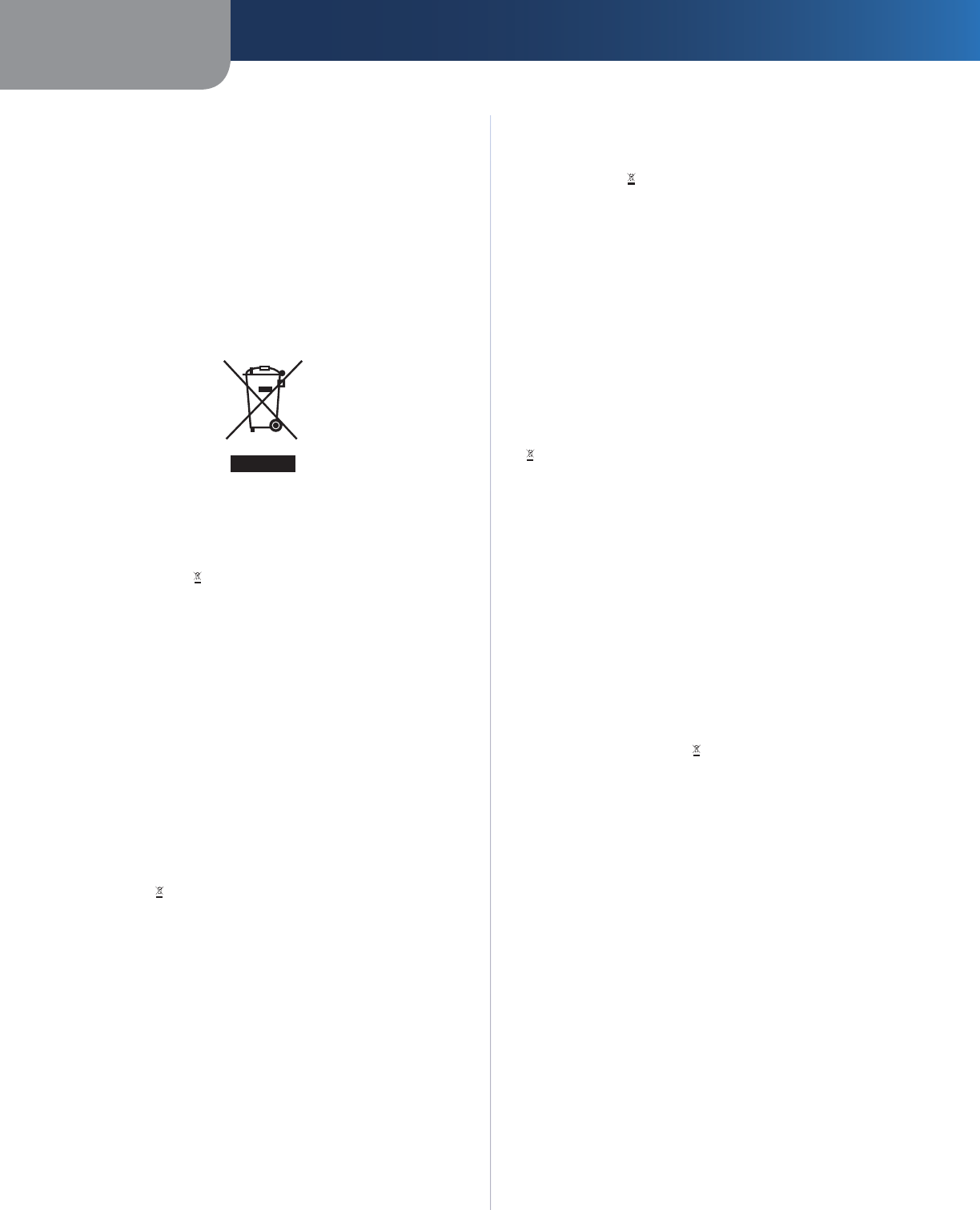
Appendix E Regulatory Information
37
Wireless-G Internet Home Monitoring Camera
User Information for Consumer Products
Covered by EU Directive 2002/96/EC on
Waste Electric and Electronic Equipment
(WEEE)
This document contains important information for users
with regards to the proper disposal and recycling of
Linksys products. Consumers are required to comply with
this notice for all electronic products bearing the following
symbol:
English - Environmental Information for Customers in
the European Union
European Directive 2002/96/EC requires that the equipment
bearing this symbol on the product and/or its packaging must
not be disposed of with unsorted municipal waste. The symbol
indicates that this product should be disposed of separately
from regular household waste streams. It is your responsibility to
dispose of this and other electric and electronic equipment via
designated collection facilities appointed by the government or
local authorities. Correct disposal and recycling will help prevent
potential negative consequences to the environment and
human health. For more detailed information about the disposal
of your old equipment, please contact your local authorities,
waste disposal service, or the shop where you purchased the
product.
Български (Bulgarian) - Информация относно
опазването на околната среда за потребители в
Европейския съюз
Европейска директива 2002/96/EC изисква уредите, носещи
този символ върху изделието и/или опаковката му, да не
се изхвърля т с несортирани битови отпадъци. Символът
обозначава, че изделието трябва да се изхвърля отделно от
сметосъбирането на обикновените битови отпадъци. Ваша
е отговорността този и другите електрически и електронни
уреди да се изхвърлят в предварително определени от
държавните или общински органи специализирани пунктове
за събиране. Правилното изхвърляне и рециклиране
ще спомогнат да се предотвратят евентуални вредни за
околната среда и здравето на населението последствия. За
по-подробна информация относно изхвърлянето на вашите
стари уреди се обърнете към местните власти, службите за
сметосъбиране или магазина, от който сте закупили уреда.
Ceština (Czech) - Informace o ochraně životního
prostředí pro zákazníky v zemích Evropské unie
Evropská směrnice 2002/96/ES zakazuje, aby zařízení označené
tímto symbolem na produktu anebo na obalu bylo likvidováno
s netříděným komunálním odpadem. Tento symbol udává,
že daný produkt musí být likvidován odděleně od běžného
komunálního odpadu. Odpovídáte za likvidaci tohoto produktu
a dalších elektrických a elektronických zařízení prostřednictvím
určených sběrných míst stanovených vládou nebo místními
úřady. Správná likvidace a recyklace pomáhá předcházet
potenciálním negativním dopadům na životní prostředí a lidské
zdraví. Podrobnější informace o likvidaci starého vybavení si
laskavě vyžádejte od místních úřadů, podniku zabývajícího se
likvidací komunálních odpadů nebo obchodu, kde jste produkt
zakoupili.
Dansk (Danish) - Miljøinformation for kunder i EU
EU-direktiv 2002/96/EF kræver, at udstyr der bærer dette symbol
på produktet og/eller emballagen ikke må bortskaffes som
usorteret kommunalt affald. Symbolet betyder, at dette produkt
skal bortskaffes adskilt fra det almindelige husholdningsaffald.
Det er dit ansvar at bortskaffe dette og andet elektrisk og
elektronisk udstyr via bestemte indsamlingssteder udpeget
af staten eller de lokale myndigheder. Korrekt bortskaffelse
og genvinding vil hjælpe med til at undgå mulige skader for
miljøet og menneskers sundhed. Kontakt venligst de lokale
myndigheder, renovationstjenesten eller den butik, hvor du
har købt produktet, angående mere detaljeret information om
bortskaffelse af dit gamle udstyr.
Deutsch (German) - Umweltinformation für Kunden
innerhalb der Europäischen Union
Die Europäische Richtlinie 2002/96/EC verlangt, dass technische
Ausrüstung, die direkt am Gerät und/oder an der Verpackung mit
diesem Symbol versehen ist , nicht zusammen mit unsortiertem
Gemeindeabfall entsorgt werden darf. Das Symbol weist darauf
hin, dass das Produkt von regulärem Haushaltmüll getrennt
entsorgt werden sollte. Es liegt in Ihrer Verantwortung, dieses
Gerät und andere elektrische und elektronische Geräte über
die dafür zuständigen und von der Regierung oder örtlichen
Behörden dazu bestimmten Sammelstellen zu entsorgen.
Ordnungsgemäßes Entsorgen und Recyceln trägt dazu bei,
potentielle negative Folgen für Umwelt und die menschliche
Gesundheit zu vermeiden. Wenn Sie weitere Informationen zur
Entsorgung Ihrer Altgeräte benötigen, wenden Sie sich bitte an
die örtlichen Behörden oder städtischen Entsorgungsdienste
oder an den Händler, bei dem Sie das Produkt erworben haben.

Appendix E Regulatory Information
38
Wireless-G Internet Home Monitoring Camera
Eesti (Estonian) - Keskkonnaalane informatsioon
Euroopa Liidus asuvatele klientidele
Euroopa Liidu direktiivi 2002/96/EÜ nõuete kohaselt on
seadmeid, millel on tootel või pakendil käesolev sümbol ,
keelatud kõrvaldada koos sorteerimata olmejäätmetega. See
sümbol näitab, et toode tuleks kõrvaldada eraldi tavalistest
olmejäätmevoogudest. Olete kohustatud kõrvaldama käesoleva
ja ka muud elektri- ja elektroonikaseadmed riigi või kohalike
ametiasutuste poolt ette nähtud kogumispunktide kaudu.
Seadmete korrektne kõrvaldamine ja ringlussevõtt aitab vältida
võimalikke negatiivseid tagajärgi keskkonnale ning inimeste
tervisele. Vanade seadmete kõrvaldamise kohta täpsema
informatsiooni saamiseks võtke palun ühendust kohalike
ametiasutustega, jäätmekäitlusfirmaga või kauplusega, kust te
toote ostsite.
Español (Spanish) - Información medioambiental para
clientes de la Unión Europea
La Directiva 2002/96/CE de la UE exige que los equipos que
lleven este símbolo en el propio aparato y/o en su embalaje
no deben eliminarse junto con otros residuos urbanos no
seleccionados. El símbolo indica que el producto en cuestión
debe separarse de los residuos domésticos convencionales con
vistas a su eliminación. Es responsabilidad suya desechar este y
cualesquiera otros aparatos eléctricos y electrónicos a través de
los puntos de recogida que ponen a su disposición el gobierno y
las autoridades l ocales. Al desechar y reciclar correctamente estos
aparatos estará contribuyendo a evitar posibles consecuencias
negativas para el medio ambiente y la salud de las personas. Si
desea obtener información más detallada sobre la eliminación
segura de su aparato usado, consulte a las autoridades locales,
al servicio de recogida y eliminación de residuos de su zona o
pregunte en la tienda donde adquirió el producto.
ξλληνικά (Greek) - Στοιχεία περιβαλλοντικής
προστασίας για πελάτες εντός της Ευρωπαϊκής
Ένωσης
Η Κοινοτική Οδηγία 2002/96/EC απαιτεί ότι ο εξοπλισμός ο οποίος
φέρει αυτό το σύμβολο στο προϊόν και/ή στη συσκευασία
του δεν πρέπει να απορρίπτεται μαζί με τα μικτά κοινοτικά
απορρίμματα. Το σύμβολο υποδεικνύει ότι αυτό το προϊόν θα
πρέπει να απορρίπτεται ξεχωριστά από τα συνήθη οικιακά
απορρίμματα. Είστε υπεύθυνος για την απόρριψη του παρόντος
και άλλου ηλεκτρικού και ηλεκτρονικού εξοπλισμού μέσω των
καθορισμένων εγκαταστάσεων συγκέντρωσης απορριμμάτων οι
οποίες παρέχονται από το κράτος ή τις αρμόδιες τοπικές αρχές.
Η σωστή απόρριψη και ανακύκλωση συμβάλλει στην πρόληψη
πιθανών αρνητικών συνεπειών για το περιβάλλον και την υγεία.
Για περισσότερες πληροφορίες σχετικά με την απόρριψη του
παλιού σας εξοπλισμού, παρακαλώ επικοινωνήστε με τις τοπικές
αρχές, τις υπηρεσίες απόρριψης ή το κατάστημα από το οποίο
αγοράσατε το προϊόν.
Français (French) - Informations environnementales
pour les clients de l’Union européenne
La directive européenne 2002/96/CE exige que l’équipement
sur lequel est apposé ce symbole sur le produit et/ou son
emballage ne soit pas jeté avec les autres ordures ménagères. Ce
symbole indique que le produit doit être éliminé dans un circuit
distinct de celui pour les déchets des ménages. Il est de votre
responsabilité de jeter ce matériel ainsi que tout autre matériel
électrique ou électronique par les moyens de collecte indiqués
par le gouvernement et les pouvoirs publics des collectivités
territoriales. L’élimination et le recyclage en bonne et due forme
ont pour but de lutter contre l’impact néfaste potentiel de ce
type de produits sur l’environnement et la santé publique. Pour
plus d’informations sur le mode d’élimination de votre ancien
équipement, veuillez prendre contact avec les pouvoirs publics
locaux, le service de traitement des déchets, ou l’endroit où vous
avez acheté le produit.
Italiano (Italian) - Informazioni relative all’ambiente
per i clienti residenti nell’Unione Europea
La direttiva europea 2002/96/EC richiede che le apparecchiature
contrassegnate con questo simbolo sul prodotto e/o
sull’imballaggio non siano smaltite insieme ai rifiuti urbani
non differenziati. Il simbolo indica che questo prodotto non
deve essere smaltito insieme ai normali rifiuti domestici. È
responsabilità del proprietario smaltire sia questi prodotti sia
le altre apparecchiature elettriche ed elettroniche mediante
le specifiche strutture di raccolta indicate dal governo o dagli
enti pubblici locali. Il corretto smaltimento ed il riciclaggio
aiuteranno a prevenire conseguenze potenzialmente negative
per l’ambiente e per la salute dell’essere umano. Per ricevere
informazioni più dettagliate circa lo smaltimento delle vecchie
apparecchiature in Vostro possesso, Vi invitiamo a contattare gli
enti pubblici di competenza, il servizio di smaltimento rifiuti o il
negozio nel quale avete acquistato il prodotto.
Latviešu valoda (Latvian) - Ekoloģiska informācija
klientiem Eiropas Savienības jurisdikcijā
Direktīvā 2002/96/EK ir prasība, ka aprīkojumu, kam pievienota
zīme uz paša izstrādājuma vai uz tā iesaiņojuma, nedrīkst
izmest nešķirotā veidā kopā ar komunālajiem atkritumiem
(tiem, ko rada vietēji iedzīvotāji un uzņēmumi). Šī zīme nozīmē
to, ka šī ierīce ir jāizmet atkritumos tā, lai tā nenonāktu kopā ar
parastiem mājsaimniecības atkritumiem. Jūsu pienākums ir šo
un citas elektriskas un elektroniskas ierīces izmest atkritumos,
izmantojot īpašus atkritumu savākšanas veidus un līdzekļus, ko
nodrošina valsts un pašvaldību iestādes. Ja izmešana atkritumos
un pārstrāde tiek veikta pareizi, tad mazinās iespējamais
kaitējums dabai un cilvēku veselībai. Sīkākas ziņas par
novecojuša aprīkojuma izmešanu atkritumos jūs varat saņemt
vietējā pašvaldībā, atkritumu savākšanas dienestā, kā arī veikalā,
kur iegādājāties šo izstrādājumu.

Appendix E Regulatory Information
39
Wireless-G Internet Home Monitoring Camera
Lietuvškai (Lithuanian) - Aplinkosaugos informacija,
skirta Europos Sąjungos vartotojams
Europos direktyva 2002/96/EC numato, kad įrangos, kuri ir
kurios pakuotė yra pažymėta šiuo simboliu (įveskite simbolį),
negalima šalinti kartu su nerūšiuotomis komunalinėmis
atliekomis. Šis simbolis rodo, kad gaminį reikia šalinti atskirai
nuo bendro buitinių atliekų srauto. Jūs privalote užtikrinti, kad
ši ir kita elektros ar elektroninė įranga būtų šalinama per tam
tikras nacionalinės ar vietinės valdžios nustatytas atliekų rinkimo
sistemas. Tinkamai šalinant ir perdirbant atliekas, bus išvengta
galimos žalos aplinkai ir žmonių sveikatai. Daugiau informacijos
apie jūsų senos įrangos šalinimą gali pateikti vietinės valdžios
institucijos, atliekų šalinimo tarnybos arba parduotuvės, kuriose
įsigijote tą gaminį.
Malti (Maltese) - Informazzjoni Ambjentali għal Klijenti
fl-Unjoni Ewropea
Id-Direttiva Ewropea 2002/96/KE titlob li t-tagħmir li jkun fih is-
simbolu fuq il-prodott u/jew fuq l-ippakkjar ma jistax jintrema
ma’ skart muniċipali li ma ġiex isseparat. Is-simbolu jindika
li dan il-prodott għandu jintrema separatament minn ma’ l-
iskart domestiku regolari. Hija responsabbiltà tiegħek li tarmi
dan it-tagħmir u kull tagħmir ieħor ta’ l-elettriku u elettroniku
permezz ta’ faċilitajiet ta’ ġbir appuntati apposta mill-gvern jew
mill-awtoritajiet lokali. Ir-rimi b’mod korrett u r-riċiklaġġ jgħin
jipprevjeni konsegwenzi negattivi potenzjali għall-ambjent u
għas-saħħa tal-bniedem. Għal aktar informazzjoni dettaljata
dwar ir-rimi tat-tagħmir antik tiegħek, jekk jogħġbok ikkuntattja
lill-awtoritajiet lokali tiegħek, is-servizzi għar-rimi ta’ l-iskart, jew
il-ħanut minn fejn xtrajt il-prodott.
Magyar (Hungarian) - Környezetvédelmi információ az
európai uniós vásárlók számára
A 2002/96/EC számú európai uniós irányelv megkívánja, hogy
azokat a termékeket, amelyeken, és/vagy amelyek csomagolásán
az alábbi címke megjelenik, tilos a többi szelektálatlan lakossági
hulladékkal együtt kidobni. A címke azt jelöli, hogy az adott
termék kidobásakor a szokványos háztartási hulladékelszállítási
rendszerektõl elkülönített eljárást kell alkalmazni. Az Ön
felelõssége, hogy ezt, és más elektromos és elektronikus
berendezéseit a kormányzati vagy a helyi hatóságok által
kijelölt gyűjtõredszereken keresztül számolja fel. A megfelelõ
hulladékfeldolgozás segít a környezetre és az emberi egészségre
potenciálisan ártalmas negatív hatások megelõzésében. Ha
elavult berendezéseinek felszámolásához további részletes
információra van szüksége, kérjük, lépjen kapcsolatba a helyi
hatóságokkal, a hulladékfeldolgozási szolgálattal, vagy azzal
üzlettel, ahol a terméket vásárolta.
Nederlands (Dutch) - Milieu-informatie voor klanten
in de Europese Unie
De Europese Richtlijn 2002/96/EC schrijft voor dat apparatuur die
is voorzien van dit symbool op het product of de verpakking,
niet mag worden ingezameld met niet-gescheiden huishoudelijk
afval. Dit symbool geeft aan dat het product apart moet worden
ingezameld. U bent zelf verantwoordelijk voor de vernietiging
van deze en andere elektrische en elektronische apparatuur via de
daarvoor door de landelijke of plaatselijke overheid aangewezen
inzamelingskanalen. De juiste vernietiging en recycling van
deze apparatuur voorkomt mogelijke negatieve gevolgen voor
het milieu en de gezondheid. Voor meer informatie over het
vernietigen van uw oude apparatuur neemt u contact op met
de plaatselijke autoriteiten of afvalverwerkingsdienst, of met de
winkel waar u het product hebt aangeschaft.
Norsk (Norwegian) - Miljøinformasjon for kunder i EU
EU-direktiv 2002/96/EF krever at utstyr med følgende symbol
avbildet på produktet og/eller pakningen, ikke må kastes
sammen med usortert avfall. Symbolet indikerer at dette
produktet skal håndteres atskilt fra ordinær avfallsinnsamling
for husholdningsavfall. Det er ditt ansvar å kvitte deg med
dette produktet og annet elektrisk og elektronisk avfall via egne
innsamlingsordninger slik myndighetene eller kommunene
bestemmer. Korrekt avfallshåndtering og gjenvinning vil
være med på å forhindre mulige negative konsekvenser for
miljø og helse. For nærmere informasjon om håndtering av
det kasserte utstyret ditt, kan du ta kontakt med kommunen,
en innsamlingsstasjon for avfall eller butikken der du kjøpte
produktet.
Polski (Polish) - Informacja dla klientów w Unii
Europejskiej o przepisach dotyczących ochrony
środowiska
Dyrektywa Europejska 2002/96/EC wymaga, aby sprzęt
oznaczony symbolem znajdującym się na produkcie i/lub jego
opakowaniu nie był wyrzucany razem z innymi niesortowanymi
odpadami komunalnymi. Symbol ten wskazuje, że produkt
nie powinien być usuwany razem ze zwykłymi odpadami z
gospodarstw domowych. Na Państwu spoczywa obowiązek
wyrzucania tego i innych urządzeń elektrycznych oraz
elektronicznych w punktach odbioru wyznaczonych przez władze
krajowe lub lokalne. Pozbywanie się sprzętu we właściwy sposób
i jego recykling pomogą zapobiec potencjalnie negatywnym
konsekwencjom dla środowiska i zdrowia ludzkiego. W celu
uzyskania szczegółowych informacji o usuwaniu starego sprzętu,
prosimy zwrócić się do lokalnych władz, służb oczyszczania
miasta lub sklepu, w którym produkt został nabyty.

Appendix E Regulatory Information
40
Wireless-G Internet Home Monitoring Camera
Português (Portuguese) - Informação ambiental para
clientes da União Europeia
A Directiva Europeia 2002/96/CE exige que o equipamento
que exibe este símbolo no produto e/ou na sua embalagem
não seja eliminado junto com os resíduos municipais não
separados. O símbolo indica que este produto deve ser
eliminado separadamente dos resíduos domésticos regulares.
É da sua responsabilidade eliminar este e qualquer outro
equipamento eléctrico e electrónico através das instalações
de recolha designadas pelas autoridades governamentais ou
locais. A eliminação e reciclagem correctas ajudarão a prevenir
as consequências negativas para o ambiente e para a saúde
humana. Para obter informações mais detalhadas sobre a
forma de eliminar o seu equipamento antigo, contacte as
autoridades locais, os serviços de eliminação de resíduos ou o
estabelecimento comercial onde adquiriu o produto.
Română (Romanian) - Informaţii de mediu pentru
clienţii din Uniunea Europeană
Directiva europeană 2002/96/CE impune ca echipamentele care
prezintă acest simbol pe produs şi/sau pe ambalajul acestuia să
nu fie casate împreună cu gunoiul menajer municipal. Simbolul
indică faptul că acest produs trebuie să fie casat separat de
gunoiul menajer obişnuit. Este responsabilitatea dvs. să casaţi
acest produs şi alte echipamente electrice şi electronice prin
intermediul unităţilor de colectare special desemnate de guvern
sau de autorităţile locale. Casarea şi reciclarea corecte vor ajuta
la prevenirea potenţialelor consecinţe negative asupra sănătăţii
mediului şi a oamenilor. Pentru mai multe informaţii detaliate
cu privire la casarea acestui echipament vechi, contactaţi
autorităţile locale, serviciul de salubrizare sau magazinul de la
care aţi achiziţionat produsul.
Slovenčina (Slovak) - Informácie o ochrane životného
prostredia pre zákazníkov v Európskej únii
Podľa európskej smernice 2002/96/ES zariadenie s týmto
symbolom na produkte a/alebo jeho balení nesmie byť
likvidované spolu s netriedeným komunálnym odpadom.
Symbol znamená, že produkt by sa mal likvidovať oddelene
od bežného odpadu z domácností. Je vašou povinnosťou
likvidovať toto i ostatné elektrické a elektronické zariadenia
prostredníctvom špecializovaných zberných zariadení určených
vládou alebo miestnymi orgánmi. Správna likvidácia a recyklácia
pomôže zabrániť prípadným negatívnym dopadom na životné
prostredie a zdravie ľudí. Ak máte záujem o podrobnejšie
informácie o likvidácii starého zariadenia, obráťte sa, prosím, na
miestne orgány, organizácie zaoberajúce sa likvidáciou odpadov
alebo obchod, v ktorom ste si produkt zakúpili.
Slovenčina (Slovene) - Okoljske informacije za stranke
v Evropski uniji
Evropska direktiva 2002/96/EC prepoveduje odlaganje opreme,
označene s tem simbolom – na izdelku in/ali na embalaži – med
običajne, nerazvrščene odpadke. Ta simbol opozarja, da je treba
izdelek odvreči ločeno od preostalih gospodinjskih odpadkov.
Vaša odgovornost je, da to in preostalo električno in elektronsko
opremo odnesete na posebna zbirališča, ki jih določijo
državne ustanove ali lokalna uprava. S pravilnim odlaganjem
in recikliranjem boste preprečili morebitne škodljive vplive na
okolje in zdravje ljudi. Če želite izvedeti več o odlaganju stare
opreme, se obrnite na lokalno upravo, odpad ali trgovino, kjer
ste izdelek kupili.
Suomi (Finnish) - Ympäristöä koskevia tietoja EU-
alueen asiakkaille
EU-direktiivi 2002/96/EY edellyttää, että jos laitteistossa on tämä
symboli itse tuotteessa ja/tai sen pakkauksessa, laitteistoa
ei saa hävittää lajittelemattoman yhdyskuntajätteen mukana.
Symboli merkitsee sitä, että tämä tuote on hävitettävä erillään
tavallisesta kotitalousjätteestä. Sinun vastuullasi on hävittää
tämä elektroniikkatuote ja muut vastaavat elektroniikkatuotteet
viemällä tuote tai tuotteet viranomaisten määräämään
keräyspisteeseen. Laitteiston oikea hävittäminen estää
mahdolliset kielteiset vaikutukset ympäristöön ja ihmisten
terveyteen. Lisätietoja vanhan laitteiston oikeasta hävitystavasta
saa paikallisilta viranomaisilta, jätteenhävityspalvelusta tai siitä
myymälästä, josta ostit tuotteen.
Svenska (Swedish) - Miljöinformation för kunder i
Europeiska unionen
Det europeiska direktivet 2002/96/EC kräver att utrustning med
denna symbol på produkten och/eller förpackningen inte får
kastas med osorterat kommunalt avfall. Symbolen visar att denna
produkt bör kastas efter att den avskiljts från vanligt hushållsavfall.
Det faller på ditt ansvar att kasta denna och annan elektrisk och
elektronisk utrustning på fastställda insamlingsplatser utsedda
av regeringen eller lokala myndigheter. Korrekt kassering och
återvinning skyddar mot eventuella negativa konsekvenser
för miljön och personhälsa. För mer detaljerad information om
kassering av din gamla utrustning kontaktar du dina lokala
myndigheter, avfallshanteringen eller butiken där du köpte
produkten.
WEB: For additional information, please visit
www.linksys.com
7101210NC-AI