LITE ON TECHNOLOGY 143V622PT Wireless camera User Manual
LITE-ON Technology Corp. Wireless camera
User Manual
180° CAMERA
WITH DIGITAL
PAN / TILT / ZOOM
QUICK INSTALLATION GUIDE
ADC-V622 SMARTER
VIDEO
SOLUTIONS
Quick Installation Guide | 3
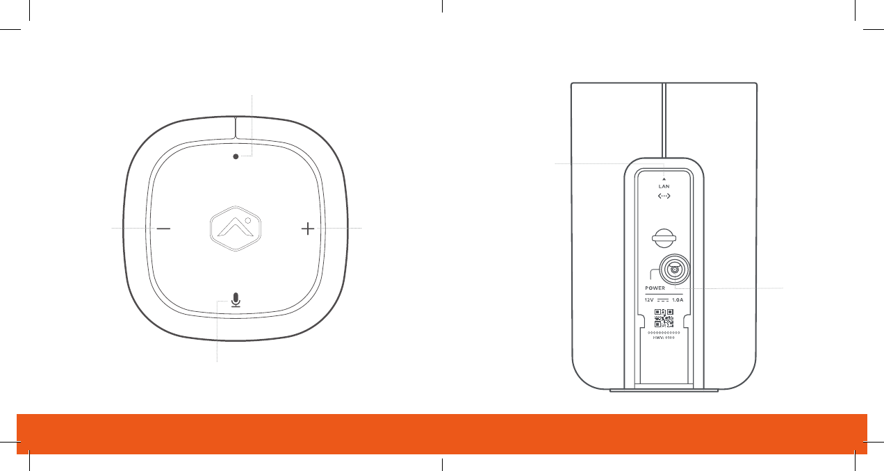
Menu
Call-Out
Button
Volume Down
(Menu Scroll)
Volume Up
(Menu Scroll)
Ethernet
(PoE Capable)
Power

1 | ADC-V622 180° Camera with Digital Pan / Tilt / Zoom Quick Installation Guide | 2
180° CAMERA WITH
DIGITAL PAN / TILT / ZOOM
PRE-INSTALLATION CHECKLIST
• ADC-V622 camera (included)
• AC power adapter (included, required for non-PoE connections)
• Broadband (Cable, DSL, or Fiber Optic) Internet connection
• A computer, tablet or smartphone with Wi-Fi is required if the
router does not have the Wi-Fi Protected Setup (WPS) feature
• An Ethernet / Cat5 cable (for PoE or wired setup)
• Login and Password for the Alarm.com account to which
you will add the camera
There are three options for connecting the ADC-V622 to the network: Ethernet
Mode, Wi-Fi Protected Setup (WPS) Mode, and Access Point (AP) Mode.
Add the Camera to
an Alarm.com Account
Complete these steps prior to installing the camera
ETHERNET MODE
1 Using an Ethernet cable, connect the camera to the network.
2 Connect the camera’s AC power adapter and plug it into
a non-switched outlet (if not using a PoE connection).
3 Add the device by either selecting the account in MobileTech
or
www.alarm.com/addcamera
4 Select the camera from the video device list or type in its
MAC address to begin adding the camera. The camera’s
MAC address is located on the back of the camera near
the power cable.
5
Customer Website.

3 | ADC-V622 180° Camera with Digital Pan / Tilt / Zoom Quick Installation Guide | 4
You can now power down the camera and install it in its
final location using the included hardware.
AP MODE
1 Connect the camera’s AC power adapter and plug it into
a non-switched outlet.
2 Press the Menu button and use the Volume buttons to scroll
to the Access Point Mode (follow the audio prompts or look
3 Press the Menu button to activate Access Point Mode.
4 On an Internet enabled device, connect to the Wi-Fi network
of the ADC-V622’s MAC address, which is located on the back
of the device near the power cord.
5 On the same device, open a web browser and enter
instructions to add the ADC-V622 to the Wi-Fi network.
The LED will be solid green when the connection is complete.
6 Add the device to the account by either selecting the account
in MobileTech OR by using a web browser and entering the
7 Select the camera from the video device list or type in its
MAC address to begin adding the camera. The camera’s
MAC address is located on the back of the camera near
the power cable.
8
Customer Website.
You can now power down the camera and install it in its
final location using the included hardware.
WPS MODE
1 Connect the camera’s AC power adapter and plug it into
a non-switched outlet.
2 Press the Menu button and use the Volume buttons to scroll
to the WPS menu option (follow the audio prompts or look
3 Press the Menu button to activate WPS Mode.

5 | ADC-V622 180° Camera with Digital Pan / Tilt / Zoom Quick Installation Guide | 6
4 Activate the WPS Mode on the router. The ADC-V622 will
begin to connect to the Wi-Fi network. The LED will be solid
green when the connection is complete.
5 Add the device to the account by either selecting the account
in MobileTech OR by using a web browser and entering the
6 Select the camera from the video device list or type in its
MAC address to begin adding the camera. The camera’s
MAC address is located on the back of the camera near
the power cable.
7
Customer Website.
You can now power down the camera and install it in its
final location using the included hardware.
Green | Solid
Red | Solid
Internet connection
No network connection
Local network connection
System booting
Green | Flashing
Red | Flashing
STATUS
Local network and internet connection
No local network or internet connection
Local network connection only, no internet
Camera is booting
LED Reference Guide

7 | ADC-V622 180° Camera with Digital Pan / Tilt / Zoom Quick Installation Guide | 8
WIRELESS ENROLLMENT
AP Mode
White | Flashing
To enter AP mode, push the Menu button
and use the Volume buttons to scroll to
AP Mode. See instructions above to add
the camera to your router and account
using AP mode.
WPS Mode
Blue | Flashing
To enter WPS mode, push the Menu button
and use the Volume buttons to scroll to
WPS Mode. See instructions above to add
the camera to your router and account
using WPS mode.
Bluetooth pairing
Yellow | Flashing
To pair with Bluetooth, push the Menu
button and use the Volume buttons to
scroll to Bluetooth Mode.
Factory Reset
Red & Green | Flashing
FACTORY RESET
Warning: This will restore factory-default settings to the
camera. If already installed, the camera may need to be removed
from the Alarm.com account and re-added after a factory reset.
To perform a factory reset, push the Menu button and use the
Volume buttons to scroll to the Factory Reset option. Follow the
audio prompts to initiate Factory Reset.

9 | ADC-V622 180° Camera with Digital Pan / Tilt / Zoom Quick Installation Guide | 10
Troubleshooting
1 If you have issues connecting the camera to the account,
power cycle the camera. If using the AC adapter, unplug
the power jack from the camera and then plug it back in
to restore power. If using PoE, unplug the Ethernet jack
from the camera and then plug it back in to restore power.
2 If issues persist, try resetting the camera to factory defaults.
Press the Menu button and use the Volume buttons to scroll
to the Factory Reset option. Follow the audio prompts to
initiate Factory Reset. The camera will reboot with factory
defaults. If the camera was previously installed on an
Alarm.com account, it will need to be deleted before it
can be installed again.
QUESTIONS?
FEDERAL COMMUNICATION COMMISSION
INTERFERENCE STATEMENT
This equipment has been tested and found to comply with the limits for a Class B digital device, pursuant
to Part 15 of the FCC Rules. These limits are designed to provide reasonable protection against
harmful interference in a residential installation. This equipment generates, uses and can radiate radio
frequency energy and, if not installed and used in accordance with the instructions, may cause harmful
interference to radio communications. However, there is no guarantee that interference will not occur
in a particular installation. If this equipment does cause harmful interference to radio or television
• Reorient or relocate the receiving antenna.
• Increase the separation between the equipment and receiver.
•
connected.
•
for compliance could void the user’s authority to operate this equipment.
(1) This device may not cause harmful interference, and (2) this device must accept any interference
received, including interference that may cause undesired operation.
This device and its antenna(s) must not be co-located or operating in conjunction with any other antenna
or transmitter.
For product available in the USA/Canada market, only channel 1~11 can be operated. Selection of other
channels is not possible.
This device is restricted to indoor use.

11 | ADC-V622 180° Camera with Digital Pan / Tilt / Zoom Quick Installation Guide | 12
FCC RADIATION EXPOSURE STATEMENT
This equipment should be installed and operated with minimum distance 20cm between the radiator &
your body.
IC S TATEM ENT
(1) This device may not cause interference; and
(2) This device must accept any interference, including interference that may cause undesired operation
of the device.
de brouillage, et (2) l’utilisateur de l’appareil doit accepter tout brouillage radioélectrique subi, même si
le brouillage est susceptible d’en compromettre le fonctionnement.
IC RSS-247 LE-LAN DEVICES
This device is restricted to indoor use.
The device for operation in the band 5150-5250 MHz is only for indoor use to reduce the potential for
harmful interference to co-channel mobile satellite systems;
les dispositifs fonctionnant dans la bande 5150-5250 MHz sont réservés uniquement pour une utilisation
Users should also be advised that high-power radars are allocated as primary users (i.e. priority users) of
the bands 5250-5350 MHz and 5650-5850 MHz and that these radars could cause interference and/or
damage to LE-LAN devices.
5250MHz to 5350MHz and 5650MHz to 5850MHz bands. These radars could cause interference and/or
damage to Wireless LAN devices used in Canada.
la priorité) pour les bandes 5250 - 5350 MHz et 5650 - 5850 MHz. Ces radars pourraient causer du
IC RADIATION EXPOSURE STATEMENT
environment. This equipment should be installed and operated with minimum distance 20cm
between the radiator & your body.
environnement non contrôlé. Cet équipement doit être installé et utilisé avec un minimum de 20cm
de distance entre la source de rayonnement et votre corps
The transmitter module may not be co-located with any other transmitter or antenna.
Le module émetteur peut ne pas être coïmplanté avec un autre émetteur ou antenne.
CAN ICES-3 (B)/NMB-3(B)
For product available in the USA/Canada market, only channel 1~11 can be operated.
Selection of other channels is not possible.
2.4 GHz
5 GHz
© 2018 Alarm.com. All rights reserved.
8281 Greensboro Drive, Suite 100
Tysons, VA 22102 180202