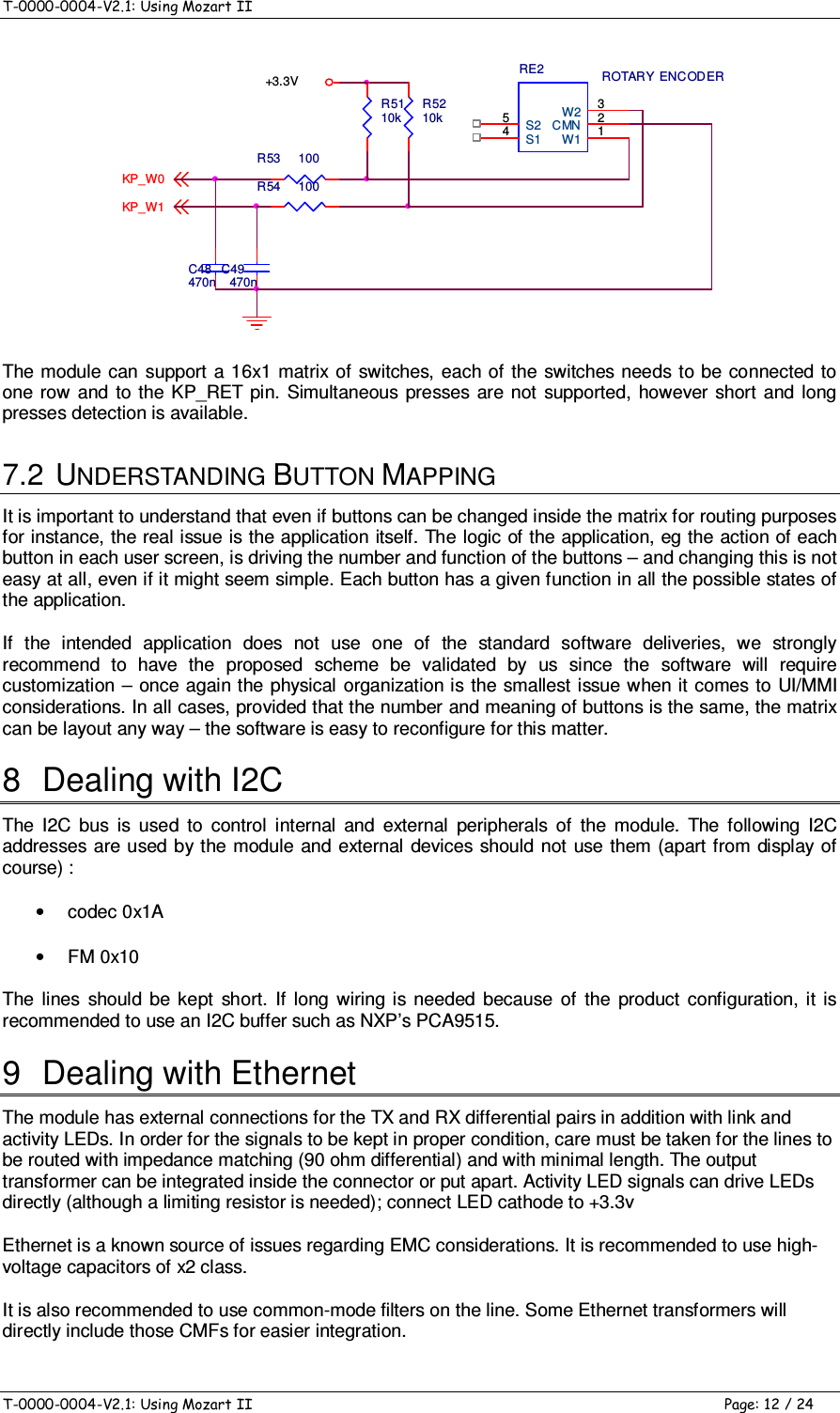
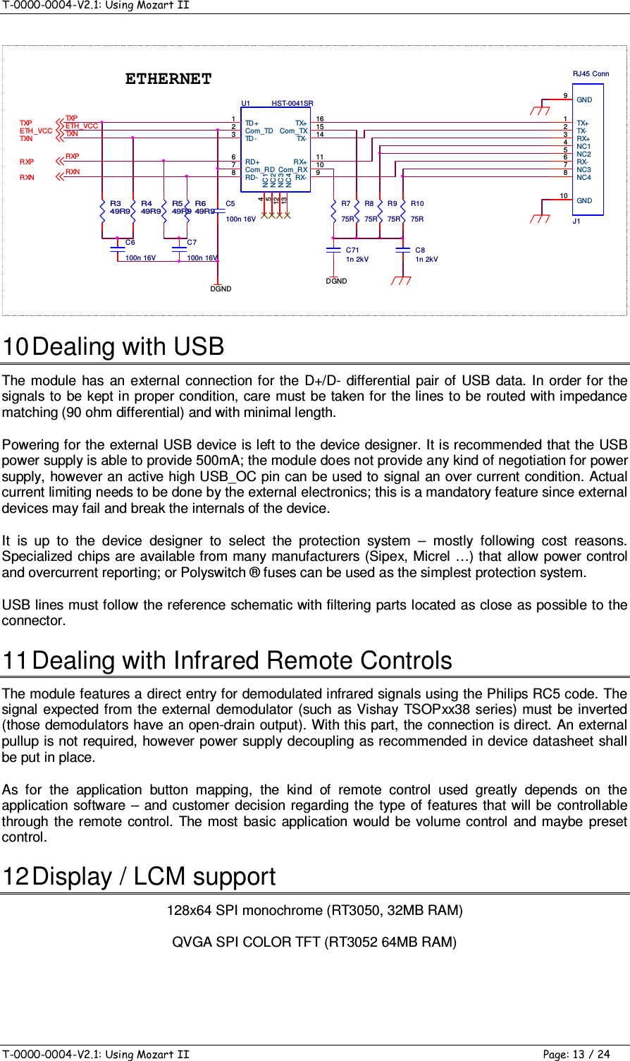
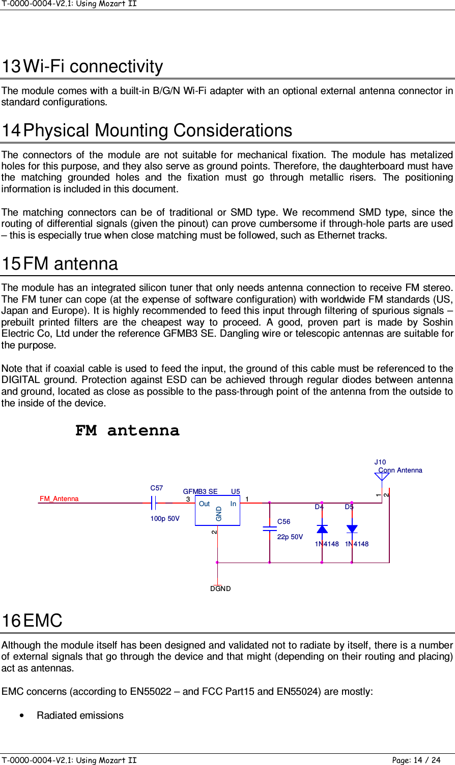
LITE ON TECHNOLOGY AWOXMII2 Mozart II User Manual

LITE-ON Technology Corp. Mozart II

user manual

AWOX, S.A. 93 Place Pierre Duhem 34000 MONTPELLIER, France Tel: +33 4 67 47 10 00, Fax: +33 4 67 47 10 15 www.awox.com  contact@awox.com  T-0000-0005-V2.1: Digital Mozart II  Module  Page: 1 / 4      Technical Note  Digital Mozart II  Module 1  Introduction The original design of Mozart II includes everything an audio system designer needs in terms of digital to  analog conversion  and  analog  signal  management  ready  to feed to analog amplifiers  or  outputs. Basically, ADC,DAC, FM tuner and all volume control and equalization are built-in. Some  applications  do not  make use of  analog output  (for instance,  connecting  the  module  to some digital audio processor does not require analog) or will make use of their own converters for feature or cost  reasons.  Therefore,  Mozart  II  can  be  delivered  as  “digital  only”,  which  means  only  the  digital stream is provided to the outside world. The general  considerations on Mozart II use can be found in  the master documentation for the full-fledged module. This document only describes the changes between the two versions. It is therefore recommended to read the full-fledged version documentation before this one. A reference schematic for Mozart II Digital implementation is provided. 2  Clocking As in any digital audio system, clocking is an important point. Mozart II is using I2S 3-Wire protocol by default and needs a Master Clock frequency to be provided on I2S_REF pin and equal to 11.2896MHz or  12.288MHz.  The  internal  module  dividers  provide  the  according  I2S_LRCK,  I2S_BCLK  and  the I2S_DATA is latched conforming to I2S 16 bits per channel standard. Awox may carry on particular studies upon customer request for specific unsupported sound peripherals. 3  DACs and amplifiers 3.1  SUPPORTED DACS The reference DAC for use with Mozart II Digital is Wolfson Micro WM8711. This low-cost DAC allows simple and easy construction of analog products using Mozart II Digital. It is the one that is used on the  Analog  variant  of  the  module  and  is  therefore  not  part  of  the  reference  schematic  for  sake  of explanation; Mozart II Digital makes little sense versus the analog variant if the same peripherals are used; the goal is to be able to use feature-rich peripherals for mid to high-end devices. Please contact AwoX for more information. 3.2  AMPLIFIERS The reference digital amplifier, Class-D, for use with Mozart II Digital is the Cirrus Logic CS4525. It has provision for analog parts without adding external circuitry while still giving the benefit of the low-cost and simplicity of Mozart II Digital.
T-0000-0005-V2.1: Digital Mozart II  Module    T-0000-0005-V2.1: Digital Mozart II  Module  Page: 2 / 4 4  Other Peripherals 4.1  S/PDIF The  optical  and  coaxial  outputs  for  S/PDIF  are  driven  by  a  Cirrus  Logic  CS8406  S/PDIF  encoder. Software re-sampling is used for non-native frequencies. The Quartet II reference schematic includes this  part  configured  to  drive an optical transmitter. To  support coaxial  SPDIF output,  please  contact AwoX for more information. 4.2  FM TUNER The  reference  tuner for  use  with  Mozart  II  Digital is  the Silicon Labs  Si4704.  The tuner  has analog outputs,  which means  that  its  use  on  a  daughterboard  requires  proper  analog  signal  handling.  The part is the same that is used on the analog variant of Mozart. 5  Daughterboard Schematic Description Front Panel, iPod , and Rear Panel Interface are identical to the digital version (with the exception of the Line Out  replaced by Line In for demonstration purposes, but this input is directly managed by the amplifier used). Therefore, the description only highlights the Main Board which is quite simple. 5.1  AUDIO AMP SECTION (PAGE 1) The amplifier U4 and the module use external I2S clocking, providing the main frequency from crystal Y2. 5.2  FM TUNER & INTERCONNECT (PAGE 2) The FM tuner requires the use of a band-pass filter for proper FM reception. It uses its own external clock (Y3). Note that the interrupt line to the processor is shared and therefore open-drain, J20 is the connection to interface board. 5.3  5.3 POWER & CONNECTORS (PAGE 3) Strictly identical to analog version.
AWOX, S.A. 93 Place Pierre Duhem 34000 MONTPELLIER, France Tel: +33 4 67 47 10 00, Fax: +33 4 67 47 10 15 www.awox.com  contact@awox.com  T-0000-0004-V2.1: Using Mozart II  Page: 1 / 24      Technical Note  Using Mozart II 1  Introduction to Mozart II Module  HARDWARE FEATURES  • RaLink RT3050/RT3052 system-on-chip • Memory - 32 MB 133 MHZ SDRAM (64 MB optional) - 32 MB NAND flash memory for system  • FM Tuner • Audio - Stereo output (L/R RCA, daughterboard*) w/ headphones and line level - Stereo input (L/R RCA, daughterboard*) - I2S output, 16bits stereo - SPDIF output (Optical/RCA,  daughterboard*) • Storage - USB 2.0 host (daughterboard*) • Network - 10/100Mb Ethernet MAC & PHY - Onboard Wireless LAN 802.11b/g/n - Encryption support: 40- and 128- bit WEP, WPA, CCX, TKIP & AES - WPS 2.0 security • Interface - Control LCD screen via  SPI; supports monochrome and color TFT - Support for keyboard, up to 16 keys and one rotary encoder - Infrared decoder function for RC5 & NEC - Adjustable analog output within 0 ~ 3,3V range - External FM antenna (mini jack, daughterboard*) • Clock - Alarm, wake-up, snooze and sleep features • Power Supply required - 3.3V for main activity • Dimensions - 80 x 60 x 17 mm  SOFTWARE FEATURES • Stored in NAND flash memory, fully upgradable via the Internet  • Audio decoders  - MP3 - WMA - WAV - AAC-LC - Real • AwoX streaming engine - HTTP - MMS • Internet Radio Directory - vTuner Internet  - baracoda • Digital Media Player  (compliant with DLNA 1.5 guidelines) • Digital Media Renderer (compliant with DLNA 1.5 guidelines) • Linux Kernel 2.6.21 • Linux Drivers  - Monochrome 128x64 LCD and QVGA TFT - Keyboard/keypad input - Wi-Fi Interface - FM tuner with optional RDS - Full-speed USB 2.0 host - Ethernet - SPDIF transmitter - Wi-Fi STA and AP  2  Introduction to Mozart II Module AwoX  S.A.  has  developed  and  is  manufacturing  an  electronic  module,  codenamed  “Mozart  II”, that allows  building many types of connected audio platforms at  the  cost of simple expansion  boards for power  supply,  network  connection,  audio  outputs  and  man-machine  interface.  All  the  standard peripherals of such a device can be connected to the module which will be able to drive them with few or no additional glue. The module requires +3.3v, 1.2 A power supply.
T-0000-0004-V2.1: Using Mozart II    T-0000-0004-V2.1: Using Mozart II  Page: 2 / 24 The  module  is  delivered  with  operating  system  and  applications.  There  is  a  standard  peripheral  / function support set that can be customized upon request. The module has built-in features but is also able  to  support  external  peripherals.  Customer  support for  additional  peripherals  can  be  integrated after feasibility study. Additionally, the module comes with a set of preprogrammed pins for standard uses, but most of them have  multiplexing  capabilities  allowing  for  different  usage  patterns.  Please  contact  your  local  sales representative for customization information or feasibility questions. Overall, the Mozart II module allows for  easy design of equipment with standard  features  as well as room for customization and evolution.  Custom design services (for both hardware  and software) are available. 3  Module Block Diagram  4  Standard Features and Peripherals 4.1  MODULE INTERNALS On the module itself, the “smart” peripherals available are a stereo PLL FM tuner, an audio codec with line in, line out and amplified headphones output, and a built-in Ethernet PHY for 100baseT networks. The  module  has  an  internal  Wi-Fi  interface.  The  FM  tuner  audio  output  is  available  on  the  main connector as well as the Codec  Line In.  The  module features  32MB of fully reprogrammable NAND flash  and  RAM.  FM  Tuner  and  Audio  Codec  are  internally  linked  to  the  I2C  bus,  which  might  be shared with external peripherals.
T-0000-0004-V2.1: Using Mozart II    T-0000-0004-V2.1: Using Mozart II  Page: 3 / 24 All  the  internal  peripherals  are  supported  by  the  software  distribution,  as  well  as  some  external peripherals. The module has its own reset circuitry, which generates an externally available signal for resetting external devices. This reset line will be asserted at power on, when a power supply failure is detected,  or  when  the  software  reboots  the  module  (this  can  happen  after  firmware  upgrade  for instance). If the reset line is not used by an external device, care must be taken to reset the device at least under power on and power failure conditions by additional means. 4.2  EXTERNAL CONTROLS & INPUTS The  module  features  a  number  of  pins  that  allow  sensing  data  from  the  outside  world  as  well  as control  information.  Several  digital  I/O  pins  are  available.  All  digital  inputs  are  interrupt-capable  in order to trigger predetermined software behaviors upon given external conditions. Digital outputs are 3.3v CMOS outputs; their maximum output current is 10 mA. 4.3  EXTERNAL BUSES 4.3.1 I2C The module acts as an I2C compatible master controller. The default bus speed is 100KHz. The bus level is 3.3v; the module already has 4k7 pull-up resistors on both SCL and SDA lines. The external lines, if used without repeater, should be kept as short as possible. 4.3.2 USB Signals for an USB host interface are available. The interface is fully compliant with USB 2.0 fullspeed standard.  The powering  of external USB devices is  left  to  the integrator and must comply with USB constraints (coil decoupling of powering and appropriate impedance matching and adaptation of lines). Most often, the host interface will be used for USB keys or mass storage devices. Should more USB ports be needed, an external hub can be added on the module port. DGNDJ2Conn USB ty pe A horizUSB_5V1HOST_D-2HOST_D+3DGND4FGND 6FGND5L1 120R 100MHzUSBL2120R 100MHzC347p 50VC447p 50VHD MHD PDGNDDGNDDGND+C247u 16VDGN DDGND DGNDDGNDVCC5VC1100n 16VHDMR2DNPESD5 ESD6ESD7 ESD8USB_GNDR14k7HDPUSB_5VDGNDDGNDU2 LM3525M-LIN7FLG2EN1GND3NC1 4NC2 5OUT1 6OUT2 8DGN D USB Mass Storage Support is part of the standard software delivery. Note that USB device or OTG can be supported but is not part of the standard implementation
T-0000-0004-V2.1: Using Mozart II    T-0000-0004-V2.1: Using Mozart II  Page: 4 / 24 4.4  AUDIO SECTION 4.4.1 LINE OUT The module has a  Line Out  stereo connection. The lines are DC  coupled with a  1.35V offset and a 0.7Vpp modulation range. Depending on the software configuration, the modulation level can be fixed or may follow user volume settings. 4.4.2 FM OUT The analog outputs of the FM tuner are available to provide flexibility for out-of-module analog paths. The normal way to use them is to link to Line_In pins; if an external multiplexer has to be used, then the SELECT signal can be used to distinguish between FM and external source. 4.4.3 LINE IN The  module  has  a  Line  In  stereo  connection.  The  lines  are  DC  coupled  and  will  accept  a  0.7Vpp modulation range. Depending on the software configuration, the input level can be fixed or may follow user settings. Input impedance is 47kOhms. 4.4.4 HP OUT The module has a Headphones amplified stereo connection. The lines are DC coupled with a 1.35V offset and will drive 16 Ohm headphones at up to 30 mW and 32 Ohm headphones at up to 15 mW.  4.5  VOLUME CONTROL STRATEGIES The module features  two audio outputs; one is a  line-level output and one is a headphones output. Both  can  be  controlled  by  software  independently,  however  the  way  to  use  them  depends  on  the global design of the target product and the envisioned use cases. The headphones  output is capable of  driving  standard  32 Ohm headphones at up to 15  mW output power. It is up to the customer to decide  whether this is enough or not; if not  external amplification must be used. If headphones plug need to be added, there are two solutions: •  Use the module headphones output. In this case, if internal speaker cut-off is required, it must be implemented in relationship with the amplifier. •  Use the amplifier output to drive the headphones. When simultaneous speakers and line out is required, in most cases the volume of the line outputs will not vary. In this case, the only solution is to use the headphones output to feed the internal amplifier (with jack before or after amplifier), and to connect the line outputs directly to the line out connector. The  module  has  a  STANDBY  and  a  MUTE  signal.  The  MUTE  signal  will  be  active  as  soon  as  the module  is  not  producing  audio  signals.  The  STANDBY  signal  needs  to  control  powering  of  the amplifier,  while  the  MUTE  signal  can  be  used  to  make  sure  audio  outputs from the  module  will  be turned  down.  It  is  important  to  note  that  at  initialization  time,  the  audio  output  of  the  module  can produce spurious sounds – this is why the external logic must take care of not amplifying them. In case of required mono internal speaker, the internal amplifier will be monophonic as well and will be fed with a mix of the left and right signals. In this case, it will not be possible to have a design on which the heapdhones jack will be connected to the internal amplifier – the only way to have stereo output is to use the amplified outputs of the module.
T-0000-0004-V2.1: Using Mozart II    T-0000-0004-V2.1: Using Mozart II  Page: 5 / 24 It is important to note that the integrity of the audio outputs cannot  be guaranteed while the module initializes. The module has a MUTE signal that must be used to physically remove the signal at places where it  would be audible (namely,  the audio  amplifier).  The MUTE  signal  is  raised  as soon  as  the module is  not  outputting  any  sound on its  audio outputs  in standard  software deliveries.  It is highly recommended to design the external circuitry with an amplifier that supports built-in muting instead of using additional circuitry. The following drawings illustrate how to use outputs from the module in various cases. The simplest possible equipment has only internal speaker; if the device is monophonic then left and right channels must be mixed before use – the output from the module will always be stereo; using only one channel will not be sufficient.   Adding  headphones  output  is  only  at  cost  of  the  connector  (the  internal  amplifier  can  be  mono  or stereo  of course). However, this configuration does not allow automatic cutoff when headphones are plugged in:   If cutoff is required, it must be either managed outside of the module, or the following scheme can be used. In this case, impedance match at amplifier input is different from the LineOut feed:
T-0000-0004-V2.1: Using Mozart II    T-0000-0004-V2.1: Using Mozart II  Page: 6 / 24  For complete equipment, Line Outputs can be used as well. In this kind of structure, the Line Outputs will often be fixed-volume:  Finally,  “accessory”  devices  will  not  have  internal  speakers  (but  they  can  still  use  headphones  !). Internal  amplification  is  removed  in  this  case  and  the  amplifier  feed  is  connected  directly  to  output jacks. 4.6  USING LINE INPUT The Line In terminals can be used to grab audio from an external source, such as an MP3 player, CD player, cassette deck, iPod, etc. The audio analog is routed through the internal DAC therefore sound control for it is available. The Line Input and the FM tuner mode are exclusive. If no Line In is requested, then the FM Out should be tied directly to Line In. 4.7  POWERING CONSIDERATIONS The  module  requires  3.3v  power  rail.  The  3.3v  is  the  main  power  supply  and,  as  all  digital  power supplies, is highly subject to digital commutation bursts and high current flows. It is therefore important that  this  line  presents  low  impedance,  is  well  decoupled,  and  not  too  long  from  the  power  supply location. There is no recommended scheme for powering – it really depends on the kind of peripherals used in the  rest  of  the  device.  If  the  main  PSU  is  +5V  (this  will  be  the  case  if  the  device  does  not  have amplification, such as  a  Hi-Fi accessory) then  it makes  sense to use linear regulation, while DC/DC scheme could be preferred if the main PSU is +12V. In case of DC/DC use, EMC concerns arise.
T-0000-0004-V2.1: Using Mozart II    T-0000-0004-V2.1: Using Mozart II  Page: 7 / 24 Some  low-cost  circuits  will  generate  spurious  oscillations  at  high  frequency,  therefore  creating unwanted emissions that can go quite high in terms of frequency. It is recommended that the DC/DC converters  are  well-studied  and  tested  before  integration,  especially  when  it  comes  to  noise  and stability  considerations.  Because  of  the  inherent  burst  structure  of  the  Wi-Fi  current  consumption, good transient response is a key factor of the power supply design – as well as track impedance and proper grounding & decoupling of the module. 4.8  POWER MANAGEMENT FEATURES To some extent, the module can manage power supply for itself and the external peripherals and be informed  of  the  type  of  powering  it  can  count  on.  However,  even  if  running  a  Mozart  II-based application on batteries can be done, it is not really the primary target of the module – continuous Wi-Fi communication and decoding is not really energy-saving. A possible scenario would be to build a “transportable device” (that is, mobility is a secondary function not supposed to be used every time) so a minimal power management has been put in place. The module will raise the  Standby line when a low  power / idle condition is active while  reducing its own consumption to a minimum (depending on software strategies and desired system behavior). It is up to the internal circuitry to take the appropriate measures to lower its current consumption (powering down the power amplifier, for instance). 5  Variants and extensions Mozart  II  modules can  come  with  some population options for  special  designs.  The most important variant is the  so-called  “all digital”: this module does  not have any analog part (FM  tuner and audio codec). Please contact you nearest AwoX sales representative for more information. A separate app note is available for this variant. 6  Connectors Description The Mozart II module has two connectors; 2x20, 2.54mm standard male headers. Reference mating connector to put on daughterboard (female header) is SULLINS PPTC202LFBN-RC (DigiKey S6104-ND).  The regular mounting procedure is to have the module directly plugged to the daughterboard. Depending  on  the  actual  connector  selected,  the  mounting  alone  might  be  strong  enough  to  hold during drop tests, however it is strongly recommended to provision for mounting screws or mounting compound. The signal description can be found below.
T-0000-0004-V2.1: Using Mozart II    T-0000-0004-V2.1: Using Mozart II  Page: 8 / 24  J1  ANA/DIG/POWER I/O  DEFAULT  Comment 1;3;5;7;9;11;13; VDD  POWER  N/A  Power Input 3.3V   40; FM_ANTENNA  ANA  I  FM antenna input   10;15;24;25;38;39; GND POWER  I  System Ground   2; I2S_REFCLK  DIG  I/O  I2S Master Clock  OUT on analog; IN on digital 4; I2S_BCLK  DIG  I/O  I2S Bit Clock  OUT on analog; IN on digital 6; I2S_WCLK  DIG  O  I2S Word Clock   8; I2S_DATA  DIG  O  I2S Data Output   20; LINE_INL  ANA  I  Line Input Left. DC coupled.   22; LINE_INR  ANA  I  Line Input Right. DC coupled.   34; FM_R  ANA  O  FM Tuner Output Right   36; FM_L  ANA  O  FM Tuner Output Left   16; LINEOUT_L  ANA  O  Line Output Left. DC coupled.
T-0000-0004-V2.1: Using Mozart II    T-0000-0004-V2.1: Using Mozart II  Page: 9 / 24 18; LINEOUT_R  ANA  O  Line Output Right. DC coupled.  12; HPOUT_L  ANA  O  Headphones Output Left. DC coupled.  14; HPOUT_R  ANA  O  Headphones Output Right. DC coupled.  22; WL_LEDACT  DIG  O  Wireless Activity LED.   35; ETH_LEDACT  DIG  O  Ethernet Activity LED   33; ETH_TXP  DIG  O  Ethernet Transmit Differential Pair, Positive.  31; ETH_TXM  DIG  O  Ethernet Transmit Differential Pair, Negative.  37; VCC_ETH  POWER  O  Ethernet Transmit Reference for common pins of transformer on module side.  29; ETH_RXP  DIG  I  Ethernet Receive Differential Pair, Positive.  27; ETH_RXM  DIG  I  Ethernet Receive Differential Pair, Negative.  17; RX  DIG  I  UART Input   19; TX  DIG  O  UART output   21; DETECT  DIG  I  Interrupt capable detection for external accessory detect  26; HDPB  DIG  I/O  USB Host Differential Pair, Positive  28; HDMB  DIG  I/O  USB Host Differential Pair, Negative  30; USB_VBUS  ANA  I  RESERVED   32; USB_ID  ANA  I  USB ID pin, Connect to GND through 1K resistor
T-0000-0004-V2.1: Using Mozart II    T-0000-0004-V2.1: Using Mozart II  Page: 10 / 24  J2 ID  ANA/DIG/POWER  I/O  DEFAULT  Comment 4; TWI_SCL  DIG  O  I2C-compatible clock line, 400 KHz. Internal 4k7 pull-up to D3V3.  6; TWI_SDA  DIG  I/O  I2C-compatible data line, 400 KHz. Internal 4k7 pull-up to D3V3.  2; TWI_IRQ  DIG  I  Interrupt capable line for external I2C devices, such as PCF8574. This line can be shared between devices. Open drain.  17; STANDBY  DIG  O  Standby. Will raise when the software goes to low-power mode.  14; RSTn  DIG  I/O  Main system reset. Can be asserted by the module (if reboot is required by software),  but also by an external device.  7; SPI_CLK  DIG  O  SPI Clock   5; SPI_MOSI  DIG  O  SPI Data Out   1; SPI_MISO  DIG  I  SPI Data In   3; SPI_CS  DIG  O  SPI Select   11; MMI_IRQ  DIG  I  Interrupt capable line for additional MMI devices. Open drain.  16; MMI_PWM  ANA  O  Adjustable analog level line for MMI devices, for instance display backlight.  21-37; KP_RX  DIG  O  Keypress X   18; MUTE  DIG  O  Signal raises when audio muting is required  20; EEXT_D  DIG  O  Extender Data
T-0000-0004-V2.1: Using Mozart II    T-0000-0004-V2.1: Using Mozart II  Page: 11 / 24 19; SELECT  DIG  O  Signal to control an audio switch when external analog devices are required  28; EXT_C  DIG  O  Extender Clock   30; EXT_S  DIG  O  Extender Strobe   12; KP_RET  DIG  I  Keyboard Keypress Return   40; KP_W0  DIG  I  Rotary Encoder Signal 0   39; KP_W1  DIG  I  Rotary Encoder Signal 1   39; MMI_IR  DIG  I  Infrared Demodulated data input   7  Dealing with Keypad and Rotary 7.1  HARDWARE CONSIDERATIONS The module features support for a matrix keyboard and a rotary encoder. The matrix is 16x1 and does not  support  simultaneous  presses;  however  both  long  and  short  presses  can  be  detected  when  a matrix configuration is used. All switches used in the matrix must be electrically independent – this is important  if  a  rotary  encoder  with  integrated  pushbutton  is  to  be  used,  since  some  models  have common pins between the rotary encoder itself and the pushbutton. The integrated pushbutton is just treated as part of the general button matrix. The rotary encoders supported by the module have two switches with a common connection. The two switches  should  provide  signals  in  quadrature,  the  order  of  the  rising  edges  provide  the  rotation direction and the number of edges the number of “turning steps”. The signals look like this:  A typical application schematic would be as follows. Note that the RC values might need fine-tuning according to the type of encoder used:
T-0000-0004-V2.1: Using Mozart II    T-0000-0004-V2.1: Using Mozart II  Page: 12 / 24 RE2 ROTARY ENCODERW1 1CMN 2W2 3S14S25KP_W0KP_W1C48470nC49470n+3.3VR5110kR5210kR53 100R54 100 The module can support a 16x1 matrix of switches, each of the switches needs to be  connected to one row  and to  the  KP_RET  pin. Simultaneous presses  are  not  supported, however  short  and  long presses detection is available.  7.2  UNDERSTANDING BUTTON MAPPING It is important to understand that even if buttons can be changed inside the matrix for routing purposes for instance, the real issue is the application itself. The logic of the application, eg the action of each button in each user screen, is driving the number and function of the buttons – and changing this is not easy at all, even if it might seem simple. Each button has a given function in all the possible states of the application. If  the  intended  application  does  not  use  one  of  the  standard  software  deliveries,  we  strongly recommend  to  have  the  proposed  scheme  be  validated  by  us  since  the  software  will  require customization – once again the physical  organization is the smallest issue  when  it comes to UI/MMI considerations. In all cases, provided that the number and meaning of buttons is the same, the matrix can be layout any way – the software is easy to reconfigure for this matter. 8  Dealing with I2C The  I2C  bus  is  used  to  control  internal  and  external  peripherals  of  the  module.  The  following  I2C addresses are used by the module and external  devices  should not  use them (apart from display of course) : •  codec 0x1A •  FM 0x10 The  lines  should  be  kept  short.  If  long  wiring is  needed  because  of  the  product  configuration,  it  is recommended to use an I2C buffer such as NXP’s PCA9515. 9  Dealing with Ethernet The module has external connections for the TX and RX differential pairs in addition with link and activity LEDs. In order for the signals to be kept in proper condition, care must be taken for the lines to be routed with impedance matching (90 ohm differential) and with minimal length. The output transformer can be integrated inside the connector or put apart. Activity LED signals can drive LEDs directly (although a limiting resistor is needed); connect LED cathode to +3.3v Ethernet is a known source of issues regarding EMC considerations. It is recommended to use high-voltage capacitors of x2 class. It is also recommended to use common-mode filters on the line. Some Ethernet transformers will directly include those CMFs for easier integration.
T-0000-0004-V2.1: Using Mozart II    T-0000-0004-V2.1: Using Mozart II  Page: 13 / 24 R975RR875RR775RC711n 2kVETH_VCCR649R9RXNTXNRXPDGNDETHERNETDGNDR549R9R449R9R349R9C7100n 16VTXPTXPTXNRXPETH_VCCRXNC5100n 16VC6100n 16VC81n 2kVJ1RJ45 ConnTX+1TX-2RX+3RX-6NC48NC37GND9GND10NC14NC25U1 HST-0041SRTD+1Com_TD2TD-3RD+6Com_RD7RD-8RX- 9Com_RX 10RX+ 11TX- 14Com_TX 15TX+ 16NC14NC25NC312NC413R1075R 10 Dealing with USB The  module  has  an external  connection for the  D+/D- differential pair of  USB  data.  In  order for the signals to  be kept in proper condition, care must be taken for the lines to be  routed with impedance matching (90 ohm differential) and with minimal length. Powering for the external USB device is left to the device designer. It is recommended that the USB power supply is able to provide 500mA; the module does not provide any kind of negotiation for power supply, however an active high USB_OC pin can be used to  signal an over current condition. Actual current limiting needs to be done by the external electronics; this is a mandatory feature since external devices may fail and break the internals of the device. It  is  up  to  the  device  designer  to  select  the  protection  system  –  mostly  following  cost  reasons. Specialized chips are available from many  manufacturers (Sipex, Micrel …) that allow  power control and overcurrent reporting; or Polyswitch ® fuses can be used as the simplest protection system. USB lines must follow the reference schematic with filtering parts located as close as possible to the connector. 11 Dealing with Infrared Remote Controls The module features a direct entry for demodulated infrared signals using the Philips RC5 code. The signal expected from the external  demodulator (such  as Vishay TSOPxx38 series) must be inverted (those  demodulators  have an open-drain output). With this part, the connection is direct. An external pullup is not required, however power supply decoupling as recommended in device datasheet shall be put in place. As  for  the  application  button  mapping,  the  kind  of  remote  control  used  greatly  depends  on  the application software  –  and  customer decision regarding  the type  of features  that will be  controllable through the remote  control.  The most  basic  application would  be volume  control  and  maybe  preset control.  12 Display / LCM support 128x64 SPI monochrome (RT3050, 32MB RAM) QVGA SPI COLOR TFT (RT3052 64MB RAM)
T-0000-0004-V2.1: Using Mozart II    T-0000-0004-V2.1: Using Mozart II  Page: 14 / 24  13 Wi-Fi connectivity The module comes with a built-in B/G/N Wi-Fi adapter with an optional external antenna connector in standard configurations. 14 Physical Mounting Considerations The  connectors  of  the  module  are  not  suitable  for  mechanical  fixation.  The  module  has  metalized holes for this purpose, and they also serve as ground points. Therefore, the daughterboard must have the  matching  grounded  holes  and  the  fixation  must  go  through  metallic  risers.  The  positioning information is included in this document. The  matching  connectors  can  be  of  traditional  or  SMD  type.  We  recommend  SMD  type,  since  the routing of differential signals (given the pinout) can prove cumbersome if through-hole parts are used – this is especially true when close matching must be followed, such as Ethernet tracks. 15 FM antenna The module has an integrated silicon tuner that only needs antenna connection to receive FM stereo. The FM tuner can cope (at the expense of software configuration) with worldwide FM standards (US, Japan and Europe). It is highly recommended to feed this input through filtering of spurious signals – prebuilt  printed  filters  are  the  cheapest  way  to  proceed.  A  good,  proven  part  is  made  by  Soshin Electric Co, Ltd under the reference GFMB3 SE. Dangling wire or telescopic antennas are suitable for the purpose. Note that if coaxial cable is used to feed the input, the ground of this cable must be referenced to the DIGITAL  ground. Protection against ESD can be  achieved through regular  diodes  between antenna and ground, located as close as possible to the pass-through point of the antenna from the outside to the inside of the device. FM antennaD41N4148D51N4148Conn AntennaJ1012FM_AntennaU5GFMB3 SEIn 1GND2Out3DGNDC5622p 50VC57100p 50V 16 EMC Although the module itself has been designed and validated not to radiate by itself, there is a number of external signals that go through the device and that might (depending on their routing and placing) act as antennas. EMC concerns (according to EN55022 – and FCC Part15 and EN55024) are mostly: •  Radiated emissions
T-0000-0004-V2.1: Using Mozart II    T-0000-0004-V2.1: Using Mozart II  Page: 15 / 24 •  Immunity to external perturbations, especially ESD. Note that the standard requires tracking of demodulation up to 5GHz. The first precaution to take is to open signals RF-wise, with low value resistors placed as close to the module connector as possible.  This  should be done on all GPIOs and I2C lines; in some cases  the resistors  would  be  needed  at  both  ends  of  the  track  (if  the  connected  device/part  is  creating  noise itself, such as certain LCMs). If DC/DC converters are used – beware of parasitic oscillations at the output stage; snubbers might be required to stabilize them. 17  Muting and Demodulation Issues Any device built around a Mozart II module is a complex mixed-signal (digital and analog) system with RF parts (Wi-Fi and FM). In this kind of system, the main problem is to avoid digital or demodulation noise coming out to the audio sections. The module itself has high quality filtering of the power supply for the audio sections. But it is up to the system designer to make sure the external circuitry (especially audio signal paths and external active parts) will be immune to power supply noise and to Wi-Fi radio waves. The latter is very important, because many low-cost or old amplifiers (design-wise) are very prone to demodulation of RF signals. We strongly recommend to select parts with recent designs and to make sure with the manufacturer that the selected part is not sensible to the electric fields around 2.4GHz, otherwise  Wi-Fi  radio  waves  will  create  demodulation  noise  in  the  speaker.  Even  though,  we recommend taking appropriate measures to protect & shield amplifiers properly – mobile phones are also very likely to generate demodulation noise.  In the case of power operational amplifiers, it is good practice to insert resistors (HF wise, around 4k7) in the positive and negative lines, as close to the device as possible. While this is not always efficient, we recommend keeping PCB footprints for those parts.  It is also recommended  that the audio tracks are guarded against other  signals by sufficient ground planes. 18 Using Mozart II as a slave companion Some  devices  might  want  to  keep  their  existing designs  (control  processor, display,  buttons…)  and add  Internet  Radio  functionality  through  the  module.  This  might  make  sense,  but  one  must  not underestimate the amount of development required to handle all the new features brought in by the device.  It  might  even  prove  impossible  –  scrolling through  long  lists  using  one  line  of  text  and  two buttons is not a nice user experience. In fact, the general rule is that the “smartest” part must handle the UI and treat the other one as slave. For instance, a very basic CD player will never have the level of complexity required by internet radio features  –  if  one  wants  to  build  an  “Internet  Radio  CD  player”  the  way  to  go  is  to  make  a  custom development on Mozart II to have it drive the CD pickup electronics for instance. Other devices might have  a  less balanced choice; for those Mozart II has a full software library that can come on top of several communication links to be remotely controlled by another processor. The  detailed  description  of  this  option  is  beyond  the  scope  of  this  document.  Please  contact  your nearest AwoX sales representative for detailed information. 19 Extensions and Customization The  main  goal  of  Mozart  II  is  to  allow  manufacturers  to  easily  build  Internet  Radio  and  network streaming devices. The fastest way to reach this is to reuse the reference parts & schematics with the
T-0000-0004-V2.1: Using Mozart II    T-0000-0004-V2.1: Using Mozart II  Page: 16 / 24 standard  software  delivery.  However,  there  are  many  reasons  for  which  customization  might  be needed – functional reasons, cost, parts reuse, market difference, etc. There  is  a  number  of  available  options  on  the  Mozart  II  module.  We  provide  a  coherent  reference package, but it  would be cumbersome  to list in details  all the possible modifications. Moreover, with new designs being built, the amount of available extensions is growing up. Most  of  the  time,  changing  the  design  around  the  module  will  require  changes  or  additions  in  the software.  As  of  now,  the  software development  model  is  closed,  which means  that  AwoX does  not provide development kits for the module. Changes must then be discussed between the integrator and AwoX before starting actual product development. At the time of writing, customizations include: •  Changing display •  Using capsense buttons •  Alternate remote controls •  … 20 Feasibility & Design Review It  is  highly  recommended  that  the  customer  submits  the  envisioned  design  to  AwoX  hardware engineering team for review first. Not everything can be written and this will greatly reduce the learning curve and probability of mistakes. Same remark appears to desired customizations. 21 Playback capabilities 21.1 CODECS 21.1.1  INPUT PCM (WAV)  Codec details:  N/A  Bit rates:  N/A  Containers:   .wav, .aiff, .aif, aifc files, HTTP streams WMA9  Codec details:  WMA 9, CBR, VBR  Bit rates:  Up to 320 kbps  Containers:   ASF container .wma files, HTTP, MMS streams MP3  Codec details:
T-0000-0004-V2.1: Using Mozart II    T-0000-0004-V2.1: Using Mozart II  Page: 17 / 24 o  Full layer 3 support for   MPEG1 layer 3 - sampling frequencies: 48 KHz, 44.1 KHz, 32 KHz   MPEG2 layer 3 - sampling frequencies: 24 KHz, 22.05 KHz, 16 KHz   MPEG2.5 layer 3 - sampling frequencies: 12 KHz, 11.025 KHz, 8 KHz  o  Supports constant bitrate, variable bitrate, and free bitrate modes o  Supports mono and all stereo modes (normal stereo, joint stereo, dual-mono)  Bit rates:  Up to 320 kbps  Containers:   mp3 files, HTTP streams AAC  Codec details:  MPEG4-LC AAC main profile, mono and stereo.  Bit rates:  Up to 320 kbps  Containers:   .aac, .3gp, .mp4, .m4a files, HTTP and RTSP streams  21.1.2  OUTPUT  Channel:  1, 2  Definition:  16 bits  Sampling rate:  8, 11.025, 12, 16, 22.05, 24, 32, 44.1, 48, 88.2, 96 KHz  21.2 STREAMING PROTOCOLS The following streaming protocols are supported:   HTTP   MMS   RTSP   RDT  21.3 METADATA EXTRACTIONS The player is able to extract metadata from played stream. If found, the following metadata are reported:   Track Title   Artist name No support is provided to extract metadata from other stream than the currently played one.
T-0000-0004-V2.1: Using Mozart II    T-0000-0004-V2.1: Using Mozart II  Page: 18 / 24  21.4 PLAYLIST SUPPORT 21.4.1  SUPPORTED PLAYLIST FORMATS The following playlist formats are supported:   m3u   pls   ram  21.4.2  PLAYLIST CONTENT The players always define playlist to be able to handle ‘next’ and ‘previous’ buttons and to handle ‘repeat all’ and ‘shuffle’ play modes.  Internet radio/podcast:  Browsed list of played item  Preset Internet radio:  Preset radio list  Local file:  Directory of played item (if file) or played playlist  From DLNA server:  Container of played item  21.4.3  PLAY MODES When playing a track from a playlist, the player can have one of these play modes:  Single play:  When the current track is finished, the player start the next one in playlist until the last track in playlist has been played. At this point, the playback stops.  Repeat one:  When the current track is finished, the playback restarts on this track  Repeat all:  When the current track is finished, the player start the next one in playlist until the last track in playlist has been played. At this point, the playback starts with the first track of the playlist.  Shuffle:  All tracks of the playlist are played in a random order. Except playback order, the behavior is the same than “repeat all” mode  21.5 PLAYER CONTROL 21.5.1  BACKGROUND PLAYBACK The music playback, once started, do not prevent UI browsing. Any browsing action can be done while the playback is done, except the following one:
T-0000-0004-V2.1: Using Mozart II    T-0000-0004-V2.1: Using Mozart II  Page: 19 / 24   Network connection   Firmware upgrade   Factory reset  21.5.2  COMMANDS The player supports the following commands:  Play:  Start playback of the selected URI  Pause:  Pause playback of the selected URI, if this is a file (local or through DLNA). In case of Internet radio, the sound is simply muted (no time shift).  Stop:  Stop playback of the selected URI  Fast forward:  Change current playback speed; supported speed: X15, X60  Fast rewind:  Change current rewind speed; supported speed: X15, X60  Next:  Switch to next URI in the current playlist. See playlist support.  Previous:  Switch to previous URI in the current playlist. See playlist support.  Volume up:  Increment current volume on a 0-20 scale  Volume down: Decrement current volume on a 0-20 scale  Mute:  Toggle the mute state. When muted, there is no sound output, but the URI is still played at the current speed. 22 Mechanical Constraints The size of the module is 60x80 mm. Provision for 20mm on top of PCB; the header length is 9mm on bottom side, with PCB thickness of 1.6mm and the Wi-Fi antenna is 10mm high. A horizontal and vertical clearance area of 35mm around the antenna is required for proper Wi-Fi operation.  An overview of the module from the top follows:
T-0000-0004-V2.1: Using Mozart II    T-0000-0004-V2.1: Using Mozart II  Page: 20 / 24  Detailed mechanical placement information can be found in attached DXF file. 23 Daughterboard Schematic Description The  attached  reference  device  schematic  shows  a  real-life  use  of  the  Analog  variant  of  Mozart  II, where  the  situation  is  a  product  that  includes  Internet  Radio,  FM,  and  iPod  dock  features.  The schematic  is  split  into four functional  blocks:  a main block,  a front block, a  connector  panel and  an iPod  dock.  This arrangement will  fit  most possible  designs.  See  attached  PDF  schematics  for each block. 23.1 MAIN BLOCK 23.1.1  “AUDIO” SECTION (PAGE 1) U4  is  the  analog  power  amplifier  (class  D),  with  the  associated  filtering  for  HP  outputs.  U7  allows switching  between  multiple  analog  sources  such  as  iPod,  Line-In  and  FM  (located  on  the  module itself). 23.1.2  “POWER” SECTION (PAGE 2) The  main  block  is  “hidden”  (eg, there is no  user-accessible  part  on  it).  It  provides  power &  module connector interfacing. The power & connectors section is quite straightforward. There is a PWM generation of the 5V rail for USB and iPod charging, and 3.3V for the board logic.
T-0000-0004-V2.1: Using Mozart II    T-0000-0004-V2.1: Using Mozart II  Page: 21 / 24 The iPod functional block includes a dock connector, an Apple IC authentication chip (thus routes the I²C bus). Analog audio and TX/RX signals for iPod control. The  level  converter  (U6)  &  DB9  socket  besides are not  required for  a  product  –  it’s a  provision for development.. 23.2 FRONT PANEL BLOCK 23.2.1  “OVERVIEW” SECTION (PAGE 1) This view simply shows the product organization. 23.2.2  “FRONT PANEL” SECTION (PAGE 2) The  front  panel  is  a  very  simple  subsystem.  One  can  found  here  the  keyboard  buttons,  the  rotary encoder,  the  infrared  demodulator,  the  display  (black  &  white  or  color),  the  touch  screen  and  the backlight control connectors. 23.3 INTERFACE BLOCK The  interface  block  is  mostly  for  connectors  support.  Note  that  J12,  the  headphones  connector, features an insertion detection so that the functionality is to mute the loudspeaker automatically when headphones  are  inserted;  this  is  an  automatic  function  of  the  power  amplifier  when  the  proper software configuration is in place. USB and Ethernet interfaces are routed as explained in the sections above. 23.4 IPOD BLOCK This block is mostly interconnects but needs to be physically present to mechanically support the iPod connector. The ID resistors near the connector present the device as being able to charge the iPod at up to 1 ampere. Make note of U2, the special Apple authentication chip. Putting it on this subsystem allows building a product with an iPod variant while keeping the same daughterboard in place.
T-0000-0004-V2.1: Using Mozart II    T-0000-0004-V2.1: Using Mozart II  Page: 22 / 24 24 Federal Communications Commission Interference Statement  This equipment has been tested and found to comply with the limits for a Class B digital device, pursuant to part 15 of the FCC Rules. These limits are designed to provide reasonable protection against harmful interference in a residential installation. This equipment generates, uses and can radiate radio frequency energy and, if not installed and used in accordance with the instructions, may cause harmful interference to radio communications. However, there is no guarantee that interference will not occur in a particular installation. If this equipment does cause harmful interference to radio or television reception, which can be determined by turning the equipment off and on, the user is encouraged to try to correct the interference by one or more of the following measures: -Reorient or relocate the receiving antenna. -Increase the separation between the equipment and receiver. -Connect the equipment into an outlet on a circuit different from that to which the receiver is connected. -Consult the dealer or an experienced radio/ TV technician for help. CAUTION:  Any changes or modifications not expressly approved by the grantee of this device could void the user's authority to operate the equipment. 24.1 LABELING REQUIREMENTS This device complies with Part 15 of the FCC Rules. Operation is subject to the following two conditions: (1) this device may not cause harmful interference, and (2) this device must accept any interference received, including interference that may cause undesired operation. 24.2 RF EXPOSURE WARNING This equipment must be installed and operated in accordance with provided instructions and the antenna(s) used for this transmitter must be installed to provide a separation distance of at least 20 cm from all persons and must not be co-located or operating in conjunction with any other antenna or transmitter. End-users and installers must be provide with antenna installation instructions and transmitter operating conditions for satisfying RF exposure compliance. 24.3 INFORMATION FOR THE OEMS AND INTEGRATORS The following statement must be included with all versions of this document supplied to an OEM or integrator, but should not be distributed to the end user. This device is intended for OEM integrators only. Please see the full Grant of Equipment document for other restrictions. This device must be operated and used with a locally approved access point. 24.4 INFORMATION TO BE SUPPLIED TO THE END USER BY THE OEM OR INTEGRATOR The following regulatory and safety notices must be published in documentation supplied to
T-0000-0004-V2.1: Using Mozart II    T-0000-0004-V2.1: Using Mozart II  Page: 23 / 24 the end user of the product or system incorporating an adapter in compliance with local regulations. Host system must be labeled with "Contains FCC ID:PPQ-XXXXX“, FCC ID displayed on label. Where: •  XXXXX shall be AWOXMII2 for Mozart II RT3052 versions. •  XXXXX shall be AWOXMII0 for Mozart II RT3050 versions.
T-0000-0004-V2.1: Using Mozart II    T-0000-0004-V2.1: Using Mozart II  Page: 24 / 24  END OF DOCUMENT

Navigation menu