LITE ON TECHNOLOGY IQW2 Blink IQ 200 User Manual
LITE-ON Technology Corp. Blink IQ 200
User Manual
Instruction Manual
Blink IQ 200
Charge on.

ii
Charge on.
© 2016 by Car Charging Group Inc.
No part of the contents of this document may be reproduced or transmitted in any form or by any means with-
out the express written permission of Car Charging Group Inc. The contents of this document have been veri-
ed by the manufacturer to be consistent with the described components; however, inconsistencies sometimes
occur. Such inconsistencies should be brought to the attention of an Car Charging Group Inc. representative.
Changes to this manual may be made at any time without notice.
Disclaimer of Consequential Damages
Car Charging Group Inc. is not responsible for the use or application by any person of the materials in this
manual. Car Charging Group Inc. is not responsible for damages, either direct or consequential, arising out
of or relating to the use or application of these materials.
Blink, Blink Network, and the Blink logo are registered trademarks of Car Charging Group Inc.
SAE J1772™ is a trademark of SAE International®
Car Charging Group Inc.
430 S. 2nd Avenue
Phoenix, Arizona 85003-2418
1-888-998-BLINK
www.CarCharging.com

iii
Charge on.
Table of Contents
IMPORTANT SAFETY INSTRUCTIONS ...............................................................1
1 Introduction .............................................................................................3
1.1 Product View .................................................................................................. 4
2 Specications ..........................................................................................5
2.1 Product Specications ...................................................................................... 6
3 Installation .............................................................................................. 8
3.1 Before Installation ............................................................................................ 8
3.2 Tools & Parts Required for Installation ................................................................ 8
3.3 Install the Charger ........................................................................................... 9
4 Web Portal Login Instructions ................................................................15
4.1 Getting Started ............................................................................................. 15
4.2 Web-page Overview ..................................................................................... 17
4.3 Conguration ............................................................................................... 21
4.4 Maintenance ................................................................................................ 31
4.5 LLM Status .................................................................................................... 32
4.6 Security........................................................................................................ 33
4.7 Operation Hours ........................................................................................... 34
4.8 Default Price ................................................................................................. 35
4.9 OQC Test ..................................................................................................... 37
5 Operations ............................................................................................ 38
5.1 About the Charger ........................................................................................ 38
5.2 Charging an Electric Vehicle (EV) .................................................................... 39
5.3 Stop Charging .............................................................................................. 43
5.4 Troubleshooting ............................................................................................ 45
5.5 General Care ............................................................................................... 48
5.6 Customer Support ......................................................................................... 48

iv
Charge on.
List of Figures
Figure 1-1. Advanced Front View ........................................................................................3
Figure 1-2. Smart Front View ..............................................................................................4
Figure 1-3. Kiosk Front View ...............................................................................................4
Figure 3-1. Mounting Bracket .............................................................................................9
Figure 3-2. Prepare for Wiring ..........................................................................................10
Figure 3-3. Terminal Tube .................................................................................................11
Figure 3-4. Remove the cover ...........................................................................................11
Figure 3-5. Wiring ..........................................................................................................12
Figure 3-6. Blink Charger and Mounting Bracket .................................................................12
Figure 3-7. Mounting Bracket Screws .................................................................................13
Figure 3-8. Blink Charger and Charger Plug .......................................................................14
Figure 4-1. Ethernet RJ-45 Port Location .............................................................................15
Figure 5-1. Remove the Charging Plug from the Charger ......................................................39
Figure 5-2. Connect the Charging Plug to the EV .................................................................39
Figure 5-3. Blink Charger screen .......................................................................................40
Figure 5-4. Place the Charging Plug into the Charger Holster ...............................................44
List of Tables
Table 2-1. Product Specications .........................................................................................5
Table 3-1. Tools & Parts Required for Installation ...................................................................8
Table 5-1. Charging Status Indictors ..................................................................................38
Table 5-2. Troubleshooting Description. ..............................................................................45

1
Charge on.
INPORTANT SAFETY INSTRUCTIONS
Before using the Car Charging Group Inc. electric vehicle supply equipment (EVSE) Blink Charger,
read all of these instructions, as well as the WARNING and CAUTION markings in this document, on
the Blink Charger, and on your electric vehicle (EV).
Consult the following symbols and related instructions for the actions necessary to avoid hazards.
Safety Instructions
Legend
WARNING: Used when there is a risk of personal injury
WARNING: RISK OF ELECTRIC SHOCK – Used when there is a risk of electric shock
WARNING: RISK OF FIRE – Used when there is a risk of re
CAUTION: Used when there is a risk of damage to the equipment
• A device employing pressure terminal connectors for eld wiring connections shall be provided
with instructions specifying a range of values or a nominal value of tightening torque to be
applied to the clamping screws of the terminal connectors.
• This product should be installed only by a qualied approved technician.
• Make sure that the materials used and the installation procedures follow local building codes
and safety standards.
• The information provided in this manual in no way exempts the user of responsibility to follow
all applicable codes or safety standards.
• Car Charging Group Inc. is not responsible for physical injury, damage to property or
equipment caused by the installation of this device.
• This document provides instructions for the Blink Charger and should not be used for any other
product. Before installation or use of this product, review this manual carefully and consult
with a licensed contractor, licensed electrician, or trained installation expert to make sure of
compliance with local building codes and safety standards.
Repair and Maintenance Clause:
• Only qualied approved electrician is allowed to repair or maintain this device. It is
forbidden for general user to repair or maintain it.
• Any repairment or maintenance MUST be done after powering off this device.

2
Charge on.
FCC Rules and Industry Canada licence-exempt RSS standard(s).
• This device complies with part 15 of the FCC Rules. “Changes or modications are not expressly
approved by the manufacturer could void the user’s authority to operate the equipment.”
• English ”This device complies with Industry Canada licence-exempt RSS standard(s). Operation
is subject to the following two conditions: (1) this device may not cause interference, and (2) this
device must accept any interference, including interference that may cause undesired operation of
the device.”
• French: ”Le présent appareil est conforme aux CNR d’Industrie Canada applicables aux appareils
radio exempts de licence. ‘exploitation est autorisée aux deux conditions suivantes : (1) l’appareil
ne doit pas produire de brouillage, et (2) l’utilisateur de l’appareil doit accepter tout brouillage
radioélectrique subi, même si le brouillage est susceptible d’en compromettre le fonctionnement.”
WARNING: RISK OF ELECTRIC SHOCK
Basic precautions should always be followed when using electrical products, including the following:
• Read all the instructions before using this product.
• This device should be supervised when used around children.
• Do not put ngers into the EV connector.
• Do not use this product if the exible power cord or EV cable is frayed, has broken insulation, or
any other signs of damage.
• Do not use this product if the enclosure or the EV connector is broken, cracked, open, or shows any
other indication of damage.
WARNING: RISK OF ELECTRIC SHOCK
Improper connection of the equipment grounding conductor can result in a risk of electric shock.
Check with a qualied electrician or serviceman if you are in doubt as to whether the product is prop-
erly grounded.
WARNING: RISK OF ELECTRIC SHOCK
• Do not touch live electrical parts.
• Incorrect connections may cause electric shock.
WARNING: This equipment is intended only for charging vehicles that do not require ventilation dur-
ing charging. Please refer to your vehicle’s owner’s manual to determine ventilation requirements.
WARNING: Do not use extender cables to increase the length of the charging cable. Maximum
length is limited to 25 feet by the National Fire Protection Agency.
General Conventions
Note: Indicates additional information that is relevant to the current process or procedure.
SAVE THESE INSTRUCTIONS
This equipment complies with FCC/IC RF exposure compliance requirements, the antenna used for
this transmitter must be installed to provide a separation distance of at least 20 cm from all persons.

3
Charge on.
1 Introduction
This Instruction Manual describes how to properly install the Blink Model IQ-200 EVSE Charger, referred to
as the “Blink Charger” throughout this document. Contact the Blink Support Center at 1-888-998-BLINK for
troubleshooting and more detailed technical questions.
• Unauthorized modication to the Blink equipment voids the manufacturer’s warranty.
The Blink Level 2 EVSE Charger specied in this document is designed for the U.S. market to charge plug-in
electric vehicles (PEVs) and battery electric vehicles (BEVs). It provides AC Level 2 charging that effectively
shortens charging time for typical EVs, when compared to a Level 1 cordset EVSE unit.
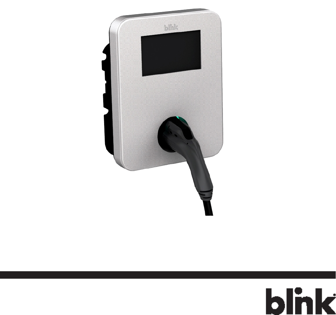
1.1 Product View
Blink IQ 200 - Advanced
Model #:
IQW2-80U-M1-R2-N-25 (80A)
IQW2-32U-M1-R2-N-25 (32A)
Figure 1-1. Advanced Front View
4
Charge on.
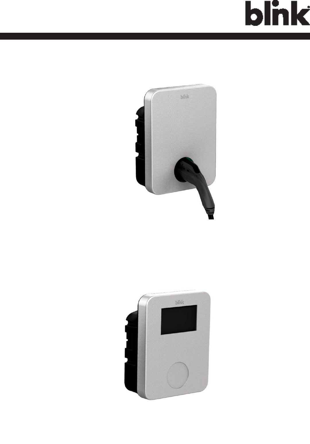
Blink IQ 200 - Smart
Model #:
IQW2-80U-W1-N1-N-25
Figure 1-2. Smart Front View
Blink IQ 200 - Kiosk
Model #:
IQW2-00U-M1-R2-N-00
Figure 1-3. Kiosk Front View

5
Charge on.
2 Specications
2.1 Product Specications
Table 2-1. Product Specications.
Item Specication
Kiosk Advanced (80A) Smart Advanced (32A)
Power Input
Input Rating 120/208/240 V~,
single phase, 60
Hz.
208/240 V~, single phase, 60 Hz.
0.22 A maximum. 80 A maximum. 32 A maximum.
Connections
& Wiring
Uncorded, Hard-Wired, L1, L2, and GND.
Standby
Power
< 10 W. < 10 W. < 5 W. < 10 W.
Power Output
Onput Rating
120/208/240 V~,
single phase, 60
Hz.
208/240 V~, single phase, 60 Hz.
No output. 80 A maximum,
19.2 kW maximum.
32 A maximum,
7.68 kW maximum.
Cold-Load
Pickup
Randomized delay between 120 and 720 seconds before charge resume after a power
failure.
Protection
Internal
Residual
Current
Detection
CCID 20, 20 mA CCID per UL 2231, Automatic and Manual Reset Feature.
Upstream
Breaker
2-pole 100 A (max.) breaker on dedicated circuit, Non-GFCI type.
Plug-Out
Protection
Power output is de-energized when a charging connector is disconnected from an EV.
Electrical
Protection
Over Current, Short Circuit, Over Voltage, Under Voltage, Ground Fault,
Surge Protection, Over Temperature.
Communication
Local Area
Network
(LAN)
10/100 Base T Ethernet LAN.
Wireless
Local Area
Network
(WLAN/
WiFi)
802.11 b/g/n
Cellullar CDMA/UMTS Cellular. None. CDMA/UMTS
Cellular.

6
Charge on.
Item Specication
Kiosk Advanced (80A) Smart Advanced (32A)
User
Interface
& Control
Charger
Status
Indicators -
LDE Status
Indicator
None. LED Status Indicator:
Steady Green = Power On/Ready To Charge.
Flashing Green (Fast) = Vehicle Connected/Ready To Charge.
Flashing Blue (Slow) = Charging.
Flashing Red = Warning/Fault.
Steady Green = Charging Complete.
Display LCD w/Touch Panel. None. LCD w/Touch Panel.
Card Reader RFID/NFC/SCC Reader. None. RFID/NFC/SCC
Reader.
Audible
Feedback
Speaker:
Sound 1 = System Powered/Initialized Successfully.
Sound 2 = Charging Connector Attached To
EV.
Sound 3 = Charging Connector Disconnected From
EV.
Sound 4 = Charge Session Complete.
Sound 5 = Warning/Fault.
Sound 6 = Card/Payment Device Successfully
Read.
Sound 7 = Card/Payment Device Authorized.
Sound 8 = Card/Payment Device Not Autho-
rized.
None.
w/Speaker.
Please refer to left
column for the
dsscription of
different sounds.
Environmental
Operating /
Storage
Temperature
-22°F to 122°F (-30°C to 50°C).
-40°F to 176°F (-40°C to 80°C).
Humidity 0 to 95% relative humidity, non-condensing.
Mechanical
Charging
Cable Length None. 25 ft (7.62 m).
Ingress
Protection NEMA Type 3R (Rainproof).
Mounting
Type Pedestal Mount or Wall-Mount Unit.
Cooling Convection, Natural cooling.
Dimension
(W x H x D) 13.95 x 10.65 x 5.23 inch (354 x 271 x 133 mm).
Net Weight 8.8 lb (4 kg). 25.3 lb (11.5 kg). 24.2 lb (11 kg). 25.3 lb (11.5 kg).

7
Charge on.
Item Specication
Kiosk Advanced (80A) Smart Advanced (32A)
Regulation
Certicate UL
Charging
Interface
None. SAE J1772 compliant charging plug.
Accessibility
Instruction Manual x 1.
Quick Start Guide x 1.
Limited Warranty x 1.
Mounting Bracket x 1.
Srews x 4.
12 AWG Ring Terminals
x 2.
14 AWG Ring Terminals
x 1.
Instruction Manual x 1.
Quick Start Guide x 1.
Limited Warranty x 1.
Mounting Bracket x 1.
Srews x 4.
2 AWG Ring Terminals x 2.
8 AWG Ring Terminals x 1.
Vinyl End Cap (Black) x 1.
Vinyl End Cap (Red) x 1.
Vinyl End Cap (Green) x 1.

8
Charge on.
3 Installation
3.1 Before Installation
3.1.1 Safety Check
CAUTION: DISCONNECT ELECTRICAL POWER PRIOR TO INSTALLING or REPAIR THE BLINK
CHARGER. FAILURE TO DO SO MAY CAUSE PHYSICAL INJURY OR DAMAGE TO THE ELECTRICAL
SYSTEM AND BLINK CHARGING UNIT.
The Blink Charger should be installed only by a licensed contractor, and/or a licensed electrician in accor-
dance with all applicable state, local and national electrical codes and standards.
Before installing the Blink Charger, review this manual carefully and consult with a licensed contractor, li-
censed electrician and trained installation expert to ensure compliance with local building practices, climate
conditions, safety standards, and state and local codes.
Use appropriate protection when connecting to the main power distribution cable. Use tools as outlined in the
section “Tools Required for Installation”.
3.1.2 Grounding Instructions
This product must be connected to a grounded, metal, permanent wiring system; or an equipment grounding
conductor must be run with the circuit conductors and connected to the equipment grounding terminal or lead
on the product.
3.2 Tools & Parts Required for Installation
Table 3-1. Tools & Parts Required for Installation.
Tool Size Supplier
EVSE Mounting Bracket N/A Model Accessories
Torx Bolts (4each) - used to secure the
EVSE to the mounting bracket T20 (On the Model) Model Accessories
Terminal tube Color: Red, Black, Green Model Accessories
Terminal Model Accessories
Conduit – used for power wire 1” Commercially available
Bolts (4 each) – used to secure the
main body mounting braket on the
wall
M8x18 lag bolts with lock wash-
ers Commercially available
Torx Driver T20 Commercially available
Slotted Screwdriver Commercially available
Philips Screwdriver PH3 Commercially available
Bolts (for masonry) M8, expansion Commercially available
Torque Wrench Commercially available
Wire, Copper No. 8 AWG, 75°C or 90°C Commercially available

9
Charge on.
3.3 Install the Charger
1. Drill bolt holes in the wall for the mounting bracket.
Note: Follow applicable accessibility requirements for the mounting position. The unit shall be mounted at
a sufcient height from ground such that the height of the storage means for the coupling device is located
between 24 inches (600 mm) and 4 feet (1.2 m) from ground per NEC Article 625.
Masonry Walls Sheet Rock and Wood Stud Walls
Figure 3-1. Mounting Bracket
2. Secure the main body mounting bracket to the wall with appropriate bolts, as follows:
a. For masonry walls, use M8 expansion bolts.
b. For nished walls supported by wood studs, use M8x18mm lag bolts with lock washers.
10
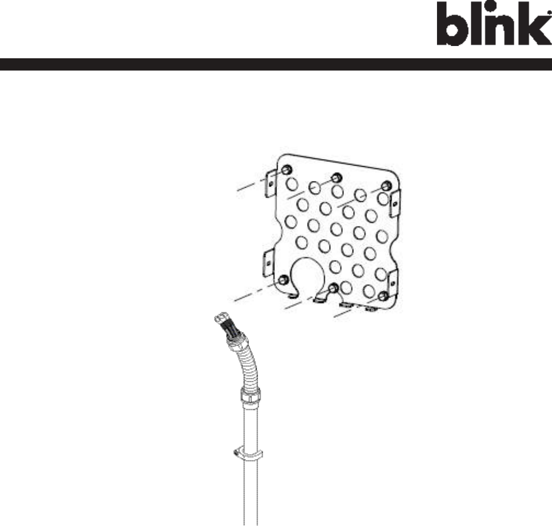
Charge on.
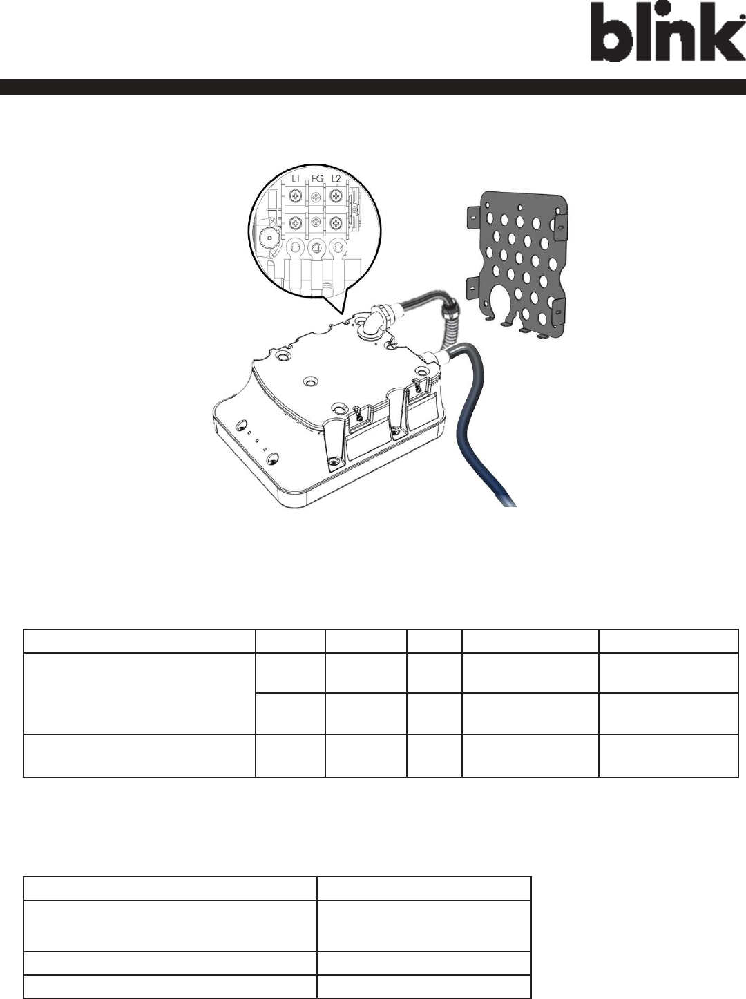
Figure 3-2. Prepare for Wiring.
3. Connect the electrical wiring to the Blink Charger.
3-1. Choose the appropriate conduit in accordance with all applicable state, local and national electrical codes
and standards.
11
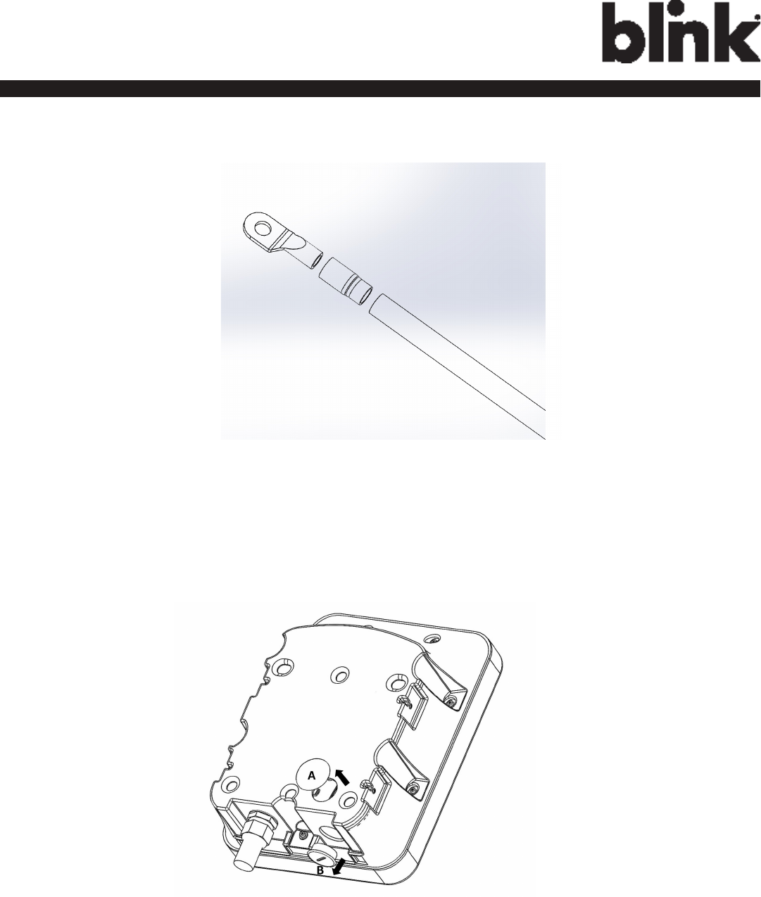
Charge on.
Figure 3-3. Terminal tube.
3-2. Clamp the Terminal, Terminal tube and Copper wire (Red is for L1, Black is for L2)
Figure 3-4. Remove the cover.
3-3. Remove the plug cover (A or B) and use slotted screwdriver (if required)
12
Charge on.
Figure 3-5. Wiring
3-4. Please use following wire and torque force when connecting to input terminal block. using conductor
type other than RHH, RHW and RHW-2 with outer covering.
Model Terminal Conductor Screw Rating Torque - lb-in (N-m)
IQW2-80U-M1-R2-N-25 (Ad-
vanced) IQW2-80U-W1-N1-
N-25 (Smart) IQW2-32U-M1-R2-
N-25 (32A)
L1, L2 2 AWG M8 90C, copper wire 97.4 (11)
G8 AWG M6 60C, copper wire 70.8 (8)
IQW2-00U-M1-R2-N-00 (Kiosk) L1, L2,
G
14 AWG M4 60C, copper wire 7.1 (0.8)
CAUTION: “To reduce the risk of the re, connect only to a circuit provided with (@) amperes maximum
branch circuit overcurrent protection in accordance with the National Electrical Code, ANSI/NFPA 70, and
the Canadian Electrical Code, Part I, C22.2”.
Model Current Rating
IQW2-80U-M1-R2-N-25 (Advanced)
IQW2-80U-W1-N1-N-25 (Smart)
100 A
IQW2-32U-M1-R2-N-25 (32A) 40 A
IQW2-00U-M1-R2-N-00 (Kiosk) 15 A
13
Charge on.
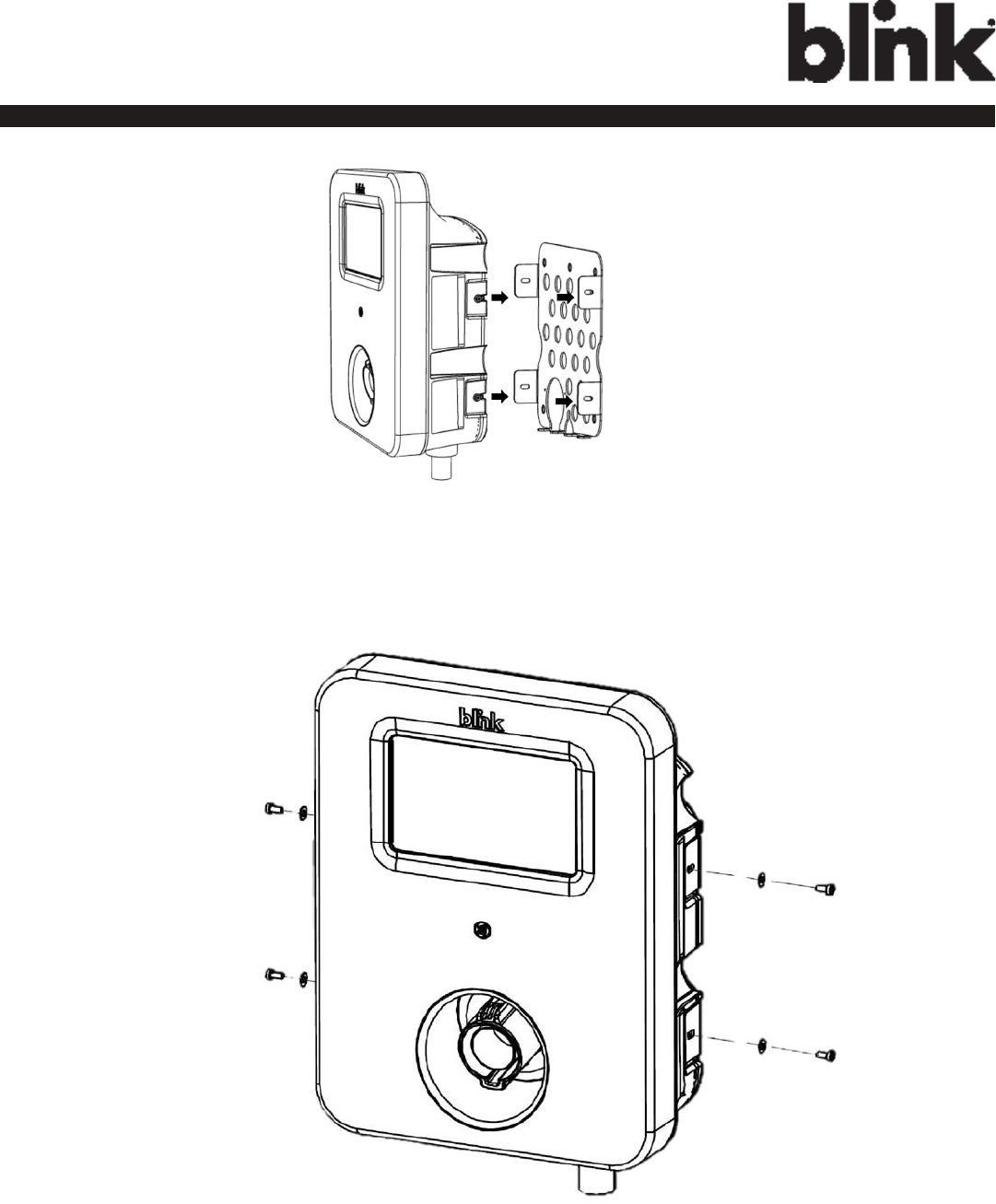
Figure 3-7. Mounting Bracket Screws.
5. Install and secure with four screws to the mounting bracket. (Use a torque force of 1.5 newton metre)
Figure 3-6. Blink Charger and Mounting Bracket
4. Align the screw holes of the mounting bracket with the Blink charger holes.(Use a torque force of 1.5 newton
metre.)
14
Charge on.
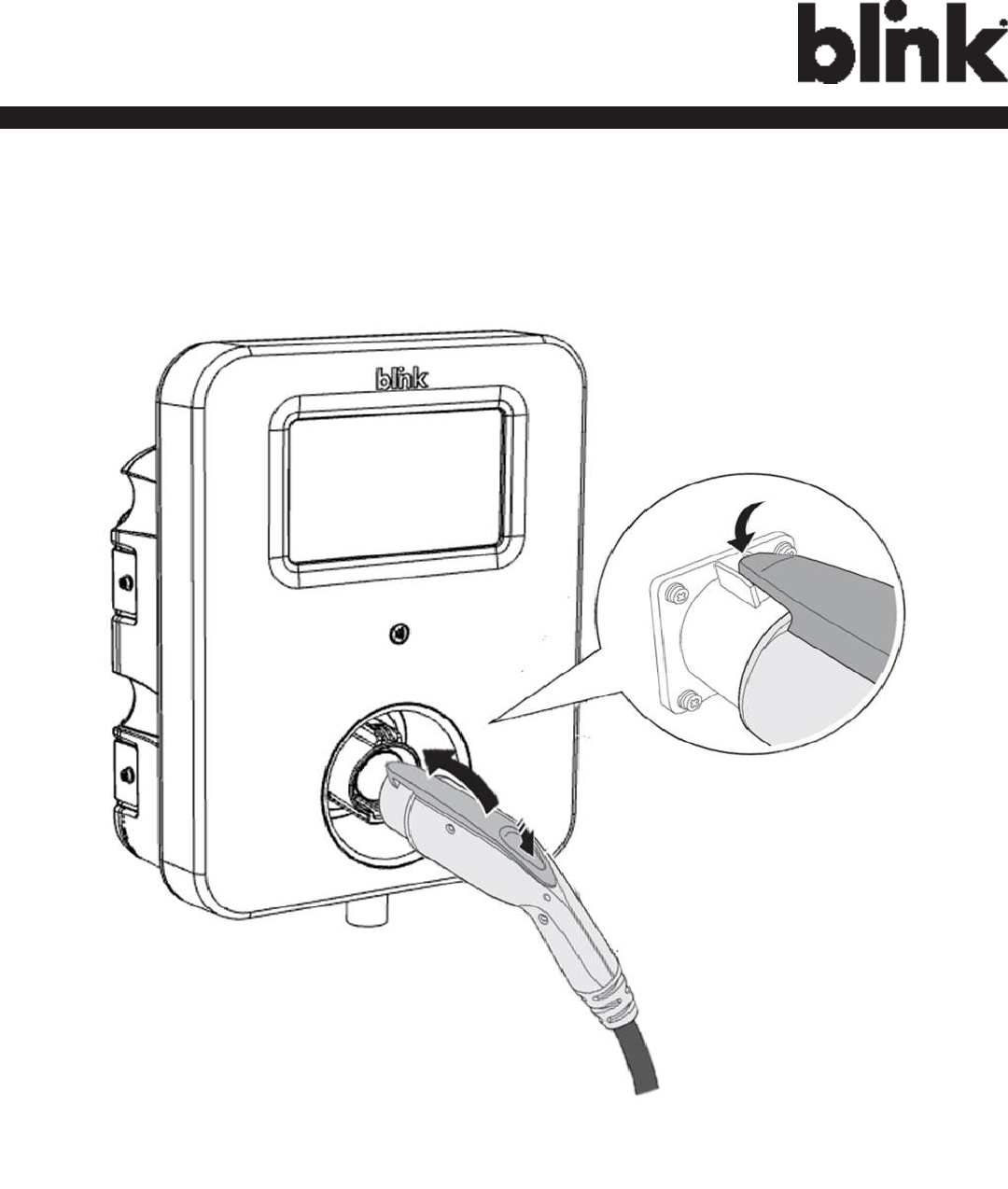
Figure 3-8. Blink Charger and Charger Plug.
15
Charge on.
4 Web Portal Login
Instructions
4.1 Getting Started
4.1.1 Setting Up the Local Network
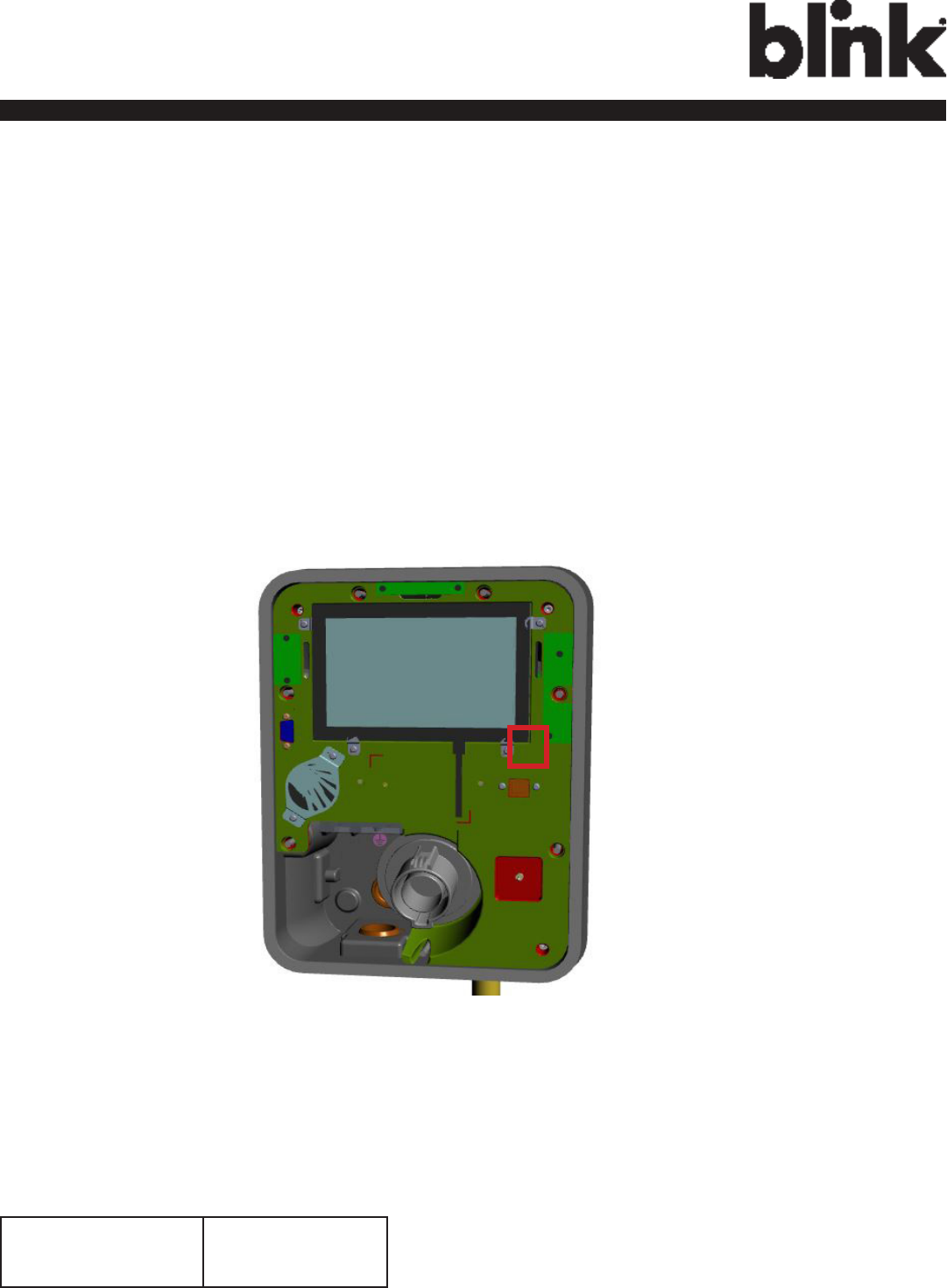
Firstly, connect a computer to the charge point using an Ethernet cable. There is an
Ethernet RJ-45 port in the Blink Charger for connecting.
Figure 4-1. Ethernet RJ-45 Port location.
Secondly, set up a Static IP Address on your computer (except 169.254.63.255, cause
it’s the default IP of Blink Charger.
Enter the IP
address
169.254.xxx.
xxx

16
Charge on.
4.1.2 Log In
Open a web browser (Internet Explorer for example) and enter the default IP of Blink
Charger (169.254.63.255) in the address eld of the browser and press enter.
http://169.254.63.255/
Now you should see the login screen:
To be able to congure the charge point you should enter “admin” in the user-name box.
The default password for each unit should be different to enhance security.
It will be 11-character format (YYWW-SSSSSS) subtracted from ChargePointSerialNumber.
e.g. 1627-000001
17
Charge on.
4.2 Web-page Overview
4.2.1 Menu Overview
There are ve menu items available on the Web-page: Conguration, Maintenance, LLM
Status, and Security.
4.2.2 Conguration Menu
When you choose the Conguration menu, a sub menu will appear:
The “Factory Settings” tab is used to display the information of the charge point.
The “Commissioning
Settings” tab
is used to set up the charge point to use the OCPP services.
18
Charge on.
4.2.3 Maintenance Menu
When you choose the Maintenance menu, a sub menu will appear:
The “Command” screen can be used to restart the charge point and reset settings
to MFG default.
The “Firmware Upgrade”
screen
can be used to upgrade the rmware of the charge
point.
4.2.4 LLM Status Menu
When you choose the LLM Status menu, a sub menu will appear:
19
Charge on.
4.2.5 Security Menu
When you choose the Security menu, a sub menu will appear:
The “Change Password”
screen
can be used to change the default
password.
4.2.6 Operation Hours Menu
When you choose the Operation Hours menu, a sub menu will appear.
20
Charge on.
4.2.7 Default Price Menu
When you choose the Default Price menu, a sub menu will appear.
The “Default
Parking Price”
screen
shows the Default Parking Price. Default Parking Price could be
modied here or recovery to default setting.
The “Default
Usage Price”
screen
shows the Default Usage Price. Default Usage Price could be
modied here or recovery to default setting.
4.2.8 OQC Test Menu
When you choose the OQC Test menu, a sub menu will appear.
21
Charge on.
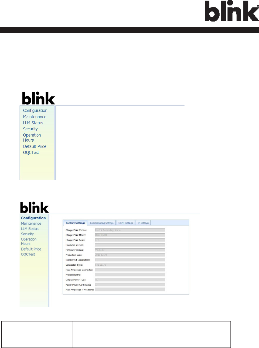
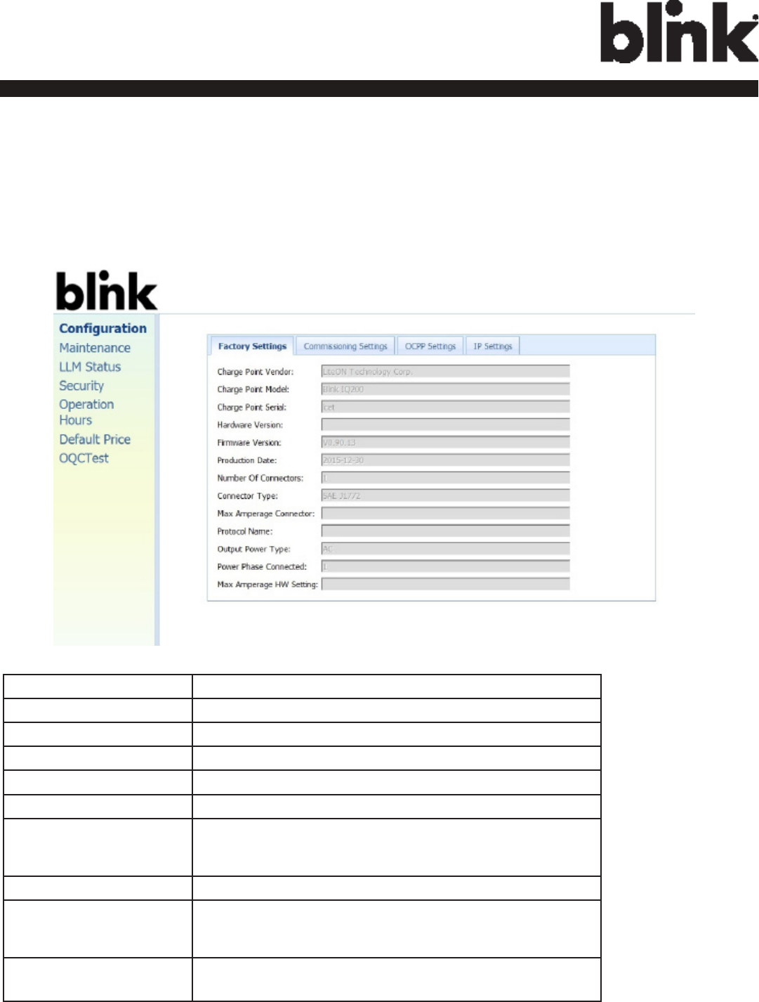
4.3 Conguration
4.3.1 Factory Settings
Clicking on the “Conguration” and then “Factory Settings” link will bring up the
following screen:
Charge Point Vendor The name of the charge point vendor.
Charge Point Model The model of the charge point.
Charge Point Serial The unique serial number of the charge point.
Hardware Version The hardware version of the charge point.
Firmware Version The software version of the charge point.
Production Date The date when the charge point is made.
Number Of
Connectors
Number of connectors of the charge point.
Connector Type Type of the output cable connector.
Max Amperage
Connector
The maximum current output for the charge
point.
Protocol Name The communication protocol between charge point and
BOS.
22
Charge on.
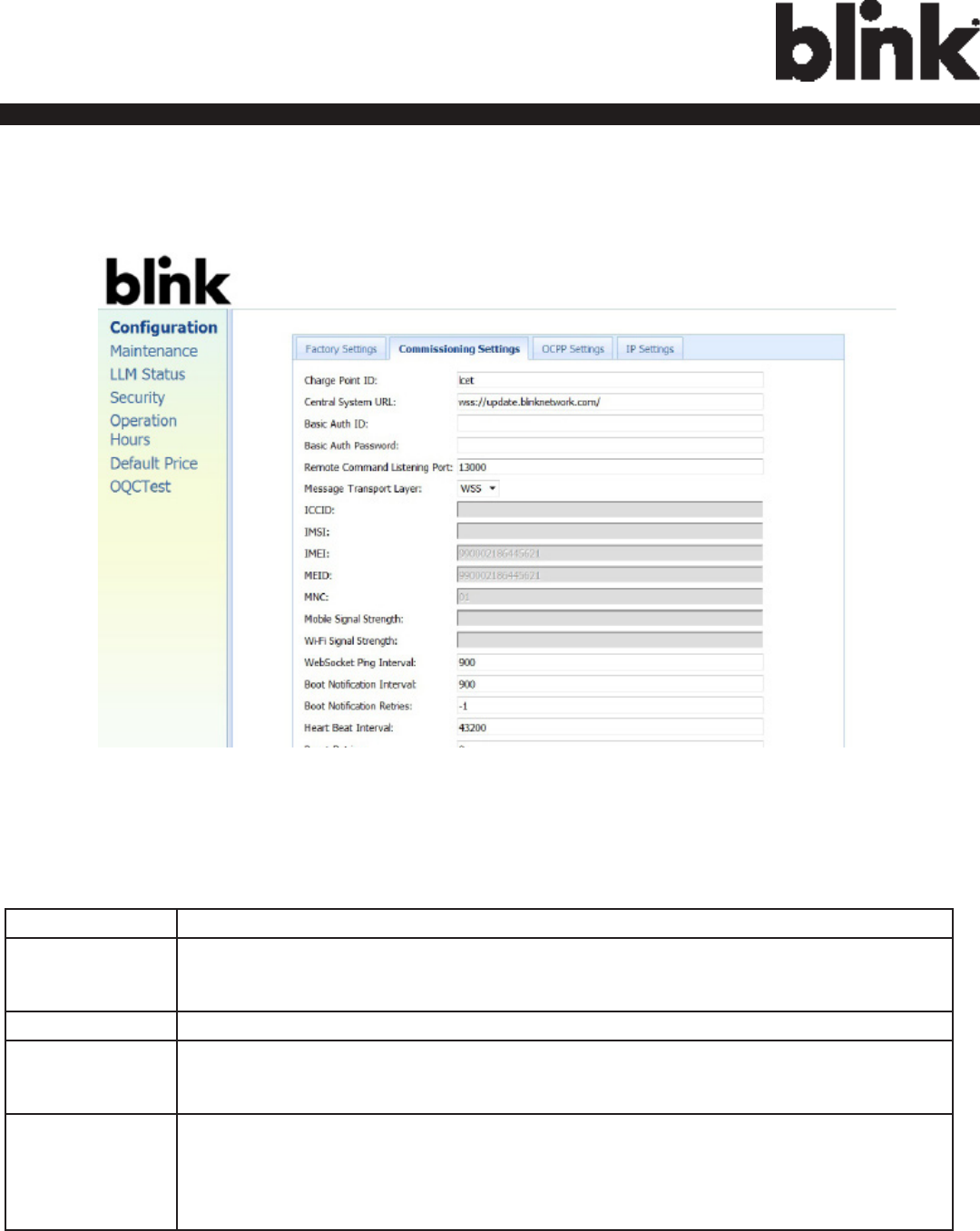
4.3.2 Commissioning Settings
Clicking on the “Conguration” and then “Commissioning Settings” link will bring up
thefollowing screen:
On this page you can change the properties of lQ-200. Click the “Apply” button when the
value is changed.
Charge Point ID The identity of the charger as known in the OCPP Central System.
Central System
URL
The URL of the OCPP Central System service.
Basic Auth ID The ID for BASIC authentication in HTTPS (SSL/TLS) connections.
Basic Auth
Password
The password for BASIC authentication in HTTPS (SSL/TLS) connections.
Remote
Command
Listening Port
The listening port for remote command of the OCPP Central System service.
This property is used only for OCPP SOAP version. The default listening port is
13000.

23
Charge on.
ICCID The ICCID of the modem’s SIM card.
IMSI The IMSI of the modem’s SIM card.
IMEI IMEI code for UMTS mobile system. e.g. 356938035643809.
MEID MEID code for CDMA mobile system. e.g. A0123456789012.
MNC The Mobile Network Code of cellular service provider.
Mobile Signal Strength Signal strength of mobile network. Unit in “dBm”.
Wi-Fi Signal Strength Signal strength of Wi-Fi network. Unit in “dBm”.
WebSocket Ping
Interval
Denes the webSocket ping interval. Unit in “seconds”.
Boot Notication
Interval
Denes the boot notication interval. Unit in “seconds”.
Boot Notication
Retries
Denes the boot notication retry times.
Heart Beat Interval Denes the heartbeat interval. Unit in “seconds”.
Reset Retries Denes the reset retry times.
Download Firmware
Interval
Denes the download rmware interval. Unit in “seconds”.
Download Firmware
Retries
Denes the download rmware retry times.

24
Charge on.
Max Amperage FW Setting Max Amperage allow base on FW design.
Cold Load Pickup Max
Delay
Default cold load pickup delay is 120s ~ 720s.
The max value could be changeable (between 120 ~ 720) by this
property.
EV Connect Timeout Interval (from successful authorization) until incipient charging session
is automatically cancelled due to failure of EV user to (correctly) insert
the charging cable connector(s) into the appropriate socket(s). Unit in
“seconds”.
Plug And Charge ID If the value is present, Charge Point needs to support plug and charge
scenario by using the specic identier. If absent, authorization for each
session is required.
Ofine Authorization Select if the ofine authorization should be enabled or disabled.
Authorize Timeout Max time interval in seconds between presenting RFID-card and
connecting an EV.
Temperature Low Value in Celsius at which the charger will send a temperature low
warning message.
Temperature High Value in Celsius at which the charger will send a temperature high
warning message.
Voltage Low Value at which the charger will send an under voltage warning
message.
Voltage High Value at which the charger will send an over voltage warning message.
Over Current Value at which the charger will send an over current warning message.
Over Current Retries Denes the over current recovery retry times.

25
Charge on.
Dim Option Indicate the timing to turn off LCD backlight. Valid options are:
1) Never (default).
2) 1 (minutes).
3) 2 (minutes).
4) 3 (minutes).
5) 4 (minutes).
6) 5 (minutes).
7) 10 (minutes).
Dim Intensity The percentage of the backlight when DimOption is enabled. Unit in %.
UMTS Dialnumber Dial-in number to access UMTS mobile network (e.g. AT&T).
UMTS Apn Name APN name to access UMTS mobile network (e.g. AT&T).
UMTS Apn User APN user name to access UMTS mobile network (e.g. AT&T).
UMTS Apn Password APN user password to access UMTS mobile network (e.g. AT&T).
CDMA Dialnumber Dial-in number to access CDMA mobile network (e.g. Verizon).
CDMA Apn Name APN name to access CDMA mobile network (e.g. Verizon).
CDMA Apn User APN user name to access CDMA mobile network (e.g. Verizon).
CDMA Apn Password APN user password to access CDMA mobile network (e.g. Verizon).
Fallback Amperage The fallback charging current when a Charge Point is ofine, no matter
in Standalone / Primary Secondary modes. Unit in “A”.
Resume Charging Indicate if Charge Point resumes charging after power recycle. If true,
Charge Point will resume charging according to UL regulations. If false,
Charge Point will not resume charging according to CCGI’s scenario.
Default is false.
Interanl Settings
RFID Reader Select if the RFID service should be enabled or disabled.
Continue Charging Select whether to resume charging after power outage.
26
Charge on.
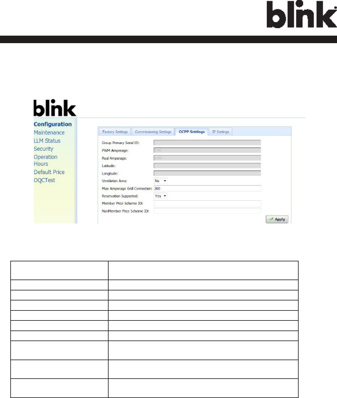
4.3.3 OCPP Settings
Clicking on the “Conguration” and then “OCPP Settings” link will bring up the following
screen:
Group Primary Serial ID The charge box serial number of Primary in the group if
it’s LLM enabled.
PWM Amperage The amperage used by PWM shown to EV.
Real Amperage The real-time measured amperage of charger.
Latitude Latitude of the location.
Longitude Longitude of the location.
Ventilation Area Show if charge point installed in ventilation required area.
Max Amperage Grid Connection Maximum current of the input power source grid.
Reservation Supported If true, Charge Point will support reservation related messages from
Central System.
Member Price Scheme ID The default price scheme ID will be used for Blink members when a
Charge Point is ofine.
Non Member Price Scheme ID The default price scheme ID will be used for NON Blink members
when a Charge Point is ofine.
27
Charge on.
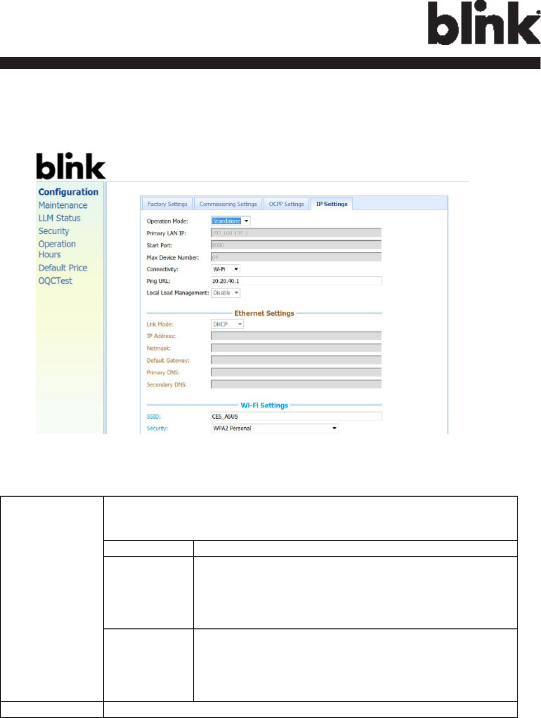
4.3.4 IP Settings
Clicking on the “Conguration” and then “IP Settings” link will bring up the following
screen:
On this page you can set up the network connection. To nish, click the “Apply” button.
Operation Mode Species if enable the Local Proxy function. Available options are Standalone,
Primary and Secondary. The Combo box will be disabled if your charge point
does not support this function. And Device Mode will be set as Standalone.
Standalone Use charge point as a single device.
Primary Use charge point as a primary charge point. Primary con-
nected to OCPP Server via 3G and connected to other charge
points (Called Secondary) via Wi-Fi and forms a local charge
points group. This group is also a WLAN (Wireless Local
Area Network).
Secondary Use charge point as a Secondary charge point. Second-
ary connected to Primary via Wi-Fi. Secondary connected
to OCPP Server through Primary charge point (via 3G) and
Primary will dispatch incoming remote command to proper
Secondary charge points (or Primary itself).
Primary LAN IP The IP of primary in LAN. This value cannot be modied by users.

28
Charge on.
Max Device Num-
ber
The maximum number of charge points allowed in a group/LAN. This value
cannot be modied by users.
Connectivity Species whether the charge point should always be connected to Internet
using Auto, Ethernet, or 3G. Default value is Auto.
Ping URL Address of the host that the charge point will ping for the Ethernet
connection. This value will automatically set to the address of “Server URL”.
Local Load
Management
Enable or Disable local load management function. This function can only be
enabled in a primary charge point.
HINT: If user changes “Device Mode” setting, then related settings will also change automatically
such as “Connectivity”, “Local Load Management”. The default value is as follow:
Standard Alone Primary Secondary
Primary LAN IP Not used Default value, not changeable Not used
Start Port Not used Default value, not changeable Not used
Max Device Number Not used Default value, not changeable Not used
Connectivity Auto 3G, not changeable Wi-Fi, not changeable
Ping URL User setting User setting User setting
Local Load Management Disable, not changeable Enable Enable
4.3.4.1 Ethernet Settings
Link Mode Congure the Ethernet port to use DHCP or Static IP. If you select Static IP from
the dropdown menu, you need to enter values for IP Address, Netmask, and
Default Gateway elds.
IP Address The IP address of the charge point.
Netmask The subnet mask.
Default
Gateway
The default gateway.
Primary DNS The primary Domain Name Server (optional).
Secondary DNS The secondary Domain Name Server (optional).
29
Charge on.
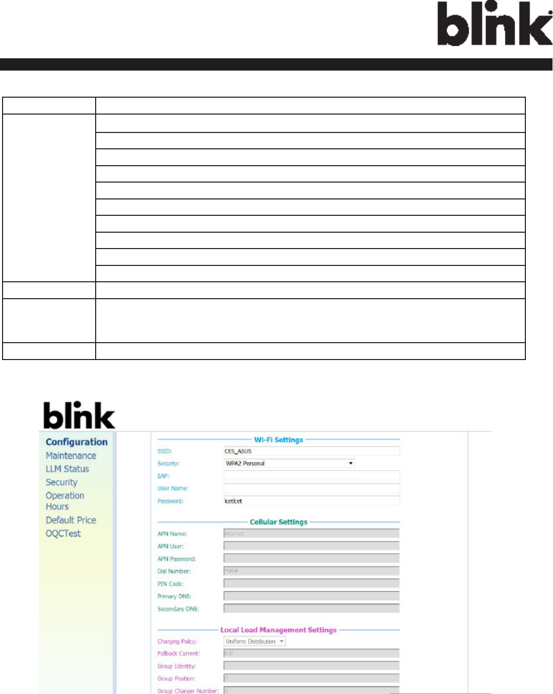
4.3.4.2 Wi-Fi Settings
SSID SSID name to access Wi-Fi network (WAN).
Security Security methods to access Wi-Fi network (WAN). Possible options are:
1) NONE
2) WPA_PERSONAL
3) WPA_ENTERPRISE
4) WPA2_PERSONAL
5) WPA2_ENTERPRISE
6) WEP
7) IEEE8021X
8) WPA2_PERSONAL_SHA256
9) WPA2_ENTERPRISE_SHA256
EAP Mandatory for the following security: IEEE8021X.
User Name Mandatory for the following security:
WPA_ENTERPRISE, WPA2_ENTERPRISE, IEEE8021X, WPA2_ENTERPRISE_SHA256.
Password SSID password to access Wi-Fi network (WAN).

30
Charge on.
4.3.4.3 Cellular Settings
APN Name This is the gateway for all 3G trafc. Contact your 3G operator for
information about this.
APN User This is the user name your ISP has assigned to you (optional).
APN Password Password to log into the ISP network (optional).
Dial Number Phone number to dial.
PIN Code PIN code for the modem’s SIM card (optional).
Primary DNS The primary Domain Name Server (optional).
Secondary DNS The secondary Domain Name Server (optional).
4.3.4.4 Local Load Management Settings
Charging Policy The charging policy for LLM primary to decide the charging current for
each charger.
Valid options are:
1) UD
(default)
Uniform Distribution. The max. Amperage is divided by
total numbers of charging EV, i.e. each EV will use the same
charging current.
2) FIFS First In First Serve.
Fallback Current The fallback current when Secondary is not able to communicate with
Primary. Primary will overwrite fallback current in Secondary with its own
value when Secondary connected to Primary.
Group Identity An identity of the LLM group. A Secondary with different group identity
will be rejected when attempting to connect to Primary.
Group Position The physical position order of the charger in the LLM group.
Group Charger
Number
The total number of chargers in the LLM group. This value is only used in
Primary.
31
Charge on.
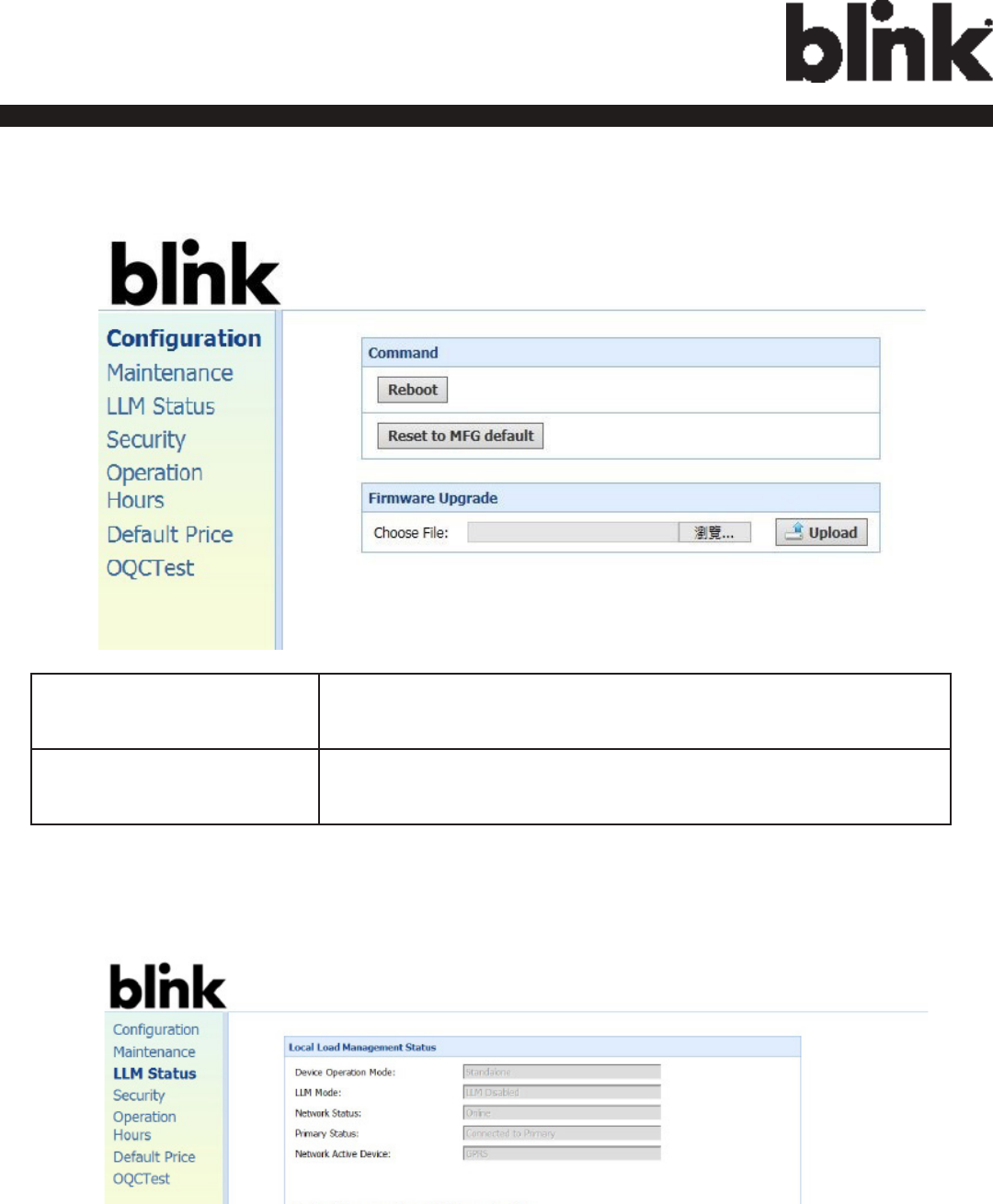
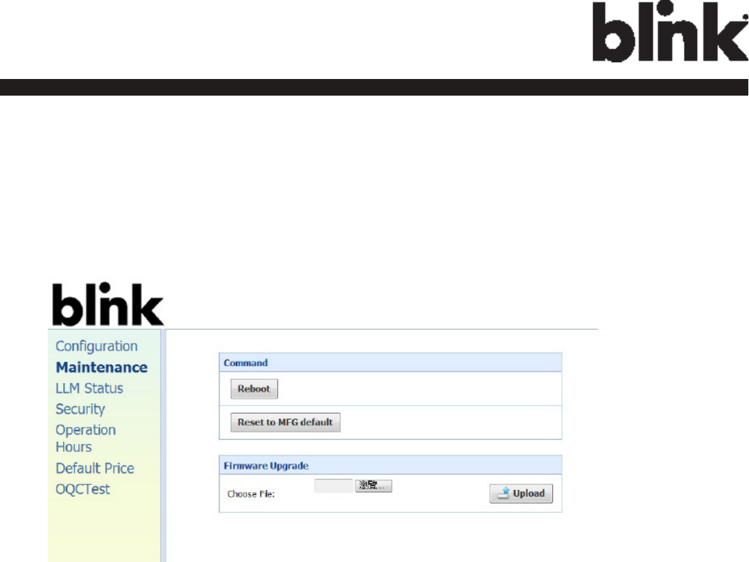
4.4 Maintenance
4.4.1 Command
To restart the charge point, click the “Reboot” button.
To reset the MFG default, click the “Reset to MFG default” button.
4.4.2 Firmware Upgrade
To upgrade the rmware of the charge point, you need to download the upgrade
image le to your local hard disk, and then click the “Choose File” button to locate
the rmware le on your computer. Once you have selected the new rmware le,
click the “Upload” button to start the upgrade process.
32
Charge on.
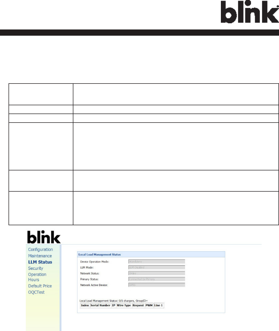
4.5 LLM Status
4.5.1 LLM Information
This page shows the Local Load Management information of the charge point.
Device Operation
Mode
Indicates the charger is in Standalone mode, a Primary or a
Secondary.
LLM Mode Indicates LLM function is enabled or disabled.
Network Status Indicates if the charger is online or not.
Primary Status Indicates if the charger is connected to the Primary if it’s a
Secondary.
For Standalone and Primary, it always shows “Connected to
Primary”.
Network Active
Device
Indicates the Network connected via which device. It could be
Ofine, Ethernet or 3G.
Local Load
Management Status
Display connected chargers, total chargers, Group ID of the LLM
group as well as a full table of detail information each charger if
this charger is Primary.
4.5.2 Primary/Secondary Group Table
If the charge point is Master, the following LLM Group Table is present.
33
Charge on.
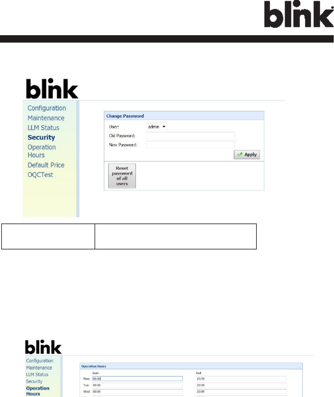
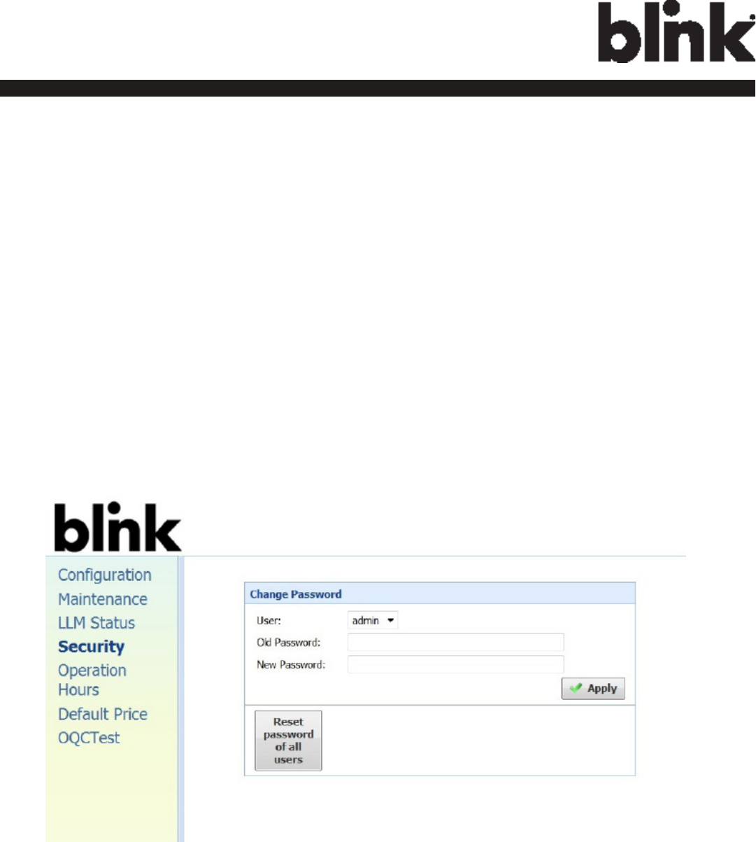
4.6 Security
4.6.1 Change Password
To change password, rst choose user you want to change password. There are two
default users –
admin and maintain.
Only admin user can access Security Page.
Enter old password and new password then press “Apply” button to change password of
the user.
To reset password of all users, press “Reset password of all users” button.
34
Charge on.
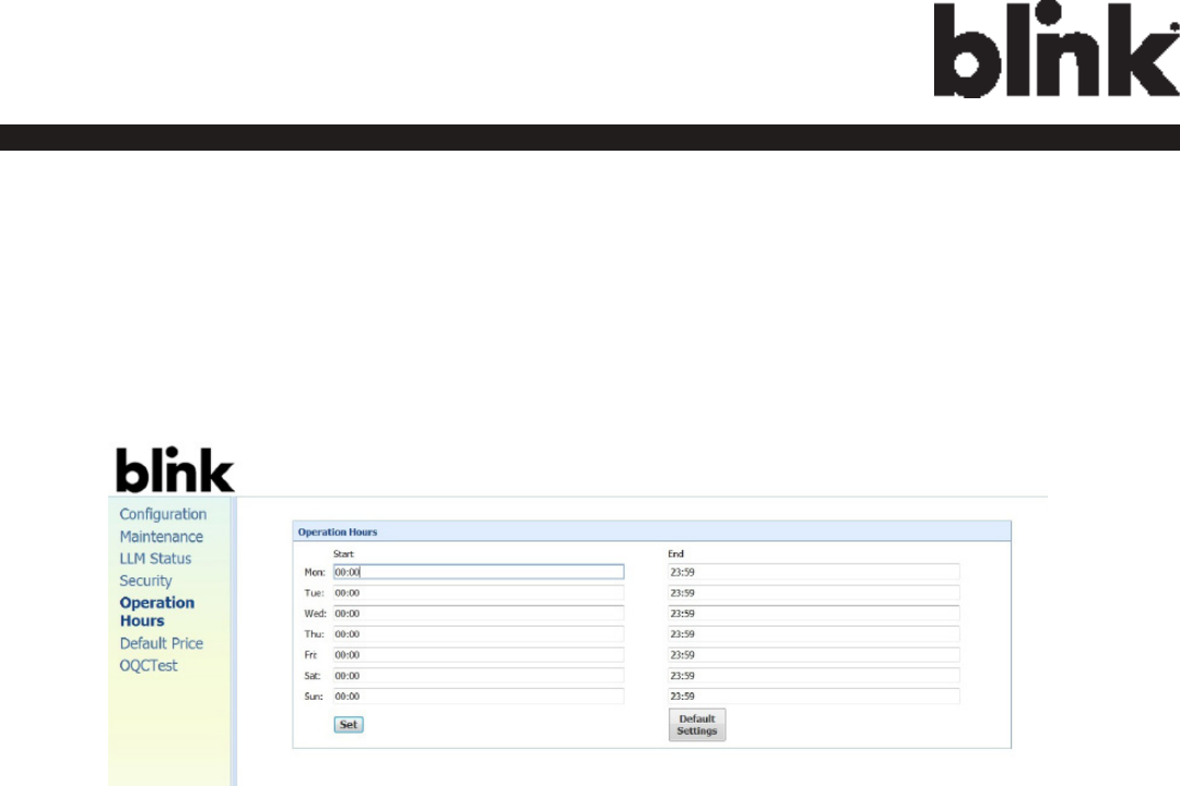
4.7 Operaon Hours
4.7.1 Operation Hours
The “Operation Hours” screen shows the Operation Hour Setting of the whole Weekly.
Operation Hour could be modied here or recovery to default setting.
35
Charge on.
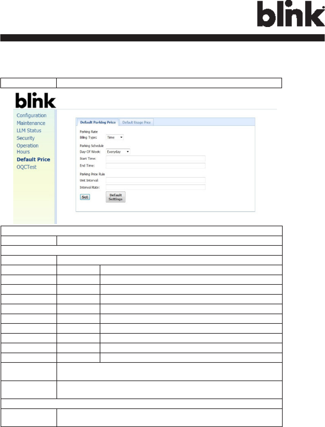
4.8 Default Price
4.8.1 Default Parking Price
Parking Rate
Billing Type Billing type, e.g. per time, per session or per kWh.
Parking Schedule
Day of Week Indicate the Day O fWeek.
Monday Based on ISO8601, Monday is the rst day of week.
Tuesday Based on ISO8601, Tuesday is the second day of week.
Wednesday Based on ISO8601, Wednesday is the third day of week.
Thursday Based on ISO8601, Thursday is the fourth day of week.
Friday Based on ISO8601, Friday is the fth day of week.
Saturday Based on ISO8601, Saturday is the sixth day of week.
Sunday Based on ISO8601, Sunday is the seventh day of week.
Weekday Include Monday, Tuesday, Wednesday, Thursday and Friday.
Weekend Include Saturday and Sunday.
Everyday Every day.
Start Time The start time of this schedule. It is always a 4-digit string, formatted HHMM. If it is
null, startTime is “00:00”.
End Time The end time of this schedule. It is always a 4-digit string, formatted HHMM. If it is
null, endTime is “23:59”. The endTime SHALL be larger than startTime.
Parking Price Rule
Unit Interval The interval rate to be captures like per kwh, per 30 seconds etc. In this example
interval rate is 1800 seconds.
Interval Rate The base rate of EVSE to be applied for current pricing rule schedule entry.
36
Charge on.
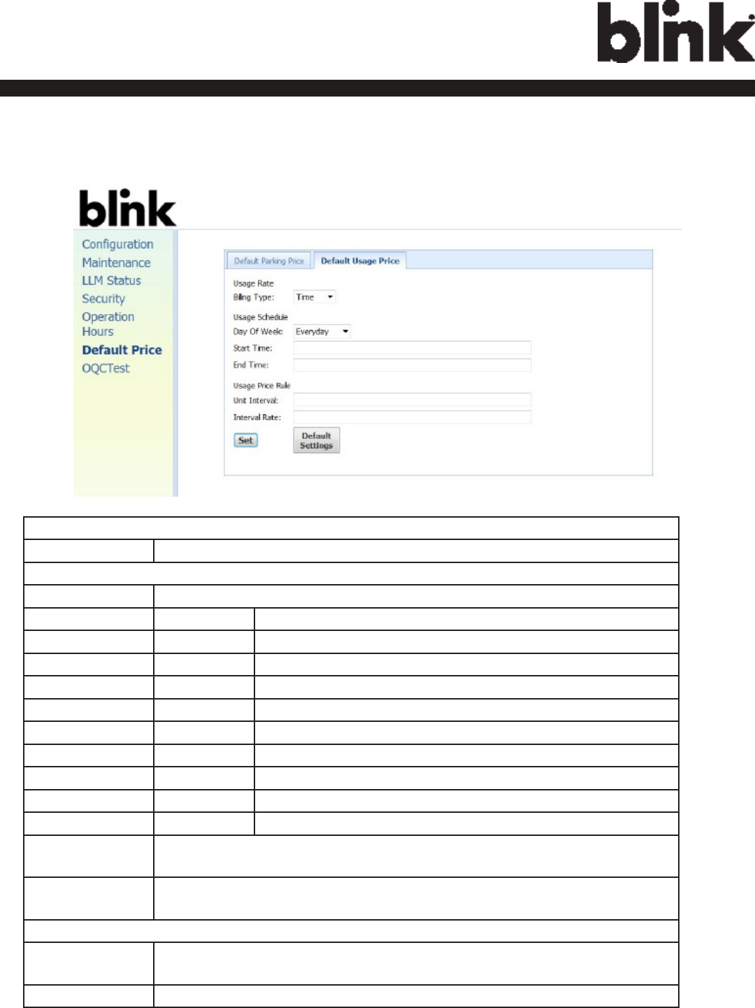
4.8.2 Default Usage Price
Usage Rate
Billing Type Billing type, e.g. per time, per session or per kWh.
Usage Schedule
Day of Week Indicate the Day O fWeek.
Monday Based on ISO8601, Monday is the rst day of week.
Tuesday Based on ISO8601, Tuesday is the second day of week.
Wednesday Based on ISO8601, Wednesday is the third day of week.
Thursday Based on ISO8601, Thursday is the fourth day of week.
Friday Based on ISO8601, Friday is the fth day of week.
Saturday Based on ISO8601, Saturday is the sixth day of week.
Sunday Based on ISO8601, Sunday is the seventh day of week.
Weekday Include Monday, Tuesday, Wednesday, Thursday and Friday.
Weekend Include Saturday and Sunday.
Everyday Every day.
Start Time The start time of this schedule. It is always a 4-digit string, formatted HHMM. If it is
null, startTime is “00:00”.
End Time The end time of this schedule. It is always a 4-digit string, formatted HHMM. If it is
null, endTime is “23:59”. The endTime SHALL be larger than startTime.
Usage Price Rule
Unit Interval The interval rate to be captures like per kwh, per 30 seconds etc. In this example
interval rate is 1800 seconds.
Interval Rate The base rate of EVSE to be applied for current pricing rule schedule entry.
37
Charge on.
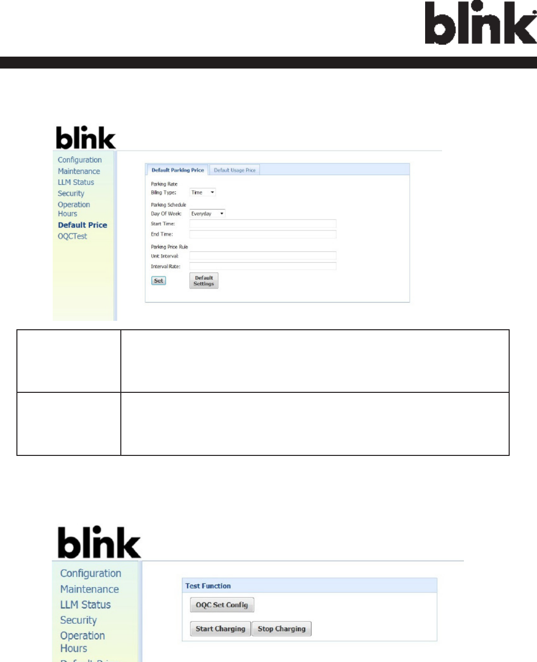
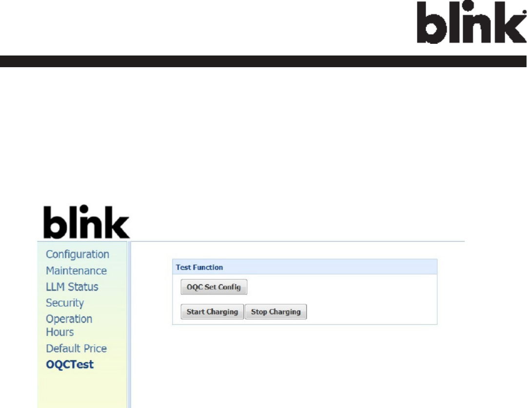
4.9 OQC Test
4.9.1 Test Function
This page shows some functions for internal or quality department testing use.
We recommend that users do not try to use any of the functions here.

38
Charge on.
5 Operations
5.1 About the Charger
5.1.1 Charging Status Indicators
Table 5-1. Charging Status Indicators.
Charger Plug
LED Indicator DESCRIPTION
DEFINITION
Not illuminated Charger is powered OFF.
Steady Green
Charger is powered ON / Ready for charging
/ Charge Complete.
Flashing gGeen
(Fast)
Flashing green (Fast) = Vehicle Connected / Ready
for charging.
Flashing Blue
(Slow) Flashing blue (Slow) = Charging in process.
Flashing Red Warning / Fault.
Steady Yellow Charger booting.
Flashing Yellow Firmware Upgrading.
39
Charge on.
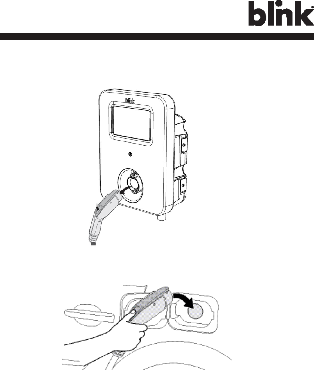
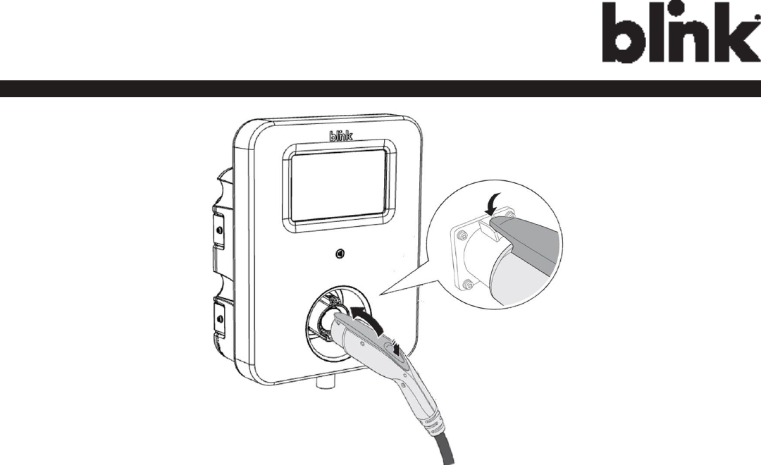
5.2 Charging an Electric Vehicle (EV)
1. Release the charging plug from the charger holster and connect it to the EV.
Figure 5-1. Remove the Charging Plug from the Charger Holster.
Figure 5-2. Connect the Charging Plug to the EV.
2. Insert the charging plug into the EV
40
Charge on.
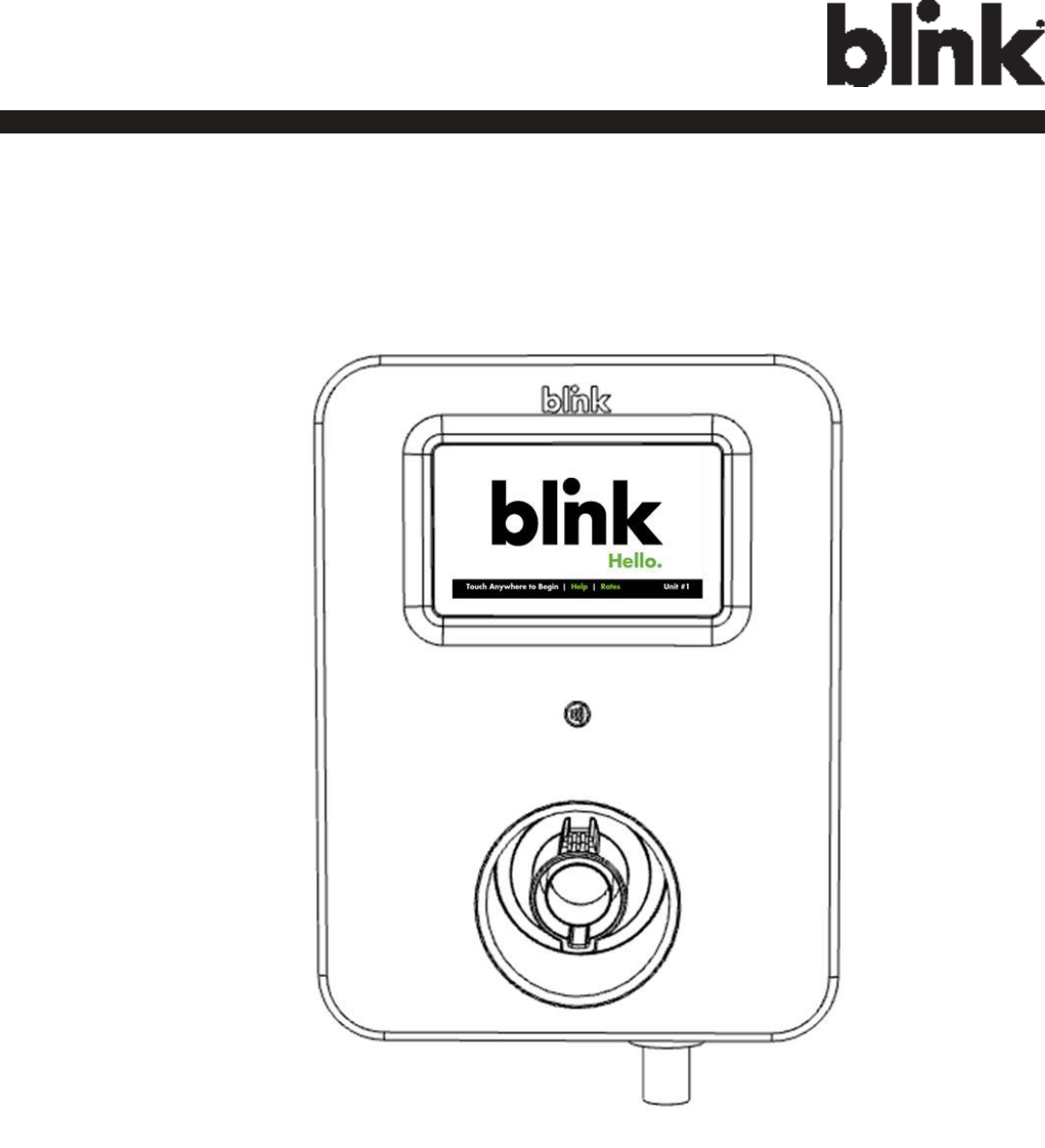
3. Go to Blink Charger, and to follow the instruction shown on the screen
Figure 5-3. Blink Charger screen.
41
Charge on.
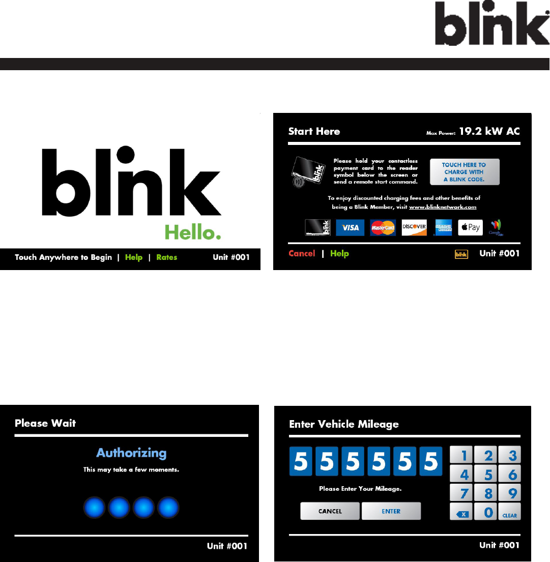
Figure 5-3. Blink Charger screen.
2. SWIPE CARD
1. START CHARGING
Touch anywhere of the screen to
begin.
4. ENTER VEHICLE
MILEAGE
3. WAITING FOR
AUTHORIZING
42
Charge on.
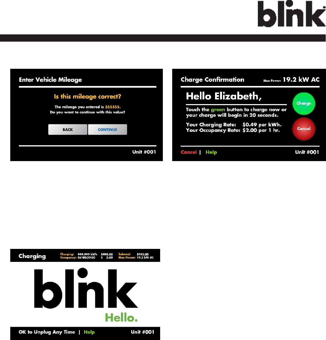
5. DOUBLE CONFIRM THE
MILEAGE
Press “CONTINUE” to the next
page.
6. CHARGE
CONFIRMATION
7. CHARGING SESSION
STARTED
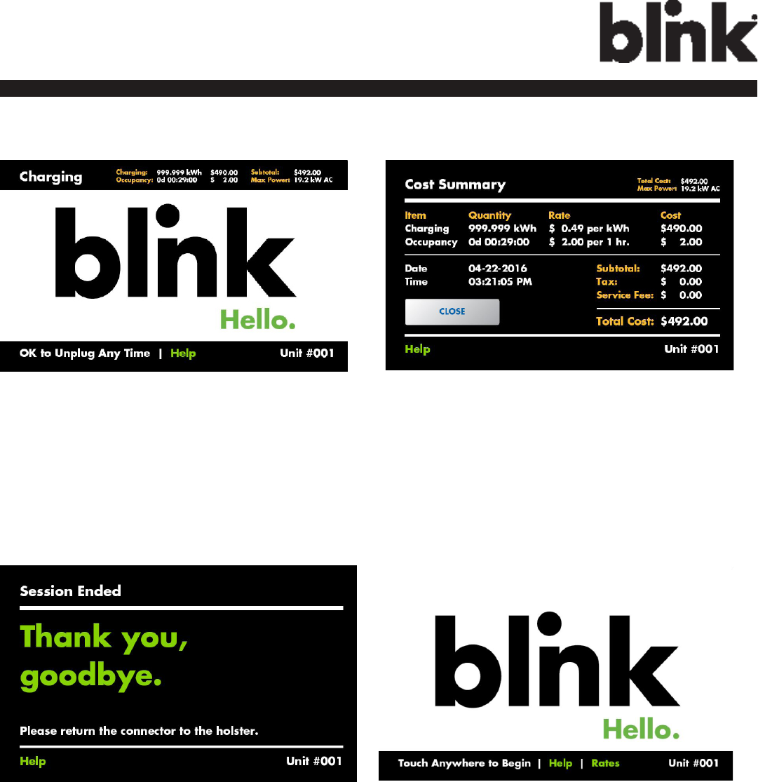
43
Charge on.
1. UNPLUG ANY TIME
Disconnect the charging plug
from EV to stop charging
session.
2. READ COST
SUMMARY
Read the cost summary and
then press “CLOSE”.
4. GO BACK TO THE
MAIN SCREEN
3. SESSION ENDED
Please return the connector to
the holster and touch anywhere
of the screen.
5.3 Stop Charging
44
Charge on.
Figure 5-4. Place the Charging Plug into the Charger Holster.
5.3.1 Interrupt Charging
Please refer to STOP CHARGING section for more information.
5.3.2 Auto Restart
When a charging session is interrupted due to a temporary error condition, the Blink Charger will automatically
restart charging when the cause of the temporary error condition returns to normal. Status indicator lights remain
ashing RED until the error condition is resolved.
• Temporary error conditions include: Over Current, Over Voltage, Under Voltage, Over Temperature.
• For Over Current conditions: The charging seesion will be stop while OC occurs. After recovery from OC
for 30 seconds, Blink Charger will automatically restart charging for three times.
• When charging session stopped due to CCID trip, Blink Charger will try to restart after 15 minutes for 3
times.
5.3.3 Power Outage Recovery
When power resumes after an outage, the Blink Charger restarts automatically with a delay ranging from 120 to
720 seconds. The delay is designed to avoid impacting the utility grid when multiple chargers are in the same area
attempting to resume charging simultaneously.
45
Charge on.
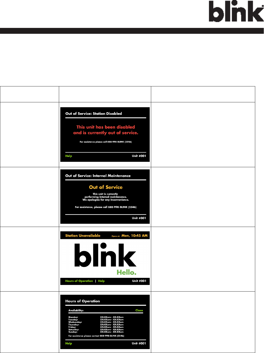
SITUATION
Screen Displayed ACTION
Out Of Service (Sta-
tion Disable)
1. Station Disabled.
2. Please call 1-888-998-BLINK (2546)
for assistnce.
Out Of Service (Inter-
nal Maintenance)
1. Internal Maintenance.
2. Please call 1-888-998-BLINK (2546)
for assistnce.
Not Within Hours of
Operation
1. Wait until the Station open at the
Time which displayed on the top-
right of the screen.
2. Touch “Hours of Operations” for
more information of the Hours of
Operation.
3. You could refer to the next Item.
Display “Hours of
Operation” screen
1. Display detail Hours of Operation
on the screen.
5.4 Troubleshooting
If an error message is displayed during the charging process, follow the associated instructions out- lined in
below troubleshooting table.
Table 5-2. Troubleshooting Description.
46
Charge on.
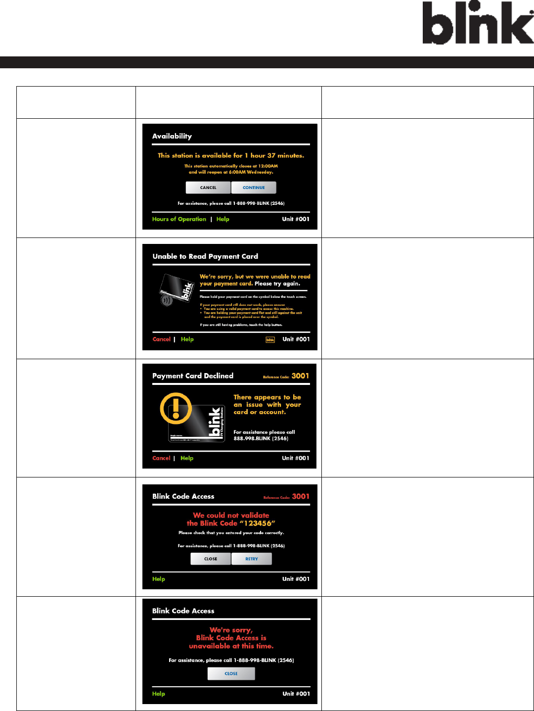
SITUATION
Screen Displayed ACTION
The Station will be
closed less than N
minutes. (Default: 120
minutes.)
1. In this case, the Station will be close
within 1 hour 37 minutes.
2. You could either touch “Continue” to
charge now and expect to stop within
1 hour 37 minutes, or touch “Cancel”
to wait until the Station reopen at
6:00AM Wednesday.
3. For more assistance, please call
1-888-998-BLINK (2546).
Unable to Read Pay-
ment Card
1. Please try to swipe card again or
touch “Help” for more information.
Payment Card De-
clined
1. There appears to be an issue with
your card or account.
2. For assistance, please call
1-888-998-BLINK (2546).
Blink Code is not
Valid.
1. This code has expired. Blink Codes
are only valid for 24 hours.
2. To purchase another Blink Code visit
www.blinkcode.com.
3. For assistance, please call
1-888-998-BLINK (2546).
Blink Code Access is
unavailable.
1. Blink Code is unavailable at this
time.
2. For assistance, please call
1-888-998-BLINK (2546).
47
Charge on.
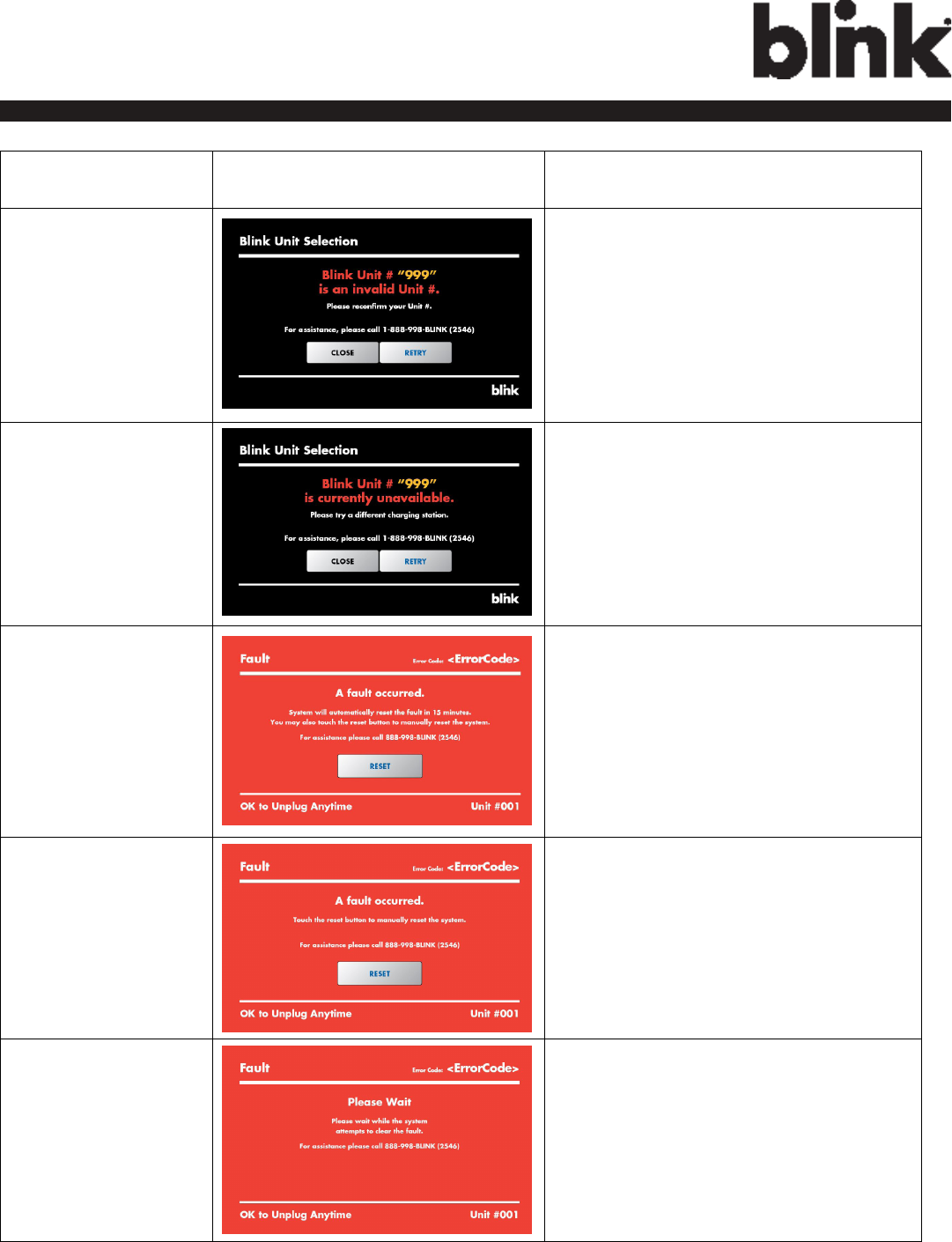
SITUATION
Screen Displayed ACTION
The Selected Blink Unit
is an invalid Unit.
1. Please reconrm your Unit # and retry.
2. For assistance, please call
1-888-998-BLINK (2546).
The Selected Blink Unit
is currently in-use or
unavailable.
1. Please try to a different chargeing
station.
2. For assistance, please call
1-888-998-BLINK (2546).
Fault (Case 1).
1. A fault occurred.
2. System will automatically reset the
fault in 15 minutes.
3. You may also touch the reset button
to manually reset the system.
4. For assistance, please call
1-888-998-BLINK (2546).
Fault (Case 2).
1. A fault occurred.
2. Touch the reset button to manually
reset the system.
3. For assistance, please call
1-888-998-BLINK (2546).
Fault (Case 3).
1. A fault occurred.
2. Please wait while the system attemps
to clear the fault.
3. For assistance, please call
1-888-998-BLINK (2546).

48
Charge on.
5.5 General Care
The exterior of the Charger is designed to be waterproof and dust proof. To ensure proper maintenance of the
charger, follow these guidelines:
• Despite the water resistance of the enclosure, when cleaning it is preferred to not direct streams of water at
the unit. Clean with a soft, damp cloth.
• Make sure the charging plug is put back in the holster after charging to avoid damage.
• Ensure the power cable is stored on the charger after use to avoid damage.
• If the power cable or the charging plug is damaged contact Customer Support.
5.6 Customer Support
If the Charger is not operational or you need our assistance, please call:
1-888-998-BLINK (2546).