LITE ON TECHNOLOGY KB27RF002 RF 27MHz KEYBOARD User Manual SK 7265 User Manual
Lite-on Technology Corp. RF 27MHz KEYBOARD SK 7265 User Manual
USER MANUAL

LITE-ON Technology Department: HIS R&D
User’s Manual
For Model : SK-7265
RF Wireless Keyboard
Prepared :Muchuan Lee
Version: 1.0
Department: HIS, R&D
Date: NOV. 11th, 2003

LITE-ON Technology Department: HIS R&D
Table of Contents
1. GENERAL
MAIN FEATURE:............................................................................................................1
SOFTWARE REQUIREMENT.............................................................................................1
2. MECHANICAL ID..........................................................................................................................
KEYBOARD/RECEIVER ......................................................................................................4
3. ELECTRICAL FEATURE
3.1 KEYBOARD TRANSMITTER ......................................................................................................3
3.1.1 Operating voltage ....................................................................................................................................................3
3.1.2 Current consumption................................................................................................................................................3
3.1.3 Power consumption..................................................................................................................................................3
3.1.4 Low Power Indicator................................................................................................................................................3
3.1. PCB Assembly ....................................................................................................................................................
3.1.6 Effective Transmission Distance..............................................................................................................................4
3.2 RECEIVER.......................................................................................................................4
3.2.1 Operating voltage ....................................................................................................................................................4
3.2.2 Current consumption................................................................................................................................................4
3.2.3 Power consumption....................................................................................................................................................
3.2.4 Pin outs of PS2 min-DIN connector...........................................................................................................................
3.2.6 Circuitry...................................................................................................................................................................4
3.2.7.1 PCB Assembly.............................................................................................................................................5
3.2.7.2 Cable ...........................................................................................................................................................5
3.3 FUNCTION DESCRIPTION................................................................................................5
3.3.1 Interface specification with host PC ........................................................................................................................5
3.3.2. Channel and ID default setting................................................................................................................................5
3.3.3 Channel and ID numbers .........................................................................................................................................5

SK-7265 RF WIRELESS KEYBOARD Page No: 1 of
27
1. General
SK-7265 is a set of 27 MHZ RF keyboard product, the product is composed of a set
of wireless desk top keyboard and USB receiver. The keyboard includes standard
function keys and several easy access keys.
General the receiver supports both keyboard and mouse function. Hereunder are only
described keyboard functionality in the product specification ,not excluded mouse
portion.The mouse is a optional device and the functionality will be described in the
specification of mouse.
Product package includes wireless keyboard and receiver, mouse device is optional
according to customer’s demend.
1.1 Main feature
The product provides 4 channels /256 ID operation to prevent frequency
interference.there are two channel for keyboard and another two channel for mouse.
The receiver interface of supporting both keyboard and mouse to the system
through USB ports.
.
High performance ,have a reliable and stable function in RF link.
Phantom key detection.
Low power consumption .
4k bps baud rate in air.
Provides 2 +2 RF channels .
256 ID codes randomly generated to resist interference.
EEPROM interface for ID keeping
Low battery detector function for transmitter.
1.2 Software requirement
The keyboard, receiver and drivers are compatible with operating systems that are
WIN98, Windows Millennium and Windows 2000. The driver-application also
must meet all current and future Microsoft WHQL requirements.

SK-7265 RF WIRELESS KEYBOARD Page No: 2 of
27
2. Mechanical ID
Keyboard:
SK-7265 RF WIRELESS KEYBOARD Page No: 3 of
27
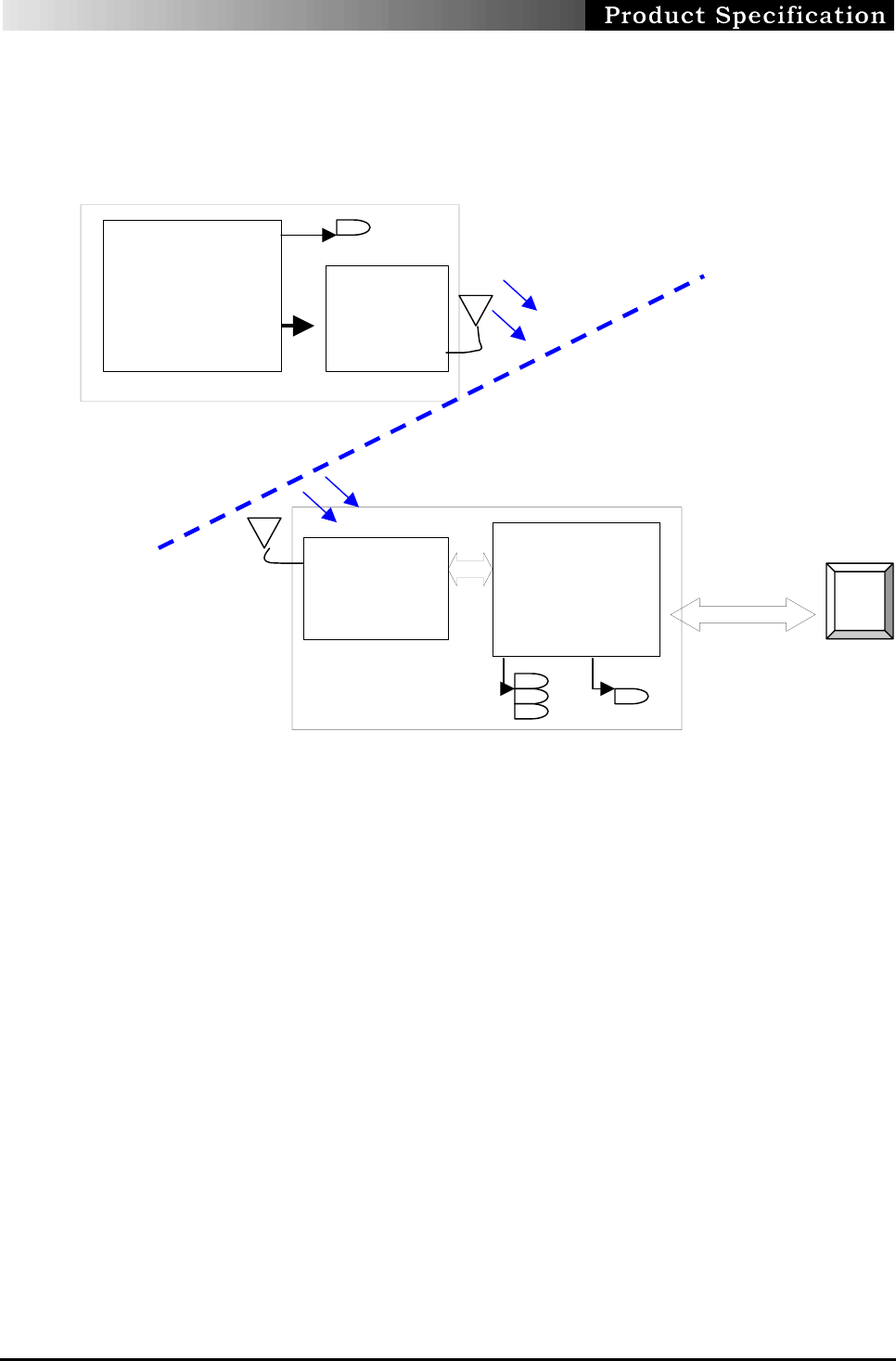
3. Electrical Specification
Functional Block diagram:
Microprocessor EMC78P451
3.1 Keyboard Transmitter
Operating voltage
The operating voltage range for keyboard is 2.2 ~ 3.3 Vdc.
There are 2 AA batteries providing 3.0V for operation
Current consumption
Typical current consumption is 8 mA, .Maximum at 10 mA
Suspend current is under 50 uA.
Power consumption
The power consumption is less than 0.024 W at operation mode and 150 uW
at sleep mode.
Low Power Indicator
Low power indicator on the keyboard will be lit during hitting key when the
battery voltage applying to keyboard is less than about 2.5V.
CPU
Crystal : 4.9152MH RF Link
PC Host
PS2 Interface
cable
Low power indicator
N
um
L
,CAP, Scrol LED Data indicator
Keyboard
(Base-Band)
CPU: EMC78P257
&CYC63743
Crystal : 8MHZ
USB clock :6MHZ internal
TX-Freq :
27.095MHz
27.145 MHz
RX-Freq :
Crystal : 26.690
/
2
6.
6
4
0
MHz
Base-Band
Microprocessor
MA6135

SK-7265 RF WIRELESS KEYBOARD Page No: 4 of
27
Effective Transmission Distance
Effective transmission distance is 2 meters.
3.1.4 Features of keyboard
This model contains easy access keys, including web. and multimedia keys .
There is one LED on the keyboard for battery low power indication.
.It has a standard keyboard function with the language layout of US English
version.
Two AA batteries are to be installed at the bottom of the keyboard for operation.
There is a channel selection button at the bottom side of keyboard .
Low battery power consumption and high RF performance design.
Easy Acess Key Code Table
Win2000 compatible, they are include,refer to table below: USB Hot key
No
. Usage Name / Key
Name
1 Scan Next Track
2 Scan Previous Track
3 Stop
4 Play / Pause
5 Mute
6 Volume Increment
7 Volume Decrement
8 EMail Reader
9 WWW Home
10 WWW Back
11 WWW Forward
12 WWW Favorites
13 WWW Search
14 WWW Refresh
*These controls are currently supported in Windows Me only.
3.2 Receiver
3.2.1 Operating voltage
Voltage supplied to keyboard receiver : 5+/-0.25 VDC
With ripple lower than 150mv, and capable of supply load current up to 100
mA with voltage drop less than 0.25 VDC
Current consumption
Under nominal 5 VDC power supplied, typical current

SK-7265 RF WIRELESS KEYBOARD Page No: 5 of
27
operating is 40 mA and 45 mA at maximum.
Cable connector :
4
pin USB connector compatible with USB V1.1 spec..
LED indicators
There are four indicators on the receiver included
NumLock ,CapLock,ScroLock and Receiving Data LEDs. The data indicator
will be ON only when data is receiving from the transmitter.
3.3 Function description
3.3.1 Interface specification with host PC
The keyboard Receiver uses USB interface to PC host in data
communication between them.
3.3.2 Operation
Battery Installation
Installs two AA batteries to transmitter and connected the receiver with PC
system, it’s ready for connection procedure.
Connection (ID & channel Pairing) procedure
Procedure by steps
Step-1: Pressing the channel button one time of receiver first ,the DATA LED will
be lit up.
Step-2: Within 10 seconds after RX button pressed , press the channel button of
TX. The DATA LED will turn OFF when it completed connection between TX and RX.
Step-3: Go to the normal operate.
Note: Preset default channel setting in the production line before packing
for delivery
Channel and ID numbers
Channel: two channels including CH1,27.095 and CH2 ,27.145 for
keyboard .
ID: There has a randomly 256 ID from for selection.

SK-7265 RF WIRELESS KEYBOARD Page No: 6 of
27
Note: The ID indication is to prevent from interfering each other.
End of SK-7265 User’s Manual
FEDERAL COMMUNICATIONS COMMISSION
This device complies with Part 15 of the FCC Rules. Operation is subject to the
following two conditions:(1) this device may not cause harmful interference, and (2)
this device must accept any interference received, including interference that may
cause undesired operation.
Changes or modifications not expressly approved by the party responsible for
compliance could void the user‘s authority to operate the equipment.
NOTE
This equipment has been tested and found to comply with the limits for a Class B
digital device, pursuant to Part 15 of the FCC Rules. These limits are designed to
provide reasonable protection against harmful interference in a residential installation.
This equipment generates, uses and can radiated radio frequency energy and, if not
installed and used in accordance with the instructions, may cause harmful interference
to radio communications. However, there is no guarantee that interference will not
occur in a particular installation If this equipment does cause harmful interference to
radio or television reception, which can be determined by turning the equipment off
and on, the user is encouraged to try to correct the interference by one or more of the
following measures:
-Reorient or relocate the receiving antenna.
-Increase the separation between the equipment and receiver.
-Connect the equipment into an outlet on a circuit different from that to which the
receiver is connected.
-Consult the dealer or an experienced radio/TV technician for help.
Note:
This device and its antenna(s) used for this transmitter must not be co-located or
operating in conjunction with any other antenna or transmitter.