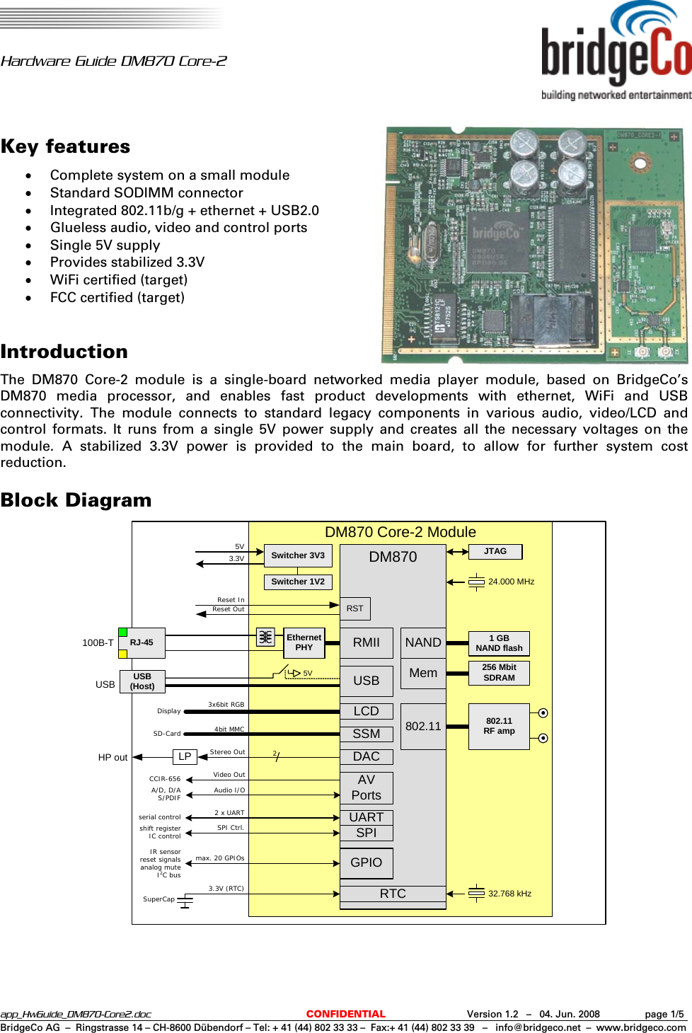
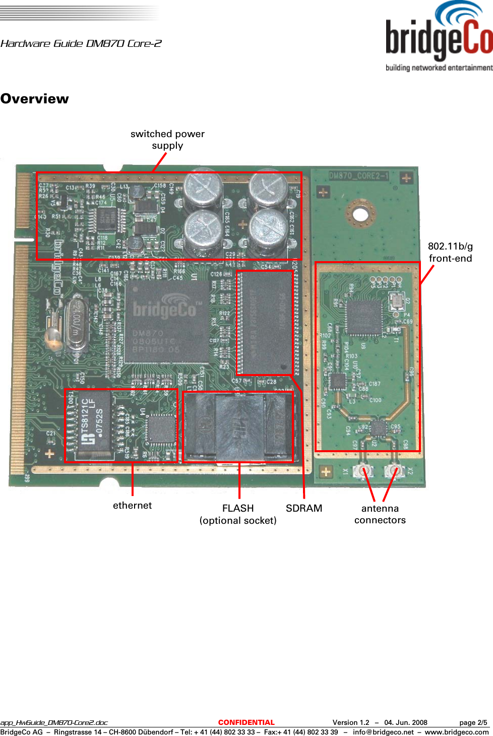
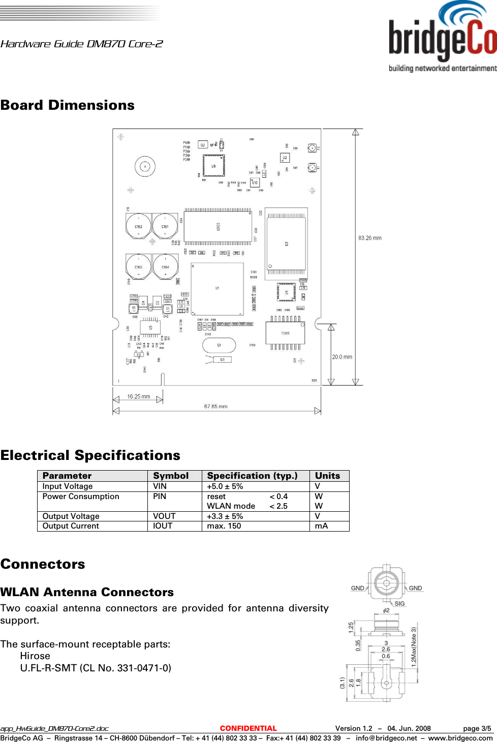
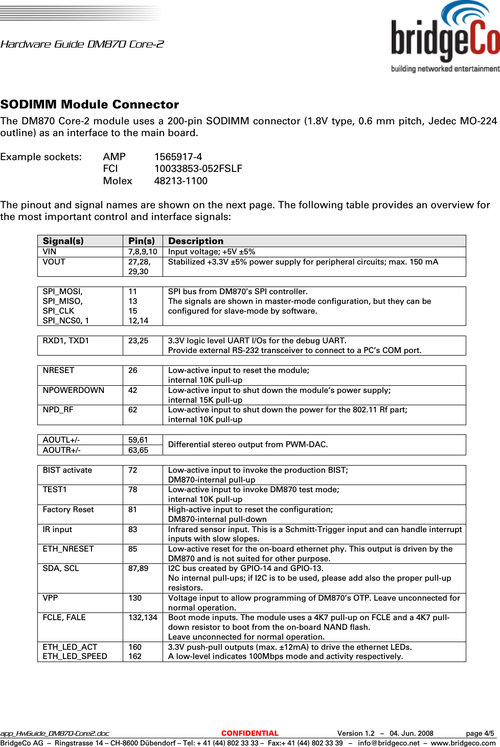
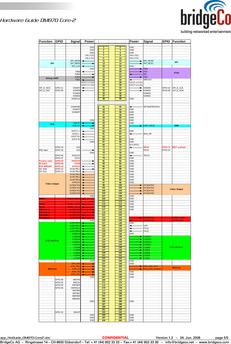
LITE ON TECHNOLOGY NM100BB DIGITAL MEDIA PLAYER MODULE User Manual app HwGuide DM870 Core2

LITE-ON Technology Corp. DIGITAL MEDIA PLAYER MODULE app HwGuide DM870 Core2

Users Manual

  Hardware Guide DM870 Core-2  app_HwGuide_DM870-Core2.doc  CONFIDENTIAL  Version 1.2   –   04. Jun. 2008  page 1/5BridgeCo AG  –  Ringstrasse 14 – CH-8600 Dübendorf – Tel: + 41 (44) 802 33 33 –  Fax:+ 41 (44) 802 33 39   –   info@bridgeco.net  –  www.bridgeco.com Key features • Complete system on a small module • Standard SODIMM connector • Integrated 802.11b/g + ethernet + USB2.0 • Glueless audio, video and control ports • Single 5V supply • Provides stabilized 3.3V • WiFi certified (target) • FCC certified (target)  Introduction The DM870 Core-2 module is a single-board networked media player module, based on BridgeCo’s DM870 media processor, and enables fast product developments with ethernet, WiFi and USB connectivity. The module connects to standard legacy components in various audio, video/LCD and control formats. It runs from a single 5V power supply and creates all the necessary voltages on the module. A stabilized 3.3V power is provided to the main board, to allow for further system cost reduction. Block Diagram Ethernet PHYDM870 256 MbitSDRAMJTAGRJ-45100B-TMemUSBGPIO24.000 MHzReset InNAND 1 GBNAND flash802.11RF amp802.11RMIISPIRTC 32.768 kHzUSB(Host)USBRSTUART5VSwitcher 3V3Switcher 1V25VDM870 Core-2 ModuleReset Out3.3VStereo OutVideo OutAudio I/O4bit MMC3x6bit RGB2 x UARTSPI Ctrl.max. 20 GPIOs3.3V (RTC)SuperCapIR sensorreset signalsanalog muteI2C busshift registerIC controlserial controlA/D, D/AS/PDIFCCIR-656LP 2HP outDisplaySD-CardAV PortsLCDSSMDAC
  Hardware Guide DM870 Core-2  app_HwGuide_DM870-Core2.doc  CONFIDENTIAL  Version 1.2   –   04. Jun. 2008  page 2/5BridgeCo AG  –  Ringstrasse 14 – CH-8600 Dübendorf – Tel: + 41 (44) 802 33 33 –  Fax:+ 41 (44) 802 33 39   –   info@bridgeco.net  –  www.bridgeco.com Overview                                      switched power supply 802.11b/gfront-end antenna connectors SDRAM FLASH(optional socket)ethernet
  Hardware Guide DM870 Core-2  app_HwGuide_DM870-Core2.doc  CONFIDENTIAL  Version 1.2   –   04. Jun. 2008  page 3/5BridgeCo AG  –  Ringstrasse 14 – CH-8600 Dübendorf – Tel: + 41 (44) 802 33 33 –  Fax:+ 41 (44) 802 33 39   –   info@bridgeco.net  –  www.bridgeco.com Board Dimensions   Electrical Specifications Parameter  Symbol  Specification (typ.)  Units Input Voltage  VIN  +5.0 ± 5%  V Power Consumption  PIN  reset  < 0.4 WLAN mode  < 2.5 W W Output Voltage  VOUT  +3.3 ± 5%  V Output Current  IOUT  max. 150  mA  Connectors WLAN Antenna Connectors Two coaxial antenna connectors are provided for antenna diversity support.  The surface-mount receptable parts:  Hirose   U.FL-R-SMT (CL No. 331-0471-0)
  Hardware Guide DM870 Core-2  app_HwGuide_DM870-Core2.doc  CONFIDENTIAL  Version 1.2   –   04. Jun. 2008  page 4/5BridgeCo AG  –  Ringstrasse 14 – CH-8600 Dübendorf – Tel: + 41 (44) 802 33 33 –  Fax:+ 41 (44) 802 33 39   –   info@bridgeco.net  –  www.bridgeco.com SODIMM Module Connector The DM870 Core-2 module uses a 200-pin SODIMM connector (1.8V type, 0.6 mm pitch, Jedec MO-224 outline) as an interface to the main board.  Example sockets:  AMP  1565917-4  FCI 10033853-052FSLF  Molex 48213-1100  The pinout and signal names are shown on the next page. The following table provides an overview for the most important control and interface signals:  Signal(s)  Pin(s)  Description VIN  7,8,9,10  Input voltage; +5V ±5% VOUT 27,28, 29,30 Stabilized +3.3V ±5% power supply for peripheral circuits; max. 150 mA    SPI_MOSI, SPI_MISO, SPI_CLK SPI_NCS0, 1 11 13 15 12,14 SPI bus from DM870’s SPI controller. The signals are shown in master-mode configuration, but they can be configured for slave-mode by software.    RXD1, TXD1  23,25  3.3V logic level UART I/Os for the debug UART. Provide external RS-232 transceiver to connect to a PC’s COM port.    NRESET  26  Low-active input to reset the module; internal 10K pull-up NPOWERDOWN  42  Low-active input to shut down the module’s power supply; internal 15K pull-up NPD_RF  62  Low-active input to shut down the power for the 802.11 Rf part; internal 10K pull-up    AOUTL+/- 59,61 AOUTR+/- 63,65 Differential stereo output from PWM-DAC.    BIST activate  72  Low-active input to invoke the production BIST; DM870-internal pull-up TEST1  78  Low-active input to invoke DM870 test mode; internal 10K pull-up Factory Reset  81  High-active input to reset the configuration; DM870-internal pull-down IR input  83  Infrared sensor input. This is a Schmitt-Trigger input and can handle interrupt inputs with slow slopes. ETH_NRESET  85  Low-active reset for the on-board ethernet phy. This output is driven by the DM870 and is not suited for other purpose. SDA, SCL  87,89  I2C bus created by GPIO-14 and GPIO-13. No internal pull-ups; if I2C is to be used, please add also the proper pull-up resistors. VPP  130  Voltage input to allow programming of DM870’s OTP. Leave unconnected for normal operation. FCLE, FALE  132,134  Boot mode inputs. The module uses a 4K7 pull-up on FCLE and a 4K7 pull-down resistor to boot from the on-board NAND flash. Leave unconnected for normal operation. ETH_LED_ACT ETH_LED_SPEED 160 162 3.3V push-pull outputs (max. ±12mA) to drive the ethernet LEDs. A low-level indicates 100Mbps mode and activity respectively.
  Hardware Guide DM870 Core-2  app_HwGuide_DM870-Core2.doc  CONFIDENTIAL  Version 1.2   –   04. Jun. 2008  page 5/5BridgeCo AG  –  Ringstrasse 14 – CH-8600 Dübendorf – Tel: + 41 (44) 802 33 33 –  Fax:+ 41 (44) 802 33 39   –   info@bridgeco.net  –  www.bridgeco.com Function GPIO Signal Power Power Signal GPIO FunctionGND 12GNDGND 34GNDGND 56GNDVIN (+5V) 78VIN (+5V)VIN (+5V) 910VIN (+5V)SPI_MOSI 11 12 SPI_NCS0SPI_MISO 13 14 SPI_NCS1SPI_CLK 15 16 GNDGND 17 18 TMSTXD0 19 20 TCKRXD0 21 22 TDIRXD1 23 24 TDOTXD1 25 26 NRESETVOUT (+3.3V) 27 28 VOUT (+3.3V)VOUT (+3.3V) 29 30 VOUT (+3.3V)SPI_E_NCS GPIO-11 SSMD7 31 32 SSMD6 GPIO-10 SPI_E_CLKSPI_E_SDI GPIO-09 SSMD5 33 34 SSMD4 GPIO-08 SPI_E_SDOSSMD3 35 36 SSMD2SSMD0 37 38 SSMD1SSMCLK 39 40 GNDSSMCMD 41 42 NPOWERDOWNSSMCP 43 44 GNDSSMWP 45 46 GND47 48 GND49 50 GNDGND 51 52 GNDUSB D- 53 54 GNDUSB D+ 55 56 USB_VBUSGND 57 58AOUT L+ 59 60 GNDAOUT L- 61 62 NPD_RFAOUT R+ 63 64AOUT R- 65 66 GNDGND 67 68 GND69 70 3V3 (RTC)GPIO-16 A23 71 72 NCS3 GPIO-17 BIST activateIRQ input GPIO-18 A22 73 74 NCS2 GPIO-19GND 75 76 GNDGPIO-06 PDOUT1 77 78 TEST1GPIO-07 VCO1 79 80 GNDFactory reset GPIO-04 PDOUT0 81 82 GNDIR input GPIO-05 VCO0 83 84 GNDETH NRESET GPIO-12 AV3CLK 85 86 GNDI2C SDA GPIO-14 AV3CTRL1 87 88 GNDI2C SCL GPIO-13 AV3CTRL0 89 90 GNDAV0CTRL2 91 92 GNDAV0CTRL1 93 94 GNDAV0CTRL0 95 96 GNDAV0CLK 97 98 GNDAV0DATA3 99 100 AV1DATA3AV0DATA2 101 102 AV1DATA2AV0DATA1 103 104 AV1DATA1AV0DATA0 105 106 AV1DATA0GND 107 108 GND256FS ADDA_MCLK 109 110 GNDGND 111 112 GNDLRCK ADDA_LRCK 113 114 GNDSCLK ADDA_SCLK 115 116 GNDA/D data 1 AV2DATA3 117 118 GNDA/D data 0 AV2DATA2 119 120D/A data 1 AV2DATA1 121 122D/A data 0 AV2DATA0 123 124 AV4DATA1 SPDIF outputGND 125 126 AV4DATA0 SPDIF inputLCDCTRL3 127 128 GNDLCDCTRL2 129 130 VPPLCDCTRL1 131 132 FCLELCDCTRL0 133 134 FALELCDCLK 135 136 GNDLCDD16 137 138 LCDD17LCDD14 139 140 LCDD15LCDD12 141 142 LCDD13LCDD10 143 144 LCDD11LCDD8 145 146 LCDD9LCDD6 147 148 LCDD7LCDD4 149 150 LCDD5LCDD2 151 152 LCDD3LCDD0 153 154 LCDD1GND 155 156 GNDETH_RX- 157 158 GNDETH_RX+ 159 160 ETH_LED_ACTETH_CT 161 162 ETH_LED_SPEEDETH_TX- 163 164 GNDETH_TX+ 165 166 GNDGND 167 168 GNDGPIO-00 MIICRS 169 170GPIO-01 MIICOL 171 172GPIO-02 MIITXER 173 174GPIO-03 MIITXCLK 175 176MIITXD0 177 178MIITXD1 179 180MIIRXD0 181 182MIIRXD1 183 184GND 185 186 GND187 188189 190191 192GPIO-15 NWAIT 193 194GND 195 196 GNDGND 197 198 GNDGND 199 200 GNDLCD InterfaceDebug UARTSPI SPIEthernet EthernetUSB USBJTAGVideo OutputVideo OutputLCD Interface
FEDERAL COMMUNICATIONS COMMISSION INTERFERENCE STATEMENT This equipment has been tested and found to comply with the limits for a Class B digital device, pursuant to Part 15 of the FCC Rules. These limits are designed to provide reasonable protection against harmful interference in a residential installation. This equipment generates, uses and can radiate radio frequency energy and, if not installed and used in accordance with the instructions, may cause harmful interference to radio communications. However, there is no guarantee that interference will not occur in a particular installation. If this equipment does cause harmful interference to radio or television reception, which can be determined by turning the equipment off and on, the user is encouraged to try to correct the interference by one or more of the following measures: –  Reorient or relocate the receiving antenna. –  Increase the separation between the equipment and receiver. –  Connect the equipment into an outlet on a circuit different from that to which the receiver is connected. –  Consult the dealer or an experienced radio/TV technician for help. CAUTION: Any changes or modifications not expressly approved by the party responsible for compliance could void the user's authority to operate the equipment.  RF exposure warning  ·    This equipment must be installed and operated in accordance with provided instructions and the antenna(s) used for this transmitter must be installed to provide a separation distance of at least 20 cm from all persons and must not be co-located or operating in conjunction with any other antenna or transmitter. End-users and installers must be provide with antenna installation instructions and transmitter operating conditions for satisfying RF exposure compliance.    This device complies with Part 15 of the FCC Rules. Operation is subject to the following two conditions: (1) this device may not cause harmful interference, and (2) this device must accept any interference received, including interference that may cause undesired operation.  Canada Warning "Industry Canada regulatory information Operation is subject to the following two conditions: (1) this device may not cause interference, and (2) this device must accept any interference, including interference that may cause undesired operation of the device. ""The user is cautioned that this device should be used only as specified within this manual to meet RF exposure requirements. Use of this device in a manner inconsistent with this manual could lead to excessive RF exposure conditions."

Navigation menu