LITE ON TECHNOLOGY PLAYFIR1 Play-Fi Receiver User Manual Phorus
LITE-ON Technology Corp. Play-Fi Receiver Phorus
(Play-Fi Receiver) UserMan
Confidential - Do Not Distribute Revision A - Sep. 9 2011 page 1 of 18
Deckard
Product Requirement Document
PHORUS-DKR-PRD-0001
September 9, 2011
Revision A
Confidential - Do Not Distribute Revision A - Sep. 9 2011 page 2 of 18
Document Change Summary
Date:
Revision:
Changes:
Author:
2011.09.09
A
Initial Release
D. O'Brien / D. Lau

Confidential - Do Not Distribute Revision A - Sep. 9 2011 page 3 of 18
Table of Contents
Table of Contents .......................................................................................................................................... 3
1 Document Scope ........................................................................................................................................ 4
1.1 Definition of Terms .............................................................................................................................. 4
1.2 Notation ............................................................................................................................................... 4
1.3 Highlight Color Codes.......................................................................................................................... 4
2 Applicable Documents ............................................................................................................................... 5
2.1 Reference Design Documents ............................................................................................................ 5
2.2 Order of Precedence ........................................................................................................................... 5
3 Product Overview ....................................................................................................................................... 6
3.1 Features List ........................................................................................................................................ 6
3.2 What is in the Box ................................................................................................................................ 6
4 User Interface (UI) ...................................................................................................................................... 7
4.1 Input Methods ...................................................................................................................................... 7
5 Localization ................................................................................................................................................ 8
5.1 Product SKUs ...................................................................................................................................... 8
5.2 Languages ........................................................................................................................................... 8
6 Hardware .................................................................................................................................................... 9
6.1 Mechanical Arrangement / Industrial Design ...................................................................................... 9
6.2 Rear Panel ......................................................................................................................................... 10
6.3 Front Panel ........................................................................................................................................ 11
6.4 Printed Material ................................................................................................................................. 12
6.5 Serviceability ..................................................................................................................................... 12
6.6 Recyclability ....................................................................................................................................... 13
7 Features ................................................................................................................................................... 14
7.1 System Features ............................................................................................................................... 14
8 State Summary ........................................................................................................................................ 16
8.1 Power On/Off ..................................................................................................................................... 16
8.2 Power Transitions .............................................................................................................................. 16
8.3 Volume States ................................................................................................................................... 16
8.4 Mute State ......................................................................................................................................... 16
9 Technical Requirements .......................................................................................................................... 17
9.1 Power................................................................................................................................................. 17
9.2 DSP ................................................................................................................................................... 17
9.3 Testability .......................................................................................................................................... 18
10 Environmental and Reliability Requirements ......................................................................................... 18
11 Certification and Agency Compliance .................................................................................................... 18
11.1 Intellectual Property Certifications ................................................................................................... 18
11.2 Royalties .......................................................................................................................................... 18
11.3 Certifications .................................................................................................................................... 18
Confidential - Do Not Distribute Revision A - Sep. 9 2011 page 4 of 18
1 Document Scope
This document describes in engineering development terms the definition of Deckard. This document will
define the engineering platform with enough detail to meet the initial product concept while not
constraining the execution team on specific intricate design details.
This document is also a description of the functional behavior with sufficient detail in order to achieve an
accurate quotation, begin writing user guides and to begin developing test methods.
1.1 Definition of Terms
Shall – Term indicates a required element, e.g., "the unit shall play MP3 files".
Should – Term indicates a suggestion or preference, e.g., "the unit should attempt to read ID3V1 tags".
May – Term indicates an allowance, e.g., "the unit may play FLAC files".
Will – Term indicates a statement of fact. This is typically information used for clarity, such as "the unit
will be sold in France".
1.2 Notation
Requirements are divided into sub-sections based on system division and implementation conventions.
Each requirement is labeled as [Rx], where ‘R’ represents the ‘Requirement’ and ‘x’ marks the serial
number of each requirement.
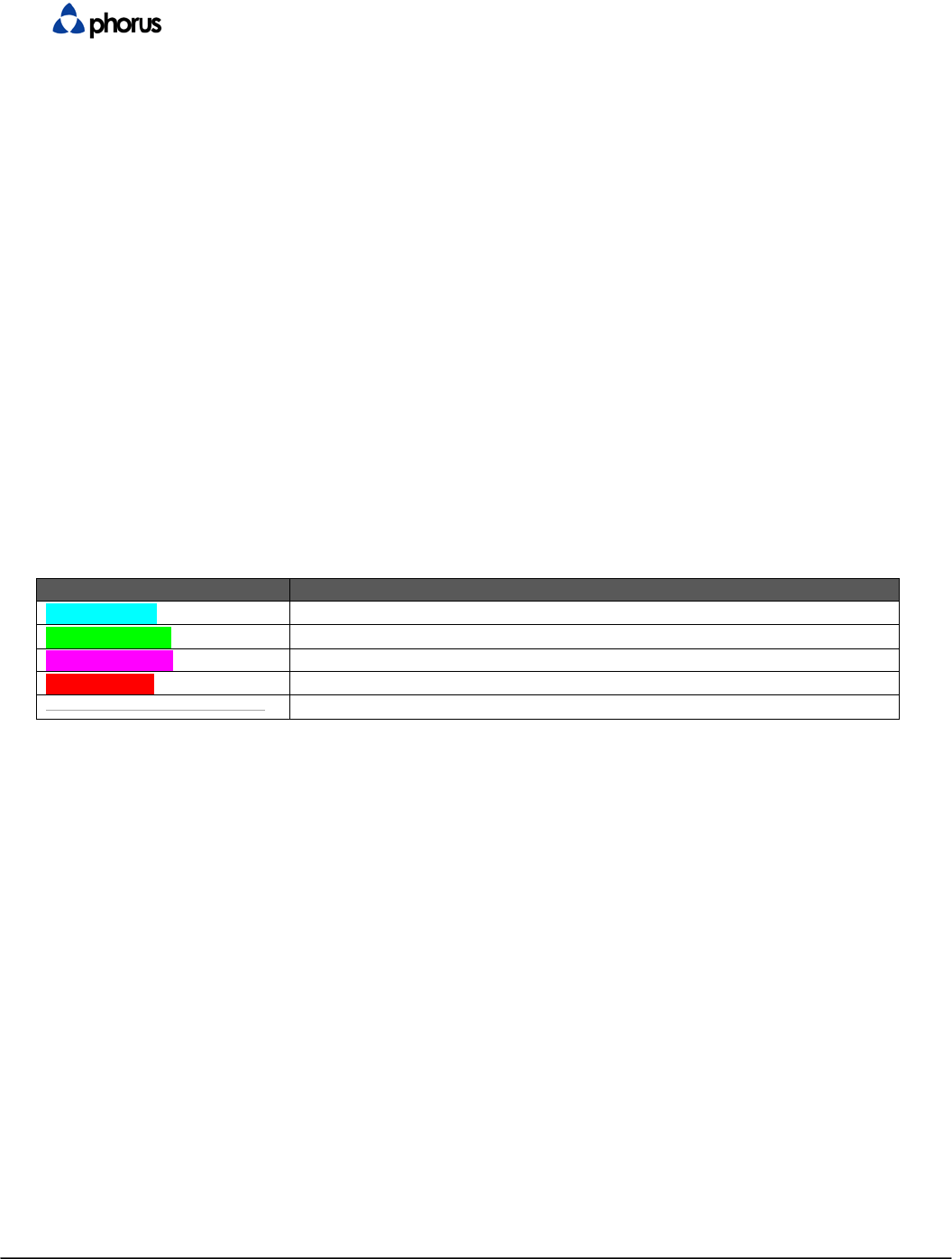
1.3 Highlight Color Codes
Color:
Meaning:
Blue Highlight
Indication of changes since the last revision
Green Highlight
Known open issues needing further clarification
Purple Highlight
Questions or notes for reviewers
Red Highlight
Incomplete sections
Gray text with strikethrough
Deleted sections
Confidential - Do Not Distribute Revision A - Sep. 9 2011 page 5 of 18
2 Applicable Documents
2.1 Reference Design Documents
The following documents form a part of this specification. Each utilized and referenced document shall be
the most recent released issue.
Phorus Reference Documentation
Reliability Test Specification
User Interface Specification
Mechanical Documents
Colors, Materials and Finishes (CMF)
Industrial Design Screen Print Specification
Reference Specifications
Bluetooth.org Qualification Program Reference Document V1.0
Bluetooth.org Advanced Audio Distribution Profile Specification V1.2
Bluetooth.org White Paper on Usage of Multiple Headphones V1.0RC5
2.2 Order of Precedence
In the event of a conflict between this specification and the references cited herein, the order of
precedence shall be this specification, then any Phorus reference documents, and finally any appendices.
Confidential - Do Not Distribute Revision A - Sep. 9 2011 page 6 of 18
3 Product Overview
3.1 Features List
[R1]. Bluetooth Advanced Audio Distribution Profile (A2DP) sink for wireless stereo audio streaming
[R2]. Use of SBC audio codec for A2DP
[R3]. Support pairing with a minimum of 8 devices
[R4]. On board power and volume +/- buttons
[R5]. Factor defaults reset button
[R6]. System/Power status LED (bi-color: White, Amber)
[R7]. Bluetooth status LED (single color: Blue)
[R8]. Wi-Fi status LED (single color: White)
[R9]. Audio Out (3.5mm Stereo Mini)
[R10]. World Wide Switching power supply technology (First SKU: USA)
[R11]. Low standby power (<0.5W) EuP Requirement 2013
[R12]. USB charging of external devices while in AC operating mode
[R13]. Firmware update via USB
3.1.1 Product Description
Deckard is a wireless Hi-Fi stereo accessory that receives audio over Bluetooth and Wi-Fi and streams it
to powered speakers or line-level inputs.
3.2 What is in the Box
[R14]. The following are accessories included with the product.
Item:
Requirement:
Deckard
Mandatory
AC Power Supply
Mandatory
Interchangeable Plugs Highly Desirable for EMEA
(First SKU: Fixed pin for USA)
12” USB A to USB micro
Cable
Mandatory
4" 3.5mm to Female RCA
cable
Mandatory
Quick Start Guide
Mandatory
Warranty Card Mandatory
Confidential - Do Not Distribute Revision A - Sep. 9 2011 page 7 of 18
4 User Interface (UI)
4.1 Input Methods
4.1.1 Buttons
[R15]. Power: ON/OFF
[R16]. Volume Down
[R17]. Volume Up
[R18]. Reset
[R19]. Bluetooth Control
[R20]. Audio Out Control

Confidential - Do Not Distribute Revision A - Sep. 9 2011 page 8 of 18
4.1.2 User Input Feedback Methods
[R21]. LEDs (The functionality of the LEDs can be found here)
[R22]. Audible Sounds for connect and disconnect (played through the Audio Out)
5 Localization
[R23]. This product shall be engineered such that localization involves the fewest possible variables.
5.1 Product SKUs
[R24]. The product shall have the following SKUs. These SKUs are differentiated by the power supply
plugs. (see Power Section).
[R25]. Americas (Suffix: AM) – Fixed US Plug
[R26]. EMEA (Suffix: EU) – two replaceable plugs: UK and EU (Highly desirable)
5.2 Languages
[R27]. The following languages are required for the AM beauty carton:
a. English
b. French (Français)
c. Spanish (Español)
[R28]. The following languages are required for the EU beauty carton:
a. English
b. French (Français)
c. Spanish (Español)
d. German (Deutsch)
e. Dutch (Nederlands)
f. Italian (Italiano)
[R29]. The following languages are required for the AM quick start guide:
a. English
b. French (Français)
c. Spanish (Español)
[R30]. The following languages are required for the EU quick start guide:
a. English
b. French (Français)
c. Spanish (Español)
d. German (Deutsch)
e. Dutch (Nederlands)
f. Italian (Italiano)
Confidential - Do Not Distribute Revision A - Sep. 9 2011 page 9 of 18
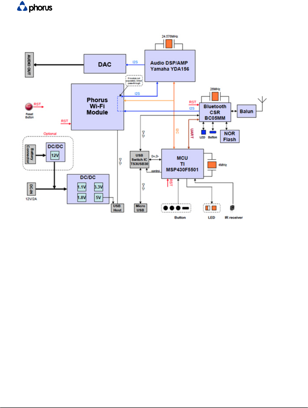
6 Hardware
Figure 1: Main System Block Diagram
NOTE: I2S may require routing topology to support all use cases:
1. BT to Phorus Wireless Module
2. Phorus Wireless Module to DSP
3. BT to DSP, if Phorus Wireless Module is not populated
4. DSP to Phorus Wireless Module for streaming audio output
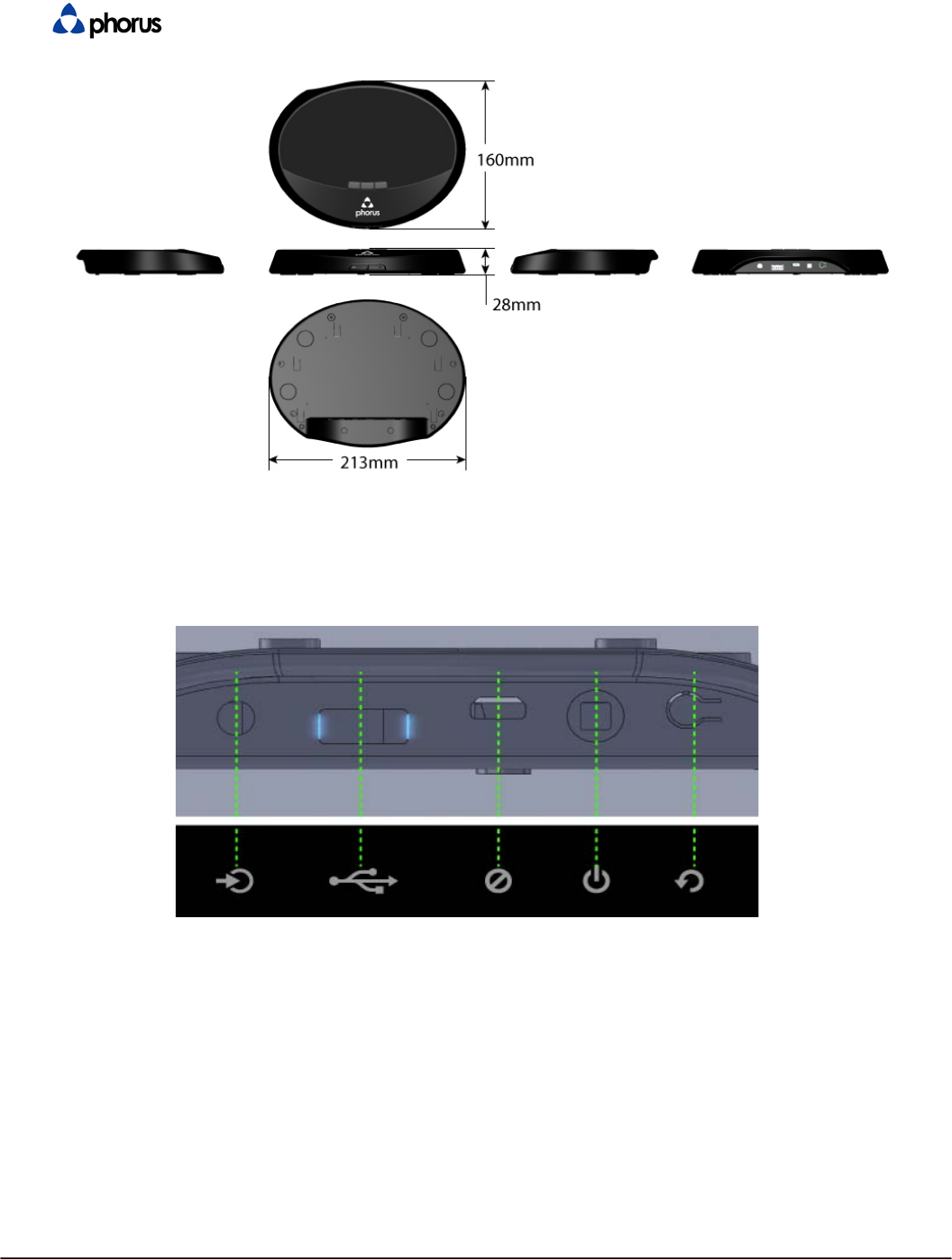
6.1 Mechanical Arrangement / Industrial Design
Confidential - Do Not Distribute Revision A - Sep. 9 2011 page 10 of 18
Figure 3: Industrial Design (not to be used for production)
[R31]. Dimensions indicated above.
[R32]. The system shall conform to the design language specified by the ID guidelines.
6.2 Rear Panel
Figure 4: 2D drawing of the back and bottom panel (not to be used for production)
Confidential - Do Not Distribute Revision A - Sep. 9 2011 page 11 of 18
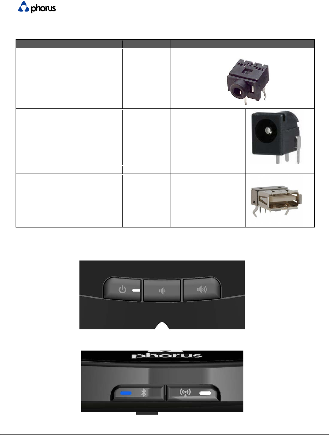
6.2.1 Connectors
The input and output sections of the rear panel are as follows:
Connector:
Number #:
Type (Images for informational use only):
[R33]. Mini Audio Jack (Audio Out)
3.5mm COLOR: LIME GREEN 1
[R34]. Power plug
1
3.5mm power connector
[R35]. USB
1
Micro USB
[R36]. USB
1
Type A
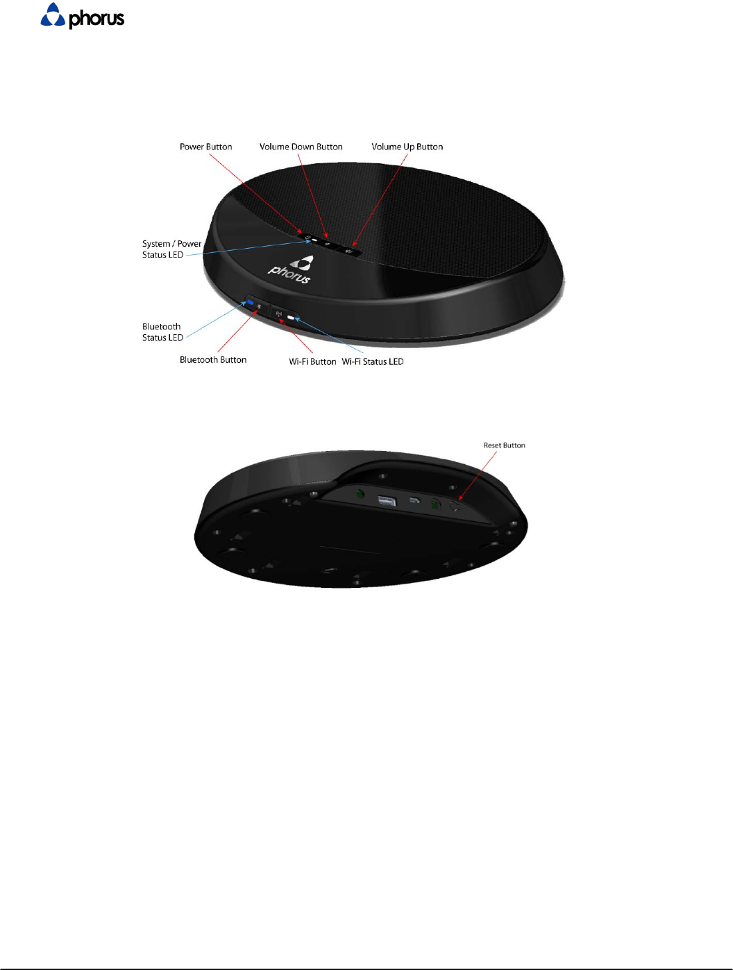
6.3 Front Panel
Figure 5: Top panel (not to be used for production)
Figure 6: Front panel (not to be used for production)

Confidential - Do Not Distribute Revision A - Sep. 9 2011 page 12 of 18
6.3.1 Buttons and Switches
The top panel shall have the following buttons:
[R37]. Power
[R38]. Volume Down
[R39]. Volume Up
The font panel shall have the following buttons:
[R40]. Bluetooth button for pairing
[R41]. Wi-Fi button for WPS
6.3.2 LEDs
[R42]. The top panel shall have one bi-color System/Power Status LED (White and Amber) sharing one
light pipe
[R43]. The front panel shall have one single color Bluetooth LED (Blue)
[R44]. The front panel shall have one single color Wi-Fi LED (White)
6.4 Printed Material
6.4.1 Quick Start Guide
[R45]. The quick start guide be four color.
[R46]. The AM quick start guide shall have approximately 3 pages per language.
[R47]. The EM quick start guide shall have approximately 6 pages per language.
6.4.2 Warranty Card
[R48]. The warranty card shall be black and white.
6.4.3 Beauty Box
[R49]. The box shall be four color (CMYK).
[R50]. The box shall have varnish / UV coating.
[R51]. The box shall use recycled/recaptured materials where possible.
[R52]. The box shall be 0.08 Pt. or better card stock, 250 lb. or better C Kraft.
[R53]. The box shall meet all Phorus validation and reliability requirements, e.g. pass drop tests,
environmental tests.
6.4.4 Overpack Box
[R54]. The box shall be two color (PMS color).
[R55]. The box shall use recycled/recaptured materials where possible.
[R56]. The box shall be 0.08 Pt. or better card stock, 250 lb. or better C Kraft.
[R57]. The box shall meet all Phorus validation and reliability requirements, e.g. pass drop tests,
environmental tests.
6.4.5 Master Carton
[R58]. The quantity requirement is 4 units per master carton.
[R59]. Versions are to be differentiated by different master carton labels.
[R60]. The master carton shall be labeled with the serial numbers of the contained Deckard products.
6.5 Serviceability
[R61]. This product shall be designed for serviceability. The device shall allow reasonable ease of
access to internal components for service and/or repair.


Confidential - Do Not Distribute Revision A - Sep. 9 2011 page 14 of 18
7 Features
7.1 System Features
7.1.1 Bluetooth Audio Subsystem
[R63]. The system shall wirelessly pair to a Bluetooth-enabled device.
[R64]. The system shall be up to date with the latest version of the Bluetooth protocol specification v2.1
and be compatible with the Enhanced Data Rate (EDR) specification (Data Rate: 3 Mbit/s).
[R65]. The operating range of the system shall meet or exceed the requirement of a Bluetooth Class 2
device (Maximum permitted power: 2.5mW – 4dBm, Range: 30 feet).
[R66]. The BT test protocol shall demonstrate better than 0.1% BER (as a note this should correspond
to a receiver with better than -85dBm sensitivity) over a free air range of at least 12 meters
[R67]. Less than 0.1% BER shall be verified at 432 test points.
The test area is described as 360 degree radial cone, -15degrees to +40 degrees in elevation, 12
meters from the unit under test.
Each test point is within this cone at both -15 degree declination and +40 degree elevation, at 10
degree radial intervals. This yields a total of 72 test points (36 radial points * 2 elevation angles).
At each test point, the Class 2 transmitting device shall be oriented orthogonally in all 3 axis, 180
degrees in each axis (yielding a total of 6 orientations).
Up to 3 commercially available Class 2 transmitting devices shall be used during this test.
[R68]. The system shall pair with a Bluetooth enabled device in order to wirelessly stream audio content
from a Bluetooth audio source device. Advanced Audio Distribution Profile (A2DP) version 1.2 allows
the use of the mandatory Sub Band Coding (SBC) codec for compressing audio for efficient
streaming.
[R69]. The Bluetooth subsystem shall be capable of pairing and saving pairing information with a
minimum of 8 source devices.
7.1.2 Wi-Fi Audio Subsystem
[R70]. The system shall be able to accept audio from the Wi-Fi subsystem
[R71]. The Wi-Fi Audio subsystem shall employ 802.11n
[R72]. The Wi-Fi Audio subsystem shall also include BT A2DP Sink capability with similar performance
to the standalone BT module
[R73]. The Wi-Fi Audio subsystem shall have a minimum 400MHz ARM9 or equivalent performance
[R74]. The Wi-Fi Audio subsystem shall have a minimum of 128MB of Flash memory and 64MB of
DRAM
[R75]. The Wi-Fi Audio subsystem shall run the Linux operating system
[R76]. The Wi-Fi Audio subsystem shall be able to accept a I2S input from the Bluetooth Subsystem
and/or the incorporated BT A2DP sink system of the BT/Wi-Fi module
7.1.3 Power
[R77]. The system shall have the following power modes:
a. Normal operational mode (front panel standby LED is white).
b. Standby (front panel power LED is off).
c. Off mode (front panel power LED is off).
[R78]. When the system is off, a power command shall transition the unit from standby to operational
mode.
[R79]. When the system is in operational mode, a power command shall transition the unit from
operational mode to off.

Confidential - Do Not Distribute Revision A - Sep. 9 2011 page 15 of 18
[R80]. The system shall support an auto-off mode which causes the system to transition to off after 10
minutes of inactivity (i.e. no user input or no audio). The off mode shall comply with EuP 2013 power
standards.
[R81]. The auto-off mode shall capable of being disabled.
[R82]. The auto-off mode disable control shall be accessible via the Deckard UI or over Wi-Fi.
7.1.4 LEDs
[R83]. The system shall have one LED located on the top panel of the system. If the system is powered
on the Power/System LED shall indicate system status.
[R84]. The state of the auto-off mode shall be communicated to the user through the Power/System
state LED as defined in the Bishop User Interface document.
[R85]. Color (Orange or White) shall communicate
[R86]. The Blue LED shall indicate Bluetooth status.
[R87]. The Bluetooth LED status shall be as defined in the Bishop User Interface document.
7.1.5 Audio Out
[R88]. There shall be an analog audio output (3.5mm stereo mini).
[R89]. Nominal Output Level: −10 dBV
[R90]. Nominal Output Level VRMS: 0.316 V
[R91]. Nominal Output Level VPK: 0.447 V
[R92]. SNR > 100dB
[R93]. DNR > 100dB
[R94]. Frequency Response: 20Hz – 20KHz +/- 1 dB
[R95]. Output Impedance: 100 Ohm
7.1.6 USB Charge
[R96]. The system shall provide a charge port for USB devices. Per section 6.2.1, the USB connector
shall be of Type A.
[R97]. Charge current and voltage shall be in compliance with USB requirements.
7.1.7 Device Firmware Update
[R98]. The system shall incorporate a device firmware update feature via the USB port.
[R99]. Firmwares in BT subsystem, system controller MCU, and the Phorus Wireless Module (called
Caprica) shall be updated.
[R100]. Appropriate fail-safe mechanisms shall be enforced.
7.1.8 Sources
[R101]. The unit shall have the following sources:
[R102]. Analog Audio Output via 3.5 mm connector
[R103]. Bluetooth Audio
[R104]. Wi-Fi Audio (For Caprica Module Only)
[R105]. System Audio from uC or BT

Confidential - Do Not Distribute Revision A - Sep. 9 2011 page 16 of 18
8 State Summary
8.1 Power On/Off
8.2 Power Transitions
[R106]. The unit is in power off mode when the AC power is disconnected.
[R107]. The system shall transition from power off to standby mode (reaching an idle state ready for user
input) within 1 second upon plugging the AC power in.
[R108]. The unit should transition from off to operational mode instantly. If this is not possible the unit
shall blink certain LEDs while transitioning from off to operational mode (to be defined in the UI spec).
[R109]. The unit should transition from operational mode to standby instantly. If this is not possible the
unit shall blink certain LEDs while transitioning from off to operational mode (to be defined in the UI
spec).
8.2.1 Buttons
[R110]. The system shall transitions from off to operational mode via the following actions:
a. Front panel Power button is pressed
b. Bluetooth b button is pressed
c. Wi-Fi button is pressed
[R111]. The system shall transitions from operational mode to off via the following actions:
a. Top panel standby button is pressed
8.3 Volume States
[R112]. The factory default volume setting shall be -20 dB.
[R113]. When the system transitions from off to operational mode, the last volume setting when the
system was previously in operational mode shall again be the volume setting.
[R114]. When transitioning from one source to another, the current volume setting shall persist.
[R115]. When the system transitions from off to operational mode, the volume should ramp from minus
infinity to the current volume setting in 250 ms.
[R116]. When the system transitions from operational mode to standby, the volume should ramp from the
current volume setting to minus infinity in 250 ms.
[R117]. When the current source is changed, the volume should ramp from the current volume setting to
minus infinity, the source should switch, and then the volume should ramp from minus infinity to the
current setting. The entire process should occur within 500 ms.
8.4 Mute State
[R118]. In operational mode, the system shall always be in one of two mute states: mute on or mute off.
[R119]. When the system transitions from standby mode to operational mode, the mute state shall always
be mute off.
[R120]. When the current mute state is mute off, pressing the mute button or pressing the top panel
volume + and volume – buttons simultaneously shall cause the mute state to transition to mute on.
[R121]. When the current mute state is mute off, pressing the mute button or pressing the top panel
volume + and volume – buttons simultaneously shall cause the mute state to transition to mute on.
[R122]. When the current mute state is mute on, pressing the mute button or pressing the top panel
volume + and volume – buttons simultaneously shall cause the mute state to transition to mute off.
[R123]. When the current mute state is mute on, pressing the volume + button on the top panel shall
cause the mute state to transition to mute off.
[R124]. When the current mute state is mute on, pressing the volume - button on the top panel shall
cause the mute state to transition to mute off.
Confidential - Do Not Distribute Revision A - Sep. 9 2011 page 17 of 18
9 Technical Requirements
9.1 Power
[R125]. The main shall conform to local Energy Efficiency laws and regulations in the country of
destination.
[R126]. For the European Union this requires compliance with “DIRECTIVE 2005/32/EC on Energy Using
Products” (as amended) as implemented by “COMMISSION REGULATION (EC) No 1275/2008” and /
or “COMMISSION REGULATION (EC) No 278 2009”. When in Standby State, the power amplifier,
DSP are turned off and the MCU is in low power consumption mode. In standby state, the EuP
requirement for power consumption is 0.5W for 2013. The 2013 standard is mandatory.
[R127]. Countries outside the European Union also have requirements. Examples include, but are not
limited to, Australia, Canada, Korea, Switzerland, USA
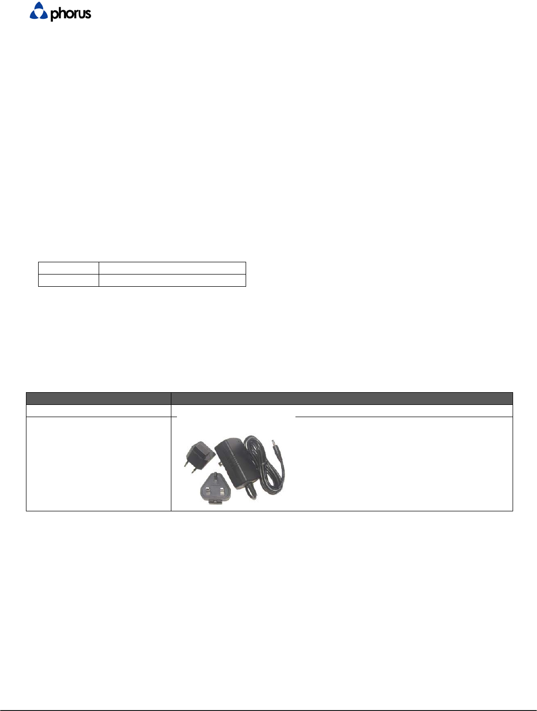
[R128]. The power supply shall be a wall-wart type universal switching power supply in order to
accommodate world wide use.
[R129]. The captured 1.5 meter long 2-conductor power output cable shall terminate in a barrel type
connector with the power input jack on the rear of the Pan unit (see section 6.3.1.1)
[R130]. The power supply shall have the following characteristics:
Input
100-240 V AC 50/60 Hz
Output
12V DC 2A
[R131]. It is highly desired for the AC power cord to be as thin and flexible and also to have a small as
possible connector. This way the user can elegantly route the power cord to their desire. If possible,
the power cord should have 2 conductors and no ground as long as it passes all regulatory
requirements.
[R132]. The EMEA power supply shall have interchangeable plugs for EU and UK.
[R133]. The following images are descriptions for each power supply type. They are grouped by SKU.
The images are for informational use only:
SKU:
Power Supply Type:
Americas
Fixed Pins
EMEA
9.2 DSP
9.2.1 Audio Routing
[R134]. The unit shall support playback of any one audio source at any time. The sources are:
[R135]. Bluetooth Subsystem
[R136]. Wi-Fi Subsystems (For Caprica Module Only)
[R137]. System Sounds
9.2.2 Filters and Limiter / Compressor
[R138]. The signal processing block of the system shall be capable of processing a minimum of 5 biquads
per channel. Provisions shall be made for Phorus to access the DSP to modify the filter coefficients
for acoustic tuning.

Confidential - Do Not Distribute Revision A - Sep. 9 2011 page 18 of 18
[R139]. The amplifier response shall be capable of being flat between 20Hz to 20kHz. In the audio path a
DSP shall be used in order to correct for any linear acoustic distortion.
[R140]. The system shall also have a limiter in order to optimize the max power max bandwidth
parameters.
9.2.3 System Volume
[R141]. The main system volume shall have 30 steps, representing gain of –40 dB to 0 dB.
9.3 Testability
[R142]. PCB shall feature test points that allow for 100% nodal coverage.
[R143]. FMEA shall be conducted and addressed.
10 Environmental and Reliability Requirements
[R144]. This product shall conform to the standard environmental and reliability requirements and
guidelines as identified by the operations/quality assurance team.
11 Certification and Agency Compliance
11.1 Intellectual Property Certifications
[R145]. The system shall adhere to the Bluetooth Qualification Program Requirements, as defined in the
Bluetooth Qualification Program Reference Document and be certified by a testing facility (BQTF) and
an expert (BQE).
11.2 Royalties
TBD
11.3 Certifications
The following royalties will be required:
[R146]. VCCI
[R147]. PSE
[R148]. TUV (Germany)
[R149]. EuP
[R150]. RoHS Compliance
[R151]. Safety and emissions requirements for the following countries are required:
a. Europe (CE)
b. USA (FCC, UL)