LITE ON TECHNOLOGY WN4639R 802.11n, 2.4G 1T1R Wireless LAN USB Module User Manual LiteOn Technology Corp
LITE-ON Technology Corp. 802.11n, 2.4G 1T1R Wireless LAN USB Module LiteOn Technology Corp
User Manual
USER MANUAL
802.11n, 2.4G 1T1R Wireless LAN USB Module
WN4639R(5V)
MediaTek MT7601U
Vers ion 1 .1
Change History
Revision Date Author Change Li st
Ve r s i o n 1 . 0 2015/08/08 Ben J Chen Preliminary
Ve r s i o n 1 . 1 2015/09/05 Ben J Chen Update Antenna SPEC
* This document contains confidential proprietary information and is property of LTC. The contents of
this document should not be disclosed to unauthorized persons without the written consent of LTC
Page 2/15
86(50$18$/
802.11n, 2.4G 1T1R Wireless LAN USB Module
WN4639R(5V)
MediaTek MT7601U
Vers ion 1 .1
Networking B.U.
Lite-on Technology Corporation
4F, No. 90, Chien 1 Rd.,
Chung Ho, Ne w Taipei City 235, Taiwan, R.O.C.
Customer Approval: (Signature)
(Title)
(Company)
(Date)
(Please Sign Back by FAX. For Confirming the Spec Only, not an Official Agreement for OEM/ODM Business)
Page 3/1
CONTENT
PRODUCT FEATURES...........................................................................................................................4
PRODUCT SPECIFICATIONS .............................................................................................................5
MAIN CHIPSET ..............................................................................................................................................5
FUNCTIONA L SPECI FICATI O NS .....................................................................................................................5
RECOMMENDED OPERATION CONDITIONS..............................................................................6
DC CHARACTERISTICS .......................................................................................................................6
PIN ASSIGMENT .....................................................................................................................................7
USB CONNECTOR SPEC ......................................................................................................................7
POWER ON SEQUENCE TIMING ......................................................................................................8
RESET TIMING SPEC............................................................................................................................8
MECHANICAL .........................................................................................................................................9
ANTENNA SPEC ................................................................................................................................... 10
EEPROM INFORMATION ................................................................................................................. 13
ENVIRONMENTAL ............................................................................................................................. 13
OPERATING .................................................................................................................................................13
STORA GE .....................................................................................................................................................13
PACKING DRAWING.......................................................................................................................... 14

Page 4/1
PRODUCT FEATURES
zOperate at ISM frequency Band (2.4GHz)
zIEEE Standards Support, 802.11b, 802.11g and 802.11n
zFully comply with USB 2.0 high speed mode
zEnterprise level security supporting: WPA, WPA2, WPS, WAPI
zOne-stream IEEE 802.11n support for 20MHz and 40MHz bandwidth channels
provides PHY layer rates up to 150Mbps
zSupport Wi-Fi Direct
zSupport Wake-On WLAN
zRoHS compliance
zLow Halogen compliance
Applications:
This module is applied to TV product which limit to fixed application.
Page 5/1
PRODUCT SPECIFICATIONS
MAIN CHIPSET
MAC/ Baseband/ RF: MediaTek MT7601U
FUNCTIONAL SPECIFICATIONS
Wi-Fi Function
Standard IEEE802.11b; IEEE 802.11g; IEEE 802.11n
Bus Interface USB2.0
Data Rate
802.11b:
11, 5.5, 2, 1 Mbps
802.11g:
54, 48, 36, 24, 18, 12, 9, 6 Mbps
802.11n:
MCS 0 to 7 for HT20MHz
MCS 0 to 7 for HT40MHz
Media Access Control CSMA/CA with ACK
Modulation Techniques
802.11b:
CCK, DQPSK, DBPSK
802.11g:
64QAM, 16QAM, QPSK, BPSK
802.11n:
64QAM, 16QAM, QPSK, BPSK
Network Architecture Ad-hoc mode (Peer-to-Peer)
Infrastructure mode
Operation Channel
2.4GHz
11: (Ch. 1-11) –United States
13: (Ch. 1-13) –Europe
14: (Ch. 1-14) –Japan
Frequency Range 802.11bg
2.412 ~ 2.4835 GHz
Transmit Output Power –
1x1
(Tolerance: ±1.5dBm)
802.11b:
15 dBm@1~11Mbps
802.11g:
14 dBm@6~54Mbps
802.11n:
20MHz:
14 dBm@MCS0~7
40MHz:
14 dBm@MCS0~7
Receiver Sensitivity
802.11b:
-84 dBm@11Mbps
802.11g:
-71 dBm@54Mbps
802.11n:
20MHz
-70 dBm@MCS7
40MHz
-67 dBm@MCS7
Page 6/1
Security
WPA, WPA2, WPS, WEP 64b&128bit, IEEE 802.1X,
IEEE 802.11i
Operating Voltag
e
5V ±
5% I/O supply voltage
OS
Supported
Microsoft Windows
Win7/Win8; Linux based
Power Consumption
Mode
Average
Peak
TX
RX
Unassociated
Idle
Standby
Antenna Type
One is Metal Antenna, the other is U.FL connector for
plugging external PIFA antenna
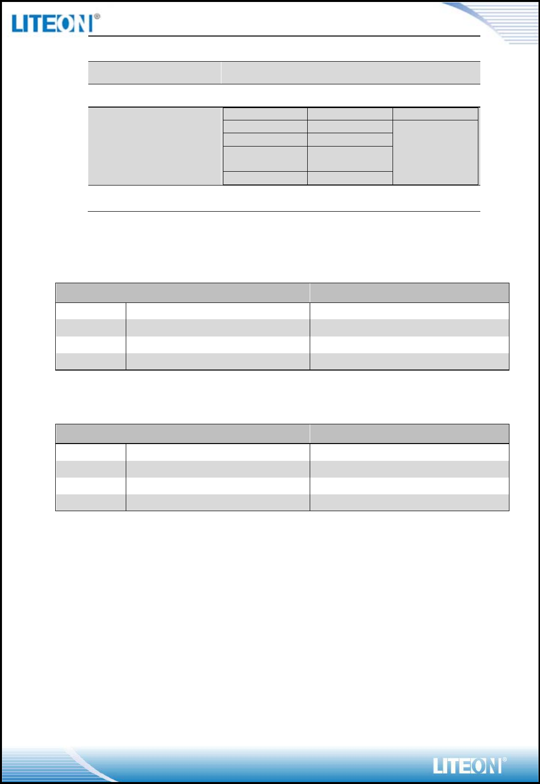
RECOMMENDED OPERATION CONDITIONS
Symbol
Rating
Min
Typ
Max
Units
VCC
5V Supply Voltage
4.75
5
5.25
V
VDD33
3.3V Supply Voltage
2.97
3.3
3.63
V
VDD12
1.2V Supply Voltage
1.14
1.2
1.26
V
VDD15
1.5V Supply Voltage
1.425
1.5
1.575
V
DC CHARACTERISTICS
Symbol
Parameter
Min
Typ
Max
Units
V
IL
Input Low Voltage
-0.28
-
0.6
V
VIH
Input High Voltage
2.0
-
3.63
V
VOL
Output Low Voltage
-0.28
-
0.4
VOH
Output High Voltage
2.4
-
3.63
V
Page 7/1
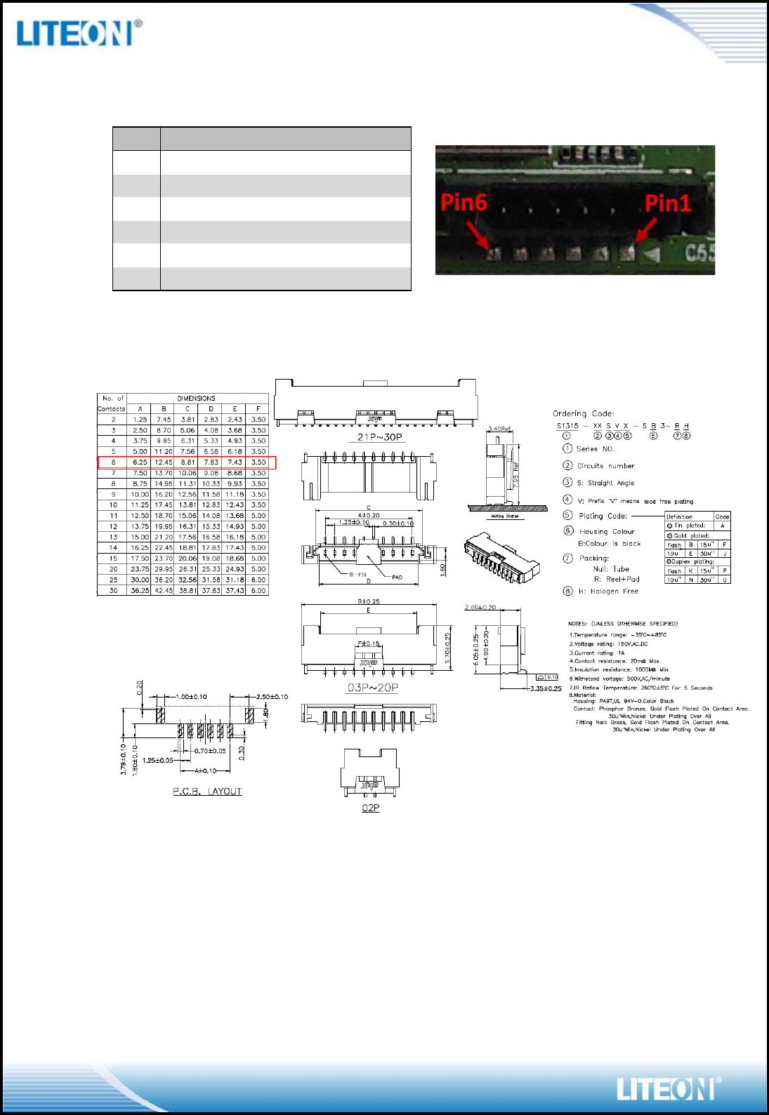
PIN ASSIGMENT
Pin.
Pin Define
Status
1
+5V
YES
2
USB_D-
YES
3
USB_D+
YES
4
GND
YES
5
RESET#(Active Low)
YES
6
WAK E (Active High)
YES
USB CONNECTOR SPEC
Page 8/18
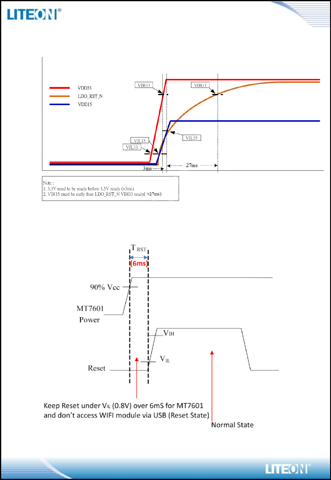
POWER ONSEQUENCE TIMING
RESET TIMING SPEC
Page 9/18
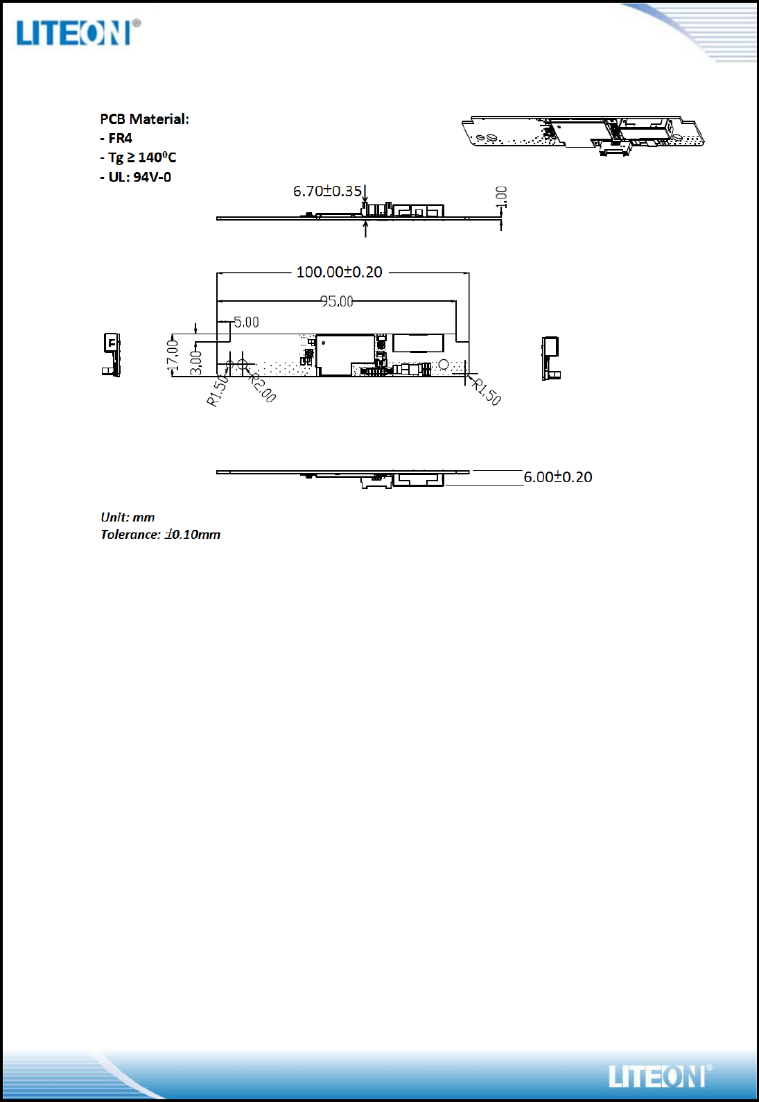
MECHANICAL
BLOCK DIAGRAM
Page 10/18
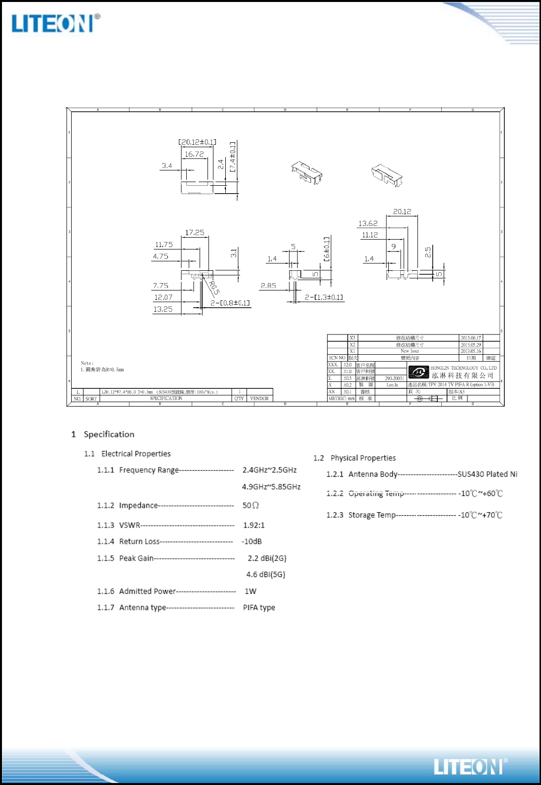
ANTENNA SPEC
Metal Wifi Antenna (Q’ty:1) For RX
Page 11/18
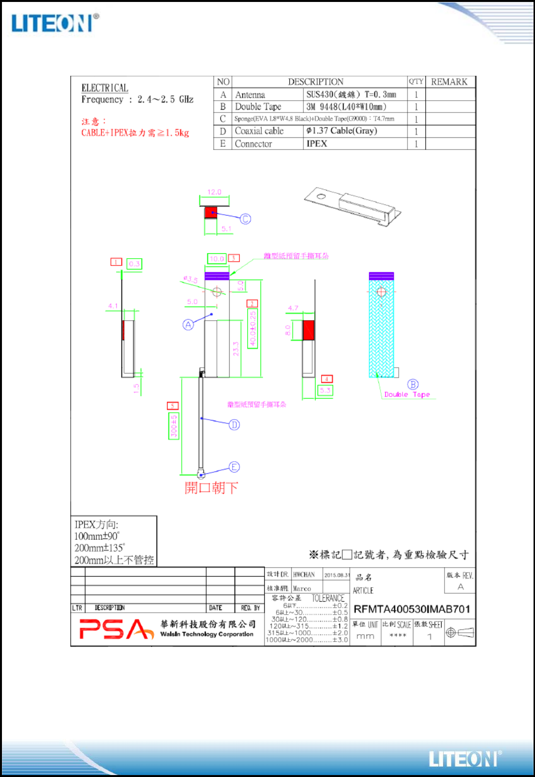
External Wifi Antenna (Q’ty:1) For TX
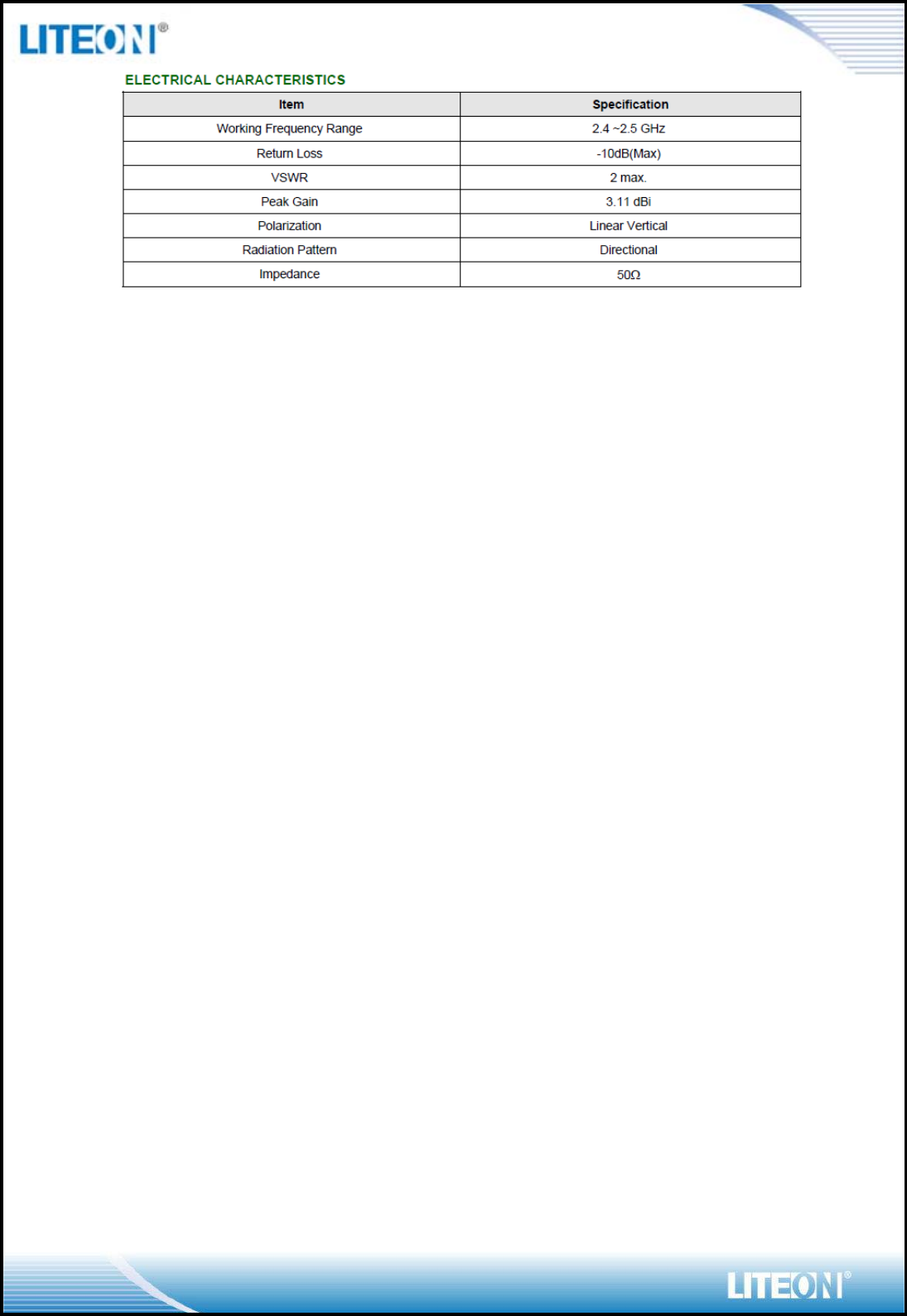
Page 12/18
Page 13/18
EEPROM INFORMATION
Reg Domain
Worldwide
Control by Driver
Offset 0x38 for 5G: 0xFF
Offset 0x39 for 2.4G: 0xFF
Vendor ID 0x148F
Product ID 0x7601
ENVIRONMENTAL
Operating
Operating Temperature: 0 to 60 qC (32 to 140 qF)
Relative Humidity: 5-90% (non-condensing)
Storage
Temperature: -20 to 70 qC (-4 to 158 qF)
Relative Humidity: 5-95% (non-condensing)
Page 14/18
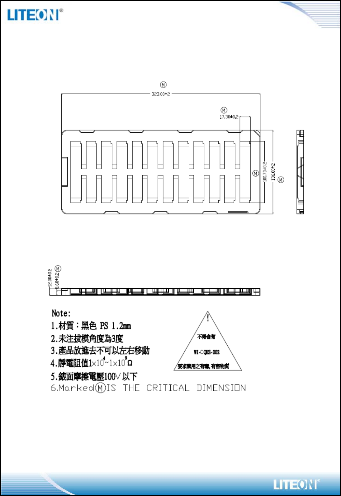
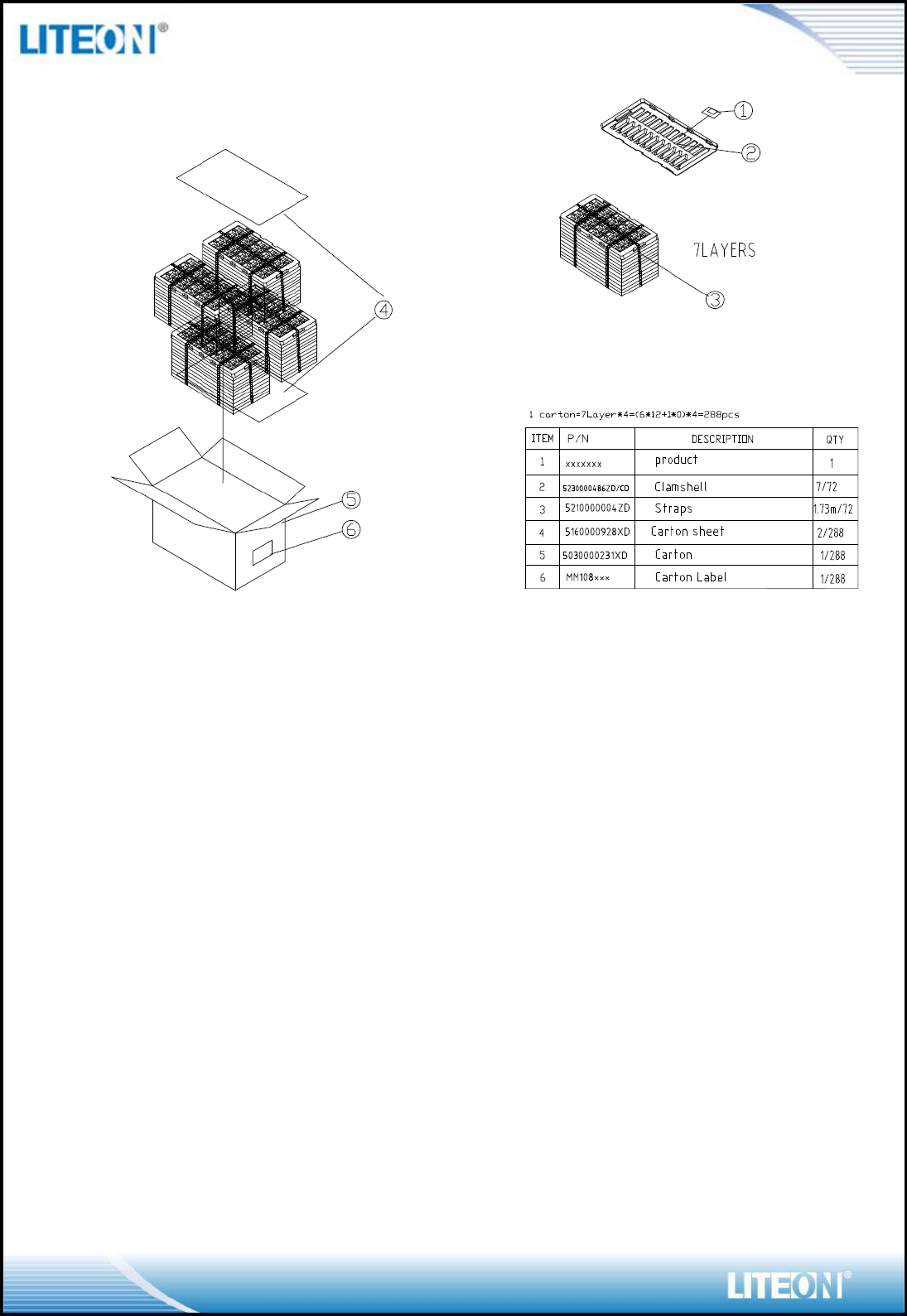
PACKING DRAWING
Tray
Page 15/18

FCC WARING STATEMENT
This equipment has been tested and found to comply with the limits for a Class B digital device,
pursuant to part 15 of the FCC rules. These limits are designed to provide reasonable protection
against harmful interference in a residential installation. This equipment generates, uses and can
radiate radio frequency energy and, if not installed and used in accordance with the instructions,
may cause harmful interference to radio communications. However, there is no guarantee that
interference will not occur in a particular installation. If this equipment does cause harmful
interference to radio or television reception, which can be determined by turning the equipment
off and on, the user is encouraged to try to correct the interference by one or more of the
following measures:
Reorient or relocate the receiving antenna.
Increase the separation between the equipment and receiver.
Connect the equipment into an outlet on a circuit different from that to which the receiver is
connected.
Consult the dealer or an experienced radio/TV technician for help.
You are cautioned that changes or modifications not expressly approved by the party responsible
for compliance could void your authority to operate the equipment.
This device complies with Part 15 of the FCC Rules. Operation is subject to the following two
conditions: (1) this device may not cause harmful interference and (2) this device must accept
any interference received, including interference that may cause undesired operation.
This device and its antenna(s) must not be co-located with any other transmitters except in
accordance with FCC multi-transmitter product procedures.
Refering to the multi-transmitter policy, multiple-transmitter(s) and module(s) can be operated
simultaneously without C2PC.
FCC RF Radiation Exposure Statement:
This equipment complies with FCC RF radiation exposure limits set forth for an uncontrolled
environment. This equipment should be installed and operated with a minimum distance of 20
centimeters between the radiator and your body.
IMPORTANT NOTE:
20 cm minimum distance has to be able to be maintained between the antenna and the users for the
host this module is integrated into. Under such configuration, the FCC radiation exposure limits set
forth for an population/uncontrolled environment can be satisfied.
IMPORTANT NOTE:
This module is intended for OEM integrator. The OEM integrator is responsible for the compliance
to all the rules that apply to the product into which this certified RF module is integrated.
Additional testing and certification may be necessary when multiple modules are used.
USERS MANUAL OF THE END PRODUCT:
In the users manual of the end product, the end user has to be informed to keep at least 20 cm
separation with the antenna while this end product is installed and operated. The end user has to
be infored that the FCC readio-frequency exposure guidelines for an uncontrolled environment
can be satisfied. The end user has to also be informed that any changes or modifications not
expressly approved by the manufacturer could void the user's authority to operated this equipment.
If the size of the end product is smaller than 8x10cm, then additional FCC Part15.19 statement
is required to be availabe in the users manual: (1) this device may not cause harmful interference
and (2) this device must accept any interference received, including inteference that may cause
undesired operation.
OEM/Integrators Installation Manual
The OEM integrator has to be aware not to provide information to the end user regarding how
to install or remove this RF module in the user manual of the end product. The user manual of the
end product which is provided by OEM integrators for end users must include the following
information in a prominent location.
1. To comply with FCC RF exposure compliance requirements, the antenna used for this
transmitter must be installed to provide a separation distance of at least 20 cm from all persons
and must not be co- located or operating in conjunction with any other antenna or transmitter,
except in accordance with FCC multi
transmitter product transmitter product procedures.
It is the responsibility of the professional installer to ensure that the system.
2. Only those antennas with same type and lesser gain filed under this FCC ID number can be
used with this device.
3. The regulatory label on the final system must include the statement: “Contains FCC ID:
PPQ-WN4639R“.

OEM Integrator Checklist
The party below will implement the LITE-ON Module in host systems in accordance with the
instructions specified in this document and the documents referenced herein.
1. The OEM integrator will ensure the Module is integrated in a host systems using only the
approved antenna model(s) described in this document.
2. The OEM integrator will ensure the antenna placement inside the host system will maintain the
required spacing to end user for RF Exposure compliance, as specified in this document.
3. If other radios are integrated inside the host with the LITE-ON Module, the OEM integrator will
contact its test lab, TCB or LITE-ON to determine if additional FCC compliance evaluation is
required to meet FCC collocation rules.
4. The OEM integrator will ensure end user documentation will contain the specified regulatory
wording and ensure the host system and the Module itself are labeled as specified in this document.
5. The OEM integrator will ensure the Module is programmed in the factory with compliant transmit
power not exceeding the levels specified in this document.
LITE-ON requests that the OEM integrator acknowledge its receipt of this document and the above
instructions. You may contact LITE-ON with any questions concerning this document or the
responsibilities of the OEM integrator.