LM Technologies LM072 BLUETOOTH MODULE User Manual LM072 Datasheet FCC
LM Technologies Ltd. BLUETOOTH MODULE LM072 Datasheet FCC
USERS MANUAL
LM072
Page 1 of 7
+44(0) 207 428 2647 www.lm-technologies.com | sales@lm-technologies.com
3 Applications
2 Features
LM072 Class 1 Bluetooth Serial Data Module
• Bluetooth v2.0 + EDR and v2.1 + EDR compliant firmware available
• Class 1 radio - Output power +13 dBm
• 100 m range in open space
• Secure Simple Pairing supported (in Bluetooth 2.1 + EDR firmware)
• 3V - 3.6V operaon
• Full Bluetooth EDR data rate of upto 3 Mbps supported
• Interface : UART (upto 921600 bps), PIO
• Mulpoint firmware support
• SPP firmware supported by default. HID firmware available upon
request
• CSR Bluecore 04 (BC04) chipset
• AT Command set provided for module configuraon
• 802.11 Coexistence supported
• Lead free - RoHS compliant
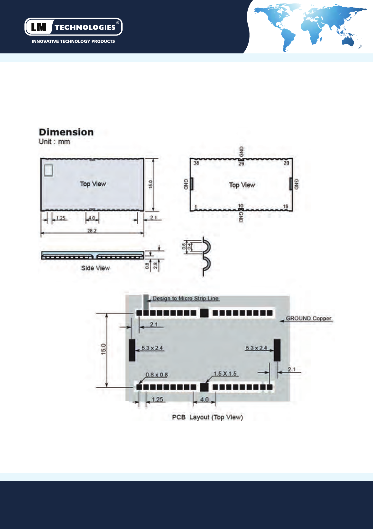
• Small Size : 28.2 mm x 15.0 mm x 2.8 mm
Product: LM072
Part No: 072-0125 for BT2.0 F/W
Part No: 072-0110 for BT2.1 F/W
Datasheet Rev1.2/11-07-12
• Serial Communicaons
• Medical Devices
• Domesc and Industrial Applicaons
• Embedded Devices
• Remote Monitoring and Control
• Payment Terminals
• GPS, POS, Barcode Readers
1 General Description
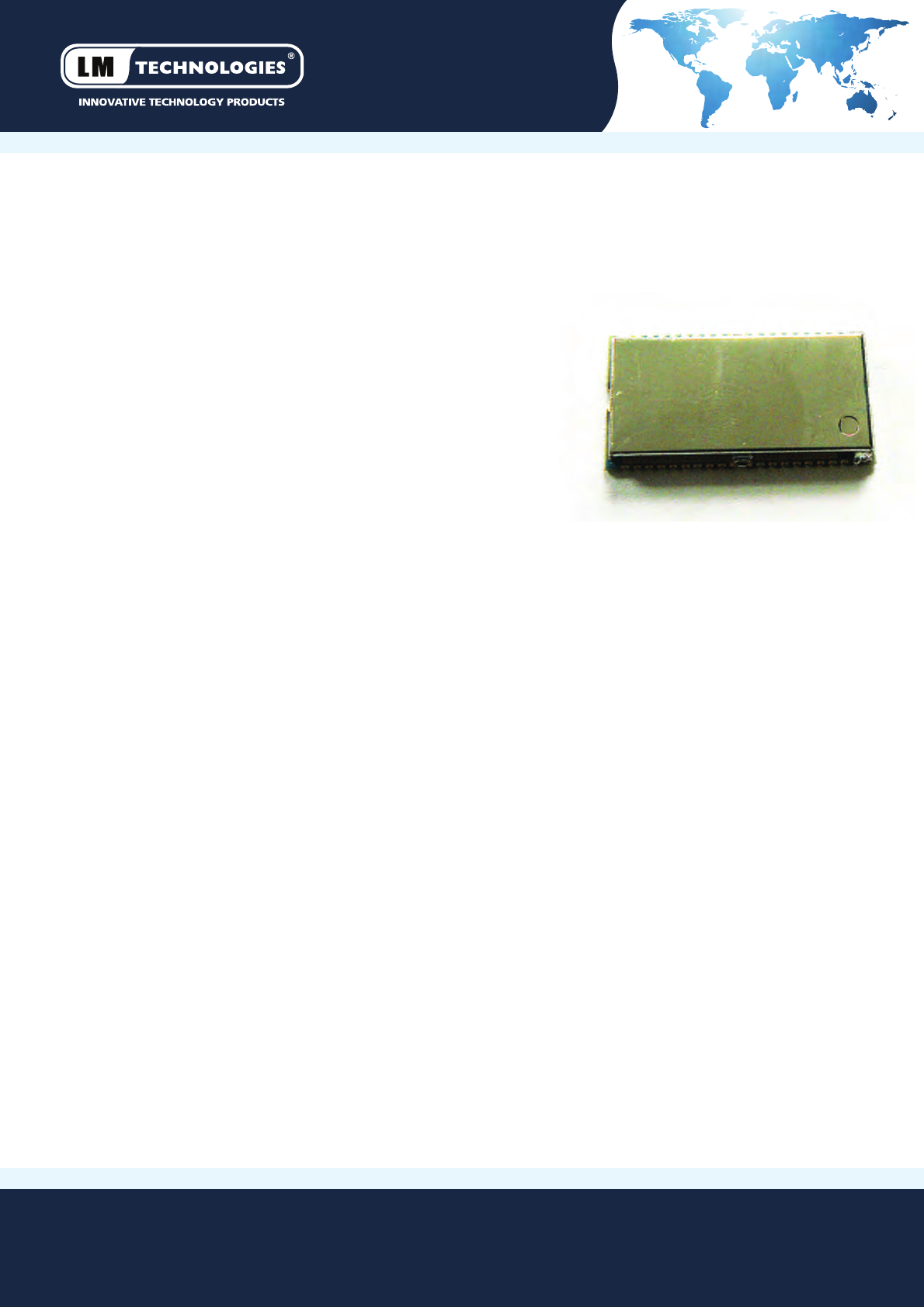
LM072 is LM Technologies Ltd Class 1 Bluetooth Data module with
external antenna. This module is a CSR Bluecore 4 (BC04) chip based surface
mount module available with Bluetooth Serial Port Profile (SPP) firmware.
This module is ideal for adding long range wireless connecvity to embedded
products.
The module acts as a standalone unit (i.e. it does not need a host
to drive it) and can interface with embedded microcontrollers via UART.
It operates over a voltage range of 3.0 V to 3.6 V and gives excellent
performance over a distance of 70-100 m with external antenna.
This is a tried and tested module also used in other LM best selling products
like LM048 and LM058 serial adapter as well as LM400 and LM410 Data Modules.
This module is available with Bluetooth 2.0+EDR as well as Bluetooth
2.1+EDR compliant SPP firmware.
LM072
Page 2 of 7 +44(0) 207 428 2647 www.lm-technologies.com | sales@lm-technologies.com
4 Packaging Options
LM072 with BT2.0 + EDR firmware
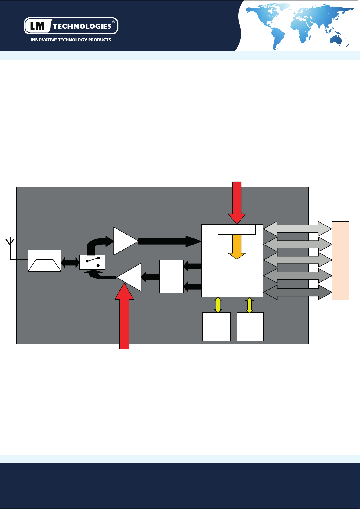
5 Block Diagram
Tape and Reel
Part No 072-0127
Tray Packaging
Part No 072-0126
Product: LM072
Part No: 072-0125 for BT2.0 F/W
Part No: 072-0110 for BT2.1 F/W
Datasheet Rev1.2/11-07-12
LM072 with BT2.0 + EDR firmware
Part No 072-0112
LM072 with BT2.1 + EDR firmware
Part No 072-0111
LM072 with BT2.1 + EDR firmware
Note: USB and PCM interface are not handled by LM firmware at present
Rx_IN
Tx_A
BLUECORE4-EXT
Tx_B
26MHz
XTAL
8 MB
FLASH
REGULATOR
SPI
UART
USB
PCM
PIO
BALUN
I
N
T
E
R
F
A
C
E
LNA
PVCC
POWER
AMP
SWITCH
BPF
VDD
VDD1.8V

LM072
Page 3 of 7
6 Electrical Characteristics
7 Factory Settings
The factory sengs of the COM Port are as follows:
Baud Rate: 19200 bps
Data Bits: 8
Parity: None
Stop Bits: 1
Flow Control: Hardware (BT2.0) or None (BT2.1)
+44(0) 207 428 2647 www.lm-technologies.com | sales@lm-technologies.com
Product: LM072
Part No: 072-0125 for BT2.0 F/W
Part No: 072-0110 for BT2.1 F/W
Datasheet Rev1.2/11-07-12
Absolute Maximum Rangs
Parameter
Min
Max
Unit
Storage Temperature -40 +85 °C
Supply Voltage (VDD) +2.7 +3.6 V
Supply Voltage (PVCC)
+3.0
+3.6
V
All other pins
VSS - 0.4
VDD+0.4
V
Recommended Operang Condions
Parameter Min Max Unit
Storage Temperature
-20
+75
°C
Supply Voltage (VDD) +3.0 +3.3 V
Supply Voltage (PVCC)
+3.0
+3.3
V
General Electrical Specificaon
Parameter Descripon Min Typical Max Unit
Carrier Frequency
2.402
2.480
GHz
RF Output power Measured with 50Ω ant 10 11.5 13 dBm
Rx Sensivity
-
-88
-86
dBm
Load Impedance
No abnormal oscillaon
5:1
Input Low Voltage
RESET, UART, GPIO, PCM
-0.3
-
0.8
DCV
Input High Voltage RESET, UART, GPIO, PCM 0.7VDD -VDD+0.3 DCV
Output Low Voltage UART, GPIO, PCM - - 0.4 DCV
Output High Voltage
UART, GPIO, PCM
VDD-0.4
-
-
DCV
Average Current
Consumpon
Receive DM1 114 mA
LM072
Page 4 of 7
8 Pin Assignments
+44(0) 207 428 2647 www.lm-technologies.com | sales@lm-technologies.com
Product: LM072
Part No: 072-0125 for BT2.0 F/W
Part No: 072-0110 for BT2.1 F/W
Datasheet Rev1.2/11-07-12
Pin Number
Name
Type
Descripon
1 GND Ground Common Ground
2 PVCC Power Power Amp. Power supply (3.3V)
3
AIO 0
I/O
Programmable Input Output
4
AIO 1
I/O
Programmable Input Output
5 PIO 0 I/O Programmable Input Output
6 PIO 1 I/O Programmable Input Output
7
PIO 2
I/O
Programmable Input Output
8 PIO 3 I/O Programmable Input Output
9
PIO 4
I/O
Programmable Input Output
10 GND Ground Common Ground
11
PIO 5
I/O
Programmable Input Output
12 PIO 6 I/O Programmable Input Output
13
PIO 7
I/O
Programmable Input Output
14 PIO 8 I/O Programmable Input Output
15
PIO 9
I/O
Programmable Input Output
16 RESET CMOS Input Reset Input of Module, Acve Low
17 VCC Power Module input Supply, 3.3V DC
18 GND Ground Common Ground
19
GND
Ground
Common Ground
20 USB_DP I/O USB Data Plus
21 USB_DNI/O USB Data Minus
22 PCM_SYNC I/O Synchronous Data Sync
23
PCM_IN
CMOS Input
Synchronous Data Input
24 PCM_OUT CMOS Output Synchronous Data Output
25 PCM_CLKI/O Synchronous Data Clock
26
UART_RX
CMOS Input
UART Data Input
27 UART_TXCMOS Output UART Data Output
28 UART_RTS CMOS Output UART Request to Send (Acve Low)
29 GND Ground Common Ground
30
UART_CTS
CMOS Input
UART Clear to Send (Acve Low)
31 SPI_MOSI CMOS Input Serial Peripheral Interface Data Input
32 SPI_CSB CMOS Input Chip Select for Serial Peripheral Interface (Acve Low)
33 SPI_CLKCMOS Input Serial Peripheral Interface Clock
34
SPI_MISO
CMOS Output
Serial Peripheral Interface Data Output
35 PIO 11 I/O Programmable Input Output
36
PIO 10
I/O
Programmable Input Output
37
RF_IO
Analogue
Antenna Interface
38 GND Ground Common Ground
LM072
Page 5 of 7
+44(0) 207 428 2647 www.lm-technologies.com | sales@lm-technologies.com
Product: LM072
Part No: 072-0125 for BT2.0 F/W
Part No: 072-0110 for BT2.1 F/W
Datasheet Rev1.2/11-07-12
9 Dimensions

LM072
Page 6 of 7
+44(0) 207 428 2647 www.lm-technologies.com | sales@lm-technologies.com
Product: LM072
Part No: 072-0125 for BT2.0 F/W
Part No: 072-0110 for BT2.1 F/W
Datasheet Rev1.2/11-07-12
10 FCC Warning
This device complies with Part 15 of the FCC Rules. Operaon is subject to the following two condions:
(1) this device may not cause harmful interference, and
(2) this device must accept any interference received, including interference that may cause undesired operaon.
NOTE 1: This equipment has been tested and found to comply with the limits for a Class B digital device, pursuant to part 15
of the FCC Rules. These limits are designed to provide reasonable protecon against harmful interference in a residenal
installaon. This equipment generates, uses and can radiate radio frequency energy and, if not installed and used in accordance
with the instrucons, may cause harmful interference to radio communicaons. However, there is no guarantee that interference
will not occur in a parcular installaon. If this equipment does cause harmful interference to radio or television recepon,
which can be determined by turning the equipment off and on, the user is encouraged to try to correct the interference by
one or more of the following measures:
- Reorient or relocate the receiving antenna.
- Increase the separaon between the equipment and receiver.
- Connect the equipment into an outlet on a circuit different from that to which the receiver is connected.
- Consult the dealer or an experienced radio/TV technician for help.
NOTE 2: Any changes or modificaons to this unit not expressly approved by the party responsible for compliance could
void the user's authority to operate the equipment.
11 FCC Radiation Exposure Statement
This equipment complies with FCC radiaon exposure limits set forth for an uncontrolled environment. End users must follow
the specific operang instrucons for sasfying RF exposure compliance.
Note 1: This module cerfied that complies with RF exposure requirment under portable or mobile or fixed condion,
this module is to be installed only in portable or mobile or fixed applicaons.
A portable device is defined as a transming device designed to be used so that the radiang structure(s) of the device
is/are within 20 cenmeters of the body of the user
A mobile device is defined as a transming device designed to be used in other than fixed locaons and to generally
be used in such a way that a separaon distance of at least 20 cenmeters is normally maintained between the transmier's
radiang structure(s) and the body of the user or nearby persons. Transming devices designed to be used by consumers or
workers that can be easily re-located, such as wireless devices associated with a personal computer, are considered to be mobile
devices if they meet the 20 cenmeter separaon requirement.
A fixed device is defined as a device is physically secured at one locaon and is not able to be easily moved to another locaon.
Note 2: Any modificaons made to the module will void the Grant of Cerficaon, this module is limited to OEM installaon
only and must not be sold to end-users, end-user has no manual instrucons to remove or install the device, only soware or
operang procedure shall be placed in the end-user operang manual of final products.
Note 3: The device must not transmit simultaneously with any other antenna or transmier.
LM072
Page 7 of 7
+44(0) 207 428 2647 www.lm-technologies.com | sales@lm-technologies.com
Product: LM072
Part No: 072-0125 for BT2.0 F/W
Part No: 072-0110 for BT2.1 F/W
Datasheet Rev1.2/11-07-12
Note 4: To ensure compliance with all non-transmier funcons the host manufacturer is responsible for ensuring compliance
with the module(s) installed and fully operaonal. For example, if a host was previously authorized as an unintenonal
radiator under the Declaraon of Conformity procedure without a transmier cerfied module and a module is added, the
host manufacturer is responsible for ensuring that the aer the module is installed and operaonal the host connues to be
compliant with the Part 15B unintenonal radiator requirements. Since this may depend on the details of how the module
is integrated with the host, LM Technologies Ltd shall provide guidance to the host manufacturer for compliance with the
Part 15B requirements.
Note 5: FCC ID label on the final system must be labeled with “Contains FCC ID: VVXLM072” or “Contains transmier module
FCC ID: VVXLM072”.
The transmier module must be installed and used in strict accordance with the manufacturer's instrucons as described in
the user documentaon that comes with the host product. LM Technologies Ltd is responsible for the compliance of the module
in all final hosts.
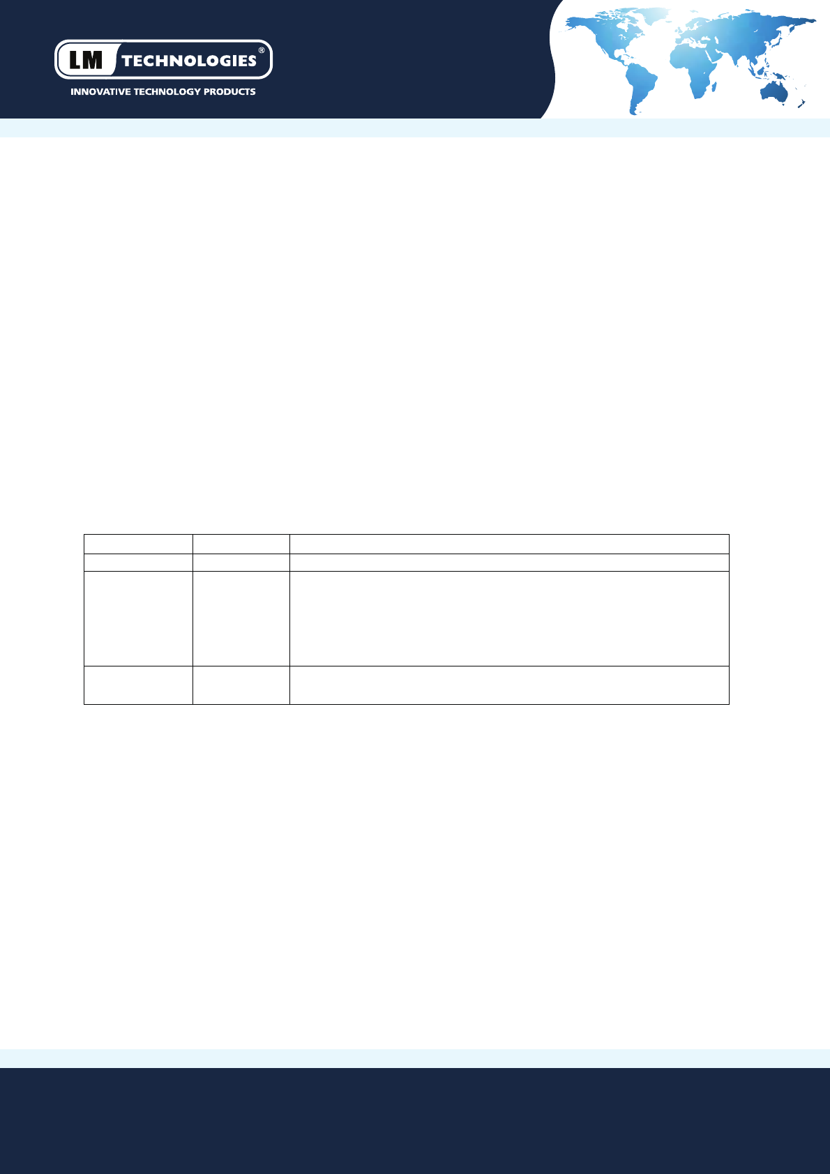
12 Revision History
Revision Date Comments
Rev1.0
17/12/2010
First Version
Rev1.1
03/07/2012 1. Reformaed the datasheet
2. Added packaging opons
3. Added part number informaon
4. Added FCC Regulaon Statement
5. Added Revision History
Rev1.2 11/07/2012 1. Change to FCC Warning Statement
2. Added FCC Radiaon Exposure Statement